UNIT I Network architecture - Fmcetfmcet.in/CSE/CS2302_uw.pdf · The transmission are occurred only...
122
CS2302 COMPUTER NETWORKS 1 CS2302 COMPUTER NETWORKS UNIT I Network architecture – layers – Physical links – Channel access on links – Hybrid multiple access techniques - Issues in the data link layer - Framing – Error correction and detection – Link-level Flow Control INTRODUCTION TO DATA COMMUNICATIONS: It is the exchange of data between two devices through some transmission medium. Types: 1. Local 2. Remote 1. Local: If the devices are restricted in a geographical area. 2. Remote: If the devices are farther away without any geographical restriction. Fundamental Characteristics: 1. Delivery 2. Accuracy 3. Timeliness Components: Data communication systems are made up of five components. 1. Message 2. sender 3. Receiver 4. Medium 5. Protocol 1. Message: This is the information to be communicated. It can consist of text, numbers, pictures, sound or video or any combination of these.
Transcript of UNIT I Network architecture - Fmcetfmcet.in/CSE/CS2302_uw.pdf · The transmission are occurred only...
CS2302 COMPUTER NETWORKS
1
CS2302 COMPUTER NETWORKS
UNIT I
Network architecture – layers – Physical links – Channel access on links – Hybrid
multiple access techniques - Issues in the data link layer - Framing – Error correction and
detection – Link-level Flow Control
INTRODUCTION TO DATA COMMUNICATIONS:
It is the exchange of data between two devices through some transmission
medium.
Types:
1. Local
2. Remote
1. Local:
If the devices are restricted in a geographical area.
2. Remote:
If the devices are farther away without any geographical restriction.
Fundamental Characteristics:
1. Delivery
2. Accuracy
3. Timeliness
Components:
Data communication systems are made up of five components.
1. Message
2. sender
3. Receiver
4. Medium
5. Protocol
1. Message:
This is the information to be communicated. It can consist of text, numbers,
pictures, sound or video or any combination of these.
CS2302 COMPUTER NETWORKS
2
2. Sender:
It is the device that sends the data message. It may be a computer, workstation,
telephone handset, video camera…
3. Receiver:
It is the device that receives the message. It may be a computer, workstation,
telephone handset, television…
4. Medium:
It is the physical path which a message travels from sender to receiver. It may
consist of twisted pair wire, coaxial cable, fiber optic cable, laser or radio waves.
5. Protocol:
It is a set of rules that governs data communication. It is a agreement between the
communication devices.
NETWORKS:
A network is a set of devices connected by a media link. Devices often referred to
as nodes can be a computer, printer, or any other devices capable of sending/ receiving
data.
Distributed processing:
Here tasks are divided among multiple computers. Each separate computer
handles a subset.
Advantages:
1. Security/ Encapsulation
2. Distributed database
3. Faster problem solving
4. Security through redundancy
5. collaborative processing
Network Criteria:
A network must meet a number of criteria to be considered as effective and
efficient.
The criteria are,

CS2302 COMPUTER NETWORKS
3
1. Performance
2. Reliability
3. Security
1. Performance:
The performance can be measured by two times are,
I. Transit time
II. Response time
I. Transit time:
It is the amount of time required for a message to travel from one device to
another device.
II. Response time:
It is the elapsed time between an inquiry and a response.
The performance can be measured by number factors are,
i. Number of user
ii. Type of transition medium
iii. Hardware
iv. Software
i. Number of user:
Large number of concurrent users produces slow response time and heavy traffic
loads.
ii. Type of transition medium:
The medium defines the speed of data travel.
iii. Hardware:
The type of hardware can affect the speed and capacity of transmission.
iv. Software:
The software can affect speed and reliability of a network link.
2. Reliability:
The reliability is measured by frequency to failure, the time it takes a link to
recover from a failure and the network‟s robustness in a catastrophe.
i. Frequency of Failure:
A network that fails often.
CS2302 COMPUTER NETWORKS
4
ii. Recovery time:
How much time it takes to recover service after a failure has occurred?
iii. Catastrophe:
Failures due to such reasons are fire, earthquake, theft…
3. Security:
It refers to protecting data from unauthorized access and viruses.
i. Unauthorized Access:
Sensitive data must be protected from unauthorized access. Protection can be
done by user identification and passwords at the lowest level. At the highest level,
encryption techniques may use.
ii. Viruses:
A virus is an illicitly introduced code that damages the system.
CATEGORIES OF NETWORKS:
There are three primary categories are,
1. Local area network.
2. Metropolitan area network.
3. Wide area network.
1. Local Area Network:
They are usually privately owned and link the devices in a single office, building
and campus. Currently LAN size is limited to a few kilometers. It may be from two PC‟s
to throughout a company.
The most common LAN topologies are bus, ring and star. They have data rates
from 4 to 16 Mbps. Today the speed is on increasing and can reach 100 mbps.
2. Metropolitan Area Network:
They are designed to extend over an entire city. It may be a single network or
connecting a number of LANs into a large network. So the resources are shared between
LANs. Example of MAN is, telephone companies provide a popular MAN service called
switched multi megabit data service (SMDS).
CS2302 COMPUTER NETWORKS
5
3. Wide Area Network:
It provides a long distance transmission of data, voice, image and video
information over a large geographical are like country, continent or even the whole
world.
TYPE OF CONNECTION:
There are two types are,
1. Point to point
2. Multi point
1. Mesh
2. Star
3. Tree
4. Bus
5. Ring

CS2302 COMPUTER NETWORKS
6
1. Mesh Topology:
Here every device has a dedicated point to point link to every other device. A
fully connected mesh can have n(n-1)/2 physical channels to link n devices. It must have
n-1 IO ports.
Figure: Mesh Topology
Advantages:
1. They use dedicated links so each link can only carry its own data load. So traffic
problem can be avoided.
2. It is robust. If any one link get damaged it cannot affect others
3. It gives privacy and security
4. Fault identification and fault isolation are easy.
Disadvantages:
1. The amount of cabling and the number IO ports required are very large. Since
every device is connected to each other devices through dedicated links.
2. The sheer bulk of wiring is larger then the available space
3. Hardware required to connect each device is highly expensive.

CS2302 COMPUTER NETWORKS
7
Example:
A mesh network has 8 devices. Calculate total number of cable links and IO ports
needed.
Solution:
Number of devices = 8
Number of links = n (n-1)/2
= 8(8-1)/2
= 28
Number of port/device = n-1
= 8-1 = 7
2. STAR TOPOLOGY:
Here each device has a dedicated link to the central „hub‟. There is no direct
traffic between devices. The transmission are occurred only through the central controller
namely hub.
Figure: Star Topology
Advantages:
1. Less expensive then mesh since each device is connected only to the hub.
2. Installation and configuration are easy.
3. Less cabling is need then mesh.
4. Robustness.
5. Easy to fault identification & isolation.
CS2302 COMPUTER NETWORKS
8
Disadvantages:
1. Even it requires less cabling then mesh when compared with other topologies it
still large.
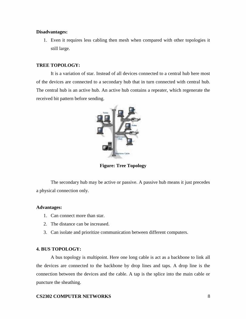
TREE TOPOLOGY:
It is a variation of star. Instead of all devices connected to a central hub here most
of the devices are connected to a secondary hub that in turn connected with central hub.
The central hub is an active hub. An active hub contains a repeater, which regenerate the
received bit pattern before sending.
Figure: Tree Topology
The secondary hub may be active or passive. A passive hub means it just precedes
a physical connection only.
Advantages:
1. Can connect more than star.
2. The distance can be increased.
3. Can isolate and prioritize communication between different computers.
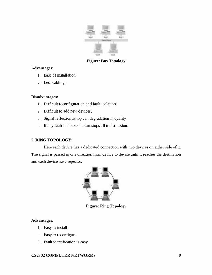
4. BUS TOPOLOGY:
A bus topology is multipoint. Here one long cable is act as a backbone to link all
the devices are connected to the backbone by drop lines and taps. A drop line is the
connection between the devices and the cable. A tap is the splice into the main cable or
puncture the sheathing.
CS2302 COMPUTER NETWORKS
9
Figure: Bus Topology
Advantages:
1. Ease of installation.
2. Less cabling.
Disadvantages:
1. Difficult reconfiguration and fault isolation.
2. Difficult to add new devices.
3. Signal reflection at top can degradation in quality
4. If any fault in backbone can stops all transmission.
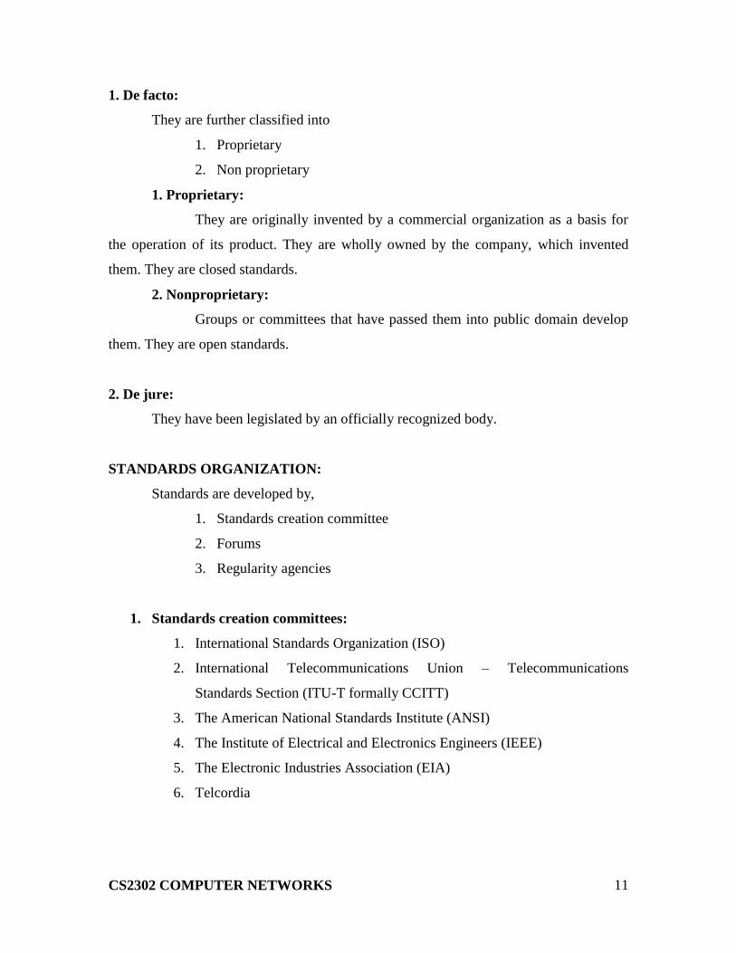
5. RING TOPOLOGY:
Here each device has a dedicated connection with two devices on either side of it.
The signal is passed in one direction from device to device until it reaches the destination
and each device have repeater.
Figure: Ring Topology
Advantages:
1. Easy to install.
2. Easy to reconfigure.
3. Fault identification is easy.

CS2302 COMPUTER NETWORKS
10
Disadvantages:
1. Unidirectional traffic.
2. Break in a single ring can break entire network.
PROTROCOLS AND STANDARDS:
Protocols:
In computer networks, communication occurs between entries in different
systems. An entity is anything capable of sending or receiving information. But two
entities cannot communicate each other as sending or receiving. For communication
occurs the entities must agree on a protocol.
A protocol is a set of rules that govern data communication. A protocol defines
what is communicated how it is communicated, and when it is communicated. The key
elements of a protocol are syntax, semantics and timing.
Syntax:
Syntax refers to the structure or format of the data, means to the order how it is
presented.
Semantics:
Semantics refers to the meaning of each section of bits. How is a particular
pattern to be interpreted, and when action is to be taken based on the interpretation.
Timing:
Timing refers to two characteristics. They are,
1. When data should be sent
2. When data to be received.
Standards:
A standard provides a model for development of a product, which is going to
develop. Standards are essential to create and maintain a product.
Data communication products are fall into two categories. They are,
1. De facto
2. De jure
CS2302 COMPUTER NETWORKS
11
1. De facto:
They are further classified into
1. Proprietary
2. Non proprietary
1. Proprietary:
They are originally invented by a commercial organization as a basis for
the operation of its product. They are wholly owned by the company, which invented
them. They are closed standards.
2. Nonproprietary:
Groups or committees that have passed them into public domain develop
them. They are open standards.
2. De jure:
They have been legislated by an officially recognized body.
STANDARDS ORGANIZATION:
Standards are developed by,
1. Standards creation committee
2. Forums
3. Regularity agencies
1. Standards creation committees:
1. International Standards Organization (ISO)
2. International Telecommunications Union – Telecommunications
Standards Section (ITU-T formally CCITT)
3. The American National Standards Institute (ANSI)
4. The Institute of Electrical and Electronics Engineers (IEEE)
5. The Electronic Industries Association (EIA)
6. Telcordia

CS2302 COMPUTER NETWORKS
12
2. Forums:
1. Frame Relay Forum
2. ATM Forum & ATM consortium
3. Internet Society (ISOC) & Internet Engineering Task Force (IETF)
3. Regularity Agencies:
CS2302 COMPUTER NETWORKS
13
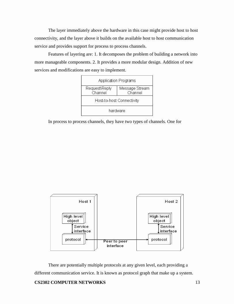
The layer immediately above the hardware in this case might provide host to host
connectivity, and the layer above it builds on the available host to host communication
service and provides support for process to process channels.
Features of layering are: 1. It decomposes the problem of building a network into
more manageable components. 2. It provides a more modular design. Addition of new
services and modifications are easy to implement.
In process to process channels, they have two types of channels. One for
There are potentially multiple protocols at any given level, each providing a
different communication service. It is known as protocol graph that make up a system.

CS2302 COMPUTER NETWORKS
14
ISO / OSI MODEL:
ISO refers International Standards Organization was established in 1947, it is a
multinational body dedicated to worldwide agreement on international standards.
OSI refers to Open System Interconnection that covers all aspects of network
communication. It is a standard of ISO.
Here open system is a model that allows any two different systems to
communicate regardless of their underlying architecture. Mainly, it is not a protocol it is
just a model.
OSI MODEL
The open system interconnection model is a layered framework. It has seven
separate but interrelated layers. Each layer having unique responsibilities.
ARCHITECTURE
The architecture of OSI model is a layered architecture. The seven layers are,
1. Physical layer
2. Datalink layer
3. Network layer
4. Transport layer
CS2302 COMPUTER NETWORKS
15
5. Session layer
6. Presentation layer
7. Application layer
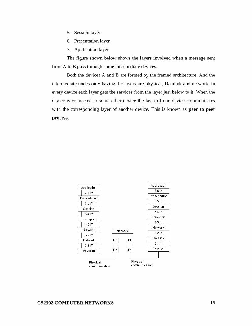
The figure shown below shows the layers involved when a message sent
from A to B pass through some intermediate devices.
Both the devices A and B are formed by the framed architecture. And the
intermediate nodes only having the layers are physical, Datalink and network. In
every device each layer gets the services from the layer just below to it. When the
device is connected to some other device the layer of one device communicates
with the corresponding layer of another device. This is known as peer to peer
process.

CS2302 COMPUTER NETWORKS
16
ORGANIZATION OF LAYERS
The seven layers are arranged by three sub groups.
1. Network Support Layers
2. User Support Layers
3. Intermediate Layer
Network Support Layers:
Physical, Datalink and Network layers come under the group. They deal
with the physical aspects of the data such as electrical specifications, physical
connections, physical addressing, and transport timing and reliability.
User Support Layers:
Session, Presentation and Application layers comes under the
group. They deal with the interoperability between the software systems.
Intermediate Layer
The transport layer is the intermediate layer between the network support
and the user support layers.
FUNCTIONS OF THE LAYERS
PHYSICAL LAYER
The physical layer coordinates the functions required to transmit a bit
stream over a physical medium. It deals with the mechanical and electrical
specifications of the interface and the transmission medium.

CS2302 COMPUTER NETWORKS
17
The functions are,
1. Physical Characteristics Of Interfaces and Media:
It defines the electrical and mechanical characteristics of the
interface and the media.
It defines the types of transmission medium
2. Representation of Bits
To transmit the stream of bits they must be encoded into signal.
It defines the type of encoding weather electrical or optical.
3. Data Rate
It defines the transmission rate i.e. the number of bits sent per
second.
4. Synchronization of Bits
The sender and receiver must be synchronized at bit level.
1. point to point
2. multipoint
6. Physical Topology
It defines how devices are connected to make a network.
Five topologies are,
1. mesh
2. star
3. tree
4. bus
5. ring
7. Transmission Mode
It defines the direction of transmission between devices.
Three types of transmission are,
1. simplex
2. half duplex

CS2302 COMPUTER NETWORKS
18
3. full duplex
DATALINK LAYER
Datalink layer responsible for node-to-node delivery.
The responsibilities of Datalink layer are,
1. Framing
It divides the stream of bits received from network layer into manageable
data units called frames.
2. Physical Addressing
It adds a header that defines the physical address of the sender
and the receiver.
If the sender and the receiver are in different networks, then the
receiver address is the address of the device which connects the
two networks.
3. Flow Control
It imposes a flow control mechanism used to ensure the
data rate at the sender and the receiver should be same.
4. Error Control
To improve the reliability the Datalink layer adds a trailer
which contains the error control mechanism like CRC,
Checksum etc.
CS2302 COMPUTER NETWORKS
19
5. Access Control
When two or more devices connected at the same link, then
the Datalink layer used to determine which device has
control over the link at any given time.
NETWORK LAYER
When the sender is in one network and the receiver is in some
other network then the network layer has the responsibility for the source to
destination delivery.
The responsibilities are,
1. Logical Addressing
If a packet passes the network boundary that is when the sender
and receiver are places in different network then the network layer
adds a header that defines the logical address of the devices.
2. Routing
When more than one networks connected and to form an
internetwork, the connecting devices route the packet to its final
destination.
Network layer provides this mechanism.
CS2302 COMPUTER NETWORKS
20
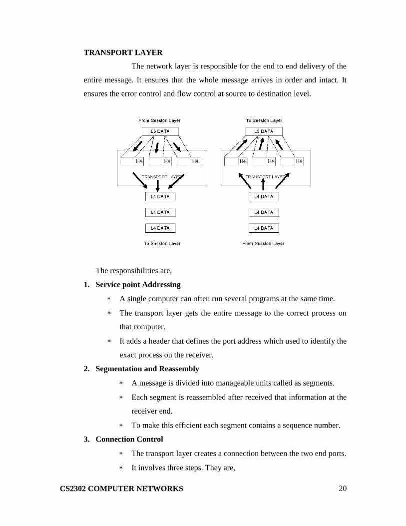
TRANSPORT LAYER
The network layer is responsible for the end to end delivery of the
entire message. It ensures that the whole message arrives in order and intact. It
ensures the error control and flow control at source to destination level.
The responsibilities are,
1. Service point Addressing
A single computer can often run several programs at the same time.
The transport layer gets the entire message to the correct process on
that computer.
It adds a header that defines the port address which used to identify the
exact process on the receiver.
2. Segmentation and Reassembly
A message is divided into manageable units called as segments.
Each segment is reassembled after received that information at the
receiver end.
To make this efficient each segment contains a sequence number.
3. Connection Control
The transport layer creates a connection between the two end ports.
It involves three steps. They are,

CS2302 COMPUTER NETWORKS
21
1. connection establishment
2. data transmission
3. connection discard
4. Flow Control
Flow control is performed at end to end level
5. Error Control
Error control is performed at end to end level.
SESSION LAYER
It acts as a dialog controller. It establishes, maintains and synchronizes the
interaction between the communication devices.
The responsibilities are,
1. Dialog Control
The session layer allows two systems to enter into a dialog.
It allows the communication between the devices.
2. Synchronization
It adds a synchronization points into a stream of bits.
PRESENTATION LAYER
The presentation layer is responsible for the semantics and the syntax of
the information exchanged.

CS2302 COMPUTER NETWORKS
22
The responsibilities are,
1. Translation
Different systems use different encoding systems.
The presentation layer is responsible for interoperability between
different systems.
The presentation layer t the sender side translates the information from
the sender dependent format to a common format. Likewise, at the
receiver side presentation layer translate the information from common
format to receiver dependent format.
2. Encryption
To ensure security encryption/decryption is used
Encryption means transforms the original information to another
form
Decryption means retrieve the original information from the
encrypted data
3. Compression
It used to reduce the number of bits to be transmitted.
APPLICATION LAYER
The application layer enables the user to access the network. It provides
interfaces between the users to the network.

CS2302 COMPUTER NETWORKS
23
The responsibilities are,
1. Network Virtual Terminal
It is a software version of a physical terminal and allows a user to log on
to a remote host.
2. File Transfer, Access, and Management
It allows a user to access files in a remote computer, retrieve files, and
manage or control files in a remote computer.
3. Mail Services
It provides distributed database sources and access for global information
about various objects and services.
INTERNET ARCHITECTURE
The internet architecture evolved out of experiences with an earlier packet
switched network called the ARPANET. Both the Internet and the ARPANET were
funded by the Advanced Research Projects Agency (ARPA).
The Internet and ARPANET were around before the OSI architecture, and the
experience gained from building them was a major influence on the OSI reference model.
Instead of having seven layers, a four layer model is often used in Internet.

CS2302 COMPUTER NETWORKS
24
At the lowest level are a wide variety of network protocols, denoted NET1, NET2
and so on. The second layer consists of a single protocol the Internet Protocol IP. It
supports the interconnection of multiple networking technologies into a single, logical
internetwork.
The third layer contains two main protocols the Transmission Control Protocol
(TCP) and User Datagram Protocol (UDP). TCP provides a reliable byte stream channel,
and UDP provides unreliable datagram delivery channel. They are called as end to end
protocol they can also be referred as transport protocols.
Running above the transport layer, a range of application protocols such as FTP,
TFTP, Telnet, and SMTP that enable the interoperation of popular applications.
ERROR
Networks must be able to transfer data from one device to another with complete
accuracy. Some part of a message will be altered in transit than that the entire content
will arrive intact. Many factors like line noise can alter or wipe out one or more bits of a
given data unit. This is known as errors.
TYPES OF ERRORS
There are two types. They are,
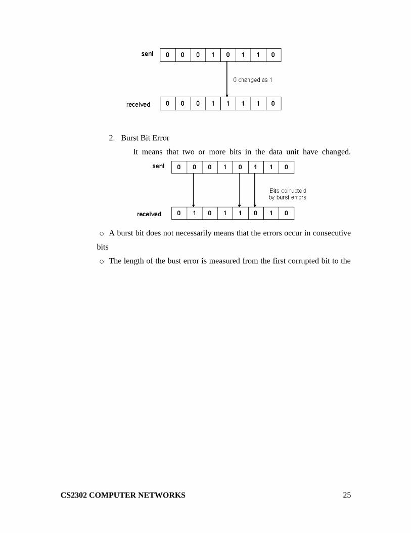
1. Single Bit Error
It means that only one bit of a given data unit is changed from 1 to
0 or from 0 to 1.
CS2302 COMPUTER NETWORKS
25
2. Burst Bit Error
It means that two or more bits in the data unit have changed.
o A burst bit does not necessarily means that the errors occur in consecutive
bits
o The length of the bust error is measured from the first corrupted bit to the

CS2302 COMPUTER NETWORKS
26
TYPES
VERTICAL REDUNDANCY CHECK:
It is also known as parity check. In this technique a redundant bit called a parity
bit is appended to every data unit so that the total number of 1s in the unit including the
parity bit becomes even for even parity or odd for odd parity.
In even parity, the data unit is passed through the even parity generator. It counts
the number of 1s in the data unit. If odd number of 1s, then it sets 1 in the parity bit to
make the number of 1s as even. If the data unit having even number of 1s then it sets in
the parity bit to maintain the number of 1s as even. When it reaches its destination, the
receiver puts all bits through an even parity checking function. If it counts even number
of 1s than there is no error. Otherwise there is some error.

CS2302 COMPUTER NETWORKS
27
EXAMPLE:
The data is : 01010110
The VRC check : 010101100
CS2302 COMPUTER NETWORKS
28
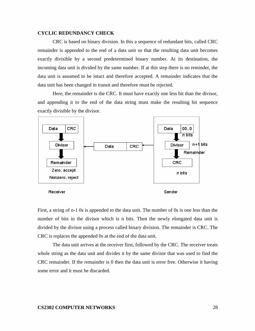
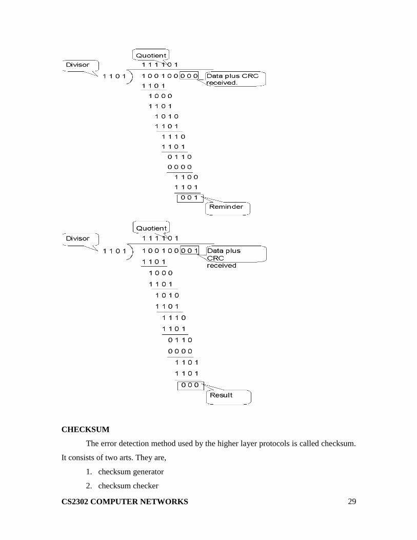
CYCLIC REDUNDANCY CHECK
CRC is based on binary division. In this a sequence of redundant bits, called CRC
remainder is appended to the end of a data unit so that the resulting data unit becomes
exactly divisible by a second predetermined binary number. At its destination, the
incoming data unit is divided by the same number. If at this step there is no reminder, the
data unit is assumed to be intact and therefore accepted. A remainder indicates that the
data unit has been changed in transit and therefore must be rejected.
Here, the remainder is the CRC. It must have exactly one less bit than the divisor,
and appending it to the end of the data string must make the resulting bit sequence
exactly divisible by the divisor.
First, a string of n-1 0s is appended to the data unit. The number of 0s is one less than the
number of bits in the divisor which is n bits. Then the newly elongated data unit is
divided by the divisor using a process called binary division. The remainder is CRC. The
CRC is replaces the appended 0s at the end of the data unit.
The data unit arrives at the receiver first, followed by the CRC. The receiver treats
whole string as the data unit and divides it by the same divisor that was used to find the
CRC remainder. If the remainder is 0 then the data unit is error free. Otherwise it having
some error and it must be discarded.
CS2302 COMPUTER NETWORKS
29
CHECKSUM
The error detection method used by the higher layer protocols is called checksum.
It consists of two arts. They are,
1. checksum generator
2. checksum checker
CS2302 COMPUTER NETWORKS
30
Checksum Generator:
In the sender, the checksum generator subdivides the data unit into equal
segments of n bits. These segments are added with each other by using one‟s complement
arithmetic in such a way that the total is also n bits long. That total is then complemented
and appended to the end of the data unit.
Checksum Checker:
The receiver subdivides the data unit as above and adds all segments together and
complements the result. If the extended data unit is intact, the total value found by adding
the data segments and the checksum field should be zero. Otherwise the packet contains
an error and the receiver rejects it.
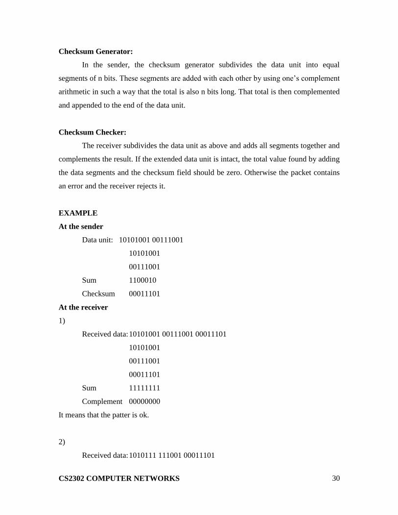
EXAMPLE
At the sender
Data unit: 10101001 00111001
10101001
00111001
Sum 1100010
Checksum 00011101
At the receiver
1)
Received data: 10101001 00111001 00011101
10101001
00111001
00011101
Sum 11111111
Complement 00000000
It means that the patter is ok.
2)
Received data: 1010111 111001 00011101

CS2302 COMPUTER NETWORKS
31
10101111
11111001
00011101
Result 11000101
Carry 1
Sum 11000110
Complement 00111001
It means that the patter is corrupted.
ERROR CORRECTION
Error correction is handled in two ways. In one, when an error is discovered, the
receiver can have the sender retransmit the entire data unit. In the other, a receiver can
use an error correcting code, which automatically corrects certain errors.
Types of error correction:
1. Single bit error correction
2. Burst bit error correction
Single Bit Error Correction
To correct a single bit error in an ASCII character, the error correction code must
determine which of the seven bits has changed. In this case we have to determine eight
different states: no error, error in position 1, error in position 2, error in position 3, error
in position 4, error in position 5, error in position 6, error in position 7. It looks like a
three bit redundancy code should be adequate because three bits can show eight different
states. But what if an error occurs in the redundancy bits? Seven bits of data and three
bits of redundancy bits equal 10 bits. So three bits are not adequate.
To calculate the number of redundancy bits (r) required to correct a given number
of data bits (m) we must find a relationship between m and r.
If the total number of bits in a transmittable unit is m+r then r must be able to
indicate at least m+r+1 different state. Of these, one state means no error and m+r states
indicate the location of an error in each of the m+r positions.
So m+r+1 state must be discoverable by r bits. And r bits can indicate 2r different
states. Therefore, 2r must be equal to or greater than m+r+1;
2r >=m+r+1

CS2302 COMPUTER NETWORKS
32
NUMBER OF DATA
BITS (M)
NUMBER OF
REDUNDANCY BITS (R) TOTAL BITS (M+R)
1 2 3
2 3 5
3 3 6
4 3 7
5 4 9
6 4 10
7 4 11
Hamming Code:
The hamming code can be applied to data units of any length and uses the
relationship between data and redundancy bits.
Positions of redundancy bits in hamming code
The combinations used to calculate each of the four r values for a seven bit data
sequence are as follows:
r1 :1,3,5,7,9,11
r2 : 2,3,6,7,10,11
r3 : 4,5,6,7
r4 : 8,9,10,11

CS2302 COMPUTER NETWORKS
33
Here, r1 bit is calculated using all bit positions whose binary representation
includes a 1 in the rightmost position (0001, 0011, 0101, 0111, 1001, and 1011). The r2
bit is calculated using all bit positions with a 1 in the second position (0010, 0011, 0110,
0111, 1010 and 1011), and for r3 1 at third bit position (0100, 0101, 0110 and 0111) for
r4 1 at fourth bit position (1000, 1001, 1010 and 1011).
Calculating the r Values:
In the first step, we place each bit of the original character in its appropriate
positions in the 11 bit unit. Then, we calculate the even parities for the various bit
combinations. The parity value of each combination is the value of the corresponding r
bit. For example r1 is calculated to provide even parity for a combination of bits 3, 5, 7,
9, 11.
Error Detection and Correction:
Example:
At the sender:
Data to be sent: 1001101
Redundancy bit calculation:
CS2302 COMPUTER NETWORKS
34
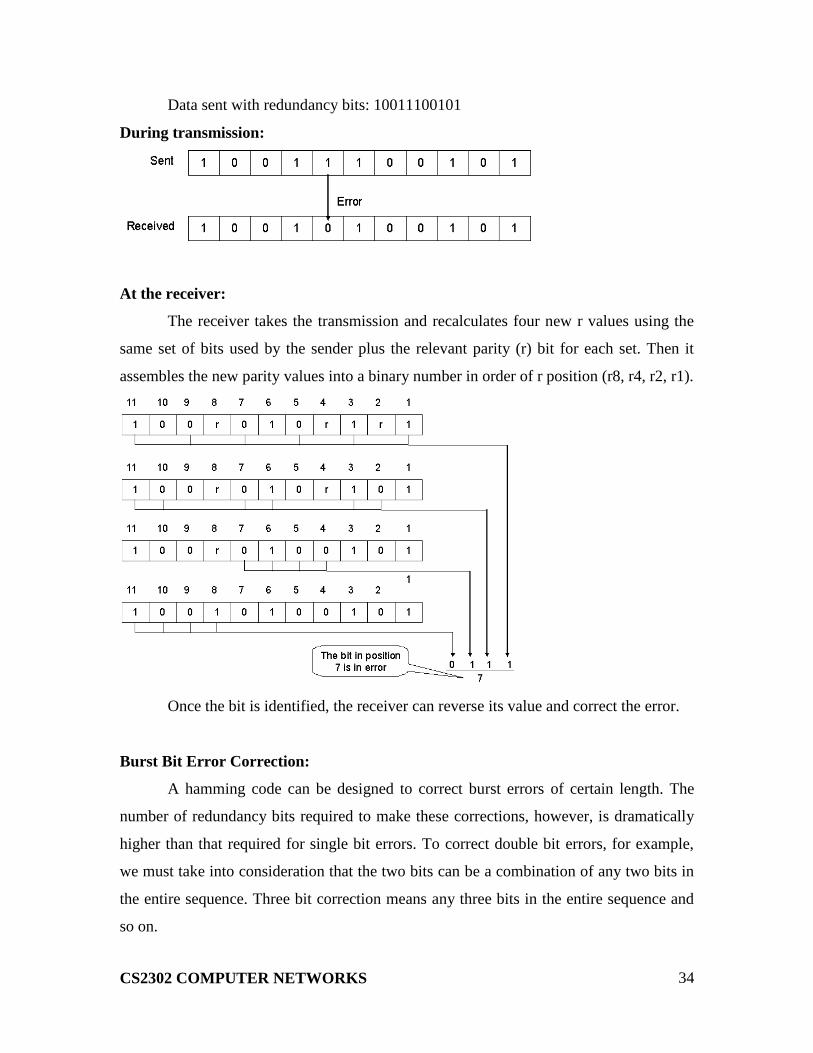
Data sent with redundancy bits: 10011100101
During transmission:
At the receiver:
The receiver takes the transmission and recalculates four new r values using the
same set of bits used by the sender plus the relevant parity (r) bit for each set. Then it
assembles the new parity values into a binary number in order of r position (r8, r4, r2, r1).
Once the bit is identified, the receiver can reverse its value and correct the error.
Burst Bit Error Correction:
A hamming code can be designed to correct burst errors of certain length. The
number of redundancy bits required to make these corrections, however, is dramatically
higher than that required for single bit errors. To correct double bit errors, for example,
we must take into consideration that the two bits can be a combination of any two bits in
the entire sequence. Three bit correction means any three bits in the entire sequence and
so on.
CS2302 COMPUTER NETWORKS
35
FUNCTIONS OF DATA LINK LAYER:
The data link layer is responsible for the following functions. They are,
1. Line discipline or Access control
2. Flow control
3. Error control
4. Framing
LINE DISCIPLINE
Communications requires at least two devices, one to send and one to receive. If
both devices are ready to send some information and put their signals on the link then the
two signals collides each other and became nothing. To avoid such a situation the data
link layer use a mechanism called line discipline.
Line discipline coordinates the link system. It determines which device can send
and when it can send. It answers then question, who should send now?
Line discipline can serve in two ways:
1. enquiry / acknowledgement (ENQ / ACK)
2. poll / select (POLL / SELECT)
ENQ / ACK:
This method is used in peer to peer communications. That is where there is a
dedicated link between two devices.
The initiator first transmits a frame called an enquiry (ENQ) asking I the receiver
is available to receive data. The receiver must answer either with an acknowledgement
(ACK) frame if it ready to accept or with a negative acknowledgement (NAK) frame if it
is not ready. If the response is positive, the initiator is free to send its data. Otherwise it
waits, and try again. Once all its data have been transmitted, the sending system finishes
with an end of transmission (EOT) frame.

CS2302 COMPUTER NETWORKS
36
POLL / SELECT
When the primary ready to receive data, it must ask (poll) each device in turn if it
has anything to send. If the secondary have data to transmit it sends the data frame
otherwise sends a negative acknowledgment (NAK).

CS2302 COMPUTER NETWORKS
37
The primary then polls the next secondary. When the response is positive (a data
frame), the primary reads the frame and returns an acknowledgment (ACK).
There are two possibilities to terminate the transmission: either the secondary
sends all data, finishing with an EOT frame, or the primary says “timer‟s up”. Then the
primary cal polls the remaining devices.
SELECT:
This mode of function is used whenever the primary device has something to
send. It alerts the intended secondary device get ready to receive data. Before sending
data it sends the select (SEL) frame. The receiver returns an ACK frame. Then the
primary sends data.

CS2302 COMPUTER NETWORKS
38
FLOW CONTROL AND ERROR CONTROL
FLOW CONTROL
It refers to a set of procedures used to restrict the amount of data flow between
sending and receiving stations. It tells the sender how much data it can transmit before it
must wait for an acknowledgement from the receiver.
There are two methods are used. They are,
1. stop and wait
2. sliding window
STOP AND WAIT:
In this method the sender waits for acknowledgment after every frame it sends.
Only after an acknowledgment has been received, then the sender sends the next frame.
The advantage is simplicity. The disadvantage is inefficiency.

CS2302 COMPUTER NETWORKS
39
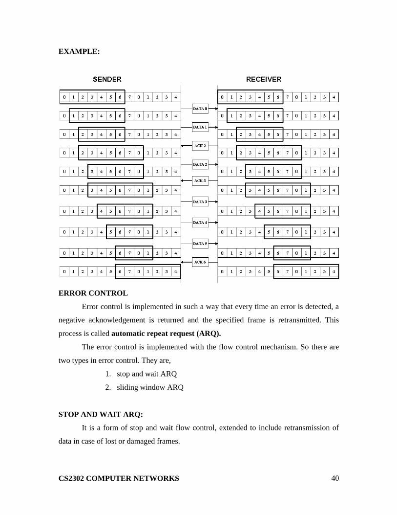
SLIDING WINDOW:
In this method, the sender can transmit several frames before needing an
acknowledgment. The receiver acknowledges only some of the frames, using a single
ACK to confirm the receipt of multiple data frames.
The sliding window refers to imaginary boxes at both the sender and receiver.
This window provides the upper limit on the number of frames that can be transmitted
before requiring an acknowledgement. To identify each frame the sliding window scheme
introduces the sequence number. The frames are numbered as 0 to n-1. And the size of
the window is n-1. Here the size of the window is 7 and the frames are numbered as
0,1,2,3,4,5,6,7.
CS2302 COMPUTER NETWORKS
40
EXAMPLE:
ERROR CONTROL
Error control is implemented in such a way that every time an error is detected, a
negative acknowledgement is returned and the specified frame is retransmitted. This
process is called automatic repeat request (ARQ).
The error control is implemented with the flow control mechanism. So there are
two types in error control. They are,
1. stop and wait ARQ
2. sliding window ARQ
STOP AND WAIT ARQ:
It is a form of stop and wait flow control, extended to include retransmission of
data in case of lost or damaged frames.

CS2302 COMPUTER NETWORKS
41
DAMAGED FRAME:
When a frame is discovered by the receiver to contain an error, it returns a
NAK frame and the sender retransmits the last frame.
LOST DATA FRAME:
The sender is equipped with a timer that starts every time a data frame is
transmitted. If the frame lost in transmission the receiver can never acknowledge it. The
sending device waits for an ACK or NAK frame until its timer goes off, then it tries
again. It retransmits the last data frame.
CS2302 COMPUTER NETWORKS
42
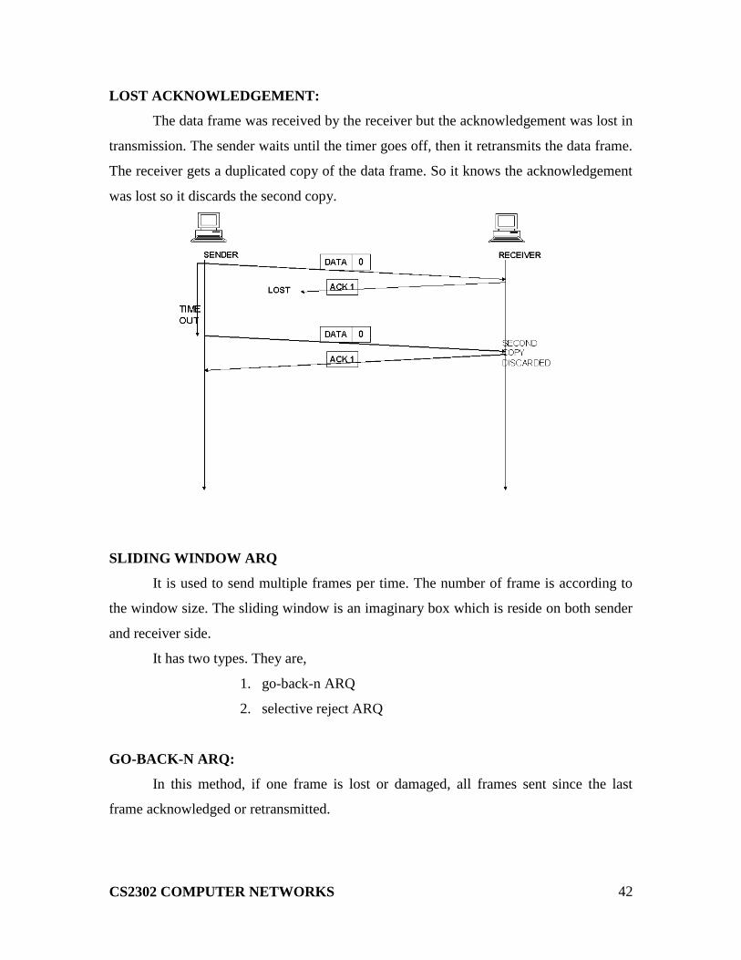
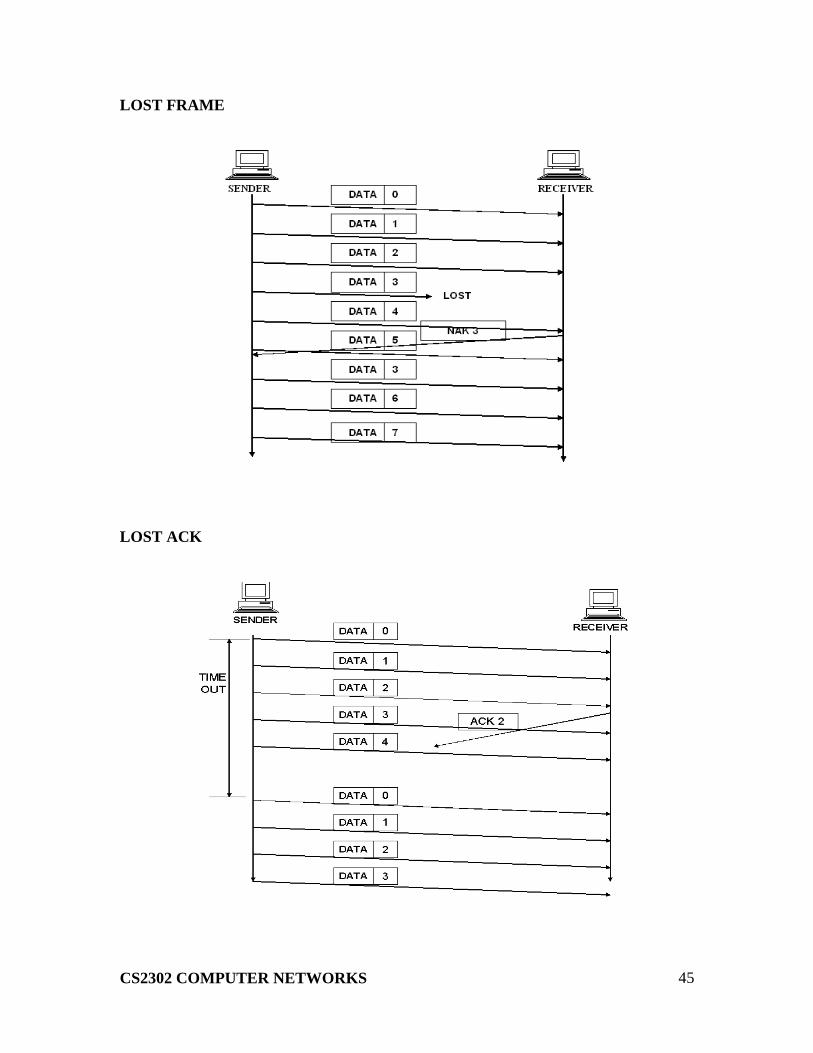
LOST ACKNOWLEDGEMENT:
The data frame was received by the receiver but the acknowledgement was lost in
transmission. The sender waits until the timer goes off, then it retransmits the data frame.
The receiver gets a duplicated copy of the data frame. So it knows the acknowledgement
was lost so it discards the second copy.
SLIDING WINDOW ARQ
It is used to send multiple frames per time. The number of frame is according to
the window size. The sliding window is an imaginary box which is reside on both sender
and receiver side.
It has two types. They are,
1. go-back-n ARQ
2. selective reject ARQ
GO-BACK-N ARQ:
In this method, if one frame is lost or damaged, all frames sent since the last
frame acknowledged or retransmitted.

CS2302 COMPUTER NETWORKS
43
DAMAGED FRAME:
LOST FRAME:
CS2302 COMPUTER NETWORKS
44
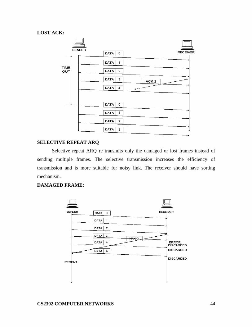
LOST ACK:
SELECTIVE REPEAT ARQ
Selective repeat ARQ re transmits only the damaged or lost frames instead of
sending multiple frames. The selective transmission increases the efficiency of
transmission and is more suitable for noisy link. The receiver should have sorting
mechanism.
DAMAGED FRAME:
CS2302 COMPUTER NETWORKS
45
LOST FRAME
LOST ACK

CS2302 COMPUTER NETWORKS
46
FRAMING
The sream of bits are not advisible to mqaintain in networks. When an error
occurs, then the entire stream have to retransmitted. To avoid this, the framing concept is
used. In this, the stream of bits are divided into manageable bit units called frames. To
achive, we are using several ways. They are,
1. Byte Oriented Protocols
2. Bit Oriented Protocols
3. Clock Based Protocols
1. BYTE ORIENTED PROTOCOLS:
Each frame is considered as a collection of bytes rather than a collection of bits.
There are two approaches. They are,
1. Sentinel approach
In this approach it uses special characters called sentinel characters
to indicate where frames start and end. This approach is called character stuffing because
extra characters are inserted in the data portion of the frame.
Ex: 1. Binary Synchronous Communication (BISYNC)
2. Point to Point Protocol
2. Byte Count Approach
In this approach no of bytes in frame are counted and entered in
the header. The COUNT Field specifies how many bytes are contained in the frame‟s
body.
Ex: 1.Digital Data Communication Message Protocol
2. BIT ORIENTED PROTOCOLS:
It views the frames as a collection of bits. The Synchronous Data Link Control
(SDLC) protocol developed by IBM is an example of a bit oriented protocol. It was later
standardized by the ISO as the High Lever Data Link Control (HDLC)
HDLC – HIGH LEVEL DATA LINK CONTROL
It is a bit oriented data link protocol designed to support both half duplex and full
duplex communication over point to point and multi point links.

CS2302 COMPUTER NETWORKS
47
FRAME FORMAT
HDLC denotes both the beginning and the end of a frame with the distinguished bit
sequence 01111110. To guarantee that a special sequence does not appear in advertently
anywhere else in the frame, HDLC uses a process called bit stuffing.
On the sending side, any time five consecutive 1s have been transmitted from the
body of the message, the sender inserts a 0 before transmitting the next bit. On the receiver
side, should five consecutive 1s arrive, the receiver makes its decision based on the next
bit it sees. If the next bit is a 1, then one of the two things is true. Either this is the end of
the frame or an error has been introduced. By looking at the next bit, it can conclude. If it
sees a 0, then it is the end of frame. It else, then there must have an error and the whole
frame has been discarded.
3. CLOCK BASED PROTOCOLS:
The Synchronous Optical NETwork (SONET) is one of the protocols using the
clock based framing approach.
SONET:
It was developed by the ANSI for digital transmission over optical network. It
addresses both the framing and encoding problems. A SONET frame has some special
information to distinguish where the frame starts and ends.

CS2302 COMPUTER NETWORKS
48
CS2302 COMPUTER NETWORKS
UNIT II
Medium access – CSMA – Ethernet – Token ring – FDDI - Wireless LAN – Bridges and
Switches
ETHERNET (802.3):
The Ethernet is developed in the mid-1970 by researches at the Xerox Palo Alto
Research Center (PARC); the Ethernet is a working example of the more general carrier
sense, multiple accesses with collision detect (CSMA/CD) local area network technology.
The “carrier sense” in CSMA/CD means that all the nodes can distinguish between
an idle and a busy link, and “collision detect” means that all the nodes listens as it transmits
and can therefore detect when a frame it is transmitting has interfered (collided) with a
frame transmitted by another node.
PHYSICAL PROPERTIES:
An Ethernet segment is implemented on a coaxial cable of up to 500m. this cable
is similar to the type used for cable TV, except that it typically has an impedance of 50
ohms instead of cable TV‟s 75 ohms. Hosts connect to an Ethernet segment by tapping
into it; taps must be at least 2.5 m apart.
A transceiver a small device directly attached to the tap detects when the line is
idle and drives the signal when the host is transmitting. It also receives incoming signals.
The transceiver is, in turn, connected to an Ethernet adaptor, which is plugged into the
host.

CS2302 COMPUTER NETWORKS
49
Multiple Ethernet segments can be joined together by repeater. A repeater is a
device that forwards digital signals, much like an amplifier forwards analog signals.
However, no more than four repeaters may be positioned between any pair of hosts,
meaning that an Ethernet has a total reach of only 2,500m.
An Ethernet is limited to supporting a maximum of 1,024 hosts. Terminators
attached to the end of each segment absorb the signal and keep it from bouncing back and
interfering with trailing signals.
STANDARDS:
There are various standards of Ethernet are,
10Base5:
The first of the physical standards defined in the IEEE 802.3 model is called 10Base5.It is
also known as thick net or thick Ethernet. A segment of the original 10Base5 cable can be
up to 500m long.
10Base2:
The second implementation defined by the IEEE892 series is called 10Base2.It also
known as thin-net, cheapnet, cheapernet, thinwire Ethernet or thin Ethernet. In this “10”
means the network operates at 10 Mbps, “Base” refers to the fact that the cable is used in
a base band system and the “2” means that a given segment can be no longer than 200m
10BaseT:
The most popular standard defined in the IEEE 802.3 series is 10BaseT. It is also known
as twisted pair Ethernet. The “T” stands for twisted pair. A 10BaseT segment is usually
limited to less than 100m in length.
ACCESS CONTROL:
This algorithm is commonly called the Ethernet‟s media access control (MAC). It is
typically implemented in hardware on the network adaptor.
FRAME FORMAT:

CS2302 COMPUTER NETWORKS
50
Preamble allows the receiver to synchronize with the signal. Both the source and
destination hosts are identified with a 48-bit address. Each frame contains up to 1,500
bytes of data. A frame must contain at least 46 bytes of data, even if this means the host
has to pad the frame before transmitting it. Each frame includes a 32-bit CRC.
ADDRESSES:
It is usually burned into ROM. Ethernet addresses are typically printed in a form
humans can read as a sequence of six numbers separated by colons.
Each number corresponds to 1 byte of the 6-byte address and is given by a pair of
hexadecimal digits, one for each of the 4-bit nibbles in the byte; leading 0s are dropped.
To ensure that every adaptor gets a unique address, each manufacturer of Ethernet
devices is allocated a different prefix that must be prep-ended to the address on every
adaptor they build.
UNICAST : Addresses are used to send messages to specific device.
MULTICAST : Addresses are used to send messages to group of devices.
BROADCAST : address are just used to send messages in the network who
are in the need of messages can use it.
TRANSMITTER ALGORITHM:
The receiver side of the Ethernet protocol is simple; the real smarts are
implemented at the sender‟s side. The transmitter algorithm is defined as follows:
When the adaptor has a frame to send and the line is busy, it waits for the line to go idle
and then transmits immediately.
The Ethernet is said to be a 1-persistent protocol because an adaptor with a frame
to send transmits with probability 0<=p<=1 after a line becomes idle, and defers with
probability q=1-p. Because there is no centralized control it is possible for two (or more)
adaptors to begin transmitting at the same time, either because both found the line to be
idle or because both had been waiting for a busy line to become idle.
When this happens, the two (or more) frames are said to collide on the network.
Each sender, because the Ethernet supports collision detection, is able to determine that a
collision is in progress. At the moment an adaptor detects that is frame is colliding with
another, it first makes sure to transmit a sure to transmit a 32-bit jamming sequence and
then stops the transmission.

CS2302 COMPUTER NETWORKS
51
Thus, a transmitter will minimally send 96 bits in the case of a collision: 64-bit
preamble plus 32-bit jamming sequence. One way that an adaptor will send only 96-bits
which is sometimes called a runt frame is if the two hosts are close to each other. Had the
two hosts been farther apart, they would have had to transmit longer, and thus send more
bits, before detecting the collision.
In fact, the worst-case scenario happens when the two hosts are at opposite ends of
the Ethernet. To know for sure that the frame it just sent did not collide with another
frame, the transmitter may need to send as many as 512 bits.
Not coincidentally, every Ethernet frame must be at least 512 bits (64 bytes)long: 14 bytes
of header plus 46 bytes of data plus 4 bytes of CRC.
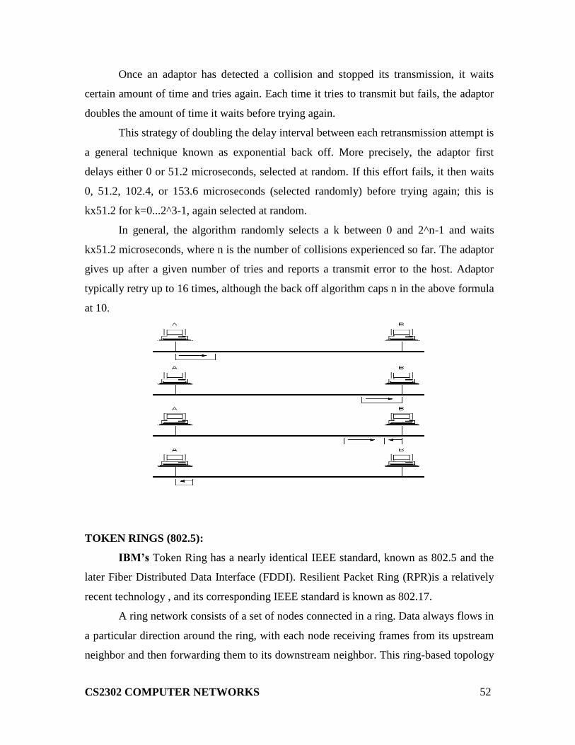
Where hosts A and B are at opposite ends of the network. Suppose host A begins
transmitting a frame at time t, as shown in (a). it takes it one link latency (let‟s denote the
latency as d) for the frame to reach host B.
Thus, the first bit of A‟s frame arrives at B at time t+d, as shown in (b). Suppose an
instant before host A‟s frame arrives (i.e., B still sees and idle line), host B begins to
transmit its own frame.
B‟s frame will immediately collide with A‟s frame, and this collision will be
detected by host B(c). host B will send the 32-bit jamming sequence, as described
above.(B‟s frame will be a runt).
Unfortunately, host A will not know that the collision occurred until B‟s frame
reaches it, which will happen one link latency later, at time t+2xd, as shown in (d). Host A
must continue to transmit until this time in order to detect the collision. In other words,
host A must transmit for 2xd should be sure that it detects all possible collisions.
Considering that a maximally configured Ethernet is 2,500 m long, and that there
may be up to four repeaters between any two hosts, the round-trip delay has been
determined to be 51.2 microseconds, which on a 10-Mbps Ethernet corresponds to 512
bits.
The other way to look at this situation is that we need to limit the Ethernet‟s
maximum latency to a fairly small value (e.g., 512micro seconds) for the access algorithm
to work; hence, an Ethernet‟s maximum length must be something on the order of
2,500m.
CS2302 COMPUTER NETWORKS
52
Once an adaptor has detected a collision and stopped its transmission, it waits
certain amount of time and tries again. Each time it tries to transmit but fails, the adaptor
doubles the amount of time it waits before trying again.
This strategy of doubling the delay interval between each retransmission attempt is
a general technique known as exponential back off. More precisely, the adaptor first
delays either 0 or 51.2 microseconds, selected at random. If this effort fails, it then waits
0, 51.2, 102.4, or 153.6 microseconds (selected randomly) before trying again; this is
kx51.2 for k=0...2^3-1, again selected at random.
In general, the algorithm randomly selects a k between 0 and 2^n-1 and waits
kx51.2 microseconds, where n is the number of collisions experienced so far. The adaptor
gives up after a given number of tries and reports a transmit error to the host. Adaptor
typically retry up to 16 times, although the back off algorithm caps n in the above formula
at 10.
TOKEN RINGS (802.5):
IBM’s Token Ring has a nearly identical IEEE standard, known as 802.5 and the
later Fiber Distributed Data Interface (FDDI). Resilient Packet Ring (RPR)is a relatively
recent technology , and its corresponding IEEE standard is known as 802.17.
A ring network consists of a set of nodes connected in a ring. Data always flows in
a particular direction around the ring, with each node receiving frames from its upstream
neighbor and then forwarding them to its downstream neighbor. This ring-based topology

CS2302 COMPUTER NETWORKS
53
is in contrast to the Ethernet‟s bus topology. Like the Ethernet, however, the ring-based
topology is viewed as a single shared medium; it does not behave as a collection of
independent point to point links that just happen to be configured in a loop. Thus, a ring
networks shares two key features with an Ethernet:
First, it involves a distributed algorithm that controls when each node is allowed to
transmit and second all nodes typically see all frames, with the node identified in the
frame header as the destination saving a copy of the frame as it flows past.
The most common early forms of ring network were all token rings. The word
“token” comes from the way access to the shared ring is managed. The idea is that a
token, which is really just a special sequence of bits, circulates around the ring; each node
receives and then forwards the token.
When a node that has a frame to transmit sees the token, it takes the token off the
ring (i.e it does not forward the special bit pattern ) and instead inserts its frame into the
ring. Each node along the way simply forwards the frame, with the destination node
saving a copy and forwarding the message onto the next node on the ring. When the frame
makes its way back around to the sender, this node strips its frame off the ring (rather than
continuing to forward it) and reinserts the token.
In this way, some node downstream will have the opportunity to transmit a frame.
The media access algorithm is fair in the sense that as the token circulates around the ring,
each node gets a chance to transmit. Nodes are serviced in a round-robin fashion.

CS2302 COMPUTER NETWORKS
54
The problem of node failure may be addressed by connecting each station into the ring
using an electromechanical relay. As long as the station is healthy, the relay is open and
the station is included in the ring. If the station stops providing the power, the relay closed
and the ring automatically by passes the station.
Several of these relays are usually packed into a single box, known as multistation
access unit (MSAU). This has the interesting effect of making a token ring actually look
more like a star topology.
CS2302 COMPUTER NETWORKS
55
TOKEN RING MEDIA ACCESS CONTROL:
The network adaptor for a token ring contains a receiver and a transmitter. When a
node is neither the source not the destination of the data on the ring, its adaptor is simply
retransmitting the data that its receiver receives. When none of the stations connected to
the ring has anything to send, the token circulates around the ring. As it does so, any
station that has data to send may “seize” the token, that is not retransmit it and begin
sending data. Once a station has the token, it is allowed to send one or more packets.
How long a given node is allowed to hold the token: the token holding time (THT)? The
priority of the token changes over time due to the use of three reservation bits in the frame
header.
The 802.5 protocol provides a form of reliable delivery using 2 bits in the packet
trailer, the A and C bits. These are both 0 initially. When a station sees a frame for which
it is the intended recipient, is not functioning or absent. If the A bit is set but not the C bit,
this implies that for some reason, the destination could not accept the frame. Thus, the
frame might reasonably be retransmitted later in the hope that buffer space had become
available.
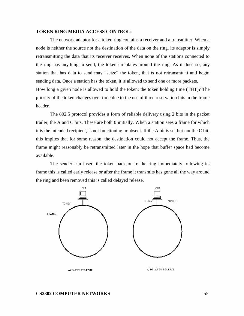
The sender can insert the token back on to the ring immediately following its
frame this is called early release or after the frame it transmits has gone all the way around
the ring and been removed this is called delayed release.
CS2302 COMPUTER NETWORKS
56
TOKEN RING MAINTENANCE:
Each 802.5 token ring has one station designated as a monitor. The monitor‟s job
is to ensure the health of the ring by, for example, making sure that the token is not lost.
Any station on the ring can become the monitor, and there are defined procedures by
which the monitor is elected when the ring is first connected or on the failure of the
current monitor. A healthy monitor periodically announces its presence with a special
control message; if a station fails to see such a message for some period of time, it will
assume that the monitor has failed and will try to become the monitor. The procedures for
electing a monitor are the same whether the ring has just come up or the active monitor
has just failed.
When a station decides that a new monitor is needed, it transmits a “claim token”
frame, announcing its intent to become the new monitor. If that token circulates back to
the sender, it can assume that it is okay for it to become the monitor. If some other station
is also trying to become the monitor at the same instant, the sender might see a claim
token message from that other station first. In this case, it will be necessary to break the
tie using some well –defined rule like “highest address wins”.
One responsibility of the monitor is to make sure that there is always a token
somewhere in the ring, either circulating or currently held by a station. It should be clear
that a token may vanish for several reasons, such as a bit error, or a crash on the part of a
station that was holding it. To detect a missing token, the monitor watches for a passing
token and maintains a timer equal to the maximum possible token rotation time. This
interval equals
Numstation x THT + RingLatency
Where Numstation is the number of stations on the ring, and RingLatency is the
total propagation delay of the ring. If the timer expires without the monitor seeing a token,
it creates a new one.
The monitor also checks for corrupted or orphaned frames. The former have
checksum errors or invalid formats, and without monitor intervention, they could circulate
forever on the ring.
The monitor drains them off the ring before reinserting the token. An orphaned
frame is one that was transmitted correctly onto the ring but whose” parent” died, that is ,
CS2302 COMPUTER NETWORKS
57
the sending station went down before it could remove the frame from the ring. These are
detected using another header bit, the “monitor” bit. This is 0 on transmission and set to 1
the first time the packet passes the monitor. If the monitor sees a packet with this bits set,
it knows the packet is going by for the second time and it drains the packet off the ring.
If any station suspects a failure on the ring, it can send a beacon frame to the suspect
destination. Based on how far this frame gets, the status of the ring can be established, and
malfunctioning stations can be bypassed by the relays in the MASU.
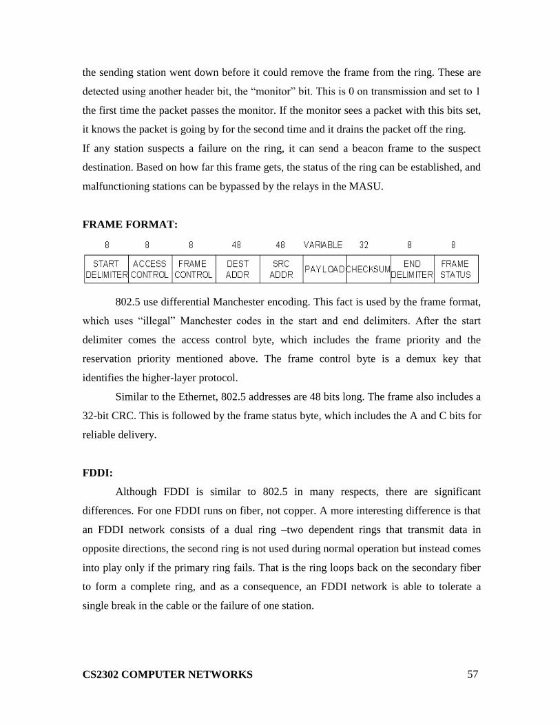
FRAME FORMAT:
802.5 use differential Manchester encoding. This fact is used by the frame format,
which uses “illegal” Manchester codes in the start and end delimiters. After the start
delimiter comes the access control byte, which includes the frame priority and the
reservation priority mentioned above. The frame control byte is a demux key that
identifies the higher-layer protocol.
Similar to the Ethernet, 802.5 addresses are 48 bits long. The frame also includes a
32-bit CRC. This is followed by the frame status byte, which includes the A and C bits for
reliable delivery.
FDDI:
Although FDDI is similar to 802.5 in many respects, there are significant
differences. For one FDDI runs on fiber, not copper. A more interesting difference is that
an FDDI network consists of a dual ring –two dependent rings that transmit data in
opposite directions, the second ring is not used during normal operation but instead comes
into play only if the primary ring fails. That is the ring loops back on the secondary fiber
to form a complete ring, and as a consequence, an FDDI network is able to tolerate a
single break in the cable or the failure of one station.

CS2302 COMPUTER NETWORKS
58
Another interesting difference is that instead of designating one node as a monitor,
all the nodes participate equally in maintaining the FDDI ring. Each node maintains an
estimate of the token rotation time (TRT) the expected maximum time for the token to
make one complete trip around the ring. A node then measures the time between
successive arrivals of the token. If too much time elapses, suggesting that the token has
been lost, the node transmits a “claim frame” in which it includes its current TRT
estimate. The claim serves two functions. First, the claim frame is vote for a particular
value of the TRT. Any node that wants to vote for a shorter TRT will replace that claim
frame with its own claim frame; otherwise it will accept the new time and forward the
claim frame. Second, the claim frame is a request for authorization to regenerate the
token. If a claim frame makes it all the way back around to the original sender, that node
knows not only that the TRT it voted for was the shortest and has been accepted by all the
other nodes, but also that it has been authorized to regenerate the token.
When the token arrives at a node with time to spare the node can transmit data so
long as it does not make the token fall behind schedule, otherwise the node cannot
transmit data. A shortcoming of this basic scheme is that it cannot guarantee any
particular node the opportunity to transmit regularly, even if that node has data that is
sensitive to jitter, because an upstream node could consume all the available time. To
account for this possibility FDDI defines two classes of traffic:
Synchronous
CS2302 COMPUTER NETWORKS
59
Asynchronous
When a node receives a token, it is always allowed to send synchronous data, without
regard for whether the token is early or late. In contrast, a node can send asynchronous
traffic only when the token is early.
WIRELESS:
Wireless technologies differ in variety of dimensions, most notably in how much
bandwidth they provide and how far apart communicating nodes can be. Other important
differences include which part of the electromagnetic spectrum they use (including
whether it requires a license) and how much power they consume. Four prominent
wireless technologies:
► Blue tooth
► Wi-Fi(more formally known as 802.11)
► WiMAX(802.16)
► Third generation or 3Gcellular wireless.
The most widely used wireless links today are usually asymmetric, that is, the two
endpoints are usually different kinds of nodes.
BASE STATION, usually has no mobility, but has a wired (or at least high
bandwidth) connection to the internet or other networks.
A “client node” is often mobile, and relies on its link to the base station for all its
communication with other nodes. Wireless communication naturally supports point to
multipoint communication, because radio waves sent by one device can be simultaneously
received by many devices. However, it is often useful to create a point to point link
abstraction for higher layer protocols.
This topology implies three qualitatively different levels of mobility. The first
level is no mobility, such as when a receiver must be in a fixed location to receive a
directional transmission from the base station, as is the case with the initial version of
WiMAX. The second level is mobility within the range of a base, as is the case with
Bluetooth. The third level is mobility between bases, as is the case with cell phones and
Wi-Fi.
CS2302 COMPUTER NETWORKS
60
WI-FI (802.11):
This section takes a closer look at a specific technology centered on the emerging
IEEE 802.11 standard, also known as Wi-Fi. Wi-Fi is technically a trademark, owned by a
trade group called the Wi-Fi alliance that certifies product compliance with 802.11.
802.11 is designed for use in a limited geographical area (homes, office buildings,
campuses) and its primarily challenge is to mediate access to a shared communication
medium in this case, signals propagating through space.
PHYSICAL PROPERTIES:
802.11 run over six different physical layer protocols. Five are based on spread
spectrum radio, and one on diffused infrared (and is of historical interest only at this
point). The fastest runs at a maximum of 54 Mbps.
The original 802.11 standard defined two radio based physical layers standards,
one using frequency hopping and the other using direct sequence. Both provide up to 2
Mbps. Then physical layer standard 802.11 b was added. Using a variant of direct exempt
2.4GHz frequency band of the electromagnetic spectrum. Then came 802.11a, which
delivers up to 54 Mbps using a variant of FDM called orthogonal frequency division
multiplexing (OFDM). 802.11 a runs in the license-exempt 5GHz band. The most recent
standard is 802.11g, which is backward compatible with 802.11b.
COLLISION AVOIDANCE:
A wireless protocol wait until the link becomes idle before transmitting and back
off should a collision occur. Consider the situation where A and C are both within range
of B but not each other. Suppose both A and C want to communicate with B and so they
each send it a frame. A and C are unaware of each other since their signals do not carry
that far. These two frames collide with each other at B, but unlike an Ethernet, neither A
or C is aware of this collision. A and C are said to be hidden nodes with respect to each
other.
CS2302 COMPUTER NETWORKS
61
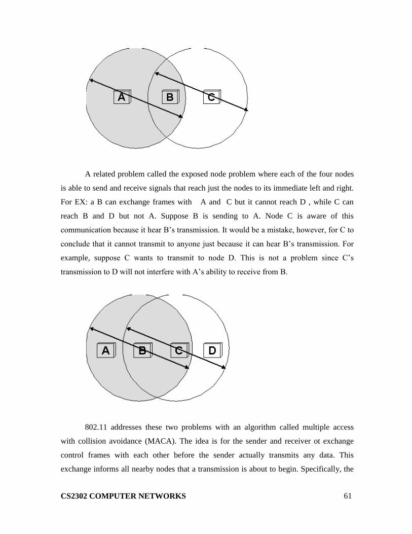
A related problem called the exposed node problem where each of the four nodes
is able to send and receive signals that reach just the nodes to its immediate left and right.
For EX: a B can exchange frames with A and C but it cannot reach D , while C can
reach B and D but not A. Suppose B is sending to A. Node C is aware of this
communication because it hear B‟s transmission. It would be a mistake, however, for C to
conclude that it cannot transmit to anyone just because it can hear B‟s transmission. For
example, suppose C wants to transmit to node D. This is not a problem since C‟s
transmission to D will not interfere with A‟s ability to receive from B.
802.11 addresses these two problems with an algorithm called multiple access
with collision avoidance (MACA). The idea is for the sender and receiver ot exchange
control frames with each other before the sender actually transmits any data. This
exchange informs all nearby nodes that a transmission is about to begin. Specifically, the
CS2302 COMPUTER NETWORKS
62
sender transmits a Request to send (RTS) frame to the receiver; the RTS frame includes a
field that indicates how long the sender wants to hold the medium. The receiver then
replies with a clear to send (CTS) frame. This frame echoes this length field back to the
sender. Any node that sees the RTS frame will collide with each other.
802.11 does not support collision detection, but instead the senders realize the in
which case they each wait a random amount of time before trying again. The amount of
time a given node delay is defined by the same exponential backoff algorithm used on the
Ethernet.
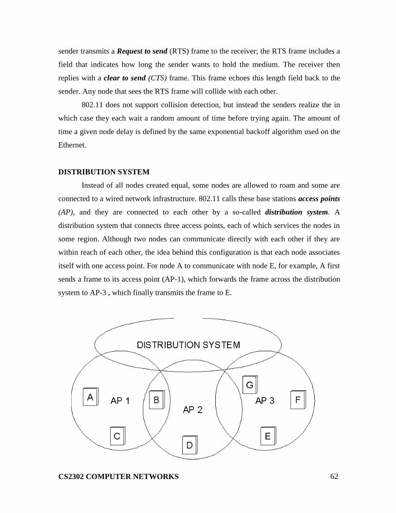
DISTRIBUTION SYSTEM
Instead of all nodes created equal, some nodes are allowed to roam and some are
connected to a wired network infrastructure. 802.11 calls these base stations access points
(AP), and they are connected to each other by a so-called distribution system. A
distribution system that connects three access points, each of which services the nodes in
some region. Although two nodes can communicate directly with each other if they are
within reach of each other, the idea behind this configuration is that each node associates
itself with one access point. For node A to communicate with node E, for example, A first
sends a frame to its access point (AP-1), which forwards the frame across the distribution
system to AP-3 , which finally transmits the frame to E.

CS2302 COMPUTER NETWORKS
63
The technique for selecting an AP is called scanning and involves the following four
steps:
1. The node sends a probe frame;
2. All APs within reach reply with a probe Response frames;
3. The node selects one of the access points, and sends that AP an Association
Request frames;
4. The AP replies with an Association Response frame.
Because the signal from its current AP has weakened due to the node moving away
from it. Whenever a node acquires a new AP, the new AP notifies the old AP of the
change via the distribution system.
Here in this fig., where node C moves from the cell serviced by AP-1 to the cell
serviced by AP-2.At some point, C prefers AP-2 over AP-1,and so it associates itself with
that access point.
The mechanism just described is called active scanning since the node is actively
searching for an access point. APs also periodically send a BEACON frame that the
capabilities of the access point; these include the transmission rates supported by the AP.
This is called passive scanning, and a node can change to this AP based on the
BEACON frame simply by sending an ASSOCIATION REQUEST frame back to the
access point.
FRAME FORMAT:
The frame contains the source and destination node address, each of which is 48
bits long, up to 2,312 bytes of data, and a 32-bit CRC. The Control field contains three
subfields of interest : a 6-bit Type field that indicates whether the frame carries data, is an
RTS or CTS frame, or is being used by the scanning algorithm; and a pair of 1-bit fields-
called ToDS and .

CS2302 COMPUTER NETWORKS
64
The 802.11 frame format is that it contains four, rather than two, address. how
these address are interpreted depends on the settings of the ToDS and FromDS bits in the
frame‟s Control field. This is to account for the possibility that the frame had to be
forwarded across the distribution systems, which would mean that the original sender is
not necessarily the same as the most recent transmitting node.
Similar reasoning applies to the destination address. In the simplest case, when
one node is sending directly to another, the DS bits are 0, Addr1 identifies the target node,
and Addr2 identifies the source node.
In the most complex case, both DS bits are set to 1, indicating that the message
went from a wireless node onto the distribution system and then from the distribution
system to another wireless node. With both bits set, Addr1 identifies the ultimate
destination, Addr2 identifies the immediate sender (the one that forwarded the frame from
the distribution system to the ultimate destination), Addr3 identifies the intermediate
destination (the one that accepted the frame from a wireless node and forwarded it across
the distribution system), and Addr4 identifies the original source. In terms of the example
given in fig., Addr1 corresponds to E, Addr2 identifies AP-3, Addr3 corresponds to AP-1,
and Addr4 identifies A.
CONNECTING DEVICES:
Networking and internetworking devices are classified into four categories:
repeaters, bridges, routers, and gateways.

CS2302 COMPUTER NETWORKS
65
BRIDGES AND LAN SWITCHES:
It is a node that forward frames from one Ethernet to the other. This node would
be in promiscuous mode, accepting all frames transmitted on either of the Ethernets, so it
could forward them to the other. A bridge is connected between two LANs with port. By
using the port number the LANs are addressed. Connected LANs are known as extended
LAN
LEARNING BRIDGES:
Bridges maintains a forwarding table which contains each host with their port
number. Having a human maintain this table is quite a burden, so a bridge can learn this
information for itself. The idea is for each bridge to inspect the source address in all the
frames it receives. When a bridge first boots, this table is empty; entries are added over
time. Also a timeout is associated with each entry and the bridge is cards the entry after a
specified period of time.
HOST PORT
A 1
B 1
C 1
X 2
Y 2
Z 2
CS2302 COMPUTER NETWORKS
66
SPANNING TREE ALGORITHM
If the extended LAN is having loops then the frames potentially loop through the
extended LAN forever. There are two reasons to an extended LAN to have a loop in it.
One possibility is that the network is managed by more than one administrator; no single
person knows the entire configuration of the network. Second, loops are built in to
network on purpose to provide redundancy in case of failure. Bridges must be able to
correctly handle loops. This problem is addressed by having the bridges run a distributed
spanning tree algorithm.
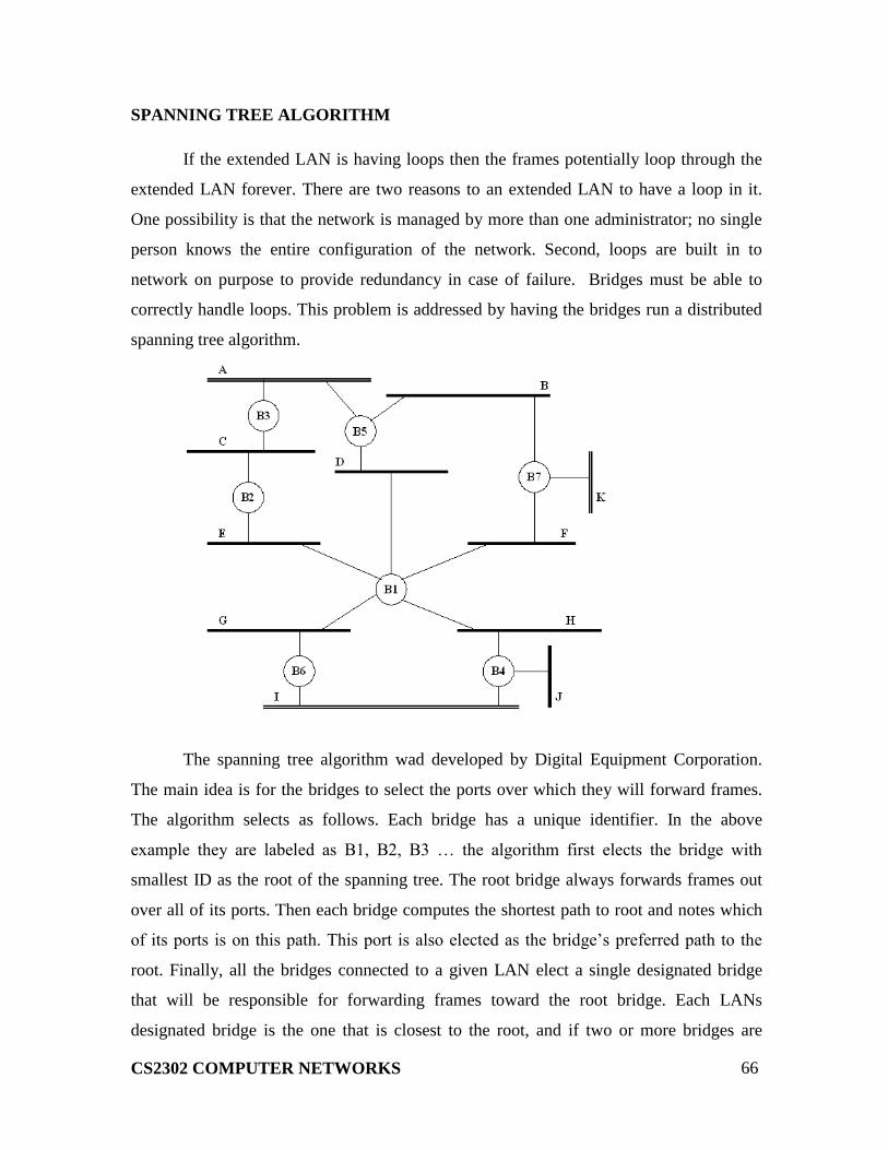
The spanning tree algorithm wad developed by Digital Equipment Corporation.
The main idea is for the bridges to select the ports over which they will forward frames.
The algorithm selects as follows. Each bridge has a unique identifier. In the above
example they are labeled as B1, B2, B3 … the algorithm first elects the bridge with
smallest ID as the root of the spanning tree. The root bridge always forwards frames out
over all of its ports. Then each bridge computes the shortest path to root and notes which
of its ports is on this path. This port is also elected as the bridge‟s preferred path to the
root. Finally, all the bridges connected to a given LAN elect a single designated bridge
that will be responsible for forwarding frames toward the root bridge. Each LANs
designated bridge is the one that is closest to the root, and if two or more bridges are
CS2302 COMPUTER NETWORKS
67
equally close to the root, then the bridge which having smallest ID wins.
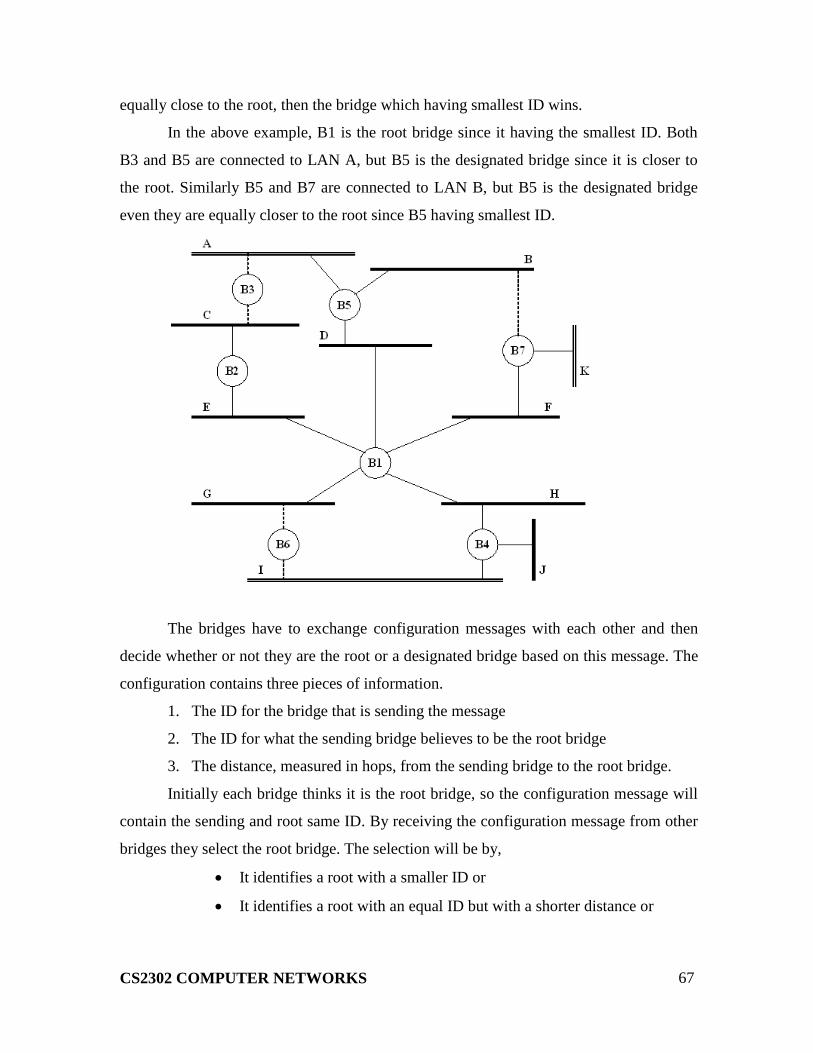
In the above example, B1 is the root bridge since it having the smallest ID. Both
B3 and B5 are connected to LAN A, but B5 is the designated bridge since it is closer to
the root. Similarly B5 and B7 are connected to LAN B, but B5 is the designated bridge
even they are equally closer to the root since B5 having smallest ID.
The bridges have to exchange configuration messages with each other and then
decide whether or not they are the root or a designated bridge based on this message. The
configuration contains three pieces of information.
1. The ID for the bridge that is sending the message
2. The ID for what the sending bridge believes to be the root bridge
3. The distance, measured in hops, from the sending bridge to the root bridge.
Initially each bridge thinks it is the root bridge, so the configuration message will
contain the sending and root same ID. By receiving the configuration message from other
bridges they select the root bridge. The selection will be by,
It identifies a root with a smaller ID or
It identifies a root with an equal ID but with a shorter distance or
CS2302 COMPUTER NETWORKS
68
The root ID and distance are equal, but the sending bridge has a smaller
ID
BROADCAST AND MULTICAST
Most LANs support both broadcast and multicast; then bridges must also support
these two features.
Broadcast is simple, each bridge forward a frame with a destination broadcast
address out on each active port other that the one on which the frame was received. In
multicasting, each host deciding for itself whether or not to accept the message.
CS2302 COMPUTER NETWORKS
69
CS2302 COMPUTER NETWORKS
UNIT III 9
Circuit switching vs. packet switching / Packet switched networks – IP – ARP – RARP –
DHCP – ICMP – Queueing discipline – Routing algorithms – RIP – OSPF – Subnetting
– CIDR – Interdomain routing – BGP – Ipv6 – Multicasting – Congestion avoidance in
network layer
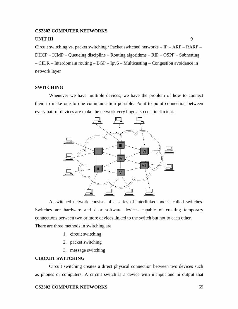
SWITCHING
Whenever we have multiple devices, we have the problem of how to connect
them to make one to one communication possible. Point to point connection between
every pair of devices are make the network very huge also cost inefficient.
A switched network consists of a series of interlinked nodes, called switches.
Switches are hardware and / or software devices capable of creating temporary
connections between two or more devices linked to the switch but not to each other.
There are three methods in switching are,
1. circuit switching
2. packet switching
3. message switching
CIRCUIT SWITCHING
Circuit switching creates a direct physical connection between two devices such
as phones or computers. A circuit switch is a device with n input and m output that

CS2302 COMPUTER NETWORKS
70
creates a temporary connection between an input link and an output link. The number of
inputs does not have to match the number of outputs. An n by n folded switch can
connect n lines in full duplex mode.
Circuit switching today can use either of two technologies:
1. space division switches
2. time division switches
SPACE DIVISION SWITCHES
In space division switches, the paths in the circuit are separated from each other
spatially. It is very useful in analog networks.
Crossbar switches:
A crossbar switch connects n inputs to m outputs in a grid, using electronic micro
switches at each cross point. The major limitation is number of cross points required. To
connect n inputs to m outputs it needs n * m cross points.
Multistage switches:
It combines crossbar switches in several stages. The design of multistage switches
are depends on the number of stages and the number of switches required in each stage.
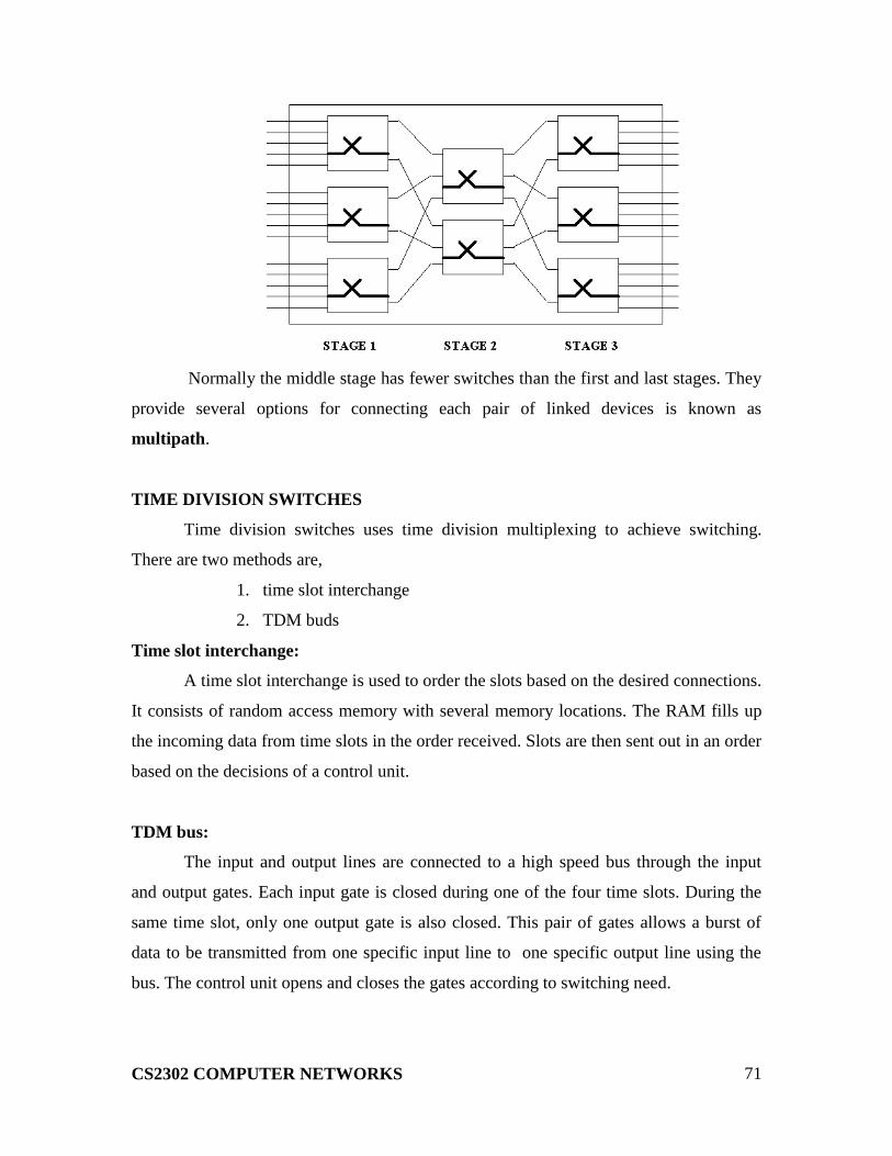
CS2302 COMPUTER NETWORKS
71
Normally the middle stage has fewer switches than the first and last stages. They
provide several options for connecting each pair of linked devices is known as
multipath.
TIME DIVISION SWITCHES
Time division switches uses time division multiplexing to achieve switching.
There are two methods are,
1. time slot interchange
2. TDM buds
Time slot interchange:
A time slot interchange is used to order the slots based on the desired connections.
It consists of random access memory with several memory locations. The RAM fills up
the incoming data from time slots in the order received. Slots are then sent out in an order
based on the decisions of a control unit.
TDM bus:
The input and output lines are connected to a high speed bus through the input
and output gates. Each input gate is closed during one of the four time slots. During the
same time slot, only one output gate is also closed. This pair of gates allows a burst of
data to be transmitted from one specific input line to one specific output line using the
bus. The control unit opens and closes the gates according to switching need.

CS2302 COMPUTER NETWORKS
72
PUBLIC SWITCHED TELEPHONE NETWORK:
An example of a circuit switched network is the public switched telephone
network. The switching centers are organized as five classes are,
Regional office
Sectional office
Primary office
Toll office
End office
DISADVANTAGES:
1. Circuit switching is less suited to data and other non voice communications.
2. less data rate
3. inflexible
4. No priorities allowed.
PACKET SWITCHING
In packet switched network, data are transmitted in discrete units of potentially
variable length blocks called packets. The maximum length of the packet is established

CS2302 COMPUTER NETWORKS
73
by the network. Longer transmission is broken up in to multiple packets.
There are two popular methods are,
1. datagram approach
2. virtual circuit approach
DATAGRAM APPROACH:
In the datagram approach to packet switching, each packet is treated
independently from all there. Even when one packet represents just a piece of a
multipacket transmission, the networks treats it as though it existed alone. Packets in this
technology are referred to datagram.
The datagram approach can be used to deliver four packets from station A to
station X. In this example, all four packets belong to same message but may go by
different paths to reach their destination.
This approach can cause the datagram of a transmission to arrive at their
destination out of order .It is responsibility of transport layer in most protocols to reorder
the data grams before passing them on to the destination port.
The link joining each pair of nodes can contain multiple channels. Each of these
channels is capable, in turn, of carrying data grams either from several different sources
or from one source. Multiplexing can be done using TDM or FDM.
Devices A and B are sending data grams to devices X and Y. Some paths use one
channel while other uses more than one. As you can see, the bottom link is carrying two

CS2302 COMPUTER NETWORKS
74
packets from different sources in the same direction. The link on the right, however, is
carrying data grams in two directions.
VIRTUAL CIRCIUT APPROACH:
In the virtual circuit approach to packet switching, the relationship
between all packets belonging to a message or session is preserved. A single route is
chosen between sender and receiver at the beginning of the session. When the data are
sent, all packets of the transmission travel one after another along that route.
Today, virtual circuit transmission is implemented in two formats: switched
virtual circuit (SVC) & permanent virtual circuit (PVC).
SVC:
The switched virtual circuit (SVC) format is comparable conceptually to dial-up
lines in circuit switching. In this method, a virtual circuit is created whenever it is needed
and exists only for the duration of the specific exchange.
PVC:
Permanent virtual circuits (PVC) are comparable to leased lines in circuit
switching. In this method, the same virtual circuit is provided between two users on a
continuous basis. The circuit is dedicated to the specific users. No one else can use it &,
because it is always in place, it can be used without connection establishment &
connection termination. Whereas two SVC users may get a different route every time
they request a connection, two PVC users always get the same route.
CIRCUIT SWITCHED CONNECTION VS VIRTUAL CIRCUIT CONNECTION:
Although it seems that a circuit-switched connection & a virtual-circuit
connection are the same, there are differences:
Paths versus route:
A circuit-switched connection creates a path between points. The physical
path is created by setting the switches for the duration of the dial(dial-up line) or the
duration of the lease(lease line).A virtual circuit connection creates a route between two
points. This means each switch creates an entry in its routing table for the duration of the
session (SVC) or duration of the lease (PVC).

CS2302 COMPUTER NETWORKS
75
Whenever, the switch receives a packet belonging to a virtual connection, it checks
the table for the corresponding entry & routes the packet out of one of its interfaces.
Dedicated versus sharing:
In a circuit-switched connection, the links that make a path are dedicated;
they cannot be used by other connections. In a virtual circuit connection, the links that
make a route can be shared by other connections.
MESSAGE SWITCHING:
Message switching is best known by the descriptive term store and forward. In
this mechanism, a node receives a message, stores it until the appropriate route is free,
then sends it along.
Store & forward is considered a switching technique because there is no direct
link between the sender and receiver of a transmission. A message is delivered to the
node along one path then rerouted along another to its destination.
Note that in message switching, the messages are stored & relayed from
secondary storage (disk), while in packet switching the packets are stored and forwarded
from primary storage (RAM).
Message switching was common in the 1960s & 1970s.The primary use has been
to provide high-level network services for unintelligent devices. Since such devices have
been replaced, this type of switch has virtually disappeared. Also, the delays inherent in
the process, as well as requirements for large-capacity storage media at each node, make
it popular for direct communication.
INTERNETWORK:
An internetwork is often referred to as a network of networks because it is
made up of lots of smaller networks. The nodes that interconnect the networks are called
routers. They are also sometimes called gateways, but since this term has several other
connotations, we restrict our usage to router. The internet protocol is the key tool used
today to build scalable, heterogeneous internetwork.

CS2302 COMPUTER NETWORKS
76
SERVICE MODEL:
The main concern in defining a service model for an internetwork is that we can
provide a host-to-host service only if this service can somehow be provided over each of
the underlying physical networks. For Example, it would be no good deciding that our
internetwork service model was going to provide guaranteed delivery of every packet in
1 ms or less if there were underlying network technologies that could arbitrarily delay
packets.
The IP service model can be thought of as having two parts: an addressing
scheme, which provides a way to identify all hosts in the internetwork, and a datagram
(connectionless) model of data delivery. This service model is sometimes called best
effort because, although IP makes every effort to delivery datagram, it makes no
guarantees.
DATAGRAM DELIVERY:
A datagram is a type of packet that happens to be sent in a connectionless manner
over a network. Every datagram carries enough information to let network forward the
packet to its correct destination; there is no need for any advance setup mechanism to tell
the network what to do when the packet arrives. The network makes its best effort to get
it to the desired destination. The best-effort part means that if something goes wrong and

CS2302 COMPUTER NETWORKS
77
the packet gets lost, corrupted, misdelivered,or in any way fails to reach its intended
destination, the network does nothing-it made its best effort, and that is all it had to do. It
does not make any attempt to recover from the failure. This is sometimes called an
unreliable service.
PACKET FORMAT:
The IP datagram, like most packets, consists of a header followed by a
number of bytes of data.
The Version field specifies the version of IP. The current version of IP is 4, and it
is sometimes called IPv4^2.putting this field right at the start of the datagram makes it
easy for everything else in the packet format to be redefined in subsequent versions; the
header processing software starts off by looking at the version and then branches off to
process the rest of the packet according to the appropriate format.
The next field, HLEN, specifies the length of the header in 32-bit words. When
there are no options, which is most of the time, the header is 5 words (20 bytes) long. The
8_bit type of service (TOS) field has had a number of different definitions over the years,
but its basic function is to allow packets to be treated differently based on application
needs. For example, the TOS value might determine whether or not a packet should be
placed in a special queue that receives low delay.
The next 16-bit of the header contain the Length of the datagram, including

CS2302 COMPUTER NETWORKS
78
the header. Unlike the HLEN field, the Length field counts bytes rather than words. Thus,
the maximum size of an IP datagram is 65,535 bytes. The physical network, over which
IP is running, however, may not support such long packets. For this reason, IP supports a
fragmentation and reassembly process, the second word of the header contains
information about fragmentation. The next byte is the time to live (TTL) field. The intent
of the field is to catch packets that have been going around in routing loops and discard
them, rather than let them consume resources indefinitely.
The Protocol field is simply a demultiplexing key that identifies the higher-
level protocol to which this packet should be passed. These are values defined for TCP
(6), UDP (17), and many other protocols that may sit above IP in the protocol graph.
The Checksum is calculated by considering the entire IP header as a sequence
of 16-bit words, adding them up using ones complement arithmetic, and taking the ones
complement of the result.
The last two required fields in the header are the SourceAddr and the
DestinationAddr for the packet. The latter is the key to datagram delivery: every packet
contains a full address for its intended destination so that forwarding decisions can be
made at each router. The source address is required tom allow recipients to decide if they
want to accept the packet and to enable them to reply.
Finally, there may be a number of options at the end of the header. The
presence or absence of options may be determined by examining the header length
(HLen) field. While options are used fairly rarely, a complete IP implementation must
handle them all.
FRAGMENTATION AND REASSEMBLY:
One of the problems of providing a uniform host-to-host service
model over a heterogeneous collection of network is that each network technology tends
to have its own idea of how large a packet can be. For example, an Ethernet can accept
packets up to 1,500 bytes long, while FDDI packets may be 4,500 bytes long.
This leaves two choices for the IP service model: make sure that all IP
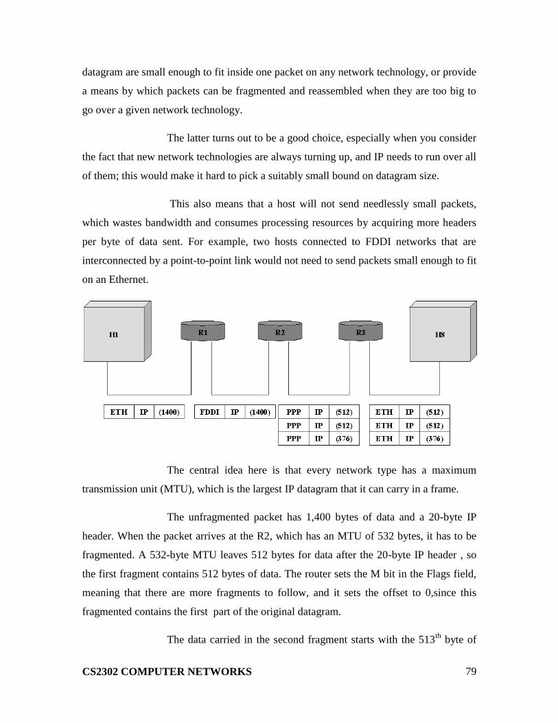
CS2302 COMPUTER NETWORKS
79
datagram are small enough to fit inside one packet on any network technology, or provide
a means by which packets can be fragmented and reassembled when they are too big to
go over a given network technology.
The latter turns out to be a good choice, especially when you consider
the fact that new network technologies are always turning up, and IP needs to run over all
of them; this would make it hard to pick a suitably small bound on datagram size.
This also means that a host will not send needlessly small packets,
which wastes bandwidth and consumes processing resources by acquiring more headers
per byte of data sent. For example, two hosts connected to FDDI networks that are
interconnected by a point-to-point link would not need to send packets small enough to fit
on an Ethernet.
The central idea here is that every network type has a maximum
transmission unit (MTU), which is the largest IP datagram that it can carry in a frame.
The unfragmented packet has 1,400 bytes of data and a 20-byte IP
header. When the packet arrives at the R2, which has an MTU of 532 bytes, it has to be
fragmented. A 532-byte MTU leaves 512 bytes for data after the 20-byte IP header , so
the first fragment contains 512 bytes of data. The router sets the M bit in the Flags field,
meaning that there are more fragments to follow, and it sets the offset to 0,since this
fragmented contains the first part of the original datagram.
The data carried in the second fragment starts with the 513th
byte of

CS2302 COMPUTER NETWORKS
80
the original data, so the Offset field in this header is set to 64,which is 512/8. Why the
division by 8? Because the designers of IP decided that fragmentation should always
happen on 8-byte boundaries, which means that the Offset field counts 8-byte chunks, not
bytes. The third fragment contains the last 376 bytes of data, and the offset is now
2*512/8=128.since this is the last fragment, the M bit is not set.
GLOBAL ADRESSES:
Global uniqueness is the first property that should be provided in an
addressing scheme. Ethernet addresses are globally unique but not sufficient to address
entire network. And also they are flat that is no structure in addressing.
IP addresses are hierarchical. They made up of two parts, they are a

CS2302 COMPUTER NETWORKS
81
network part and a host part. The network part identifies the network to which the host is
connected. All hosts which are connected to the same network have same network part in
their IP address. The host part then identifies each host on the particular network.
The routers are host but they are connected with two networks. So
they need to have an address on each network, one for each interface.
IP addresses are divided into three different classes. They are,
1. class A
2. class B
3. class C
The class of an IP address is identified in the most significant few
bits. If the first bit is 0, it is a class A address. If the first bit is 1 and the second bit is 0, it
is a class B address. If the first two bits are 1 and the third bit is 0, t is a class C address.
Class A addresses have 7 bits for network part and 24 bits for host
part. So 126 class A networks each can accommodate 224
-2 (about 16 million) hosts. The
0 and 127 are reserved.
Class B addresses have 14 bits for network part and 16 bits for host

CS2302 COMPUTER NETWORKS
82
part. So 214
-2 class B networks each can accommodate 216
-2 (about 65,534) hosts.
Class C addresses have 21 bits for network part and 8 bits for host
part. So 221
-2 class C networks each can accommodate 28-2 (about 254) hosts. The 0 and
127 are reserved.
There are approximately 4 billion possible IP addresses, one half
for class A, one quarter for class B and one-eighth for class C address. There are also
class D and class E are there. But class D for multicast and class E are currently unused.
IP addresses are written as four decimal integers separated vy dots.
Each integer represents the decimal value contained in 1 byte of the address, starting at
the most significant.
DATAGRAM FORWARDING IN IP
A datagram is sent from a source to a destination, possibly passing
through several routers along the way. Any node, whether it is a host or a router, first
tries to establish whether it is connected to the same network as the destination. It
compares the network part of the destination address with its network part. If match
occurs, then it directly deliver the packet over the network. Else, then it sends to a router.
Among several routers, the nearest one will be selected. If none of the entries in the table
match the destination‟s network number it forwards to the default router.
Datagram forwarding algorithm is,
If (networknum of destination = networknum of one of my interface) then
Deliver packet to destination over that interface
Else
If (networknum of destination is in my forwarding table) then
Deliver packet to nexthop router
Else
Deliver packet to default router
For a host with only one interface and one default router in its
forwarding table, this simplifies to

CS2302 COMPUTER NETWORKS
83
If (networknum of destination = my networknum ) then
Deliver packet to destination directly
Else
Deliver packet to default router
EXAMPLE
NetworkNum NextHop
1 R3
2 R1
NetworkNum NextHop
1 R3
2 R1
3 Interface 1
4 Interface 0
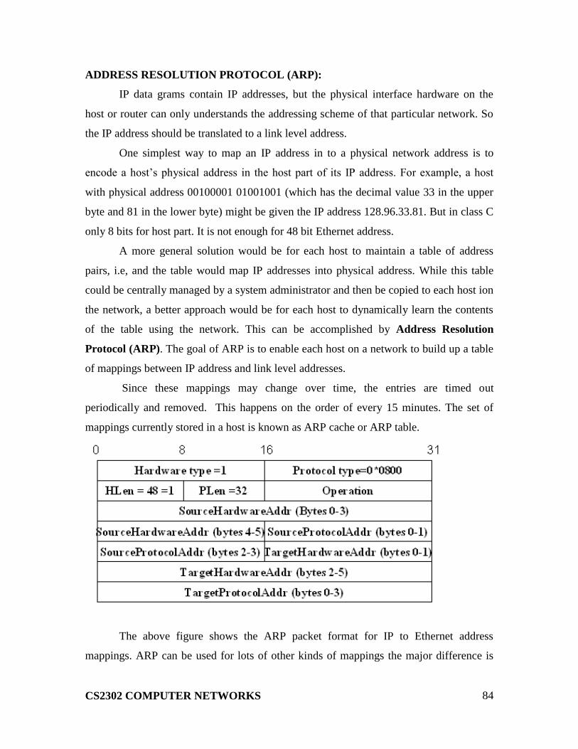
CS2302 COMPUTER NETWORKS
84
ADDRESS RESOLUTION PROTOCOL (ARP):
IP data grams contain IP addresses, but the physical interface hardware on the
host or router can only understands the addressing scheme of that particular network. So
the IP address should be translated to a link level address.
One simplest way to map an IP address in to a physical network address is to
encode a host‟s physical address in the host part of its IP address. For example, a host
with physical address 00100001 01001001 (which has the decimal value 33 in the upper
byte and 81 in the lower byte) might be given the IP address 128.96.33.81. But in class C
only 8 bits for host part. It is not enough for 48 bit Ethernet address.
A more general solution would be for each host to maintain a table of address
pairs, i.e, and the table would map IP addresses into physical address. While this table
could be centrally managed by a system administrator and then be copied to each host ion
the network, a better approach would be for each host to dynamically learn the contents
of the table using the network. This can be accomplished by Address Resolution
Protocol (ARP). The goal of ARP is to enable each host on a network to build up a table
of mappings between IP address and link level addresses.
Since these mappings may change over time, the entries are timed out
periodically and removed. This happens on the order of every 15 minutes. The set of
mappings currently stored in a host is known as ARP cache or ARP table.
The above figure shows the ARP packet format for IP to Ethernet address
mappings. ARP can be used for lots of other kinds of mappings the major difference is

CS2302 COMPUTER NETWORKS
85
their address size. In addition to the IP and link level addresses of both sender and target,
the packet contains
o a HardwareType fiels, which specifies the type of the physical network (ex.,
Ethernet)
o a ProtocolType field, which specifies the higher layer protocol (ex., IP)
o HLen (hardware address length) and PLen (protocol address length) fields, which
specifies the length of the link layer address and higher layer protocol address,
respectively
o An Operation field, which specifies whether this is a request or a response
o The source and target hardware (Ethernet) and protocol (IP) address.
The results of the ARP process can be added as an extra column in a forwarding
table.
HOST CONFIGURATION (DHCP)
Ethernet addresses are configured into the network adaptor by the manufacturer,
and this process is managed in such a way that these addresses are globally unique. This
is clearly a sufficient condition to ensure that any collection of hosts connected to a single
Ethernet will have unique addresses. IP addresses by contrast must be not only unique on
a given internetwork, but also must reflect the structure of the internetwork. They contain
a network part and a host part; the network part must be the same for all hosts on the
same network.
Thus, it is not possible for the IP addresses to be configured once into a host
when it is manufactured, since that would imply that the manufacturer knew which hosts
were going to end up on which networks, and it would mean that a host, once connected
to one network, could never move to another. For this reason, IP addresses need to be
reconfigurable.
There are some obvious drawbacks in manual configuration by system
administrator. So automated configuration methods are required. The primary method
uses a protocol known as Dynamic Host Configuration Protocol (DHCP).
DHCP relies on the existence of a DHCP server that is responsible for providing
configuration information to hosts. At the simplest level, the DHCP server can function

CS2302 COMPUTER NETWORKS
86
just as a centralized repository for host configuration information. The configuration
information for each host could be stored in the DHCP server and automatically retrieved
by each host when it is booted or connected to the network. The configuration
information for each host stored in a table that is indexed by some form of unique client
identifier, typically hardware address.
To contact a DHCP server the host sends a DHCPDISCOVER message to a
special IP address (255.255.255.255) that is an IP broadcast address. It will received by
all host and routers on the network. DHCP uses the concept of a relay agent. There is at
least one relay agent on each network, and it is configured with just one piece of
information, the IP address of DHCP server. When a relay agent receives a
DHCPDISCOVER message, it unicasts it to the DHCP server and awaits the response,
which it will send back to the requesting client

CS2302 COMPUTER NETWORKS
87
The packet format is shown above. The message is sent using a protocol called
the User Datagram Protocol (UDP). When trying to obtain the configuration information,
the client puts its hardware address in the chaddr field. The DHCP server replies by
filling in the yiaddr (your IP address) field and sending to the client.
ERROR REPORTING (ICMP)
While IP is perfectly willing to drop data grams when the going gets tough for
example. When a router does not know how to forward the data gram or when one
fragment of a datagram fails to arrive at the destination it does not necessarily fail
silently. IP is always configured with a companion protocol, known as Internet Control
Message Protocol (ICMP) that defines a collection of error messages that are sent back to
the source host whenever a router or host is unable to process an IP data gram
successfully. For example, ICMP defines error message indicating that the destination
host is unreachable, that the reassembly process failed, that the TTL had reached 0, that
the IP header checksum failed and so on. ICMP defines a handful of control message that
a router can send back to a source host. Ex., ICMP-redirect tells the source host that there
is better route to the destination

CS2302 COMPUTER NETWORKS
88
CS2302 COMPUTER NETWORKS
UNIT IV 9
UDP – TCP – Adaptive Flow Control – Adaptive Retransmission - Congestion control –
Congestion avoidance – QoS
UDP - SIMPLE DEMULTIPLEXER (UDP)
The simplest transport protocol is one that extends the host-to-host delivery
service of the underlying network into a process-to-process communication service.
There are likely to be many processes running on any given host, so the protocol needs to
add a level of demultiplexing, thereby allowing multiple application process on each host
to share the network. Aside from this requirement, the transport protocol adds no other
functionality to the best-effort service provided by the underlying network. The Internet‟s
Users Datagram protocol (UDP) is an example of such a transport protocol.
The only interesting issue in such a protocol is the form of the address used to
identify the target process. Although it is possible for a process to directly identify each
other with an OS-assigned process ID (pid), such an approach is only practical in a closed
distributed system. in which a single OS runs on all hosts and assigns each process a
unique ID.A more common approach, and the one used by UDP, is for process to
indirectly identify each other using an abstract locater, often called a port or mail box.
The basic idea is for a source process to send a message to a port and for the destination
process to receive the message from a port.

CS2302 COMPUTER NETWORKS
89
The header for an end-to-end protocol that implements this demultiplexing
function typically contains an identifier (port) for both the sender (source)and the
receiver(destination)of the message. The UDP port field is only 16bits long. This means
that there are up to 64K possible ports, clearly not enough to identify all the processes on
all the hosts in the Internet. Fortunately, ports are not interpreted across the entire
Internet, but only on a single host. That is, a process is really identified by a port on some
particular host-<port, host >pair. In fact, this pair constitutes the demultiplexing key for
the UDP protocol.
The next issue is how a process learns the port for the process to which it wants to
send the message. Typically a client process initiates a message exchange with a server
process. Once a client has contacted a server, the server knows the client‟s port (it was
contained in the message header) and can reply to it. The real problem, therefore, is how
the client learns the server‟s port in the first place. A common approach is for the server
to accept messages at a well known port. That is, each server receives its messages at
some fixed port that is widely published, much like the emergency telephone service
available at the well-known number 911.In the Internet, for example, the domain name
server (DNS) receives messages at well-known port 53 on each host, the mail service
listens of messages at port 25,and the Unix talk program accepts messages at well known
port 517,and so on. This mapping is published periodically in an RFC and is available on
the most Unix systems in file /etc/services. Sometimes a well-known port to agree on
some other port that they will use for subsequent communication leaving the well-known
port free for other clients.
An alternative strategy is to generalize this idea, so that there is only a single well-
known port- the one at which the “port mapper” service accepts messages. A client would
send a message to the port mapper‟s well known port asking for the port it should use to
talk to the “whatever” service and the port associated with different services over time,
and for each host to use a different port for the same service.

CS2302 COMPUTER NETWORKS
90
As just mentioned, a port is purely an abstraction. Exactly how it is implemented
differs from system to system, or more precisely, from OS to OS. For example, the socket
API is an example implementation of ports. Typically, a port is implemented by a
message queue. When a message arrives, the protocol l(eg.UDP) appends the message to
the end of the queue. Should the queue be full, the message is discarded. There is no
flow-control mechanism that tells the sender to slow down. When an application process
wants to receive a message, one is removed from the front of the queue. If the queue is
empty, the process blocks until a message becomes available.
Finally, although UDP does not implement flow control or reliable/ordered
delivery, it does a little more work than to simplify demultiplexer messages to some
application process- it also ensures the correctness of the message by the use of a
checksum.(The UDP checksum is optional in the current Internet, but it will become
mandatory with IPv6.) UDP computes its checksum over the UDP header, the contents of
the message body, and something called the pseudo header. The pseudo header consists
of three fields from IP header- protocol number , source IP address and destination IP
address- plus the UDP length field.(Yes, the UDP length field is included twice in the
checksum calculation.) UDP uses the same checksum algorithm as IP, as defined. The

CS2302 COMPUTER NETWORKS
91
motivation behind having the pseudo header is to verify that this message has been
delivered between the correct two endpoints For example, if the destination IP address
was modified while the packet was in transit, causing the packet to be misdelivered, or,
this fact would be detected by the UDP checksum.
TCP - RELIABLE BYTE STREAM:
TCP is a more sophisticated transport protocol is one that offers a reliable,
connection oriented byte stream service. Such a service has proven useful to a wide
assortment of application because it frees the application from having to worry about
missing or reordered data.
TCP guarantees the reliable in order delivery of a stream of bytes. It is a full
duplex protocol meaning that each TCP connection supports a pair of byte streams, one
flowing each direction. It also includes a flow control mechanism for each of these byte
streams that allow the receiver to limit how much data the sender can transmit at a given
time.
Finally, like UDP, TCP supports a demultiplexing mechanism that allows
multiple application programs on any given host to simultaneously carry on a
conversation with their peers. In addition to the above features, TCP also implements a
highly tuned congestion control mechanism.
END TO END ISSUES:
At the heart of TCP is sliding window algorithm. TCP supports logical
connections between processes that are running on any two computers in the internet.
This means that TCP needs an explicit connection establishment phase during which the
two sides of the connection agree to exchange data with each other. This difference is
analogous to having a dedicated phone line. TCP also has an explicit connection
teardown phase.
One of the things that happen during connection establishment is that the two
parties establish some shared state to enable the sliding window algorithm to begin.
Connection teardown is needed so each host known it is OK to free this state.

CS2302 COMPUTER NETWORKS
92
Whereas, a single physical link that always connects the same two computers
has a fixed RTT, TCP connection are likely to have widely different round trip times.
Variations in the RTT are even possible during a single TCP connection.
Packets may be reordered as they cross the internet, but this is not possible on a point-to-
point link where the first packet put into one end of the link must be the first to appear at
the other end. Packets that are slightly out of order don‟t cause a problem since the
sliding window algorithm can reorder packets correctly using the sequence number.
TCP assumes that each packet has a maximum lifetime. The exact lifetime,
known as the maximum segment lifetime (MSL), is an engineering choice. The current
recommended setting is 120seconds.
The computers connected to a point to point link are generally engineered to
support the link. For example, if a link‟s delay X bandwidth product is computed to be
8KB –meaning that a window size is selected to allow up to 8kb of data to be
unacknowledgement at a given time then it is likely that the computers at either end of
the link have the ability to buffer up to 8kb of data.
Because the transmitting side of a directly connected link cannot send any
faster than the bandwidth of the link allows, and only one host is pumping data into the
link, it is not possible to unknowingly congest the link. Said another way, the load on the
link is visible in the form of a queue of packets at the sender. In contrast, the sending side
of a TCP connection has no idea what links will be traversed to reach the destination.
SEGMENT FORMAT:

CS2302 COMPUTER NETWORKS
93
TCP is a byte oriented protocol, which means that the sender writes bytes
into a TCP connection and the receiver reads bytes out of the TCP connection. Although
“byte stream” describes the service TCP offers to application processes, TCP does not
itself transmit individual bytes over the internet. Instead, TCP on the source host buffers
enough bytes from the sending process to fill a reasonably sized packet and then sends
this packet to its peer on the destination host. TCP on the destination host then empties
the contents of the packet into a receiving process reads from this buffer at its leisure.
The packets exchanged between TCP peers are called segments, since each one
carries a segment of the byte stream. The SrcPort and Distorts fields identify the source
and destination ports, respectively, just as in UDP. These two fields, plus the source and
destination IP addresses, combine to uniquely identify each TCP connection. That is,
TCP‟s demux key is given by the 4-tuple
(SrcPort, SrclPAddr, DstPort, DstlPAddr)
The acknowledgement, sequence num and advertised window fields are all
involved in TCP‟s sliding window algorithm. Because TCP is a byte oriented protocol,
each byte of data has a sequence number, the sequence num field contains the sequence
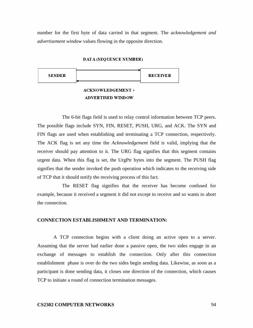
CS2302 COMPUTER NETWORKS
94
number for the first byte of data carried in that segment. The acknowledgement and
advertisement window values flowing in the opposite direction.
The 6-bit flags field is used to relay control information between TCP peers.
The possible flags include SYN, FIN, RESET, PUSH, URG, and ACK. The SYN and
FIN flags are used when establishing and terminating a TCP connection, respectively.
The ACK flag is set any time the Acknowledgement field is valid, implying that the
receiver should pay attention to it. The URG flag signifies that this segment contains
urgent data. When this flag is set, the UrgPtr bytes into the segment. The PUSH flag
signifies that the sender invoked the push operation which indicates to the receiving side
of TCP that it should notify the receiving process of this fact.
The RESET flag signifies that the receiver has become confused for
example, because it received a segment it did not except to receive and so wants to abort
the connection.
CONNECTION ESTABLISHMENT AND TERMINATION:
A TCP connection begins with a client doing an active open to a server.
Assuming that the server had earlier done a passive open, the two sides engage in an
exchange of messages to establish the connection. Only after this connection
establishment phase is over do the two sides begin sending data. Likewise, as soon as a
participant is done sending data, it closes one direction of the connection, which causes
TCP to initiate a round of connection termination messages.
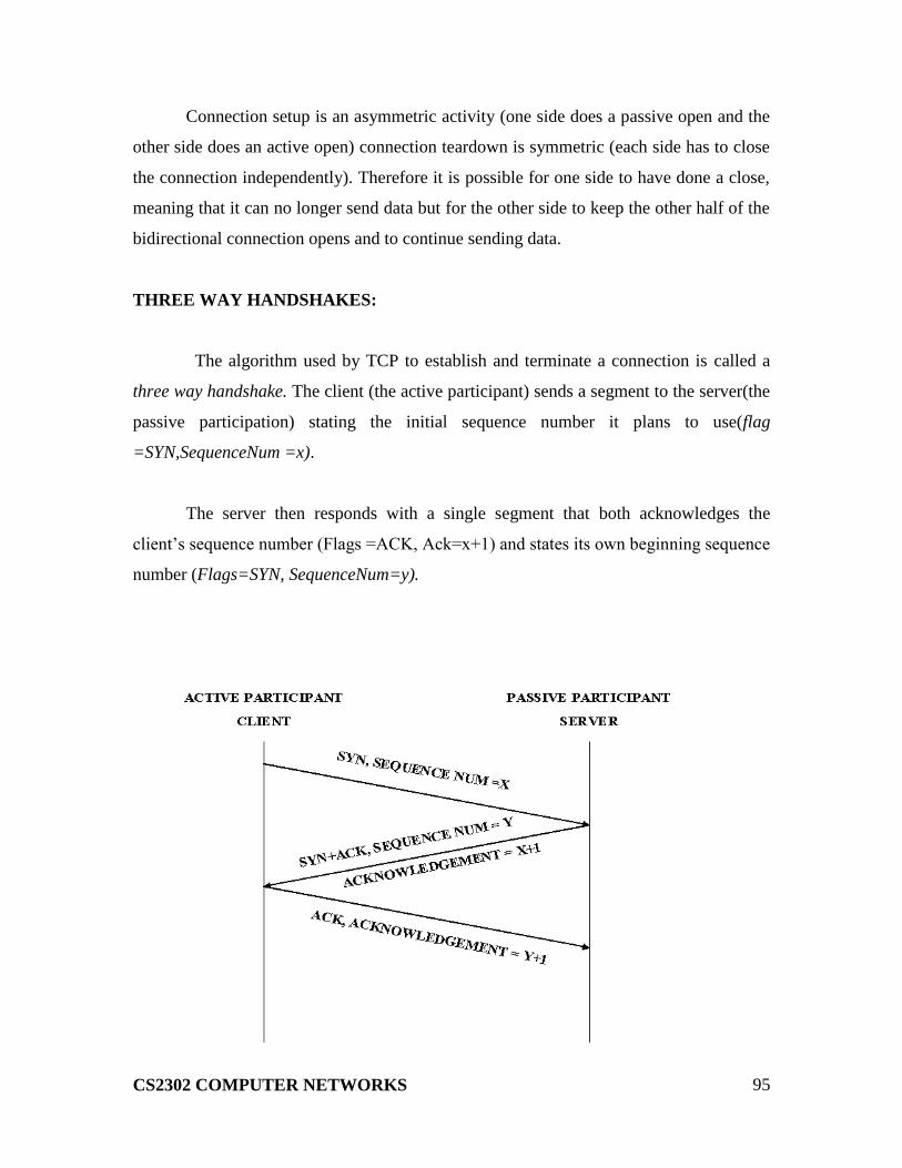
CS2302 COMPUTER NETWORKS
95
Connection setup is an asymmetric activity (one side does a passive open and the
other side does an active open) connection teardown is symmetric (each side has to close
the connection independently). Therefore it is possible for one side to have done a close,
meaning that it can no longer send data but for the other side to keep the other half of the
bidirectional connection opens and to continue sending data.
THREE WAY HANDSHAKES:
The algorithm used by TCP to establish and terminate a connection is called a
three way handshake. The client (the active participant) sends a segment to the server(the
passive participation) stating the initial sequence number it plans to use(flag
=SYN,SequenceNum =x).
The server then responds with a single segment that both acknowledges the
client‟s sequence number (Flags =ACK, Ack=x+1) and states its own beginning sequence
number (Flags=SYN, SequenceNum=y).
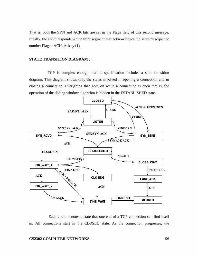
CS2302 COMPUTER NETWORKS
96
That is, both the SYN and ACK bits are set in the Flags field of this second message.
Finally, the client responds with a third segment that acknowledges the server‟s sequence
number Flags =ACK, Ack=y+1).
STATE TRANSITION DIAGRAM :
TCP is complex enough that its specification includes a state transition
diagram. This diagram shows only the states involved in opening a connection and in
closing a connection. Everything that goes on while a connection is open that is, the
operation of the sliding window algorithm is hidden in the ESTABLISHED state.
Each circle denotes a state that one end of a TCP connection can find itself
in. All connections start in the CLOSED state. As the connection progresses, the
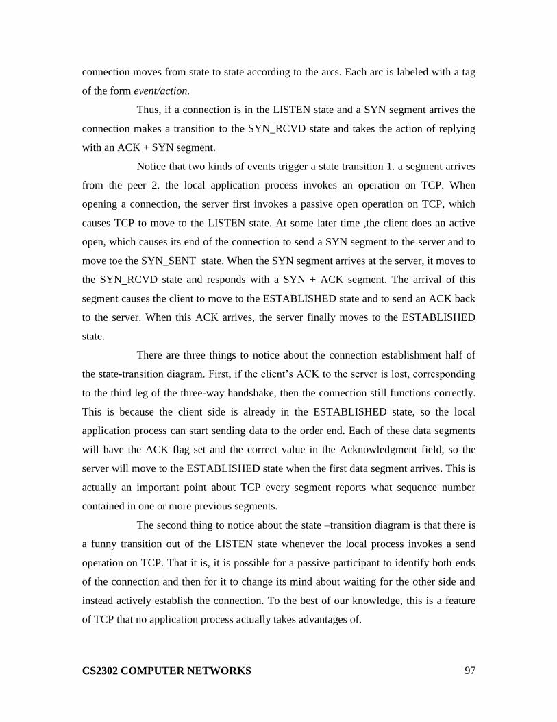
CS2302 COMPUTER NETWORKS
97
connection moves from state to state according to the arcs. Each arc is labeled with a tag
of the form event/action.
Thus, if a connection is in the LISTEN state and a SYN segment arrives the
connection makes a transition to the SYN_RCVD state and takes the action of replying
with an ACK + SYN segment.
Notice that two kinds of events trigger a state transition 1. a segment arrives
from the peer 2. the local application process invokes an operation on TCP. When
opening a connection, the server first invokes a passive open operation on TCP, which
causes TCP to move to the LISTEN state. At some later time ,the client does an active
open, which causes its end of the connection to send a SYN segment to the server and to
move toe the SYN_SENT state. When the SYN segment arrives at the server, it moves to
the SYN_RCVD state and responds with a SYN + ACK segment. The arrival of this
segment causes the client to move to the ESTABLISHED state and to send an ACK back
to the server. When this ACK arrives, the server finally moves to the ESTABLISHED
state.
There are three things to notice about the connection establishment half of
the state-transition diagram. First, if the client‟s ACK to the server is lost, corresponding
to the third leg of the three-way handshake, then the connection still functions correctly.
This is because the client side is already in the ESTABLISHED state, so the local
application process can start sending data to the order end. Each of these data segments
will have the ACK flag set and the correct value in the Acknowledgment field, so the
server will move to the ESTABLISHED state when the first data segment arrives. This is
actually an important point about TCP every segment reports what sequence number
contained in one or more previous segments.
The second thing to notice about the state –transition diagram is that there is
a funny transition out of the LISTEN state whenever the local process invokes a send
operation on TCP. That it is, it is possible for a passive participant to identify both ends
of the connection and then for it to change its mind about waiting for the other side and
instead actively establish the connection. To the best of our knowledge, this is a feature
of TCP that no application process actually takes advantages of.
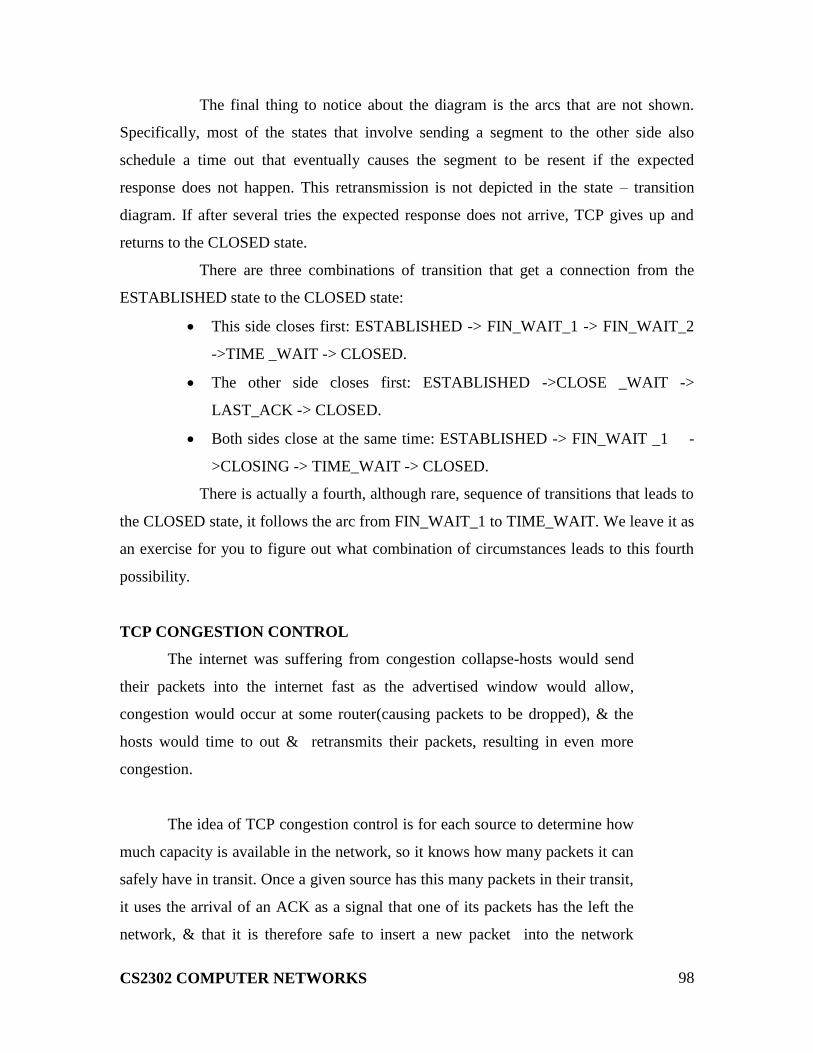
CS2302 COMPUTER NETWORKS
98
The final thing to notice about the diagram is the arcs that are not shown.
Specifically, most of the states that involve sending a segment to the other side also
schedule a time out that eventually causes the segment to be resent if the expected
response does not happen. This retransmission is not depicted in the state – transition
diagram. If after several tries the expected response does not arrive, TCP gives up and
returns to the CLOSED state.
There are three combinations of transition that get a connection from the
ESTABLISHED state to the CLOSED state:
This side closes first: ESTABLISHED -> FIN_WAIT_1 -> FIN_WAIT_2
->TIME _WAIT -> CLOSED.
The other side closes first: ESTABLISHED ->CLOSE _WAIT ->
LAST_ACK -> CLOSED.
Both sides close at the same time: ESTABLISHED -> FIN_WAIT _1 -
>CLOSING -> TIME_WAIT -> CLOSED.
There is actually a fourth, although rare, sequence of transitions that leads to
the CLOSED state, it follows the arc from FIN_WAIT_1 to TIME_WAIT. We leave it as
an exercise for you to figure out what combination of circumstances leads to this fourth
possibility.
TCP CONGESTION CONTROL
The internet was suffering from congestion collapse-hosts would send
their packets into the internet fast as the advertised window would allow,
congestion would occur at some router(causing packets to be dropped), & the
hosts would time to out & retransmits their packets, resulting in even more
congestion.
The idea of TCP congestion control is for each source to determine how
much capacity is available in the network, so it knows how many packets it can
safely have in transit. Once a given source has this many packets in their transit,
it uses the arrival of an ACK as a signal that one of its packets has the left the
network, & that it is therefore safe to insert a new packet into the network

CS2302 COMPUTER NETWORKS
99
without adding to the level of congestion. By using ACKs to pace the
transmission of packets, TCP is said to self-clocking.
ADDITIVE INCREASE/MULTIPLICATIVE DECREASE:
TCP maintains a new state variable for each connection, called
Congestion Window, which is used by the source to limit how much data it is
allowed to have in transit at a given time .The congestion window is congestion
control‟s counterpart to flow control‟s advertised window. TCP is modified
such that the maximum number of bytes of unacknowledged data allowed is
now the minimum of the congestion window and the advertised window .TCP‟s
effective window is revised as follows:
Max Window =MIN (Congestion Window, Advertised Window)
Effective Window =Max Window – (Last Byte Sent- Last Byte
Acked)
The problem, of course, is TCP comes to learn an appropriate value for
Congestion Window . Unlike the Advertised Window, which is sent by the
receiving side of the connection, there is no one to send a suitable Congestion
Window based on the level of congestion it perceives to exist in the network.
This involves decreasing the congestion goes up & increasing the congestion
window when the level of congestion goes down. Taken together, the
mechanism is commonly called additive increase/multiplicative decrease
(AIMD);

CS2302 COMPUTER NETWORKS
100
SLOWSTART:
The additive increase mechanism just described is the right approach to
use when the source is operating close to the available capacity of the network,
but it takes too long to ramp up a connection when it is starting from scratch.
TCP therefore provides the second mechanism, ironically called slow chat that
is used to increase the congestion window rapidly from the cold start. Slow start
effectively increases the congestion window exponentially, rather than linearly.
The source starts out by setting Congestion Window to one packet.
When the ACK for this packet arrives, TCP adds 1 to Congestion Window and
then sends two packets. Upon their receiving the corresponding two ACKs,
TCP increments the Congestion Window by 2-one for each ACK –and next
sends four packets. The end result is that TCP effectively doubles the number of
packets it has in transit every RTT.
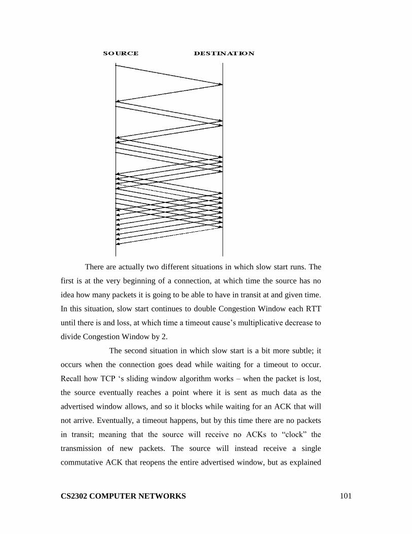
CS2302 COMPUTER NETWORKS
101
There are actually two different situations in which slow start runs. The
first is at the very beginning of a connection, at which time the source has no
idea how many packets it is going to be able to have in transit at and given time.
In this situation, slow start continues to double Congestion Window each RTT
until there is and loss, at which time a timeout cause‟s multiplicative decrease to
divide Congestion Window by 2.
The second situation in which slow start is a bit more subtle; it
occurs when the connection goes dead while waiting for a timeout to occur.
Recall how TCP „s sliding window algorithm works – when the packet is lost,
the source eventually reaches a point where it is sent as much data as the
advertised window allows, and so it blocks while waiting for an ACK that will
not arrive. Eventually, a timeout happens, but by this time there are no packets
in transit; meaning that the source will receive no ACKs to “clock” the
transmission of new packets. The source will instead receive a single
commutative ACK that reopens the entire advertised window, but as explained

CS2302 COMPUTER NETWORKS
102
above, the source then uses slow start to restart the flow of data rather than
dumping a whole window‟s worth of data on the network all at once.
FAST RETRANSMIT AND FAST RECOVERY:
The idea of fast retransmit is straight forward. Every time a data packet
arrives at the receiving side, the receiver responds with an acknowledgement,
even if this sequence number has already been acknowledged. Thus, when a
packet arrives out of order – that is, TCP cannot yet acknowledge the data the
packet contains because earlier data has not yet arrived – TCP resends the same
acknowledgement it sent the last time. This second transmission of the
acknowledgement is called a duplicate ACK .When the sending side sees a
duplicate ACK , it knows that the other side must have received a packet out of
order, which suggests that an earlier packet has might have been lost. Since it is
also possible that the earlier packet has only been delayed rather than lost , the
sender waits until it sees some number of duplicate ACKs and then retransmits
the missing packet. In practice, TCP waits until it has seen three duplicate
ACKs before retransmitting the packet.
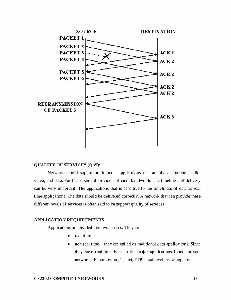
CS2302 COMPUTER NETWORKS
103
QUALITY OF SERVICES (QoS):
Network should support multimedia applications that are those combine audio,
video, and data. For that it should provide sufficient bandwidth. The timeliness of delivery
can be very important. The applications that is sensitive to the timeliness of data as real
time applications. The data should be delivered correctly. A network that can provide these
different levels of services is often said to be support quality of services.
APPLICATION REQUIREMENTS:
Applications are divided into two classes. They are
real time
non real time – they are called as traditional data applications. Since
they have traditionally been the major applications found on data
networks. Examples are, Telnet, FTP, email, web browsing etc.

CS2302 COMPUTER NETWORKS
104
TAXONOMY OF REAL TIME APPLICATIONS:
The characteristics used to categorize the applications are,
1. tolerance of loss of data
2. adaptability
APPROACHES TO QoS SUPPORT:
The approaches are divided into two broad categories. They are,
1. Fine-grained approaches, which provide QoS to individual applications
of flows.
2. Coarse-grained approaches, which provides QoS to large class of data or
aggregated traffic.
In the first category, integrated services are used and in the second category
differentiated services are used.
INTEGRATED SERVICES (RSVP)
The term “Integrated Services” refers to a body of work that was produced by the
IETF around 1995-97.The IntServ working group developed the specifications of a
number of service classes designed to meet the needs of some of the application types
described above. It also defined how RSVP could be used to make reservations using these
service classes.
SERVICE CLASSES:
One of the service classes is designed for intolerant applications. These
applications require that a packet never arrive late. The network should guarantee that the
maximum delay that any packet will experience has some specified value; the application
can then set its playback point so that no packet will ever arrive after its playback time.
The aim of the controlled load service is to emulate a lightly loaded network
for those applications that request service, even though the network as a whole may in fact
be heavily loaded. The trick to this is to use a queuing mechanism such as WFQ to isolate
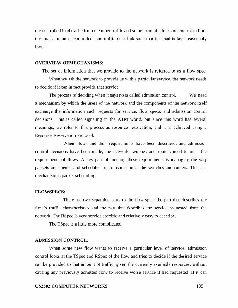
CS2302 COMPUTER NETWORKS
105
the controlled load traffic from the other traffic and some form of admission control to limit
the total amount of controlled load traffic on a link such that the load is kept reasonably
low.
OVERVIEW OFMECHANISMS:
The set of information that we provide to the network is referred to as a flow spec.
When we ask the network to provide us with a particular service, the network needs
to decide if it can in fact provide that service.
The process of deciding when it says no is called admission control. We need
a mechanism by which the users of the network and the components of the network itself
exchange the information such requests for service, flow specs, and admission control
decisions. This is called signaling in the ATM world, but since this word has several
meanings, we refer to this process as resource reservation, and it is achieved using a
Resource Reservation Protocol.
When flows and their requirements have been described, and admission
control decisions have been made, the network switches and routers need to meet the
requirements of flows. A key part of meeting these requirements is managing the way
packets are queued and scheduled for transmission in the switches and routers. This last
mechanism is packet scheduling.
FLOWSPECS:
There are two separable parts to the flow spec: the part that describes the
flow‟s traffic characteristics and the part that describes the service requested from the
network. The RSpec is very service specific and relatively easy to describe.
The TSpec is a little more complicated.
ADMISSION CONTROL:
When some new flow wants to receive a particular level of service, admission
control looks at the TSpec and RSpec of the flow and tries to decide if the desired service
can be provided to that amount of traffic, given the currently available resources, without
causing any previously admitted flow to receive worse service it had requested. If it can
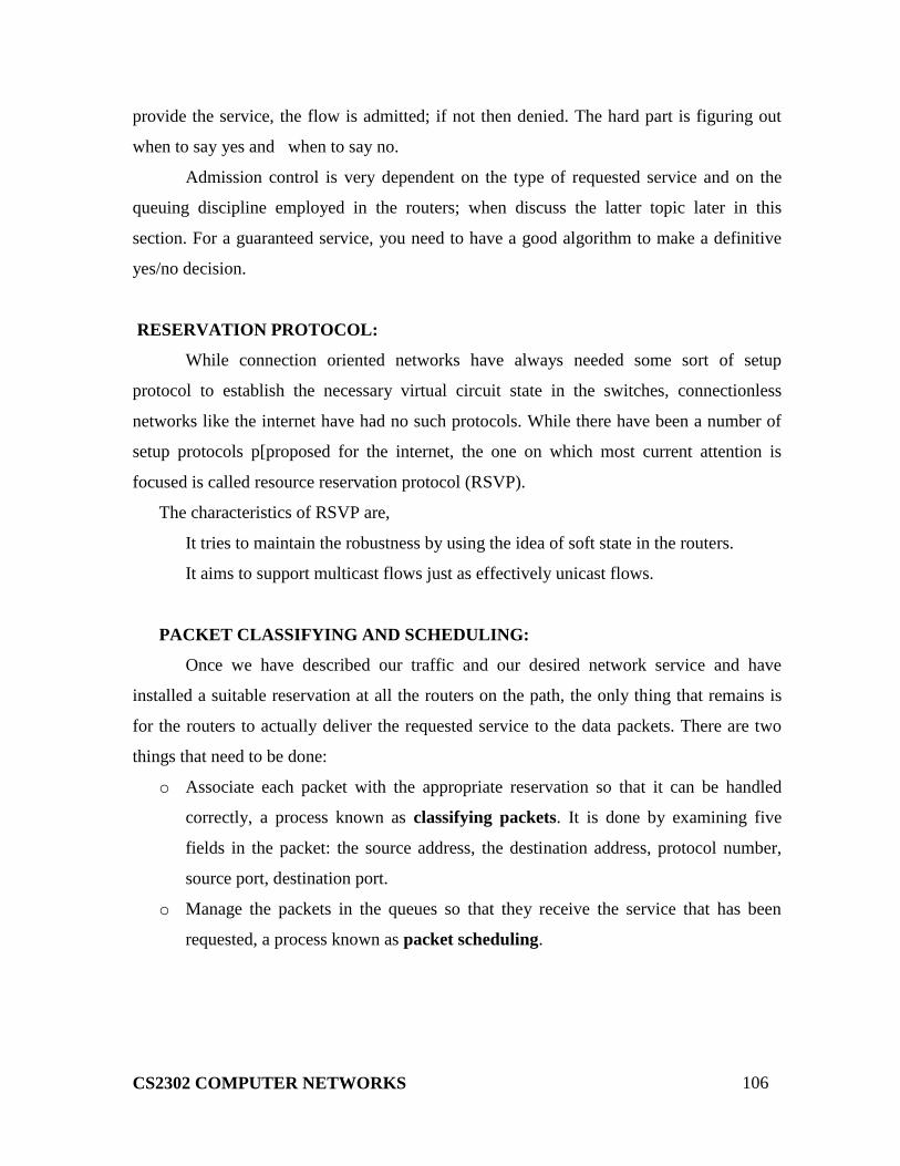
CS2302 COMPUTER NETWORKS
106
provide the service, the flow is admitted; if not then denied. The hard part is figuring out
when to say yes and when to say no.
Admission control is very dependent on the type of requested service and on the
queuing discipline employed in the routers; when discuss the latter topic later in this
section. For a guaranteed service, you need to have a good algorithm to make a definitive
yes/no decision.
RESERVATION PROTOCOL:
While connection oriented networks have always needed some sort of setup
protocol to establish the necessary virtual circuit state in the switches, connectionless
networks like the internet have had no such protocols. While there have been a number of
setup protocols p[proposed for the internet, the one on which most current attention is
focused is called resource reservation protocol (RSVP).
The characteristics of RSVP are,
It tries to maintain the robustness by using the idea of soft state in the routers.
It aims to support multicast flows just as effectively unicast flows.
PACKET CLASSIFYING AND SCHEDULING:
Once we have described our traffic and our desired network service and have
installed a suitable reservation at all the routers on the path, the only thing that remains is
for the routers to actually deliver the requested service to the data packets. There are two
things that need to be done:
o Associate each packet with the appropriate reservation so that it can be handled
correctly, a process known as classifying packets. It is done by examining five
fields in the packet: the source address, the destination address, protocol number,
source port, destination port.
o Manage the packets in the queues so that they receive the service that has been
requested, a process known as packet scheduling.

CS2302 COMPUTER NETWORKS
107
CS2302 COMPUTER NETWORKS
UNIT V 9
Email (SMTP, MIME, IMAP, POP3) – HTTP – DNS- SNMP – Telnet – FTP – Security –
PGP - SSH
NAME SERVICE (DNS):
We have been using address to identify hosts. While perfectly suited for
processing by routers, addresses are not exactly user friendly. It is for this reason that a
unique name is also typically assigned to each host in a network.
A naming service can be developed to map user-friendly names into router-
friendly addresses. Name services are some times called middleware because they fill a
gap between applications and the underlying network.
Host names differ from host addresses in two important ways. First, they are
usually of variable length and mnemonic, thereby making them easier for humans to
remember. (In contrast, fixed-length numeric addresses are easier for routers to
process).Second, names typically contain no information that helps the network locate
(route packets toward) the host. Addresses, in contrast, sometimes have routing
information embedded in them; flat addresses (those not divisible into component parts)
are the exception.
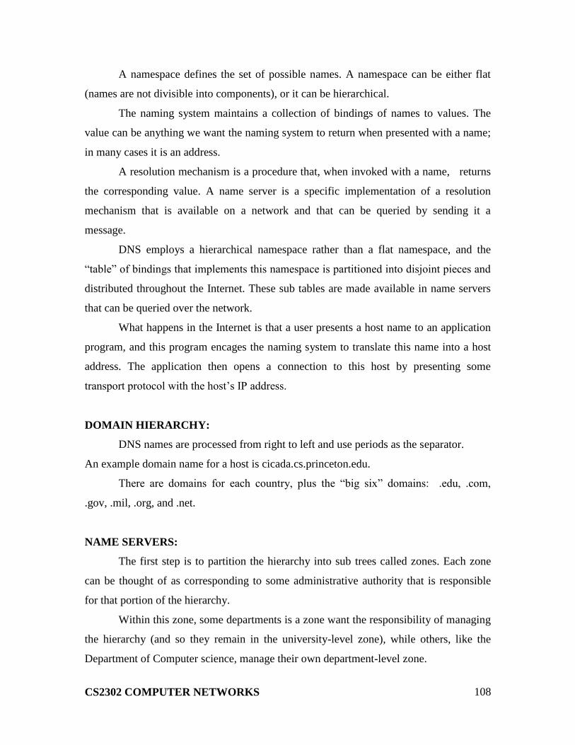
CS2302 COMPUTER NETWORKS
108
A namespace defines the set of possible names. A namespace can be either flat
(names are not divisible into components), or it can be hierarchical.
The naming system maintains a collection of bindings of names to values. The
value can be anything we want the naming system to return when presented with a name;
in many cases it is an address.
A resolution mechanism is a procedure that, when invoked with a name, returns
the corresponding value. A name server is a specific implementation of a resolution
mechanism that is available on a network and that can be queried by sending it a
message.
DNS employs a hierarchical namespace rather than a flat namespace, and the
“table” of bindings that implements this namespace is partitioned into disjoint pieces and
distributed throughout the Internet. These sub tables are made available in name servers
that can be queried over the network.
What happens in the Internet is that a user presents a host name to an application
program, and this program encages the naming system to translate this name into a host
address. The application then opens a connection to this host by presenting some
transport protocol with the host‟s IP address.
DOMAIN HIERARCHY:
DNS names are processed from right to left and use periods as the separator.
An example domain name for a host is cicada.cs.princeton.edu.
There are domains for each country, plus the “big six” domains: .edu, .com,
.gov, .mil, .org, and .net.
NAME SERVERS:
The first step is to partition the hierarchy into sub trees called zones. Each zone
can be thought of as corresponding to some administrative authority that is responsible
for that portion of the hierarchy.
Within this zone, some departments is a zone want the responsibility of managing
the hierarchy (and so they remain in the university-level zone), while others, like the
Department of Computer science, manage their own department-level zone.

CS2302 COMPUTER NETWORKS
109
The relevance of a zone is that it corresponds to the fundamental unit of
implementation in DNS-the name server. Specifically, the information contained in each
zone is implemented in two or more name servers.
Each name server, in turn, is a program that can be accessed over the Internet.
Clients send queries to name servers, and name servers respond with the requested
information. Sometimes the response contains the final answer that the client wants, and
sometimes the response contains a pointer to another that the client should query next.
Each name server implements the zone information as a collection of resource
records. In essence, a resource record is a name-to-value binding, or more specifically, a
5-tuple that contains the following fields:
< Name, Value, Type, Class, TTL >
The Name and Value fields are exactly what you would expect, while the Type
field specifies how the Value should be interpreted. For example, Type=A indicates that
the Value is in IP address. Thus, A records implement the name-to-address mapping we
have been assuming.
Other record types include
NS: The Value field gives the domain name for a host is running a
name server that knows how to resolve names within the specified
domain.
CNAME: the Value field gives the canonical name for a particular
host; it is used to define aliases.
MX: The Value field gives the domain name for a host that is
running a mail server that accepts the messages for the specified
domain.

CS2302 COMPUTER NETWORKS
110
The Class field was included to allow entities other than the NIC to define useful
record types. To date, the only widely used Class is the one used by the Internet; it is
denoted IN. Finally, the TTL field shows how long this resource record is valid. It is used
by servers that cache resource records from other servers; when the TTL expires, the
server must evict the record from its cache.
NAME RESOLUTION
HTTP (HYPERTEXT TRANSFER PROTOCOL)
The Hypertext Transfer Protocol (HTTP) is a protocol used mainly to access data
on the World Wide Web. The protocol transfer all data in the form of plain text,
hypertext, audio, video, and so on. However it is called the hypertext transfer protocol
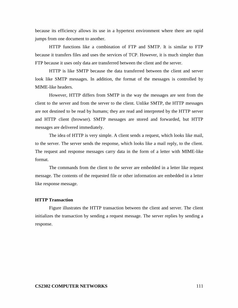
CS2302 COMPUTER NETWORKS
111
because its efficiency allows its use in a hypertext environment where there are rapid
jumps from one document to another.
HTTP functions like a combination of FTP and SMTP. It is similar to FTP
because it transfers files and uses the services of TCP. However, it is much simpler than
FTP because it uses only data are transferred between the client and the server.
HTTP is like SMTP because the data transferred between the client and server
look like SMTP messages. In addition, the format of the messages is controlled by
MIME-like headers.
However, HTTP differs from SMTP in the way the messages are sent from the
client to the server and from the server to the client. Unlike SMTP, the HTTP messages
are not destined to be read by humans; they are read and interpreted by the HTTP server
and HTTP client (browser). SMTP messages are stored and forwarded, but HTTP
messages are delivered immediately.
The idea of HTTP is very simple. A client sends a request, which looks like mail,
to the server. The server sends the response, which looks like a mail reply, to the client.
The request and response messages carry data in the form of a letter with MIME-like
format.
The commands from the client to the server are embedded in a letter like request
message. The contents of the requested file or other information are embedded in a letter
like response message.
HTTP Transaction
Figure illustrates the HTTP transaction between the client and server. The client
initializes the transaction by sending a request message. The server replies by sending a
response.
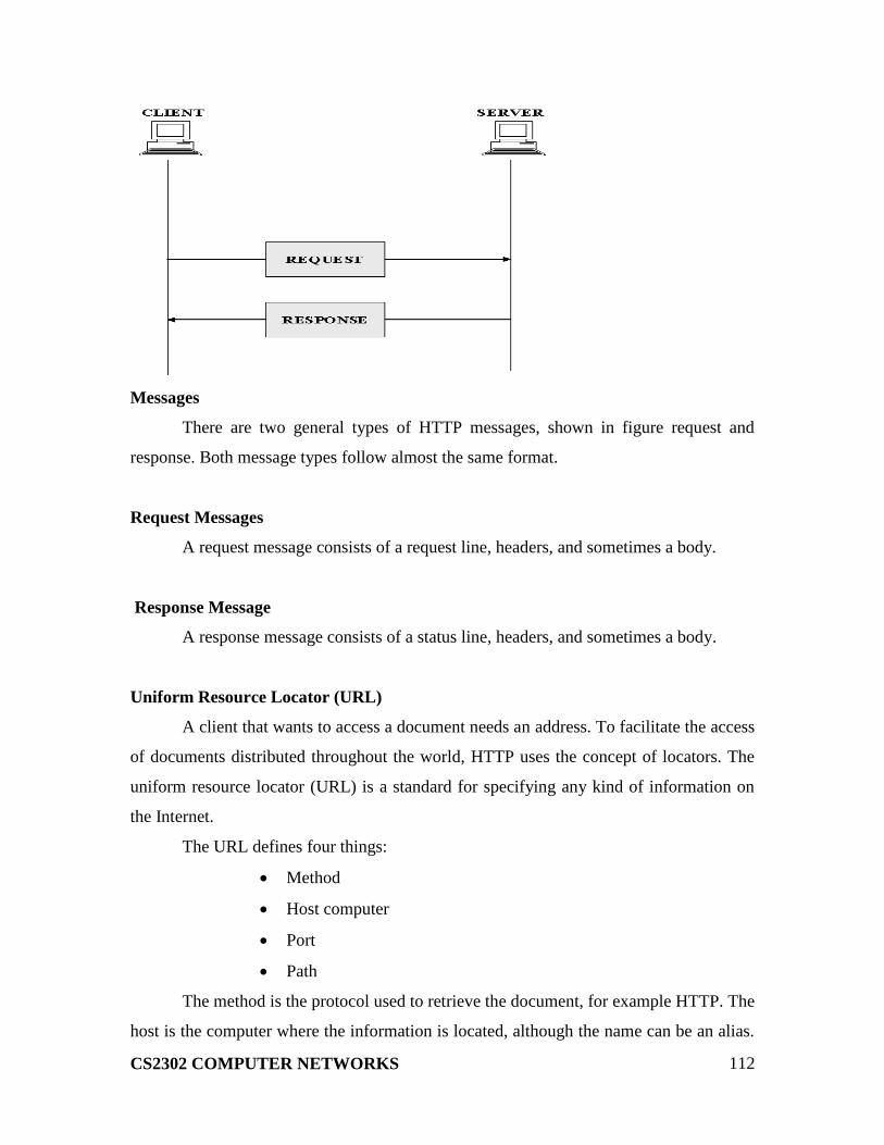
CS2302 COMPUTER NETWORKS
112
Messages
There are two general types of HTTP messages, shown in figure request and
response. Both message types follow almost the same format.
Request Messages
A request message consists of a request line, headers, and sometimes a body.
Response Message
A response message consists of a status line, headers, and sometimes a body.
Uniform Resource Locator (URL)
A client that wants to access a document needs an address. To facilitate the access
of documents distributed throughout the world, HTTP uses the concept of locators. The
uniform resource locator (URL) is a standard for specifying any kind of information on
the Internet.
The URL defines four things:
Method
Host computer
Port
Path
The method is the protocol used to retrieve the document, for example HTTP. The
host is the computer where the information is located, although the name can be an alias.
CS2302 COMPUTER NETWORKS
113
Web pages are usually stored in computers, and computers are given alias names that
usually begin with the characters “www”. This is not mandatory, however, as the host
can be any name given to the computer that hosts the web page.
The URL optionally can contain the port number of the server. If the port is
included, it should be inserted between the host and the path, and it should be separated
from the host by a colon.
Path is the pathname of the file where the information is located. Note that the
path can itself contain slashes that, in the UNIX operating system, separate the directories
from subdirectories and files.
WORLD WIDE WEB (WWW)
The World Wide Web (WWW), or the web, is a repository of information spread
all over the world and linked together. The WWW has a unique combination of
flexibility, portability, and user-friendly features that distinguish it from other services
provided by the Internet.
The WWW project was initiated by CERN (European Laboratory for Particle
Physics) to create a system to handle distributed resources necessary for scientific
research.
The WWW today is a distributed client-server service, in which a client using a
browser can access a service using a server. However, the service provided is distributed
over many locations called web sites.
Hypertext and Hypermedia
The WWW uses the concept of hypertext and hypermedia. In a hypertext
environment, information is stored in a set of documents that are linked together using
the concept of pointers. An item can be associated with another document using a pointer.
The reader who is browsing through the document move to other documents by
choosing (clicking) the items that are linked to other documents. Figure shows the
concept of hypertext.
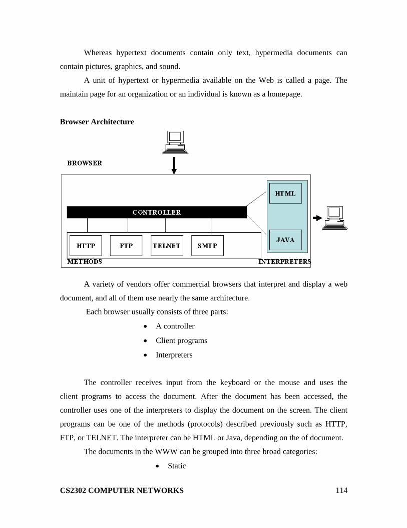
CS2302 COMPUTER NETWORKS
114
Whereas hypertext documents contain only text, hypermedia documents can
contain pictures, graphics, and sound.
A unit of hypertext or hypermedia available on the Web is called a page. The
maintain page for an organization or an individual is known as a homepage.
Browser Architecture
A variety of vendors offer commercial browsers that interpret and display a web
document, and all of them use nearly the same architecture.
Each browser usually consists of three parts:
A controller
Client programs
Interpreters
The controller receives input from the keyboard or the mouse and uses the
client programs to access the document. After the document has been accessed, the
controller uses one of the interpreters to display the document on the screen. The client
programs can be one of the methods (protocols) described previously such as HTTP,
FTP, or TELNET. The interpreter can be HTML or Java, depending on the of document.
The documents in the WWW can be grouped into three broad categories:
Static

CS2302 COMPUTER NETWORKS
115
Dynamic
Active
The category is based on the time when the contents of the document are
determined.
Static Documents
Static documents are fixed–content documents that are created and stored in a
server. The client can get only a copy of the document. In other words, the contents of the
file are determined when the file is created, not when it is used. Of course, the contents in
the server can be changed, but the user cannot change it. When a client accesses the
document, a copy of the document is sent. The user can use a browsing program to
display the document.
FILE TRANSFER PROTOCOL (FTP)
File transfer protocol (FTP) is the standard mechanism provided by TCP/IP for
copying a file from one host to another. Transferring files from one computer to another
is one of the most common tasks expected from a networking or internetworking
environment.
Although transferring files from one system to another seems simple and straight-
forward. Some problems must be dealt with first. For example, two systems may use

CS2302 COMPUTER NETWORKS
116
different file name conventions. Two systems may have different ways to represent text
and data. Two systems may have different directory structures. All of these problems
have been solved by FTP in a very simple and elegant approach.
FTP differs from other client-server applications in that it establishes two
connections between the hosts. One connection is used for data transfer, the other for
control information (commands and responses). Separation of commands and data
transfer makes FTP more efficient. The control connection uses very simple rules of
communication. On the other hand, needs more complex rules due to the variety of data
types transferred.
The client has three components:
The user interface
The client control process
The client data transfer process
The server has two components:
The server control process
Server data transfer process
The control connection is made between the control processes. The data
connection is made between the data transfer processes.
The control connection remains connected during the entire interactive FTP
session. The data connection is opened and then closed for each file transferred. It opens
each time commands that involve transferring files are used, and it closes when the file is
transferred. The two FTP connections, control and data, use different strategies and
different port numbers.
TRIVIAL FILE TRANSFER PROTOCOL (TFTP)
There are occasions when we need to simply copy a file without the need for all
of the functionalities of the FTP protocol. For example, when a diskless workstation or a
router is booted, we need to download the bootstrap and configuration files. Here we do

CS2302 COMPUTER NETWORKS
117
not need all of the sophistication provided in FTP. We just need a protocol that quickly
copies the files.
Trivial File Transfer Protocol (TFTP) is designed for these types of file transfer. It
is so simple that the software package can fit into the read-only memory of a diskless
workstation. It can be used at bootstrap time.
TFTP can read or write a file for the client. Reading means copying a file from
the server site to the client site. Writing means copying a file from client site to the server
site.
FOUR ASPECTS OF SECURITY
Based on the above expectations, we can say that security involves four aspects:
Privacy(confidentiality)
Message authentication
Message integrity
Non-repudiation
Privacy
Privacy means that the sender and the receiver expect confidentially. The
transmitted message should make sense to only the intended receiver. To all other
message should be unintelligible.
Authentication
Authentication means that the receiver is sure of the sender‟s identity and that an
imposter has not sent the message.
Integrity
Data integrity means that the data must arrive at the receiver exactly as it was
sent. There must be no changes during the transmission, either accidental or malicious.
As more and more monetary exchanges occur over the Internet, integrity is crucial. For
example, it would be disastrous if a request for transferring $100 changes to a request for

CS2302 COMPUTER NETWORKS
118
$10,000 or $100,000. The integrity of the message must be preserved in a secure
communication.
Non-Repudiation
Non-repudiation means that a receiver must be able to prove that a received
message came from a specific sender. The sender must be able to deny sending a message
that he, in fact did send. The burden of proof falls on the receiver. For example, when a
customer sends a message to transfer money from one account to another, the bank must
have proof that the customer actually requested this transaction.
Electronic Mail(SMTP,MIME,IMAP)
Email is one of the oldest network applications.How email works is to
(1)distinguish the user interface(i.e your mail reader) from the
underlying message transfer protocol (in this case,SMTP),and
(2)to distinguish between this transfer protocol and a companion
protocol(RFC 822 and
Message Format
RFC 822 defines messages to have two parts: a header and a body. Both parts
are represented in ASCII text. Originally, the body was assumed to be simple text. This is
still the case, although RFC 822 has been augmented by MIME to allow the message
body to carry all sorts of data. This data is still represented as ASCII text, but because it
may be an encoded version of, say a JPEG image, it‟s not necessarily readable by human
users.
More on MIME in a moment.
The message header is a series of <CRLF> terminated lines.(<CRLF> stands
for carriage-return + line-feed, which are a pair of ASCII control characters often used to
indicate the end of a line of text.) The header is separated from the message body by a
blank line. Each header line contains a type and value separated by a colon. Many of
CS2302 COMPUTER NETWORKS
119
these header lines are familiar to users since they are asked to fill them out when they
compose an email message. For example ,the To:header identifies the message recipient ,
and the Subject:header says something about the purpose of the message. Other headers
are filled in by the underlying mail delivery system.Examples include Date: (when the
message was transmitted).From: (what user sent the message),and Received: (each mail
server that handled this message).There are, of course ,many other header lines;the
interested reader is referred to RFC 822.
These header lines describe, in various ways ,the data being carried in the
message body. They include MIME-Version: (the version of MIME being used),
Content-Description: ( a human –readable description of what‟s in the
message,analogous to the Subject:line),Content-Type:the type of data contained in the
message),and Content-Transfer-Encoding(how the message body is encoded)
The second piece is definitions for a set of content types(and subtypes).For
example ,MIME defines two different still-image types, denoted image/gif and
image/jpeg,each with the obvious meaning. As another example ,text/plain refers to
simple text you might find in a vanilla 822-style message ,while text/richtext denotes a
message that contains “marked up” text (text using special fonts , italics, etc).As a third
example, MIME defines an application type , where the subtypes correspond to the
output of different application programs(eg.,application/postscript and
application/msword).
MIME also defines a multipart type that says how a message carrying more
than one data type is structured. This is like a programming language that defines both
base types(eg.,integers and floats) and compound types (eg.,. structures and arrays).One
possible multipart subtype is mixed ,which says that the message contains a set of
independent data pieces in a specified order. Each piece then has its own header line that
describes the type of that piece.
The third piece is a way to encode the various data types so they can be shipped
in an ASCII email message. The problem is that for some data types(a JPEG image, for
example),any given 8-bit byte in the image might contain one of 256 different values.
Only a subset of these values are valid ASCII characters .It is important that email
CS2302 COMPUTER NETWORKS
120
messages contain only ASCII ,because they might pass through a number of intermediate
systems(gateways ,as described below) that assume all email is ASCII and would corrupt
the message if it contained non-ASCII characters .To address this issue ,MIME uses a
straightforward encoding of binary data into the ASCII character.The encoding is called
base64.The idea is to map every three bytes of the original binary data into four ASCII
characters .This is done by grouping the binary data into 24-bit units ,and breaking each
such unit into four 6-bit pieces .Each 6-bit piece maps onto one of 64 valid ASCII
character;for example ,0maps onto A,1 maps onto B ,and so on.If you look at a message
that has been encoded using the base 64 encoding scheme,you will notice only the 52
uppercase and lowercase letters ,the 10 digits through 0 to9 ,and the special characters +
and /.These are the first 64 values in the ASCII character set.
Message Transfer:
Next we look at SMTP- the protocol used to transfer messages from one host to
another. To place SMTP in the right context, we need to identify the key players. First,
users interact with a mail reader when they compose ,file ,search, and read their email.
There are countless mail readers available ,just like there are many web browsers now
include a mail reader. Second ,there is a mail daemon running on each host. You can
think of this process as playing the role of a post office :mail readers give the daemon
messages they want to send to others users, the daemon uses SMTP running over TCP to
transmit the message into a daemon running on another machine, and the daemon puts
incoming messages into the user‟s mailbox. Since SMTP is a protocol that anyone could
implement , in theory there could be many different implementations of the mail daemon.
It runs out, though that the mail daemon running on most hosts is derived from the
sendmail program originally implemented on berkely unix.

CS2302 COMPUTER NETWORKS
121
While it is certainly possible that the sendmail program on a sender‟s
machine establishes an SMTP/TCP connection to the sendmail program on the recipient‟s
machine, in many cases the mail traverses one or more mail gateways on its route from
the sender‟s host to the receiver‟s host. Like the end hosts, these gateways also run a
send-mail process. It‟s not an accident that these intermediate nodes are called
“gateways” since their job is to store and forward email messages.
Mail Reader:
The final step is for the user to actually receive her messages from the mail box,
read them ,reply to them, and possibly save a copy for future reference .The user
performs all the actions by interacting with a mail reader. In many cases ,this reader is
just a program running on the same machine as the user‟s mailbox resides, in which case
it simply reads and writes the file that implements the mailbox .In other cases ,the user
accesses her mailbox from a remote machine using yet another protocol, such as the Post
Office Protocol(POP) or the Internet Message Access Control(IMAP).It is beyond the
scope of this book to discuss the user interface aspects of the mail reader but it is
definitely within our scope to talk about the access protocol. We consider IMAP, in
particular.
IMAP is similar to SMTP in many ways .It is a client/server protocol running
over TCP, where the client (running on the user‟s desktop machine) issues commands in
the form of <CRLF> terminated ASCII text lines and the mail server(running on the

CS2302 COMPUTER NETWORKS
122
machine that maintains the user‟s mailbox) responds in-kind. The exchange begins with
the client authenticating herself, and identifying the mailbox she wants to access. This
can be represented by the simple state transaction diagram shown in the figure. In this
diagram, LOGIN, AUTHENTICATE, SELECT, EXAMINE, CLOSE and LOGOUT are
example commands that the client can issue, while OK is one possible server response.
Other common commands include FETCH, STORE, DELETE, and EXPUNGE, with the
obvious meanings. Additional server responds include NO (client does not have
permission to perform that operation) and BAD (command is ill-formed).
When the user asks to FETCH a message, the server returns it in MIME format
and the mail reader decodes it. In addition to the message itself, IMAP also defines a set
of message attributes that are exchanged as part of other commands, independent of
transferring the message itself. Message attributes include information like the size of the
message, but more interestingly, various flags associated with a message, such as Seen,
Answered, Deleted and Recent. These flags are used to keep the client and server
synchronized, that is, when the user deletes a message in the mail reader, the client needs
to report this fact to the mail server. Later, should the user decide to expunge all deleted
messages, the client issues an EXPUNGE command to the server, which knows to
actually remove all earlier deleted messages from the mail box.
Finally, note that when the user replies to a message,or sends a new message,
the mail reader does not forward the message from the client to the mail server using
IMAP ,but it instead uses SMTP .This means that the user‟s mail server is effectively the
first mail gateway traversed along the path from the desktop to the recipient‟s mail box.