Unit I - csnow.in understanding of the fundamentals of the OSI model provides a solid basis for...
28
Unit – I OSI Model: The purpose of the OSI model is to show how to facilitate communication between different systems without requiring changes to the logic of the underlying hardware and software. The OSI model is not a protocol; it is a model for understanding and designing a network architecture that is flexible, robust, and interoperable. ISO is the organization. OSI is the model. The OSI model is a layered framework for the design of network systems that allows communication between all types of computer systems. It consists of seven separate but related layers, each of which defines a part of the process of moving information across a network (see Figure 2.2). An understanding of the fundamentals of the OSI model provides a solid basis for exploring data communications. The OSI model is composed of seven ordered layers: physical (layer 1), data link (layer 2), network (layer 3), transport (layer 4), session (layer 5), presentation (layer 6) and application (layer 7). Figure 2.3 shows the layers involved when a message is sent from device A to device B. As the message travels from A to B, it may pass through many intermediate nodes. These intermediate nodes usually involve only the first three layers of the OSI model. In developing the model, the designers distilled the process of transmitting data to its most fundamental elements. They identified which networking functions had related uses and collected those functions into discrete groups that became the layers. Each layer defines a family of functions distinct from those of the other layers. By defining and localizing functionality in this fashion, the designers created an architecture that is both comprehensive and flexible. Most importantly, the OSI model allows complete interoperability between otherwise incompatible systems. Physical Layer The physical layer coordinates the functions required to carry a bit stream over a physical medium. It deals with the mechanical and electrical specifications of the interface and transmission
Transcript of Unit I - csnow.in understanding of the fundamentals of the OSI model provides a solid basis for...

Unit – I
OSI Model:
The purpose of the OSI model is to show how to facilitate communication between different
systems without requiring changes to the logic of the underlying hardware and software. The OSI
model is not a protocol; it is a model for understanding and designing a network architecture that is
flexible, robust, and interoperable. ISO is the organization. OSI is the model.
The OSI model is a layered framework for the design of network systems that allows
communication between all types of computer systems. It consists of seven separate but related
layers, each of which defines a part of the process of moving information across a network (see Figure
2.2). An understanding of the fundamentals of the OSI model provides a solid basis for exploring data
communications.
The OSI model is composed of seven ordered layers: physical (layer 1), data link (layer 2),
network (layer 3), transport (layer 4), session (layer 5), presentation (layer 6) and application (layer 7).
Figure 2.3 shows the layers involved when a message is sent from device A to device B. As the message
travels from A to B, it may pass through many intermediate nodes. These intermediate nodes usually
involve only the first three layers of the OSI model.
In developing the model, the designers distilled the process of transmitting data to its most
fundamental elements. They identified which networking functions had related uses and collected
those functions into discrete groups that became the layers. Each layer defines a family of functions
distinct from those of the other layers. By defining and localizing functionality in this fashion, the
designers created an architecture that is both comprehensive and flexible. Most importantly, the OSI
model allows complete interoperability between otherwise incompatible systems.
Physical Layer
The physical layer coordinates the functions required to carry a bit stream over a physical
medium. It deals with the mechanical and electrical specifications of the interface and transmission

medium. It also defines the procedures and functions that physical devices and interfaces have to
perform for transmission to Occur.
Data Link Layer:
The data link layer transforms the physical layer, a raw transmission facility, to a reliable link. It makes
the physical layer appear error-free to the upper layer (network layer).
Network Layer:
The network layer is responsible for the source-to-destination delivery of a packet, possibly
across multiple networks (links). Whereas the data link layer oversees the delivery of the packet
between two systems on the same network (links), the network layer ensures that each packet gets
from its point of origin to its final destination.
Transport Layer:
The transport layer is responsible for process-to-process delivery of the entire message. A
process is an application program running on a host. Whereas the network layer oversees source-to-
destination delivery of individual packets, it does not recognize any relationship between those
packets. It treats each one independently, as though each piece belonged to a separate message,
whether or not it does. The transport layer, on the other hand, ensures that the whole message arrives
intact and in order, overseeing both error control and flow control at the source-to-destination level.
Session Layer:
The services provided by the first three layers (physical, data link, and network) are not
sufficient for some processes. The session layer is the network dialog controller. It establishes,
maintains, and synchronizes the interaction among communicating systems.
Presentation Layer:
The presentation layer is concerned with the syntax and semantics of the information
exchanged between two systems.
Application Layer:
The application layer enables the user, whether human or software, to access the network. It
provides user interfaces and support for services such as electronic mail, remote file access and
transfer, shared database management, and other types of distributed information services.
Peer-to-Peer Processes:
At the physical layer, communication is direct: In Figure 2.3, device A sends a stream of bits to
device B (through intermediate nodes). At the higher layers, however, communication must move
down through the layers on device A, over to device B, and then back up through the layers. Each layer
in the sending device adds its own information to the message it receives from the layer just above it
and passes the whole package to the layer just below it.
At layer I the entire package is converted to a form that can be transmitted to the receiving
device. At the receiving machine, the message is unwrapped layer by layer, with each process receiving
and removing the data meant for it. For example, layer 2 removes the data meant for it, then passes
the rest to layer 3. Layer 3 then removes the data meant for it and passes the rest to layer 4, and so
on.

TCP/IP PROTOCOL SUITE:
The TCPIIP protocol suite was developed prior to the OSI model. Therefore, the layers in the
TCP/IP protocol suite do not exactly match those in the OSI model. The original TCP/IP protocol suite
was defined as having four layers: host-to-network, internet, transport, and application. However,
when TCP/IP is compared to OSI, we can say that the host-to-network layer is equivalent to the
combination of the physical and data link layers. The internet layer is equivalent to the network layer,
and the application layer is roughly doing the job of the session, presentation, and application layers
with the transport layer in TCP/IP taking care of part of the duties of the session layer.
The first four layers provide physical standards, network interfaces, internetworking, and
transport functions that correspond to the first four layers of the OSI model. The three topmost layers
in the OSI model, however, are represented in TCPIIP by a single layer called the application layer.
At the transport layer, TCP/IP defines three protocols: Transmission Control Protocol (TCP),
User Datagram Protocol (UDP), and Stream Control Transmission Protocol (SCTP). At the network
layer, the main protocol defined by TCP/IP is the Internetworking Protocol (IP); there are also some
other protocols that support data movement in this layer.
Physical and Data Link Layers:
At the physical and data link layers, TCPIIP does not define any specific protocol. It supports all the
standard and proprietary protocols. A network in a TCPIIP internetwork can be a local-area network
or a wide-area network.
Network Layer:
At the network layer (or, more accurately, the internetwork layer), TCP/IP supports the
Internetworking Protocol. IP, in turn, uses four supporting protocols: ARP, RARP, ICMP, and IGMP.
Transport Layer:
Traditionally the transport layer was represented in TCP/IP by two protocols: TCP and UDP. IP
is a host-to-host protocol, meaning that it can deliver a packet from one physical device to another.
UDP and TCP are transport level protocols responsible for delivery of a message from a process

(running program) to another process. A new transport layer protocol, SCTP, has been devised to meet
the needs of some newer applications.
Application Layer:
The application layer in TCPIIP is equivalent to the combined session, presentation, and application
layers in the OSI model. Many protocols are defined at this layer.
Network Types:
Local Area Network (LAN):
A local area network (LAN) is usually privately owned and links the devices in a single office,
building, or campus. Depending on the needs of an organization and the type of technology used, a
LAN can be as simple as two PCs and a printer in someone's home office; or it can extend throughout
a company and include audio and video peripherals. Currently, LAN size is limited to a few kilometres.
LANs are designed to allow resources to be shared between personal computers or
workstations. The resources to be shared can include hardware (e.g., a printer), software (e.g., an
application program). Each host in a LAN has an identifier, an address, that that uniquely defines the
host in the LAN. A packet sent by a host to another host carries both the source host’s and the
destination host’s address.
Wide Area Network:
A wide area network (WAN) provides long-distance transmission of data, image, audio, and video
information over large geographic areas that may comprise a country, a continent, or even the whole
world. A WAN can be as complex as the backbones that connect the Internet or as simple as a dial-up
line that connects a home computer to the Internet. We normally refer to the first as a switched WAN
and to the second as a point-to-point WAN.
The switched WAN connects the end systems, which usually comprise a router (internetworking
connecting device) that connects to another LAN or WAN.
The point-to-point WAN is normally a line leased from a telephone or cable TV provider that connects
a home computer or a small LAN to an Internet service provider (ISP). This type of WAN is often used
to provide Internet access.

Metropolitan Area Networks:
A metropolitan area network (MAN) is a network with a size between a LAN and a WAN. It
normally covers the area inside a town or a city. It is designed for customers who need a high-speed
connectivity, normally to the Internet, and have endpoints spread over a city or part of city. A good
example of a MAN is the part of the telephone company network that can provide a high-speed DSL
line to the customer. Another example is the cable TV network that originally was designed for cable
TV, but today can also be used for high-speed data connection to the Internet.
GUIDED MEDIA:
Guided media, which are those that provide a conduit from one device to another, include
twisted-pair cable, coaxial cable, and fiber-optic cable. A signal traveling along any of these media is
directed and contained by the physical limits of the medium. Twisted-pair and coaxial cable use
metallic (copper) conductors that accept and transport signals in the form of electric current. Optical
fiber is a cable that accepts and transports signals in the form of light.
Twisted-Pair Cable:
A twisted pair consists of two conductors (normally copper), each with its own plastic
insulation, twisted together, as shown in Figure.
One of the wires is used to carry signals to the receiver, and the other is used only as a
ground reference. The receiver uses the difference between the two.
In addition to the signal sent by the sender on one of the wires, interference (noise) and
crosstalk may affect both wires and create unwanted signals.
If the two wires are parallel, the effect of these unwanted signals is not the same in both
wires because they are at different locations relative to the noise or crosstalk sources (e.g., one is
closer and the other is farther). This results in a difference at the receiver. By twisting the pairs, a
balance is maintained.
Coaxial Cable:
Coaxial cable (or coax) carries signals of higher frequency ranges than those in twisted – pair
cable, in part because the two media are constructed quite differently. Instead of having two wires,
coax has a central core conductor of solid or stranded wire (usually copper) enclosed in an insulating
sheath, which is, in turn, encased in an outer conductor of metal foil, braid, or a combination of the
two. The outer metallic wrapping serves both as a shield against noise and as the second conductor,
which completes the circuit.
This outer conductor is also enclosed in an insulating sheath, and the whole cable is protected
by a plastic cover.
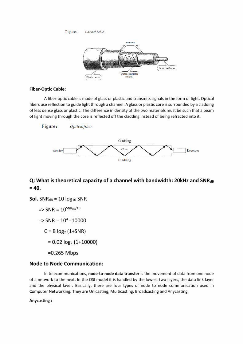
Fiber-Optic Cable:
A fiber-optic cable is made of glass or plastic and transmits signals in the form of light. Optical
fibers use reflection to guide light through a channel. A glass or plastic core is surrounded by a cladding
of less dense glass or plastic. The difference in density of the two materials must be such that a beam
of light moving through the core is reflected off the cladding instead of being refracted into it.
Q: What is theoretical capacity of a channel with bandwidth: 20kHz and SNRdB
= 40.
Sol. SNRdB = 10 log10 SNR
=> SNR = 10SNRdB/10
=> SNR = 104 =10000
C = B log2 (1+SNR)
= 0.02 log2 (1+10000)
=0.265 Mbps
Node to Node Communication:
In telecommunications, node-to-node data transfer is the movement of data from one node
of a network to the next. In the OSI model it is handled by the lowest two layers, the data link layer
and the physical layer. Basically, there are four types of node to node communication used in
Computer Networking. They are Unicasting, Multicasting, Broadcasting and Anycasting.
Anycasting :

When a source node sends a packet or frame to a special destination IP address known as
Anycast IP address, then it is termed as Anycast communication. Anycasting has been introduced only
in IPV6 and is not present in IPV4.
Process to process communication:
Inter-process communication (IPC) is a set of programming interfaces that allow a
programmer to coordinate activities among different program processes that can run concurrently in
an operating system. This allows a program to handle many user requests at the same time. Since
even a single user request may result in multiple processes running in the operating system on the
user's behalf, the processes need to communicate with each other. The IPC interfaces make this
possible. Each IPC method has its own advantages and limitations so it is not unusual for a single
program to use all of the IPC methods.
Q: Why we define a LAN on behalf of distance?
Ans.
LAN technologies are designed with constraints of speed, distance, and cost.
A typical LAN technology can span, at most, a few hundred meters. LANs are not designed for
long distances.
The need for fair access on shared media such as Ethernet and token ring limits the size of a
LAN.
- CSMA/CD doesn’t work satisfactorily when a network gets too big.
- Neither does token passing.
Signal strength and noise become serious problems over long distances
Repeater:
A bidirectional analog amplifier that amplifies and retransmits signals.
A repeater can be used to extend the size of a LAN medium.
One repeater can effectively double the length of a LAN segment.
Example: An Ethernet repeater can double the maximum size of an Ethernet segment from
500 meters to 1000 meters.
Ethernet can’t be extended indefinitely with repeaters. CSMA/CD requires low delay and
won’t work on a long medium
Bridge:
A hardware device that connects two LAN segments and copies frames from one to the other.
Like a repeater, a bridge connects two LAN segments.
Unlike a repeater, a bridge understands and retransmits complete frames.
- Uses a NIC like any other station.
- Can perform additional frame processing.
A bridge is invisible to other attached computers.
Unit- II
Physical Layer
Physical Structures
Type of Connection:
A network is two or more devices connected through links. A link is a communications pathway that
transfers data from one device to another. For visualization purposes, it is simplest to imagine any
link as a line drawn between two points. For communication to occur, two devices must be
connected in some way to the same link at the same time.
There are two possible types of connections: point-to-point and multipoint.
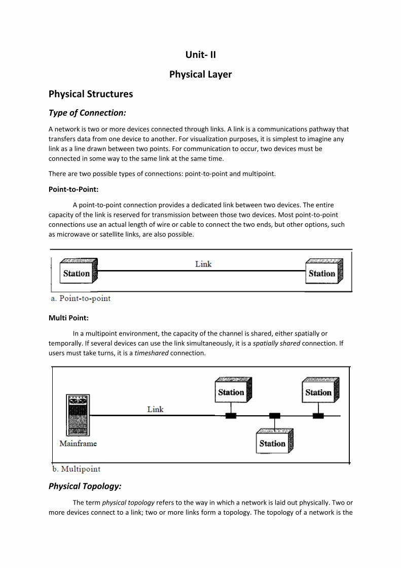
Point-to-Point:
A point-to-point connection provides a dedicated link between two devices. The entire
capacity of the link is reserved for transmission between those two devices. Most point-to-point
connections use an actual length of wire or cable to connect the two ends, but other options, such
as microwave or satellite links, are also possible.
Multi Point:
In a multipoint environment, the capacity of the channel is shared, either spatially or
temporally. If several devices can use the link simultaneously, it is a spatially shared connection. If
users must take turns, it is a timeshared connection.
Physical Topology:
The term physical topology refers to the way in which a network is laid out physically. Two or
more devices connect to a link; two or more links form a topology. The topology of a network is the

geometric representation of the relationship of all the links and linking devices to one another. There
are four basic topologies possible: mesh, star, bus, and ring.
Mash:
In a mesh topology, every device has a dedicated point-to-point link to every other device.
The term dedicated means that the link carries traffic only between the two devices it connects. To
find the number of physical links in a fully connected mesh network with n nodes, we first consider
that each node must be connected to every other node. Node 1 must be connected to n - I nodes,
node 2 must be connected to n – 1 nodes, and finally node n must be connected to n - 1 nodes. We
need n(n - 1) physical links. However, if each physical link allows communication in both directions
(duplex mode), we can divide the number of links by 2. In other words, we can say that in a mesh
topology, we need n(n -1) /2 duplex-mode links.
Start:
In a star topology, each device has a dedicated point-to-point link only to a central controller,
usually called a hub. The devices are not directly linked to one another. Unlike a mesh topology, a star
topology does not allow direct traffic between devices. The controller acts as an exchange: If one
device wants to send data to another, it sends the data to the controller, which then relays the data
to the other connected device.
A star topology is less expensive than a mesh topology. In a star, each device needs only one
link and one I/O port to connect it to any number of others. This factor also makes it easy to install
and reconfigure. Far less cabling needs to be housed, and additions, moves, and deletions involve only
one connection: between that device and the hub.
Other advantages include robustness. If one link fails, only that link is affected. All other links
remain active.

BUS:
A bus topology, on the other hand, is multipoint. One long cable acts as a backbone to link all
the devices in a network.
Nodes are connected to the bus cable by drop lines and taps. A drop line is a connection
running between the device and the main cable. A tap is a connector that either splices into the main
cable or punctures the sheathing of a cable to create a contact with the metallic core. As a signal
travels along the backbone, some of its energy is transformed into heat. Therefore, it becomes weaker
and weaker as it travels farther and farther. For this reason there is a limit on the number of taps a
bus can support and on the distance between those taps.
Advantages of a bus topology include ease of installation. Backbone cable can be laid along
the most efficient path, then connected to the nodes by drop lines of various lengths. In this way, a
bus uses less cabling than mesh or star topologies. In a star, for example, four network devices in the
same room require four lengths of cable reaching all the way to the hub. In a bus, this redundancy is
eliminated. Only the backbone cable stretches through the entire facility. Each drop line has to reach
only as far as the nearest point on the backbone.
Ring:
In a ring topology, each device has a dedicated point-to-point connection with only the two
devices on either side of it. A signal is passed along the ring in one direction, from device to device,
until it reaches its destination. Each device in the ring incorporates a repeater. When a device
receives a signal intended for another device, its repeater regenerates the bits and passes them along.
A ring is relatively easy to install and reconfigure. Each device is linked to only its immediate
neighbours (either physically or logically). To add or delete a device requires changing only two
connections. The only constraints are media and traffic considerations (maximum ring length and
number of devices). In addition, fault isolation is simplified. Generally in a ring, a signal is circulating

at all times. If one device does not receive a signal within a specified period, it can issue an alarm. The
alarm alerts the network operator to the problem and its location.
However, unidirectional traffic can be a disadvantage. In a simple ring, a break in the ring (such
as a disabled station) can disable the entire network. This weakness can be solved by using a dual ring
or a switch capable of closing off the break.
Hybrid:
A network can be hybrid. For example, we can have a main star topology with each
branch connecting several stations in a bus topology.
Circuit Switching:
A circuit-switched network consists of a set of switches connected by physical links. A
connection between two stations is a dedicated path made of one or more links. However, each
connection uses only one dedicated channel on each link. Each link is normally divided into n channels
by using FDM or TDM.
A circuit-switched network is made of a set of switches connected by physical links, in which
each link is divided into n channels.

Figure shows a trivial circuit-switched network with four switches and four links. Each link is
divided into n (n is 3 in the figure) channels by using FDM or TDM.
The end systems, such as computers or telephones, are directly connected to a switch. We
have shown only two end systems for simplicity. When end system A needs to communicate with end
system M, system A needs to request a connection to M that must be accepted by all switches as well
as by M itself. This is called the setup phase; a circuit (channel) is reserved on each link, and the
combination of circuits or channels defines the dedicated path. After the dedicated path made of
connected circuits (channels) is established, data transfer can take place. After all data have been
transferred, the circuits are tom down.
We need to emphasize several points here:
Circuit switching takes place at the physical layer.
Before starting communication, the stations must make a reservation for the resources to be
used during the communication. These resources, such as channels (bandwidth in FDM and
time slots in TDM), switch buffers, switch processing time, and switch input/output ports,
must remain dedicated during the entire duration of data transfer until the teardown phase.
Data transferred between the two stations are not packetized (physical layer transfer of the
signal). The data are a continuous flow sent by the source station and received by the
destination station, although there may be periods of silence.
There is no addressing involved during data transfer. The switches route the data based on
their occupied band (FDM) or time slot (TDM). Of course, there is end-to-end addressing used
during the setup phase, as we will see shortly.
In circuit switching, the resources need to be reserved during the setup phase; the resources
remain dedicated for the entire duration of data transfer until the teardown phase.
Packet Switching:

In packet switching, there is no resource allocation for a packet. This means that there is no
reserved bandwidth on the links, and there is no scheduled processing time for each packet. Resources
are allocated on demand. The allocation is done on a first-come, first-served basis. When a switch
receives a packet, no matter what is the source or destination, the packet must wait if there are other
packets being processed. As with other systems in our daily life, this lack of reservation may create
delay. For example, if we do not have a reservation at a restaurant, we might have to wait.
In a datagram network, each packet is treated independently of all others. Even if a packet is
part of a multi-packet transmission, the network treats it as though it existed alone. Packets in this
approach are referred to as datagrams.
In this example, all four packets (or datagrams) belong to the same message, but may travel
different paths to reach their destination. This is so because the links may be involved in carrying
packets from other sources and do not have the necessary bandwidth available to carry all the packets
from A to X. This approach can cause the datagrams of a transmission to arrive at their destination out
of order with different delays between the packets. Packets may also be lost or dropped because of a
lack of resources. In most protocols, it is the responsibility of an upper-layer protocol to reorder the
datagrams or ask for lost datagrams before passing them on to the application.
The datagram networks are sometimes referred to as connectionless networks. The term
connectionless here means that the switch (packet switch) does not keep information about the
connection state. There are no setup or teardown phases. Each packet is treated the same by a switch
regardless of its source or destination.
Virtual Circuit Switching:
A virtual-circuit network is a cross between a circuit-switched network and a datagram
network. It has some characteristics of both.
1. As in a circuit-switched network, there are setup and teardown phases in addition to the data
transfer phase.
2. Resources can be allocated during the setup phase, as in a circuit-switched network, or on
demand, as in a datagram network.
3. As in a datagram network, data are packetized and each packet carries an address in the
header. However, the address in the header has local jurisdiction (it defines what should be
the next switch and the channel on which the packet is being canied), not end-to-end
jurisdiction. The reader may ask how the intermediate switches know where to send the
packet if there is no final destination address carried by a packet. The answer will be clear
when we discuss virtual-circuit identifiers in the next section.

4. As in a circuit-switched network, all packets follow the same path established during the
connection.
5. A virtual-circuit network is normally implemented in the data link layer, while a circuit-
switched network is implemented in the physical layer and a datagram network in the network
layer. But this may change in the future.
Figure shows an example of a virtual-circuit network. The network has switches that allow
traffic from sources to destinations. A source or destination can be a computer, packet switch, bridge,
or any other device that connects other networks.
TDM:
Time-division multiplexing (TDM) is a digital process that allows several connections to share
the high bandwidth of a link. Instead of sharing a portion of the bandwidth as in FDM, time is shared.
Each connection occupies a portion of time in the link.
In the figure, portions of signals 1, 2, 3, and 4 occupy the link sequentially. TDM is, in principle,
a digital multiplexing technique. Digital data from different sources are combined into one timeshared
link. However, this does not mean that the sources cannot produce analog data; analog data can be
sampled, changed to digital data, and then multiplexed by using TDM.
Unit – IV
IP Address:

The term IP address to mean a logical address in the network layer of the TCP/IP protocol suite. The
Internet addresses are 32 bits in length; this gives us a maximum of 232 addresses. These addresses are referred
to as IPv4 (IP version 4) addresses or simply IP addresses.
IPv4 ADDRESSES
An IPv4 address is a 32-bit address that uniquely and universally defines the connection of a device (for
example, a computer or a router) to the Internet. An IPv4 address is 32 bits long.
IPv4 addresses are unique. They are unique in the sense that each address defines one, and only one,
connection to the Internet. Two devices on the Internet can never have the same address at the same time.
The IPv4 addresses are universal in the sense that the addressing system must be accepted by any host
that wants to be connected to the Internet.
Address Space
A protocol such as IPv4 that defines addresses has an address space. An address space is the total
number of addresses used by the protocol. If a protocol uses N bits to define an address, the address space is
2N because each bit can have two different values (0 or 1) and N bits can have 2N values.
IPv4 uses 32-bit addresses, which means that the address space is 232 or 4,294,967,296 (more than 4
billion).

Classful Addressing
IPv4 addressing used the concept of classes. This architecture is called classful addressing. Although
this scheme is becoming obsolete, we briefly discuss it here to show the rationale behind classless addressing.
In classful addressing, the address space is divided into five classes: A, B, C, D, and E. Each class
occupies some part of the address space.
If the address is given in binary notation, the first few bits can immediately tell us the class of the
address. If the address is given in decimal-dotted notation, the first byte defines the class.

Classes and Blocks
Class A addresses were designed for large organizations with a large number of attached hosts or
routers. Class B addresses were designed for midsize organizations with tens of thousands of attached hosts or
routers. Class C addresses were designed for small organizations with a small number of attached hosts or
routers.
Class D addresses were designed for multicasting. Each address in this class is used to define one group
of hosts on the Internet. The Internet authorities wrongly predicted a need for 268,435,456 groups. This never
happened and many addresses were wasted here too. And lastly, the class E addresses were reserved for future
use; only a few were used, resulting in another waste of addresses.
Netid and Hostid
In classful addressing, an IP address in class A, B, or C is divided into netid and hostid. These parts are
of varying lengths, depending on the class of the address.
In class A, one byte defines the netid and three bytes define the hostid. In class B, two bytes define the
netid and two bytes define the hostid. In class C, three bytes define the netid and one byte defines the hostid.
Mask
The length of the netid and hostid (in bits) is predetermined in classful addressing, we can also use a
mask (also called the default mask), a 32-bit number made of contiguous Is followed by contiguous 0s.

The mask can help us to find the netid and the hostid. The last column of Table 19.2 shows the mask in
the form In where n can be 8, 16, or 24 in classful addressing. This notation is also called slash notation or
Classless Interdomain Routing (CIDR) notation.
Subnetting:
More levels of hierarchy can be created using subnetting. An organization (or an ISP) that is granted a
range of addresses may divide the range into several subranges and assign each subrange to a subnetwork (or
subnet). Note that nothing stops the organization for creating more levels. A subnetwork can be divided into
several sub-subnetworks.
Three Level Hirarchy: Subnettig (Designing Subnets):
The subnetwork in a network should be carefully designed to enable the routing packets. We assume
the total number of addresses granted to the organization is N, the prefix length is n, assigned number of address
assigned to each subnetworks is Nsub, and the prefix length for each subnetworks is nsub. Then the following steps
need to be carefully followed to guarantee the proper operation of the subnetworks.
The number of addresses in each subnetworks should be power of 2.
The prefix length of each subnetwork should be found using the following formula: nsub = 32 – log2 Nsub
The starting address in each subnetwork should be divisible by the number of addresses in that
subnetworks. This can be achieved if we assign address to larger subnetworks.
Supernetting:
The time came when most of the class A and class B addresses were depleted; however, there was still
a huge demand for midsize blocks. The size of a class C block with a maximum number of 256 addresses did not
satisfy the needs of most organizations. Even a midsize organization needed more addresses. One solution was
supernetting. In supernetting, an organization can combine several class C blocks to create a larger range of
addresses. In other words, several networks are combined to create a supernetwork or a supemet. An
organization can apply for a set of class C blocks instead of just one. For example, an organization that needs
1000 addresses can be granted four contiguous class C blocks. The organization can then use these addresses to
create one supernetwork. Supernetting decreases the number of is in the mask. For example, if an organization
is given four class C addresses, the mask changes from /24 to /22. We will see that classless addressing
eliminated the need for supernetting.
Classless Addressing:
To overcome address depletion and give more organizations access to the Internet, classless addressing
was designed and implemented. In this scheme, there are no classes, but the addresses are still granted in blocks.
Address Blocks
In classless addressing, when an entity, small or large, needs to be connected to the Internet, it is granted a
block (range) of addresses. The size of the block (the number of addresses) varies based on the nature and size
of the entity. For example, a household may be given only two addresses; a large organization may be given

thousands of addresses. An ISP, as the Internet service provider, may be given thousands or hundreds of
thousands based on the number of customers it may serve.
Restriction. To simplify the handling of addresses, the Internet authorities impose three restrictions on
classless address blocks:
1. The addresses in a block must be contiguous, one after another.
2. The number of addresses in a block must be a power of 2 (I, 2, 4, 8, ... ).
3. The first address must be evenly divisible by the number of addresses.
Mask
A better way to define a block of addresses is to select any address in the block and the mask. As we
discussed before, a mask is a 32-bit number in which the n leftmost bits are is and the 32 - n rightmost bits are
0s. However, in classless addressing the mask for a block can take any value from 0 to 32.
The address and the in notation completely define the whole block (the first address, the last address,
and the number of addresses).
First Address The first address in the block can be found by setting the 32 - n rightmost bits in the binary
notation of the address to 0s. The first address in the block can be found by setting the rightmost 32 - n bits to
0s.

Intra- and Interdomain Routing:
An autonomous system (AS) is a group of networks and routers under the authority of a single
administration. Routing inside an autonomous system is referred to as intradomain routing. Routing between
autonomous systems is referred to as interdomain routing. Each autonomous system can choose one or more
intradomain routing protocols to handle routing inside the autonomous system.
Two intradomain routing protocols: distance vector and link state. We also introduce one interdomain
routing protocol: path vector.

Routing Information Protocol (RIP) is an implementation of the distance vector protocol. Open Shortest
Path First (OSPF) is an implementation of the link state protocol. Border Gateway Protocol (BGP) is an
implementation of the path vector protocol.
Distance Vector Routing:
In distance vector routing, the least-cost route between any two nodes is the route with minimum
distance. In this protocol, as the name implies, each node maintains a vector (table) of minimum distances to
every node. The table at each node also guides the packets to the desired node by showing the next stop in the
route (next-hop routing).
Initialization:
Each node can know only the distance between itself and its immediate neighbors, those
directly connected to it. So for the moment, we assume that each node can send a message to the
immediate neighbors and find the distance between itself and these neighbors.
Sharing
The whole idea of distance vector routing is the sharing of information between neighbors. Although
node A does not know about node E, node C does. So if node C shares its routing table with A, node A can also
know how to reach node E. On the other hand, node C does not know how to reach node D, but node A does. If
node A shares its routing table with node C, node C also knows how to reach node D.
There is only one problem. How much of the table must be shared with each neighbor? A node is not
aware of a neighbor's table. The best solution for each node is to send its entire table to the neighbor and let
the neighbor decide what part to use and what part to discard.
Updating:
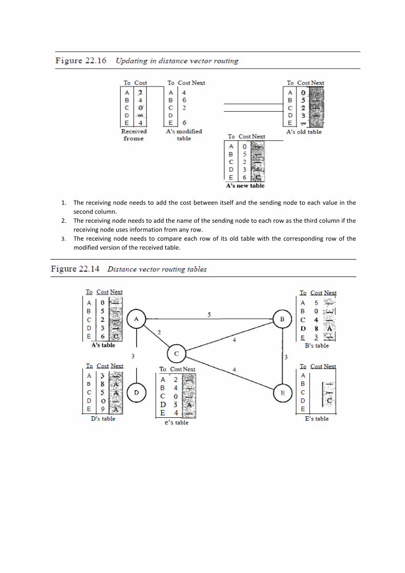
1. The receiving node needs to add the cost between itself and the sending node to each value in the
second column.
2. The receiving node needs to add the name of the sending node to each row as the third column if the
receiving node uses information from any row.
3. The receiving node needs to compare each row of its old table with the corresponding row of the
modified version of the received table.

Link State Routing:
Node A knows that it is connected to node B with metric 5, to node C with metric 2, and to node D with
metric 3. Node C knows that it is connected to node A with metric 2, to node B with metric 4, and to node E with
metric 4. Node D knows that it is connected only to node A with metric 3. And so on.
Building Routing Tables
In link state routing, four sets of actions are required to ensure that each node has the routing table.
1. Creation of the states of the links by each node, called the link state packet (LSP).
2. Dissemination of LSPs to every other router, called flooding, in an efficient and reliable way.
3. Formation of a shortest path tree for each node.
4. Calculation of a routing table based on the shortest path tree.
Creation of Link State Packet (LSP) A link state packet can carry a large amount of information. For the
moment, however, we assume that it carries a minimum amount of data: the node identity, the list of links, a
sequence number, and age. The first two, node identity and the list of links, are needed to make the topology.
The third, sequence number, facilitates flooding and distinguishes new LSPs from old ones. The fourth, age,
prevents old LSPs from remaining in the domain for a long time. LSPs are generated on two occasions:
1. When there is a change in the topology of the domain.
2. On a periodic basis.
Flooding of LSPs After a node has prepared an LSP, it must be disseminated to all other nodes, not only to
its neighbors. The process is called flooding and based on the following:
1. The creating node sends a copy of the LSP out of each interface.
2. A node that receives an LSP compares it with the copy it may already have. If the newly arrived LSP is
older than the one it has (found by checking the sequence number), it discards the LSP. If it is newer,
the node does the following:
a) It discards the old LSP and keeps the new one.
b) It sends a copy of it out of each interface except the one from which the packet arrived. This
guarantees that flooding stops somewhere in the domain (where a node has only one interface).
Formation of Shortest Path Tree: Dijkstra Algorithm After receiving all LSPs, each node will have a copy
of the whole topology. However, the topology is not sufficient to find the shortest path to every other node; a
shortest path tree is needed.
The Dijkstra algorithm creates a shortest path tree from a graph. The algorithm divides the nodes into
two sets: tentative and permanent. It finds the neighbors of a current node, makes them tentative, examines
them, and if they pass the criteria, makes them permanent.

Permanent list: empty Tentative list: A(O)

Permanent list: A(O) Tentative list: B(5), C(2), D(3)
Permanent list: A(O), e(2) Tentative list: B(5), 0(3), E(6)
Permanent list: A(O), C(2), 0(3) Tentative list: B(5), E(6)
Permanent list: A(O), B(5), C(2), 0(3) Tentative list: E(6)
Permanent list: A(O), B(5), C(2), D(3), E(6) Tentative list: empty
Calculation of Routing Table from Shortest Path Tree Each node uses the shortest path tree protocol to
construct its routing table. The routing table shows the cost of reaching each node from the root. Table 22.2
shows the routing table for node A.
Unicast vs. Multicast:
Unicast Multicast
One to One communication One to many communication
Packets starts from the source and passes
through routers to reach the destination
Packets starts from the source and passes
through routers to reach a group of destination
Source and destination are unicast addresses Source address is unicast and destination
address is group address
Routers forwards the received packets through
only one of its interfaces
Routers may forward the received packets
through several of its interfaces
Broadcast:
1. One to all communication
2. One source and all the other hosts are the destination
3. Internet doesn’t support broadcasting because of huge amount of traffic and bandwidth
4. It is less secure as compared to unicast and multicast
Unit – V (cont.)
Leaky Bucket
If a bucket has a small hole at the bottom, the water leaks from the bucket at a constant rate as long as
there is water in the bucket. The rate at which the water leaks does not depend on the rate at which the water
is input to the bucket unless the bucket is empty. The input rate can vary, but the output rate remains constant.

Similarly, in networking, a technique called leaky bucket can smooth out bursty traffic. Bursty chunks are stored
in the bucket and sent out at an average rate.
In the figure, we assume that the network has committed a bandwidth of 3 Mbps for a host. The use of
the leaky bucket shapes the input traffic to make it conform to this commitment. In Figure 24.19 the host sends
a burst of data at a rate of 12 Mbps for 2 s, for a total of 24 Mbits of data. The host is silent for 5 s and then
sends data at a rate of 2 Mbps for 3 s, for a total of 6 Mbits of data. In all, the host has sent 30 Mbits of data in
lOs. The leaky bucket smooths the traffic by sending out data at a rate of 3 Mbps during the same 10 s. Without
the leaky bucket, the beginning burst may have hurt the network by consuming more bandwidth than is set
aside for this host. We can also see that the leaky bucket may prevent congestion. As an analogy, consider the
freeway during rush hour (bursty traffic). If, instead, commuters could stagger their working hours, congestion
on our freeways could be avoided.
The following is an algorithm for variable-length packets:
1. Initialize a counter to n at the tick of the clock.
2. If n is greater than the size of the packet, send the packet and decrement the counter by the packet size.
Repeat this step until n is smaller than the packet size.
3. Reset the counter and go to step 1.
A leaky bucket algorithm shapes bursty traffic into fixed-rate traffic by averaging the data rate. It may
drop the packets if the bucket is full.
Token Bucket
The leaky bucket is very restrictive. It does not credit an idle host. For example, if a host is not sending
for a while, its bucket becomes empty. Now if the host has bursty data, the leaky bucket allows only an average
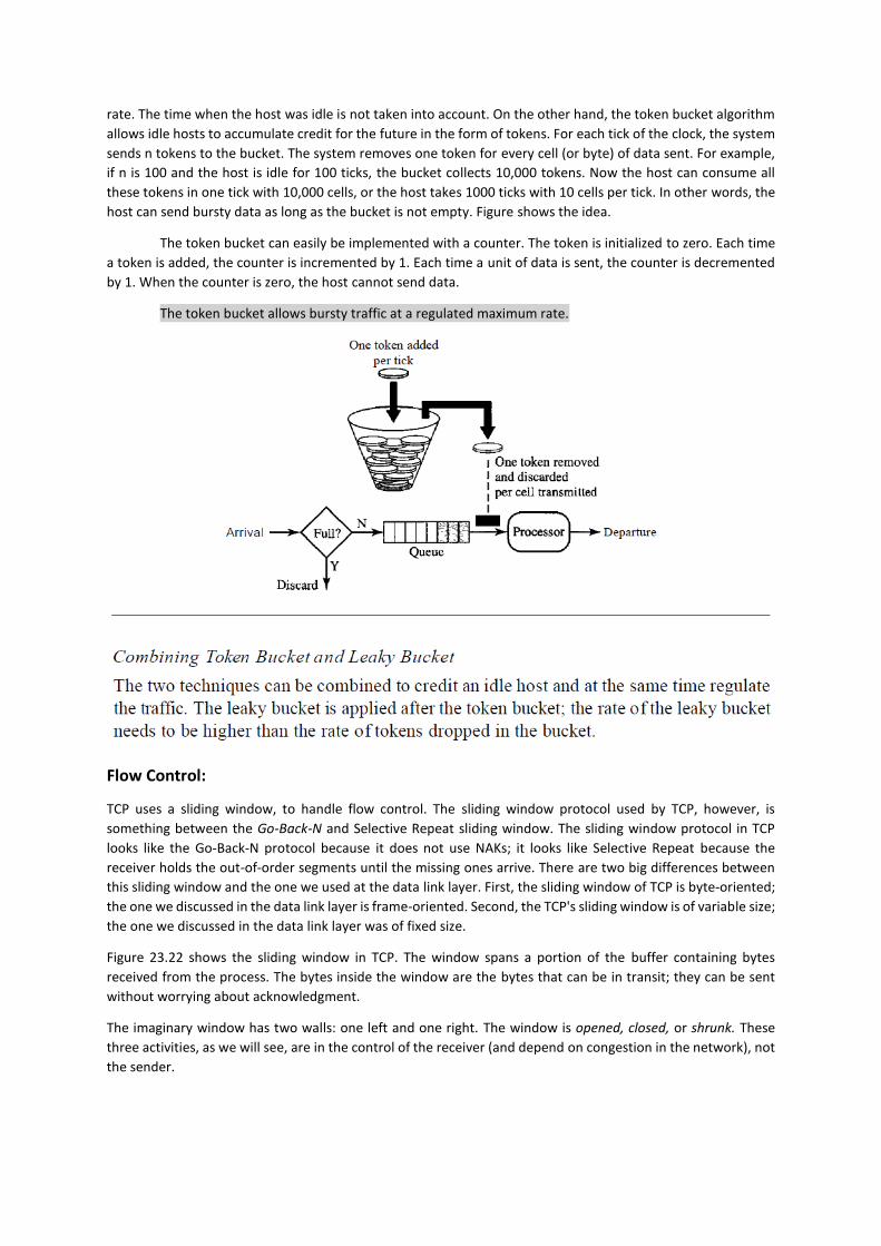
rate. The time when the host was idle is not taken into account. On the other hand, the token bucket algorithm
allows idle hosts to accumulate credit for the future in the form of tokens. For each tick of the clock, the system
sends n tokens to the bucket. The system removes one token for every cell (or byte) of data sent. For example,
if n is 100 and the host is idle for 100 ticks, the bucket collects 10,000 tokens. Now the host can consume all
these tokens in one tick with 10,000 cells, or the host takes 1000 ticks with 10 cells per tick. In other words, the
host can send bursty data as long as the bucket is not empty. Figure shows the idea.
The token bucket can easily be implemented with a counter. The token is initialized to zero. Each time
a token is added, the counter is incremented by 1. Each time a unit of data is sent, the counter is decremented
by 1. When the counter is zero, the host cannot send data.
The token bucket allows bursty traffic at a regulated maximum rate.
Flow Control:
TCP uses a sliding window, to handle flow control. The sliding window protocol used by TCP, however, is
something between the Go-Back-N and Selective Repeat sliding window. The sliding window protocol in TCP
looks like the Go-Back-N protocol because it does not use NAKs; it looks like Selective Repeat because the
receiver holds the out-of-order segments until the missing ones arrive. There are two big differences between
this sliding window and the one we used at the data link layer. First, the sliding window of TCP is byte-oriented;
the one we discussed in the data link layer is frame-oriented. Second, the TCP's sliding window is of variable size;
the one we discussed in the data link layer was of fixed size.
Figure 23.22 shows the sliding window in TCP. The window spans a portion of the buffer containing bytes
received from the process. The bytes inside the window are the bytes that can be in transit; they can be sent
without worrying about acknowledgment.
The imaginary window has two walls: one left and one right. The window is opened, closed, or shrunk. These
three activities, as we will see, are in the control of the receiver (and depend on congestion in the network), not
the sender.

The sender must obey the commands of the receiver in this matter. Opening a window means moving the right
wall to the right. This allows more new bytes in the buffer that are eligible for sending. Closing the window
means moving the left wall to the right. This means that some bytes have been acknowledged and the sender
need not worry about them anymore. Shrinking the window means moving the right wall to the left.
The size of the window at one end is determined by the lesser of two values: receiver window (rwnd) or
congestion window (cwnd). The receiver window is the value advertised by the opposite end in a segment
containing acknowledgment. It is the number of bytes the other end can accept before its buffer overflows and
data are discarded. The congestion window is a value determined by the network to avoid congestion.