Unit 8 : ROBOTICS INTRODUCTION - Book Spar | … in Robot Studies Definition An industrial robot is...
29
Unit 8 : ROBOTICS INTRODUCTION Robots are devices that are programmed to move parts, or to do work with a tool. Robotics is a multidisciplinary engineering field dedicated to the development of autonomous devices, including manipulators and mobile vehicles. The Origins of Robots Year 1250 Bishop Albertus Magnus holds banquet at which guests were served by metal attendants. Upon seeing this, Saint Thomas Aquinas smashed the attendants to bits and called the bishop a sorcerer. Year 1640 Descartes builds a female automaton which he calls “Ma fille Francine.” She accompanied Descartes on a voyage and was thrown overboard by the captain, who thought she was the work of Satan. Year 1738 Jacques de Vaucanson builds a mechanical duck quack, bathe, drink water, eat grain, digest it and void it. Whereabouts of the duck are unknown today. Year 1805 Doll, made by Maillardet, that wrote in either French or English and could draw landscapes Year 1923 Karel Capek coins the term robot in his play Rossum’s Universal Robots (R.U.R). Robot comes from the Czech word robota , which means “servitude, forced labor.” Year 1940 Sparko, the Westinghouse dog, was developed which used both mechanical and electrical components. www.bookspar.com | VTU NOTES | QUESTION PAPERS | NEWS | RESULTS | FORUMS www.bookspar.com | VTU NOTES | QUESTION PAPERS | NEWS | RESULTS | FORUMS www.bookspar.com | VTU NOTES | QUESTION PAPERS | NEWS | RESULTS | FORUMS www.bookspar.com | VTU NOTES | QUESTION PAPERS | NEWS | RESULTS | FORUMS
Transcript of Unit 8 : ROBOTICS INTRODUCTION - Book Spar | … in Robot Studies Definition An industrial robot is...

Unit 8 :
ROBOTICS
INTRODUCTION
Robots are devices that are programmed to move parts, or to do work with a tool. Robotics is
a multidisciplinary engineering field dedicated to the development of autonomous devices,
including manipulators and mobile vehicles.
The Origins of Robots
Year 1250
Bishop Albertus Magnus holds banquet at which guests were served by metal
attendants. Upon seeing this, Saint Thomas Aquinas smashed the attendants to bits and called
the bishop a sorcerer.
Year 1640
Descartes builds a female automaton which he calls “Ma fille Francine.” She accompanied
Descartes on a voyage and was thrown overboard by the captain, who thought she was the
work of Satan.
Year 1738
Jacques de Vaucanson builds a mechanical duck quack, bathe, drink water, eat grain, digest it
and void it. Whereabouts of the duck are unknown today.
Year 1805
Doll, made by Maillardet, that wrote in either French or English and could draw landscapes
Year 1923
Karel Capek coins the term robot in his play Rossum’s Universal Robots (R.U.R). Robot
comes from the Czech word robota , which means “servitude, forced labor.”
Year 1940
Sparko, the Westinghouse dog, was developed which used both mechanical and electrical
components.
www.bookspar.com | VTU NOTES | QUESTION PAPERS | NEWS | RESULTS | FORUMS
www.bookspar.com | VTU NOTES | QUESTION PAPERS | NEWS | RESULTS | FORUMS
www.bookspar.com | VTU NOTES | QUESTION PAPERS | NEWS | RESULTS | FORUMS
www.bookspar.com | VTU NOTES | QUESTION PAPERS | NEWS | RESULTS | FORUMS
Year 1950’s to 1960’s
Computer technology advances and control machinery is developed. Questions Arise: Is the
computer an immobile robot? Industrial Robots created. Robotic Industries Association states
that an “industrial robot is a re-programmable, multifunctional manipulator designed to
move materials, parts, tools, or specialized devices through variable programmed motions to
perform a variety of tasks”
Year 1956
Researchers aim to combine “perceptual and problem-solving capabilities,” using computers,
cameras, and touch sensors. The idea is to study the types of intelligent actions these robots
are capable of. A new discipline is born: A.I.
Year 1960
Shakey is made at Stanford Research Institute International. It contained a television
camera, range finder, on-board logic, bump sensors, camera control unit, and an antenna for a
radio link. Shakey was controlled by a computer in a different room.
The first industrial robot: UNIMATE Year 1954
The first programmable robot is designed by George Devol, who coins the term Universal
Automation. He later shortens this to Unimation, which becomes the name of the first robot
company (1962).
Year 1978
The Puma (Programmable Universal Machine for Assembly) robot is developed by
Unimation with a General Motors design support
Year 1980s
The robot industry enters a phase of rapid growth. Many institutions introduce programs and
courses in robotics. Robotics courses are spread across mechanical engineering, electrical
engineering, and computer science departments.
Year 1995-present
Emerging applications in small robotics and mobile robots drive a second
growth of start-up companies and research
2003
NASA’s Mars Exploration Rovers will launch toward Mars in search of answers about the
history of water on Mars
www.bookspar.com | VTU NOTES | QUESTION PAPERS | NEWS | RESULTS | FORUMS
www.bookspar.com | VTU NOTES | QUESTION PAPERS | NEWS | RESULTS | FORUMS
www.bookspar.com | VTU NOTES | QUESTION PAPERS | NEWS | RESULTS | FORUMS
www.bookspar.com | VTU NOTES | QUESTION PAPERS | NEWS | RESULTS | FORUMS

Categories in Robot Studies
Definition
An industrial robot is a general purpose, programmable machine possessing certain
anthropomorphic characteristics. The most typical anthropomorphic or human like,
characteristics of a robot is its arm. This arm, together with the robots capacity to be
programmed, make it ideally suited to a variety of production tasks, including machine
loading, spot welding, spray painting and assembly. The robot can be programmed to perform
sequence of mechanical motions, and it can repeat that motion sequence over the over until
programmed to perform some other job.
An industrial robot is a general purpose programmable machine that possesses certain
anthropomorphic features
• The most apparent anthropomorphic feature of an industrial robot is its mechanical
arm, or manipulator
• Robots can perform a variety of tasks such as loading and unloading machine tools,
spot welding automobile bodies, and spray painting
• Robots are typically used as substitutes for human workers in these tasks
An industrial robot is a programmable, multi-functional manipulator designed to move
materials, parts, tools, or special devices through variable programmed motions for the
performance of a variety of tasks.
An industrial robot consists of a mechanical manipulator and a controller to move it and
perform other related functions
• The mechanical manipulator consists of joints and links to position and orient the end
of the manipulator relative to its base
• The controller operates the joints in a coordinated fashion to execute a programmed
work cycle
• A robot joint is similar to a human body joint It provides relative movement between
two parts of the body
• Typical industrial robots have five or six joints, Manipulator joints: classified as linear
or rotating
www.bookspar.com | VTU NOTES | QUESTION PAPERS | NEWS | RESULTS | FORUMS
www.bookspar.com | VTU NOTES | QUESTION PAPERS | NEWS | RESULTS | FORUMS
www.bookspar.com | VTU NOTES | QUESTION PAPERS | NEWS | RESULTS | FORUMS
www.bookspar.com | VTU NOTES | QUESTION PAPERS | NEWS | RESULTS | FORUMS
How are robots used?
• Industrial robots do tasks that are hazardous or menial.
• Exploratory robots explore environments that are inhospitable to humans such as
space, military targets or areas of search and rescue operations.
• Assistive robots help handicapped individuals by assisting with daily tasks including
wheelchair navigation and feeding.
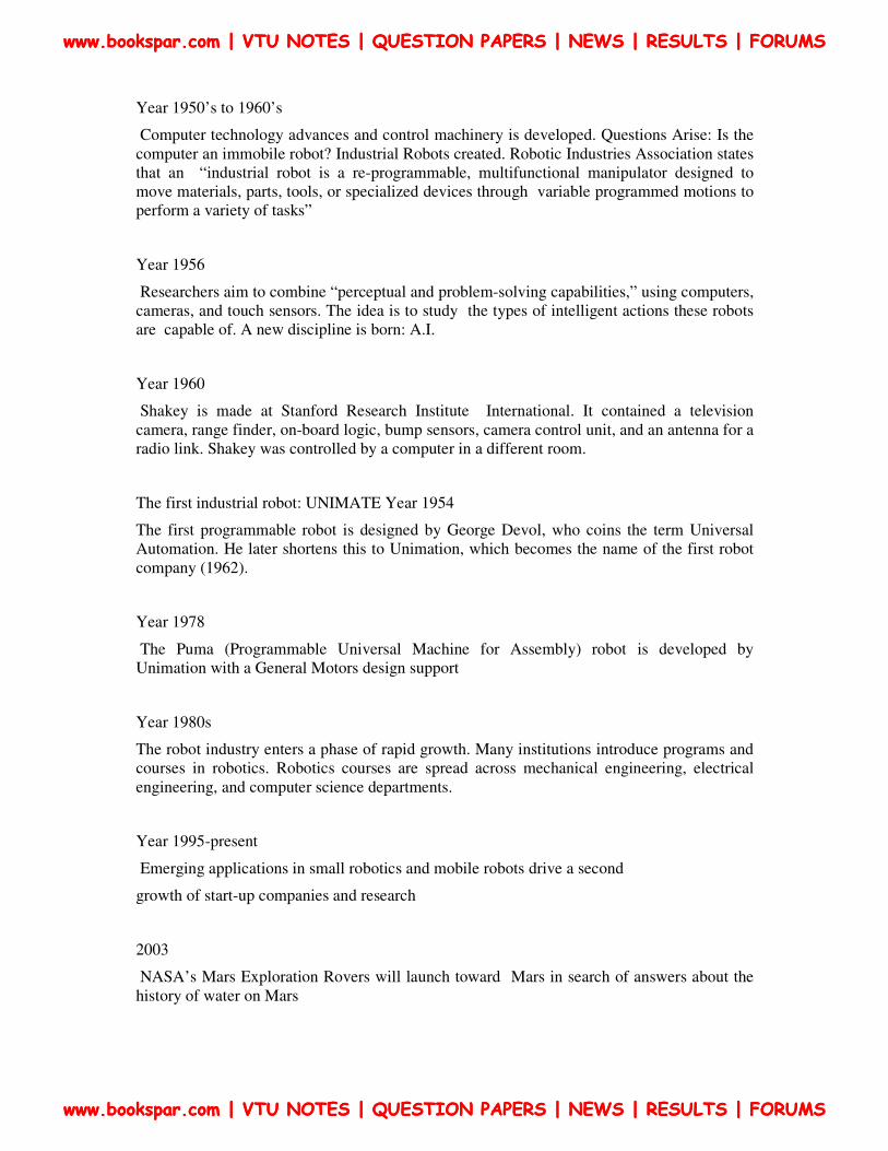
ROBOT ANATOMY
Translational motion
Linear joint (type L)
Orthogonal joint (type O)
Rotary motion
Rotational joint (type R)
Twisting joint (type T)
Revolving joint (type V)
Types of joints
(a) Linear joint (type L joint) , (b) orthogonal joint (type O joint ) (c) Rotational joint
(type R joint )
www.bookspar.com | VTU NOTES | QUESTION PAPERS | NEWS | RESULTS | FORUMS
www.bookspar.com | VTU NOTES | QUESTION PAPERS | NEWS | RESULTS | FORUMS
www.bookspar.com | VTU NOTES | QUESTION PAPERS | NEWS | RESULTS | FORUMS
www.bookspar.com | VTU NOTES | QUESTION PAPERS | NEWS | RESULTS | FORUMS
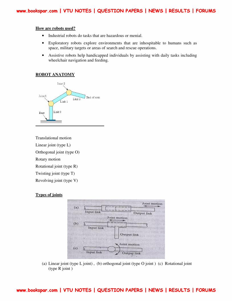
(d) Twisting joint ( type T joint) (e) revolving joint (type V joint)
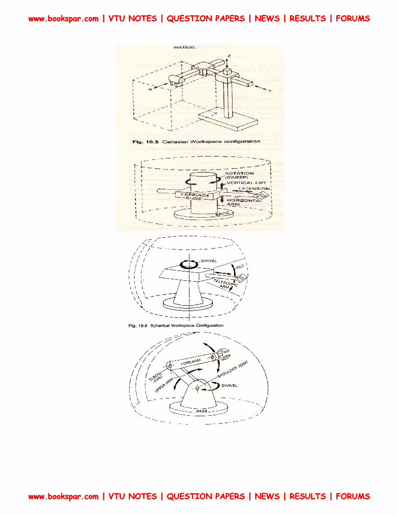
Robot Physical Configuration
Industrial robots come in a variety of shapes and sizes. They are capable of various arm
manipulations and they possess different motion systems.
Classification based on Physical configurations
Four basic configurations are identified with most of the commercially available industrial
robots
1. Cartesian configuration: A robot which is constructed around this configuration consists
of three orthogonal slides, as shown in fig. the three slides are parallel to the x, y, and z axes
of the Cartesian coordinate system. By appropriate movements of these slides, the robot is
capable of moving its arm at any point within its three dimensional rectangularly spaced work
space.
2. Cylindrical configuration: in this configuration, the robot body is a vertical column that
swivels about a vertical axis. The arm consists of several orthogonal slides which allow the
arm to be moved up or down and in and out with respect to the body. This is illustrated
schematically in figure.
3. Polar configuration: this configuration also goes by the name “spherical coordinate”
because the workspace within which it can move its arm is a partial sphere as shown in
figure. The robot has a rotary base and a pivot that can be used to raise and lower a
telescoping arm.
4. Jointed-arm configuration: is combination of cylindrical and articulated configurations.
This is similar in appearance to the human arm, as shown in fig. the arm consists of several
www.bookspar.com | VTU NOTES | QUESTION PAPERS | NEWS | RESULTS | FORUMS
www.bookspar.com | VTU NOTES | QUESTION PAPERS | NEWS | RESULTS | FORUMS
www.bookspar.com | VTU NOTES | QUESTION PAPERS | NEWS | RESULTS | FORUMS
www.bookspar.com | VTU NOTES | QUESTION PAPERS | NEWS | RESULTS | FORUMS

straight members connected by joints which are analogous to the human shoulder, elbow, and
wrist. The robot arm is mounted to a base which can be rotated to provide the robot with the
capacity to work within a quasi-spherical space.
www.bookspar.com | VTU NOTES | QUESTION PAPERS | NEWS | RESULTS | FORUMS
www.bookspar.com | VTU NOTES | QUESTION PAPERS | NEWS | RESULTS | FORUMS
www.bookspar.com | VTU NOTES | QUESTION PAPERS | NEWS | RESULTS | FORUMS
www.bookspar.com | VTU NOTES | QUESTION PAPERS | NEWS | RESULTS | FORUMS

Basic Robot Motions
Whatever the configuration, the purpose of the robot is to perform a useful task. To
accomplish the task, an end effector, or hand, is attached to the end of the robots arm. It is the
end effector which adapts the general purpose robot to a particular task. To do the task, the
robot arm must be capable of moving the end effectors through a sequence of motions and
positions.
There are six basic motions or degrees of freedom, which provide the robot with the
capability to move the end effectors through the required sequences of motions. These six
degree of freedom are intended to emulate the versatility of movement possessed by the
human arm. Not all robots are equipped with the ability to move in all sex degrees. The six
basic motions consist of three arm and body motions and three wrist motions.
Arm and body motions
1. Vertical traverse: Up and down motion of the arm, caused by pivoting the entire arm
about a horizontal axis or moving the arm along a vertical slide.
2. Radial traverse: extension and retraction of the arm (in and out movement)
3. Rotational traverse: rotation about the vertical axis (right or left swivel of the robot
arm)
www.bookspar.com | VTU NOTES | QUESTION PAPERS | NEWS | RESULTS | FORUMS
www.bookspar.com | VTU NOTES | QUESTION PAPERS | NEWS | RESULTS | FORUMS
www.bookspar.com | VTU NOTES | QUESTION PAPERS | NEWS | RESULTS | FORUMS
www.bookspar.com | VTU NOTES | QUESTION PAPERS | NEWS | RESULTS | FORUMS

Wrist Motion
• Wrist swivel: Rotation of the wrist
• Wrist bend: Up or down movement of the wrist, this also involves rotation
movement.
• Wrist yaw: Right or left swivel of the wrist.
Advantages and disadvantages of 5 types of robots
Configurations Advantages Disadvantages
Cartesian coordinates 3 linear axes, easy to visualize,rigid
structure ,easy programming
Can only reach front of itself,
requirse long room space.
Cylindrical
coordinates
2 linear axes +1 rotating can reach all
around itself ,reach and height axes rigid
,rotational axis easy to seal
Can’t reach above itself, base
rotation axis as less rigid, linear axis
is hard to seal.
SCARA coordinates 1 linear + 2 rotational axes is rigid, large
work space area for floor space
2 ways to reach point ,difficult to
program offline, highly complex
arm
Spherical coordinates 1 linear + 2 rotational axes , long
horizontal reach
Can’t reach around obstacles .short
vertical length
Revolve coordinates 3 rotational axes can reach above or
below obstacles.
Difficult to program off-line , most
complex manipulator
www.bookspar.com | VTU NOTES | QUESTION PAPERS | NEWS | RESULTS | FORUMS
www.bookspar.com | VTU NOTES | QUESTION PAPERS | NEWS | RESULTS | FORUMS
www.bookspar.com | VTU NOTES | QUESTION PAPERS | NEWS | RESULTS | FORUMS
www.bookspar.com | VTU NOTES | QUESTION PAPERS | NEWS | RESULTS | FORUMS

Motion system
1. Point-to-point (PTP) control robot: is capable of moving from one point to another
point. The locations are recorded in the control memory. PTP robots do not control
the path to get from one point to the next point. Common applications include
component insertion, spot welding, hole drilling, machine loading and unloading, and
crude assembly operations.
2. Continuous-path (CP) control robot: with CP control, the robot can stop at any
specified point along the controlled path. All the points along the path must be stored
explicitly in the robot’s control memory. Typical applications include spray painting,
finishing, gluing, and arc welding operations.
3. Controlled-path robot: the control equipment can generate paths of different
geometry such as straight lines, circles, and interpolated curves with a high degree of
accuracy. All controlled-path robots have a servo capability to correct their path.
Technical Features Of An Industrial Robot
The technical features of an industrial robot determine its efficiency and effectiveness at
performing a given task. The following are some of the most important among these technical
features.
Degree of Freedom (D.O.F) - Each joint on the robot introduces a degree of freedom. Each
dof can be a slider, rotary, or other type of actuator. Robots typically have 5 or 6 degrees of
freedom. 3 of the degrees of freedom allow positioning in 3D space, while the other 2or 3 are
used for orientation of the end effector. 6 degrees of freedom are enough to allow the robot to
reach all positions and orientations in 3D space. 5 D.O.F requires a restriction to 2D space, or
else it limits orientations. 5 D.O.F robots are commonly used for handling tools such as arc
welders.
Work Volume/Workspace - The robot tends to have a fixed and limited geometry. The
work envelope is the boundary of positions in space that the robot can reach. For a Cartesian
robot (like an overhead crane) the workspace might be a square, for more sophisticated robots
the workspace might be a shape that looks like a ‘clump of intersecting bubbles’.
www.bookspar.com | VTU NOTES | QUESTION PAPERS | NEWS | RESULTS | FORUMS
www.bookspar.com | VTU NOTES | QUESTION PAPERS | NEWS | RESULTS | FORUMS
www.bookspar.com | VTU NOTES | QUESTION PAPERS | NEWS | RESULTS | FORUMS
www.bookspar.com | VTU NOTES | QUESTION PAPERS | NEWS | RESULTS | FORUMS
www.bookspar.com | VTU NOTES | QUESTION PAPERS | NEWS | RESULTS | FORUMS
www.bookspar.com | VTU NOTES | QUESTION PAPERS | NEWS | RESULTS | FORUMS
www.bookspar.com | VTU NOTES | QUESTION PAPERS | NEWS | RESULTS | FORUMS
www.bookspar.com | VTU NOTES | QUESTION PAPERS | NEWS | RESULTS | FORUMS

Precision Movement
The precision with which the robot can move the end of its wrist is a critical consideration in
most applications. In robotics, precision of movement is a complex issue, and we will
describe it as consisting of three attributes:
1. Control resolution
2. Accuracy
3. Repeatability
Control Resolution - This is the smallest change that can be measured by the feedback
sensors, or caused by the actuators, whichever is larger. If a rotary joint has an encoder that
measures every 0.01 degree of rotation, and a direct drive servo motor is used to drive the
joint, with a resolution of 0.5 degrees, then the control resolution is about 0.5 degrees (the
worst case can be 0.5+0.01).
Accuracy - This is determined by the resolution of the workspace. If the robot is commanded
to travel to a point in space, it will often be off by some amount, the maximum distance
should be considered the accuracy.
Repeatability - The robot mechanism will have some natural variance in it. This means that
when the robot is repeatedly instructed to return to the same point, it will not always stop at
the same position.
www.bookspar.com | VTU NOTES | QUESTION PAPERS | NEWS | RESULTS | FORUMS
www.bookspar.com | VTU NOTES | QUESTION PAPERS | NEWS | RESULTS | FORUMS
www.bookspar.com | VTU NOTES | QUESTION PAPERS | NEWS | RESULTS | FORUMS
www.bookspar.com | VTU NOTES | QUESTION PAPERS | NEWS | RESULTS | FORUMS

A portion of a linear positioning system axis, with showing control resolution, accuracy, and
repeatability
Speed - refers either to the maximum velocity that is achievable by the TCP, or by individual
joints. This number is not accurate in most robots, and will vary over the workspace as the
geometry of the robot changes.
Weight Carrying Capacity (Payload) - The payload indicates the maximum mass the robot
can lift before either failure of the robots, or dramatic loss of accuracy. It is possible to
exceed the maximum payload, and still have the robot operate, but this is not advised. When
www.bookspar.com | VTU NOTES | QUESTION PAPERS | NEWS | RESULTS | FORUMS
www.bookspar.com | VTU NOTES | QUESTION PAPERS | NEWS | RESULTS | FORUMS
www.bookspar.com | VTU NOTES | QUESTION PAPERS | NEWS | RESULTS | FORUMS
www.bookspar.com | VTU NOTES | QUESTION PAPERS | NEWS | RESULTS | FORUMS

the robot is accelerating fast, the payload should be less than the maximum mass. This is
affected by the ability to firmly grip the part, as well as the robot structure, and the actuators.
The end of arm tooling should be considered part of the payload.
Types Of Drive Systems
There are three basic drive system used in commercially available robots:
1. Hydraulic drive: gives a robot great speed and strength. These systems can be designed to
actuate linear or rotational joints. The main disadvantage of a hydraulic system is that it
occupies floor space in addition to that required by the robot.
2. Electric drive: compared with a hydraulic system, an electric system provides a robot with
less speed and strength. Accordingly, electric drive systems are adopted for smaller robots.
However, robots supported by electric drive systems are more accurate, exhibit better
repeatability, and are cleaner to use.
3. Pneumatic drive: are generally used for smaller robots. These robots, with fewer degrees
of freedom, carry out simple pick-and-place material handling operations.
www.bookspar.com | VTU NOTES | QUESTION PAPERS | NEWS | RESULTS | FORUMS
www.bookspar.com | VTU NOTES | QUESTION PAPERS | NEWS | RESULTS | FORUMS
www.bookspar.com | VTU NOTES | QUESTION PAPERS | NEWS | RESULTS | FORUMS
www.bookspar.com | VTU NOTES | QUESTION PAPERS | NEWS | RESULTS | FORUMS

PROGRAMMING THE ROBOT
There are various methods which robots can be programmed to perform a given work cycle.
We divide this programming method into four categories.
1. Manual method
2. Walkthrough method
3. Lead through method
4. Off-line programming
Manual method:
This method is not really programming in the conventional sense of the world. It is more like
setting up a machine rather than programming. It is the procedure used for the simpler robots
and involves setting mechanical stops, cams, switches or relays in the robots control unit. For
these low technology robots used for short work cycles (e.g., pick and place operations), the
manual programming method is adequate.
Walkthrough method:
In this method the programmer manually moves the robots arm and hand through the motion
sequence of the work cycle. Each movement is recorded into memory for subsequent
playback during production. The speed with which the movements are performed can usually
be controlled independently so that the programmer does not have to worry about the cycle
time during the walk through. The main concern is getting the position sequence correct. The
walk through method would be appropriate for spray painting and arc welding.
Lead through method:
The lead through method makes use of a teach pendant to power drive the robot through its
motion sequence. The teach pendant is usually a small hand held device with switches and
dials to control the robots physical movements. Each motion is recorded into memory for
future playback during work cycle. The lead through method is very popular among robot
programming methods because of its ease and convenience.
www.bookspar.com | VTU NOTES | QUESTION PAPERS | NEWS | RESULTS | FORUMS
www.bookspar.com | VTU NOTES | QUESTION PAPERS | NEWS | RESULTS | FORUMS
www.bookspar.com | VTU NOTES | QUESTION PAPERS | NEWS | RESULTS | FORUMS
www.bookspar.com | VTU NOTES | QUESTION PAPERS | NEWS | RESULTS | FORUMS
On-Line/Lead -Through programming
Advantage:
� Easy
� No special programming skills or training
Disadvantages:
� not practical for large or heavy robots
� High accuracy and straight-line movements are difficult to achieve, as
are any other kind of geometrically defined trajectory, such as circular
arcs, etc.
� difficult to edit out unwanted operator moves
� difficult to incorporate external sensor data
� Synchronization with other machines or equipment in the work cell is
difficult
� A large amount of memory is required
Off- line programming:
This method involves the preparation of the robot program off-line, in a manner similar to
NC part programming. Off-line robot programming is typically accomplished on a computer
terminal. After the program has been prepared, it is entered in to the robot memory for use
during the work cycle. The advantaged of off-line robot programming is that the production
time of the robot is not lost to delay in teaching the robot a new task. Programming off-line
can be done while the robot is still in production on the preceding job. This means higher
utilization of the robot and the equipment with which it operates.
Another benefit associated with off-line programming is the prospect of integrating the robot
into the factory CAD/CAM data base and information system.
Robot Programming Languages
Non computer controlled robots do not require programming language. They are programmed
by the walkthrough or lead through methods while the simpler robots are programmed by
manual methods. With the introduction of computer control for robots came the opportunity
and the need to develop a computer oriented robot programming language.
The VALTM
Language
• The VAL language was developed for PUMA robot
• VAL stands for Victors Assembly Language
www.bookspar.com | VTU NOTES | QUESTION PAPERS | NEWS | RESULTS | FORUMS
www.bookspar.com | VTU NOTES | QUESTION PAPERS | NEWS | RESULTS | FORUMS
www.bookspar.com | VTU NOTES | QUESTION PAPERS | NEWS | RESULTS | FORUMS
www.bookspar.com | VTU NOTES | QUESTION PAPERS | NEWS | RESULTS | FORUMS

• It is basically off-line language in which program defining the motion sequence is can
be developed off-line but various point location used in the work cycle are defined by
lead through.
• VAL statements are divided into two categories a) Monitoring command b)
Programming instructions.
• Monitor command are set of administrative instructions that direct the operation of the
robot system. Some of the functions of Monitor commands are
Preparing the system for the user to write programs for PUMA
Defining points in space
Commanding the PUMA to execute a program
Listing program on the CRT
• Examples for monitor commands are: EDIT, EXECUTE, SPEED, HERE etc.
• Program instructions are a set of statements used to write robot programs. One
statement usually corresponds to one movement of the robots arm or wrist.
• Example for program instructions are Move to point, move to a point in a straight line
motion, open gripper, close gripper. (MOVE, MOVES, APPRO, APPROS, DEPART,
OPENI, CLOSEI, AND EXIT)
The MCL Language
• MCL stands for Machine Control Language developed by Douglas.
• The language is based on the APT and NC language. Designed control complete
manufacturing cell.
• MCL is enhancement of APT which possesses additional options and features needed
to do off-line programming of robotic work cell.
• Additional vocabulary words were developed to provide the supplementary
capabilities intended to be covered by the MCL. These capability include Vision,
Inspection and Control of signals
• MCL also permits the user to define MACROS like statement that would be
convenient to use for specialized applications.
• MCL program is needed to compile to produce CLFILE.
• Some commands of MCL programming languages are DEVICE, SEND, RECEIV,
WORKPT, ABORT, TASK, REGION, LOCATE etc.
Textual Statements
Language statements taken from commercially available robot languages
1 The basic motion statement is:
MOVE P1
Commands the robot to move from its current position to a position and orientation defined
by the variable name P1.The point p1 must be defined.
www.bookspar.com | VTU NOTES | QUESTION PAPERS | NEWS | RESULTS | FORUMS
www.bookspar.com | VTU NOTES | QUESTION PAPERS | NEWS | RESULTS | FORUMS
www.bookspar.com | VTU NOTES | QUESTION PAPERS | NEWS | RESULTS | FORUMS
www.bookspar.com | VTU NOTES | QUESTION PAPERS | NEWS | RESULTS | FORUMS

The most convenient method way to define P1 is to use either powered lead through or
manual leads through to place the robot at the desired point and record that point into the
memory.
HERE P1
OR
LEARN P1
Are used in the lead through procedure to indicate the variable name for the point
What is recorded into the robot’s control memory is the set of joint positions or coordinates
used by the controller to define the point.
For ex, (236,157,63,0,0,0)
The first values give joint positions of the body and arm and the last three values(0,0,0)
define the wrist joint positions.
MOVES P1
Denotes a move that is to be made using straight line interpolation. The suffix‘s’ designates a
straight line motion.
DMOVE (4,125)
Suppose the robot is presently at a point defined by joint coordinates(236,157,63,0,0,0) and it
is desired to move joint 4from 0 to 125. The above statement can be used to accomplish this
move. DMOVE represents a delta move.
Approach and depart statements are useful in material handling operations.
APPROACH P1, 40 MM
MOVE P1
(Command to actuate the gripper)
DEPART 40 MM
The destination is point p1 but the approach command moves the gripper to a safe
distance(40mm) above the point.
Move statement permits the gripper to be moved directly to the part for grasping.
A path in a robot program is a series of points connected together in a single move. A path is
given a variable name
DEFINE PATH123=PATH(P1,P2,P3)
A move statement is used to drive the robot through the path.
MOVE PATH123
SPEED 75 the manipulator should operate at 75% of the initially commanded velocity. The
initial speed is given in a command that precedes the execution of the robot program.
For example,
SPEED 0.5 MPS
www.bookspar.com | VTU NOTES | QUESTION PAPERS | NEWS | RESULTS | FORUMS
www.bookspar.com | VTU NOTES | QUESTION PAPERS | NEWS | RESULTS | FORUMS
www.bookspar.com | VTU NOTES | QUESTION PAPERS | NEWS | RESULTS | FORUMS
www.bookspar.com | VTU NOTES | QUESTION PAPERS | NEWS | RESULTS | FORUMS

EXECUTE PROGRAM1
Indicates that the program named PROGRAM1 is to be executed by the robot at a speed of
0.5m/sec.
Interlock And Sensor Statements
The two basic interlock commands used for industrial robots are WAIT and SIGNAL. The
wait command is used to implement an input interlock.
For example,
WAIT 20,ON
Would cause program execution to stop at this statement until the input signal coming into
the robot controller at port 20 was in “ON” condition.this might be used in a situation where
the robot needed to wait for the completion of an automatic machine cycle in a loading and
unloading application.
The SIGNAL statement is used to implement an output interlock. This is used to
communicate to some external piece of equipment.
For example,
SIGNAL 20, ON
Would switch on the signal at output port 20, perhaps to actuate the start of of an automatic
machine cycle.
The above interlock commands represent situations where the execution of the statement
appears.
There are other situations where it is desirable for an external device to be continuously
monitored for any change that might occur in the device.
For example,in safety monitoring where a sensor is setup
to detect the presence of humans who might wander into the robot’s work volume.the sensor
reacts to the presence of humans by signaling the robot controller.
REACT 25, SAFESTOP
This command would be written to continuously monitor input port 25 for any changes in the
incoming signal. If and when a change in the signal occurs, regular program execution is
interrupted and the control is transferred to a subroutine called SAFESTOP.This subroutine
would stop the robot from further motion and/or cause some other safety action to be taken.
www.bookspar.com | VTU NOTES | QUESTION PAPERS | NEWS | RESULTS | FORUMS
www.bookspar.com | VTU NOTES | QUESTION PAPERS | NEWS | RESULTS | FORUMS
www.bookspar.com | VTU NOTES | QUESTION PAPERS | NEWS | RESULTS | FORUMS
www.bookspar.com | VTU NOTES | QUESTION PAPERS | NEWS | RESULTS | FORUMS

Commands for controlling the end-effectors
Although end effectors are attached to to the wrist of the manipulator,they are very much like
external devices. Special command are written for controlling the end effector. Basic
commands are
OPEN (fully open)
and
CLOSE (fully close)
For grippers with force sensors that can be regulated through the robot controller, a command
such as ,
CLOSE 2.0 N
Controls the closing of the gripper until a 20.N force is encountered by the grippers.
A similar command would be used to close the gripper to a given opening width is,
CLOSE 25 MM
A special set of statements is often required to control the operation of tool type end effectors
.(such as spot welding guns, arc welding tools, spray painting guns and powered spindles ).
End Effectors
In the terminology of robotics, end effectors can be defined as a device which is attached to
the robots wrist to perform a specific task. The task might be work part handling, spot
welding, spray painting, or any of a great variety of other functions. The possibilities are
limited only by the imagination and ingenuity of the application engineers who design robot
systems. The end effectors are the special purpose tooling which enables the robot to perform
a particular job. It is usually custom engineered for that job, either by the company that owns
the robot or company that sold the robots. Most robot manufacturer has engineered groups
which design and fabricate end effectors or provide advice to their customers on end effectors
design.
For purpose organization, we will divide the various types of end effectors into two
categories: grippers and tools.
1. Grippers: are generally used to grasp and hold an object and place it at a desired
location. Grippers can be classified as
Mechanical grippers
Vacuum or suction cups
Magnetic grippers
Adhesive grippers
Hooks,
Scoops, and so forth.
www.bookspar.com | VTU NOTES | QUESTION PAPERS | NEWS | RESULTS | FORUMS
www.bookspar.com | VTU NOTES | QUESTION PAPERS | NEWS | RESULTS | FORUMS
www.bookspar.com | VTU NOTES | QUESTION PAPERS | NEWS | RESULTS | FORUMS
www.bookspar.com | VTU NOTES | QUESTION PAPERS | NEWS | RESULTS | FORUMS

2. Tools: a robot is required to manipulate a tool to perform an operation on a work part.
Here the tool acts as end-effectors. Spot-welding tools, arc-welding tools, spray-
painting nozzles, and rotating spindles for drilling and grinding are typical examples
of tools used as end-effectors.
Work Cell Control And Interlocks
Work cell control: industrial robots usually work with other things: processing equipment,
work parts, conveyors, tools and perhaps human operators. A means must be provided for
coordinating all of the activities which are going on within the robot workstations. Some of
the activities occur sequentially, while others take place simultaneously to make certain that
the various activities are coordinated and occur in the proper sequence, a device called the
work cell controller is used. The work cell controller usually resides within the robots and has
overall responsibility for regulating the activities of the work cell components.
Functions of work cell controller
1. Controlling the sequence of activities in the work cycles
2. Controlling simultaneous activities
3. Making decisions to proceed based on incoming signals
4. Making logical decisions
5. Performing computations
6. Dealing with exceptional events
7. Performing irregular cycles, such as periodically changing tools
www.bookspar.com | VTU NOTES | QUESTION PAPERS | NEWS | RESULTS | FORUMS
www.bookspar.com | VTU NOTES | QUESTION PAPERS | NEWS | RESULTS | FORUMS
www.bookspar.com | VTU NOTES | QUESTION PAPERS | NEWS | RESULTS | FORUMS
www.bookspar.com | VTU NOTES | QUESTION PAPERS | NEWS | RESULTS | FORUMS

Interlocks
An interlock is the feature of work cell control which prevents the work cycle sequence from
continuing until a certain conditions or set of conditions has been satisfied. In a robotic work
cell, there are two types: outgoing and incoming. The outer going interlock is a signal sent
from the workstation controller to some external machine or device that will cause it to
operate or not to operate for example this would be used to prevent a machine from initiating
its process until it was commanded to process by the work cell controller, an incoming
interlock is a single from some external machine or device to the work controller which
determines whether or not the programmed work cycle sequence will proceed. For example,
this would be used to prevent the work cycle program from continuing until the machine
signaled that it had completed its processing of the work piece.
The use of interlocks provides an important benefit in the control of the work cycle because it
prevents actions from happening when they should not, and it causes actions occur when they
should. Interlocks are needed to help coordinate the activities of the various independent
components in the work cell and to help avert damage of one component by another. In the
planning of interlocks in the robotic work cell, the application engineer must consider both
the normal sequences of the activities that will occur during the work cycle, and the potential
malfunction that might occur. Then these normal activities are linked together by means of
limit switches, pressure switches, photo electric devices, and other system components.
Malfunction that can be anticipated are prevented by means of similar devices.
www.bookspar.com | VTU NOTES | QUESTION PAPERS | NEWS | RESULTS | FORUMS
www.bookspar.com | VTU NOTES | QUESTION PAPERS | NEWS | RESULTS | FORUMS
www.bookspar.com | VTU NOTES | QUESTION PAPERS | NEWS | RESULTS | FORUMS
www.bookspar.com | VTU NOTES | QUESTION PAPERS | NEWS | RESULTS | FORUMS
ROBOTIC SENSORS
For certain robot application, the type of workstation control using interlocks is not
adequate the robot must take on more human like senses and capabilities in order to perform
the task in a satisfactory way these senses and capability includes vision and hand eye
coordination, touch, hearing accordingly we will dived the types of sensors used in robotics
into the following three categories.
1. Vision sensors
2. Tactile and proximity sensors
3. Voice sensors
Vision sensors
This is one of the areas that is receiving a lot of attention in robotics research computerized
visions systems will be an important technology in future automated factories. Robot vision is
made possible by means of video camera a sufficient light source and a computer
programmed to process image data. The camera is mounted either on the robot or in a fixed
position above the robot so that its field of vision includes the robots work volume. The
computer software enables the vision system to sense the presence of an object and its
position and orientation. Vision capability would enable the robot to carry out the following
kinds of operations.
Retrieve parts which are randomly oriented on a conveyor
Recognize particular parts which are intermixed with other objects
Perform assembly operations which require alignment
Tactile and proximity sensor
Tactile sensors provide the robot with the capability to respond to contact forces between
itself and other objects within its work volume. Tactile sensors can be divided into two types:
1. Touch sensors
2. Stress sensors
Touch sensors are used simply to indicate whether contact has been made with an object. A
simple micro switch can serve the purpose of a touch sensor. Stress sensors are used to
measure the magnitude of the contact force. Strain gauge devices are typically employed in
force measuring sensors.
Potential use of robots with tactile sensing capabilities would be in assembly and inspection
operations. In assembly, the robot could perform delicate part alignment and joining
operations. In inspection, touch sensing would be used in gauging operations and dimensional
measuring activities. Proximity sensors are used to sense when one object is close to another
www.bookspar.com | VTU NOTES | QUESTION PAPERS | NEWS | RESULTS | FORUMS
www.bookspar.com | VTU NOTES | QUESTION PAPERS | NEWS | RESULTS | FORUMS
www.bookspar.com | VTU NOTES | QUESTION PAPERS | NEWS | RESULTS | FORUMS
www.bookspar.com | VTU NOTES | QUESTION PAPERS | NEWS | RESULTS | FORUMS

object. On a robot, the proximity sensors would be located n or near the end effectors. This
sensing capability can be engineered by means of optical proximity devices, eddy-current
proximity detectors, magnetic field sensors, or other devices.
In robotics, proximity sensors might be used to indicate the presence or absence of a work
part or other object. They could also be helpful in preventing injury to the robots human
coworkers in the factory.
Voice sensors
Another area of robotics research is voice sensing or voice programming. Voice
programming can be defined as the oral communication of commands to the robot or other
machine. The robot controller is equipped with a speech recognition system which analyzes
the voice input and compares it with a set of stored word patterns when a match is found
between the input and the stored vocabulary word the robot performs some actions which
corresponds to the word. Voice sensors could be useful in robot programming to speed up the
programming procedure just as it does in NC programming. It would also be beneficial in
especially in hazardous working environments for performing unique operations such as
maintenance and repair work. The robot could be placed in hazardous environment and
remotely commanded to perform the repair chores by means of step by step instructions.
Sensors – summary
• Sensors provide a way of simulating “aliveness”
• Sensors give robots environmental awareness
• Sensors provide of means of human protection
• Sensors help robot preserve itself
• Sensors enable goal seeking
• Sensors enable closed-loop interaction
• Sensors make robots interesting
• Sensors can make programming “challenging”
www.bookspar.com | VTU NOTES | QUESTION PAPERS | NEWS | RESULTS | FORUMS
www.bookspar.com | VTU NOTES | QUESTION PAPERS | NEWS | RESULTS | FORUMS
www.bookspar.com | VTU NOTES | QUESTION PAPERS | NEWS | RESULTS | FORUMS
www.bookspar.com | VTU NOTES | QUESTION PAPERS | NEWS | RESULTS | FORUMS

ROBOT APPLICATIONS
Need to replace human labor by robots:
• Work environment hazardous for human beings
• Repetitive tasks
• Boring and unpleasant tasks
• Multi shift operations
• Infrequent changeovers
• Performing at a steady pace
• Operating for long hours without rest
• Responding in automated operations
• Minimizing variation
Industrial Robot Applications can be divided into:
Material-handling applications:
• Involve the movement of material or parts from one location to another.
• It includes part placement, palletizing and/or depalletizing, machine
loading and unloading.
Processing Operations:
• Requires the robot to manipulate a special process tool as the end
effectors.
• The application include spot welding, arc welding, riveting, spray painting,
machining, metal cutting, deburring, polishing.
Assembly Applications:
• Involve part-handling manipulations of a special tools and other automatic
tasks and operations.
Inspection Operations:
• Require the robot to position a work part to an inspection device.
• Involve the robot to manipulate a device or sensor to perform the
inspection.
Material Handling Applications
This category includes the following:
• Part Placement
• Palletizing and/or depalletizing
www.bookspar.com | VTU NOTES | QUESTION PAPERS | NEWS | RESULTS | FORUMS
www.bookspar.com | VTU NOTES | QUESTION PAPERS | NEWS | RESULTS | FORUMS
www.bookspar.com | VTU NOTES | QUESTION PAPERS | NEWS | RESULTS | FORUMS
www.bookspar.com | VTU NOTES | QUESTION PAPERS | NEWS | RESULTS | FORUMS

• Machine loading and/or unloading
• Stacking and insertion operations
Part Placement:
• The basic operation in this category is the relatively simple pick-and-place
operation.
• This application needs a low-technology robot of the cylindrical
coordinate type.
• Only two, three, or four joints are required for most of the applications.
• Pneumatically powered robots are often utilized.
Palletizing and/or Depalletizing
• The applications require robot to stack parts one on top of the other, that is
to palletize them, or to unstack parts by removing from the top one by one,
that is depalletize them.
• Example: process of taking parts from the assembly line and stacking them
on a pallet or vice versa.
Machine loading and/or unloading:
• Robot transfers parts into and/or from a production machine.
• There are three possible cases:
� Machine loading in which the robot loads parts into a production
machine, but the parts are unloaded by some other means.
Example: a press working operation, where the robot feeds sheet
blanks into the press, but the finished parts drop out of the press by
gravity.
� Machine loading in which the raw materials are fed into the machine
without robot assistance. The robot unloads the part from the machine
assisted by vision or no vision.
Example: bin picking, die casting, and plastic moulding.
� Machine loading and unloading that involves both loading and
unloading of the work parts by the robot. The robot loads a raw work
part into the process ad unloads a finished part.
Example: Machine operation difficulties
www.bookspar.com | VTU NOTES | QUESTION PAPERS | NEWS | RESULTS | FORUMS
www.bookspar.com | VTU NOTES | QUESTION PAPERS | NEWS | RESULTS | FORUMS
www.bookspar.com | VTU NOTES | QUESTION PAPERS | NEWS | RESULTS | FORUMS
www.bookspar.com | VTU NOTES | QUESTION PAPERS | NEWS | RESULTS | FORUMS

• Difference in cycle time between the robot and the production machine.
The cycle time of the machine may be relatively long compared to the
robot’s cycle time.
Stacking and insertion operation:
• In the stacking process the robot places flat parts on top of each other,
where the vertical location of the drop-off position is continuously
changing with cycle time.
• In the insertion process robot inserts parts into the compartments of a
divided carton.
The robot must have following features to facilitate material handling:
• The manipulator must be able to lift the parts safely.
• The robot must have the reach needed.
• The robot must have cylindrical coordinate type.
• The robot’s controller must have a large enough memory to store all the
programmed points so that the robot can move from one location to
another.
• The robot must have the speed necessary for meeting the transfer cycle of
the operation.
Processing operations:
• Robot performs a processing procedure on the part.
• The robot is equipped with some type of process tooling as its end effector.
• Manipulates the tooling relative to the working part during the cycle.
• Industrial robot applications in the processing operations include:
� Spot welding
� Continuous arc welding
� Spray painting
� Metal cutting and deburring operations
� Various machining operations like drilling, grinding, laser and water
jet cutting, and riveting.
� Rotating and spindle operations
� Adhesives and sealant dispensing
www.bookspar.com | VTU NOTES | QUESTION PAPERS | NEWS | RESULTS | FORUMS
www.bookspar.com | VTU NOTES | QUESTION PAPERS | NEWS | RESULTS | FORUMS
www.bookspar.com | VTU NOTES | QUESTION PAPERS | NEWS | RESULTS | FORUMS
www.bookspar.com | VTU NOTES | QUESTION PAPERS | NEWS | RESULTS | FORUMS

Assembly operations:
• The applications involve both material-handling and the manipulation of a tool.
• They typically include components to build the product and to perform material
handling operations.
• Are traditionally labor-intensive activities in industry and are highly repetitive and
boring. Hence are logical candidates for robotic applications.
• These are classified as:
� Batch assembly: As many as one million products might be assembled.
� The assembly operation has long production runs.
� Low-volume: In this a sample run of ten thousand or less products
might be made.
� The assembly robot cell should be a modular cell.
� One of the well suited areas for robotics assembly is the insertion of
odd electronic components.
Inspection operation:
• Some inspection operation requires parts to be manipulated, and other applications
require that an inspection tool be manipulated.
• Inspection work requires high precision and patience, and human judgment is
often needed to determine whether a product is within quality specifications or
not.
• Inspection tasks that are performed by industrial robots can usually be divided into
the following three techniques:
� By using a feeler gauge or a linear displacement transducer known as a
linear variable differential transformer (LVDT), the part being
measured will come in physical contact with the instrument or by
means of air pressure, which will cause it to ride above the surface
being measured.
� By utilizing robotic vision, matrix video cameras are used to obtain an
image of the area of interest, which is digitized and compared to a
similar image with specified tolerance.
� By involving the use of optics and light, usually a laser or infrared
source is used to illustrate the area of interest.
• The robot may be in active or passive role.
� In active role robot is responsible for determining whether the part is
good or bad.
� In the passive role the robot feeds a gauging station with the part.
While the gauging station is determining whether the part meets the
specification, the robot waits for the process to finish.
www.bookspar.com | VTU NOTES | QUESTION PAPERS | NEWS | RESULTS | FORUMS
www.bookspar.com | VTU NOTES | QUESTION PAPERS | NEWS | RESULTS | FORUMS
www.bookspar.com | VTU NOTES | QUESTION PAPERS | NEWS | RESULTS | FORUMS
www.bookspar.com | VTU NOTES | QUESTION PAPERS | NEWS | RESULTS | FORUMS

Advantages of Robots
• Robotics and automation can, in many situation, increase productivity, safety,
efficiency, quality, and consistency of Products
• Robots can work in hazardous environments
• Robots need no environmental comfort
• Robots work continuously without any humanity needs and illnesses
• Robots have repeatable precision at all times
• Robots can be much more accurate than humans, they may have milli or micro inch
accuracy.
• Robots and their sensors can have capabilities beyond that of humans.
• Robots can process multiple stimuli or tasks simultaneously, humans can only one.
• Robots replace human workers who can create economic problems.
Disadvantages of Robots
• Robots lack capability to respond in emergencies, this can cause:
� Inappropriate and wrong responses
� A lack of decision-making power
� A loss of power
� Damage to the robot and other devices
� Human injuries
• Robots may have limited capabilities in
� Degrees of Freedom
� Dexterity
� Sensors
� Vision systems
� Real-time Response
• Robots are costly, due to
� Initial cost of equipment
� Installation Costs
� Need for peripherals
� Need for training
� Need for Programming
www.bookspar.com | VTU NOTES | QUESTION PAPERS | NEWS | RESULTS | FORUMS
www.bookspar.com | VTU NOTES | QUESTION PAPERS | NEWS | RESULTS | FORUMS
www.bookspar.com | VTU NOTES | QUESTION PAPERS | NEWS | RESULTS | FORUMS
www.bookspar.com | VTU NOTES | QUESTION PAPERS | NEWS | RESULTS | FORUMS

Summary of Robot Applications
General characteristics of industrial work situations that promote the use of industrial robots
1. Hazardous work environment for humans
2. Repetitive work cycle
3. Difficult handling task for humans
4. Multi shift operations
5. Infrequent changeovers
6. Part position and orientation are established in the work cell
www.bookspar.com | VTU NOTES | QUESTION PAPERS | NEWS | RESULTS | FORUMS
www.bookspar.com | VTU NOTES | QUESTION PAPERS | NEWS | RESULTS | FORUMS
www.bookspar.com | VTU NOTES | QUESTION PAPERS | NEWS | RESULTS | FORUMS
www.bookspar.com | VTU NOTES | QUESTION PAPERS | NEWS | RESULTS | FORUMS