
site remediation using soil mixing techniques on a hazardous waste ...

Unit 5: Waste Processing Techniques
Model Answers to Learning Act ivities
Lecture 5
Waste Processing Techniques
STRUCTURE
Overview
Learning Objectives
5.1 Purpose of Processing
5.2 Mechanical Volume and Size Reduction
5.2.1 Volume reduction or compaction
5.2.2 Size reduction or shredding
5.3 Component Separation
5.3.1 Air separation
5.3.2 Magnetic separation
5.3.3 Screening
5.3.4 Other separation techniques
5.4 Drying and Dewatering
5.4.1 Drying
5.4.2 Dewatering
Summary
Suggested Readings
Model Answers to Learning Activities
OVERVIEW
In Unit 4, we discussed conventional and engineered waste disposal options, and
also mentioned that through proper processing, we would be able to recover
resource and energy from wastes. In Unit 5, we will explain some of the
important techniques used for processing solid wastes for the recovery of
materials, and their design criteria. The processing techniques we will be
discussing in this Unit include mechanical and chemical volume reduction,
component separation, and drying and dewatering.
198
LEARNING OBJECTIVES
After completing this Unit, you should be able to:
identify the purpose of waste processing;
explain the processing techniques for reducing the volume and size of
wastes;
carry out separation of various components;
discuss the need for dewatering and drying of wastes;
assess technical viability of various processing techniques.
5.1 PURPOSE OF PROCESSING
The processing of wastes helps in achieving the best possible benefit from every
functional element of the solid waste management (SWM) system and, therefore,
requires proper selection of techniques and equipment for every element.
Accordingly, the wastes that are considered suitable for further use need to be
paid special attention in terms of processing, in order that we could derive
maximum economical value from them.
The purposes of processing, essentially, are (Tchobanoglous et al., 1993):
(i) Improving efficiency of SWM system: Various processing techniques are
available to improve the efficiency of SWM system. For example, before
waste papers are reused, they are usually baled to reduce transporting and
storage volume requirements. In some cases, wastes are baled to reduce
the haul costs at disposal site, where solid wastes are compacted to use
the available land effectively. If solid wastes are to be transported
hydraulically and pneumatically, some form of shredding is also required.
Shredding is also used to improve the efficiency of the disposal site.
Unit 5: Waste Processing Techniques
199
(ii) Recovering material for reuse: Usually, materials having a market, when
present in wastes in sufficient quantity to justify their separation, are most
amenable to recovery and recycling. Materials that can be recovered from
solid wastes include paper, cardboard, plastic, glass, ferrous metal,
aluminium and other residual metals. (We will discuss some of the
recovery techniques later in Section 5.3.)
(iii) Recovering conversion products and energy: Combustible organic
materials can be converted to intermediate products and ultimately to
usable energy. This can be done either through incineration, pyrolysis,
composting or bio-digestion. Initially, the combustible organic matter is
separated from the other solid waste components. Once separated, further
processing like shredding and drying is necessary before the waste
material can be used for power generation. (We will explain these energy
recovery techniques in Units 7 and 8.)
Having described the need for waste processing, we now discuss how waste
processing is actually carried out.
5.2 MECHANICAL VOLUME AND SIZE
REDUCTION
Mechanical volume and size reduction is an important factor in the development
and operation of any SWM system. The main purpose is to reduce the volume
(amount) and size of waste, as compared to its original form, and produce waste
of uniform size. We will discuss the processes involved in volume and size
reduction along with their selection criteria, equipment requirement, design
consideration, etc., in Subsections 5.2.1 and 5.2.2.

200
5.2.1 Volume reduction or compaction
Volume reduction or compaction refers to densifying wastes in order to reduce
their volume. Some of the benefits of compaction include:
reduction in the quantity of materials to be handled at the disposal site;
improved efficiency of collection and disposal of wastes;
increased life of landfills;
Economically viable waste management system.
However, note the following disadvantages associated with compaction:
poor quality of recyclable materials sorted out of compaction vehicle;
difficulty in segregation or sorting (since the various recyclable materials are
mixed and compressed in lumps);
Bio-degradable materials (e.g., leftover food, fruits and vegetables) destroy
the value of paper and plastic material.
Equipment used for compaction
Based on their mobility, we can categorise the compaction equipment used in
volume reduction under either of the following:
(i) Stationary equipment: This represents the equipment in which wastes are
brought to, and loaded into, either manually or mechanically. In fact, the
compaction mechanism used to compress waste in a collection vehicle, is a
stationary compactor. According to their application, stationary compactors
can be described as light duty (e.g., those used for residential areas),
commercial or light industrial, heavy industrial and transfer station
compactors. Usually, large stationary compactors are necessary, when
wastes are to be compressed into:
steel containers that can be subsequently moved manually or
mechanically;

Unit 5: Waste Processing Techniques
201
chambers where the compressed blocks are banded or tied by some
means before being removed;
chambers where they are compressed into a block and then released
and hauled away untied;
transport vehicles directly.
(ii) Movable equipment: This represents the wheeled and tracked equipment
used to place and compact solid wastes, as in a sanitary landfill.
Table 5.1 below lists the types of commonly-used compaction equipment and
their suitability:
Table 5.1 Types of Compaction Equipment
Location or
Operation
Type of Compactor
Stationary/residential Remarks
Solid waste generation
points
Vertical
Vertical compaction ram may be used;
may be mechanically or hydraulically
operated, usually hand-fed; wastes
compacted into corrugated box
containers, or paper or plastic bags;
used in medium and high-rise
apartments.
Rotary
Ram mechanism used to compact waste
into paper or plastic bags on rotating
platform, plat form rotates as containers
are filled; used in medium and high-rise
apartments.
Bag or extruder
Compactor can be chute fed; either
vertical or horizontal rams; single or
continuous multi-bags; single bag must
be replaced and continuous bags must
be tied off and replaced; used in medium
and high-rise apartments.

202
Location or Operation
Type of Compactor Stationary/residential
Remarks
Under counter
Small compactors used in individual
residences and apartment units; wastes
compacted into special paper bags; after
wastes are dropped through a panel
door into a bag and door is closed, they
are sprayed for odour control; button is
pushed to activate compaction
mechanism.
Stationary/commercial
Compactor with vertical and horizontal
ram; wastes compressed into steel
containers; compressed wastes are
manually tied and removed; used in low,
medium and high-rise apartments,
commercial and industrial facilities.
Collection Stationary/packers Collection vehicles equipped with
compaction mechanism.
Transfer and/or
processing station
Stationary/transfer trailer
Transfer trailer, usually enclosed,
equipped with self-contained compaction
mechanism.
Stationary low pressure Wastes are compacted into large
containers.
Stationary high pressure Wastes are compacted into dense bales
or other forms.
Disposal site
Movable wheeled or
tracted equipment
Specially designed equipment to achieve
maximum compaction of wastes.
Stationary/track mounted
High-pressure movable stationary
compactors used for volume reduction at
a disposal site.
Source: Tchobanoglous, et al., (1993)
Let us now move on to the discussion of compactors used in the transfer station.
Unit 5: Waste Processing Techniques
203
Compactors
According to their compaction pressure, we can divide the compactors used at
transfer stations as follows:
(i) Low-pressure (less than 7kg/cm2) compaction: This includes those used
at apartments and commercial establishments, bailing equipment used for
waste papers and cardboards and stationary compactors used at transfer
stations. In low-pressure compaction, wastes are compacted in large
containers. Note that portable stationary compactors are being used
increasingly by a number of industries in conjunction with material recovery
options, especially for waste paper and cardboard.
(ii) High-pressure (more than 7kg/cm2) compaction: Compact systems with
a capacity up to 351.5 kg/cm2 or 5000 lb/in2 come under this category. In
such systems, specialised compaction equipment are used to compress
solid wastes into blocks or bales of various sizes. In some cases,
pulverised wastes are extruded after compaction in the form of logs. The
volume reduction achieved with these high-pressure compaction systems
varies with the characteristics of the waste. Typically, the reduction ranges
from about 3 to 1 through 8 to 1.
When wastes are compressed, their volume is reduced, which is normally
expressed in percentage and computed by equation 5.1, given below:
Volume Reduction (%) =
Vi Vf
Vi
100 Equation 5.1
The compaction ratio of the waste is given in equation 5.2:
Compaction ratio =
Vi
Vf
Equation 5.2
where Vi = volume of waste before compaction, m3 and Vf = volume of waste
after compaction, m3

204
The relationship between the compaction ratio and percent of volume reduction
is important in making a trade-off analysis between compaction ratio and cost.
Other factors that must be considered are final density of waste after compaction
and moisture content. The moisture content that varies with location is another
variable that has a major effect on the degree of compaction achieved. In some
stationary compactors, provision is made to add moisture, usually in the form of
water, during the compaction process.
Selection of compaction equipment
To ensure effective processing, we need to consider the following factors, while
selecting compaction equipment:
Characteristics such as size, composition, moisture content, and bulk density
of the waste to be compacted.
Method of transferring and feeding wastes to the compactor, and handling.
Potential uses of compacted waste materials.
Design characteristics such as the size of loading chamber, compaction
pressure, compaction ratio, etc.
Operational characteristics such as energy requirements, routine and
specialised maintenance requirement, simplicity of operation, reliability, noise
output, and air and water pollution control requirement.
Site consideration, including space and height, access, noise and related
environmental limitations.
5.2.2 Size reduction or shredding
This is required to convert large sized wastes (as they are collected) into smaller
pieces. Size reduction helps in obtaining the final product in a reasonably uniform
and considerably reduced size in comparison to the original form. But note that
size reduction does not necessarily imply volume reduction, and this must be

Unit 5: Waste Processing Techniques
205
factored into the design and operation of SWM systems as well as in the
recovery of materials for reuse and conversion to energy.
In the overall process of waste treatment and disposal, size reduction is
implemented ahead of:
land filling to provide a more homogeneous product. This may require less
cover material and less frequent covering than that without shredding. This
can be of economic importance, where cover material is scarce or needs to
be brought to the landfill site from some distance.
recovering materials from the waste stream for recycling.
baling the wastes – a process sometimes used ahead of long distance
transport of solid wastes – to achieve a greater density.
making the waste a better fuel for incineration waste energy recovery
facilities. (The size reduction techniques, coupled with separation techniques
such as screening, result in a more homogeneous mixture of relatively
uniform size, moisture content and heating value, and thereby improving the
steps of incineration and energy recovery. We will discuss incineration in
Unit 8.)
reducing moisture, i.e., drying and dewatering of wastes (see Section 5.4 for
a discussion on drying and dewatering).

206
Equipment used for size reduction
Table 5.2 lists the various equipment used for size reduction:
Table 5.2 Size Reduction Equipment
Type Mode of action Application
Small grinders
Grinding, mashing
Organic residential solid wastes
Chippers Cutting, slicing Paper, cardboard, tree trimmings, yard
waste, wood, plastics
Large grinders Grinding, mashing Brittle and friable materials, used
mostly in industrial operation
Jaw crushers Crushing, breaking Large solids
Rasp mills Shredding, tearing Moistened solid wastes
Shredders Shearing, tearing All types of municipal wastes
Cutters, Clippers Shearing, tearing All types of municipal wastes
Hammer mills Breaking, tearing,
cutting, crushing
All types of municipal wastes, most
commonly used equipment for reducing
size and homogenizing composition of
wastes
Hydropulper Shearing, tearing
Ideally suited for use with pulpable
wastes, including paper, wood chips.
Used primarily in the papermaking
industry. Also used to destroy paper
records
The most frequently used shredding equipment are the following:
(i) Hammer mill: These are used most often in large commercial operations
for reducing the size of wastes. Hammer mill is an impact device consisting
of a number of hammers, fastened flexibly to an inner disk, as shown in
Figure 5.1, which rotates at a very high speed:

Unit 5: Waste Processing Techniques
207
Figure 5.1 Hammer Mill: An Illustration
Solid wastes, as they enter the mill (see Figure 5.1), are hit by sufficient
force, which crush or tear them with a velocity so that they do not adhere to
the hammers. Wastes are further reduced in size by being struck between
breaker plates and/or cutting bars fixed around the periphery of the inner
chamber. This process of cutting and striking action continues, until the
required size of material is achieved and after that it falls out of the bottom
of the mill.

208
(ii) Hydropulper: An alternative method of size reduction involves the use of a
hydropulper as shown in Figure 5.2:
Figure 5.2 Hydropulper: An Illustration
Solid wastes and recycled water are added to the hydropulper. The high-
speed cutting blades, mounted on a rotor in the bottom of the unit, convert
pulpable and friable materials into slurry with a solid content varying from
2.5 to 3.5%. Metal, tins, cans and other non-pulpable or non-friable
materials are rejected from the side of the hydropulper tank. The rejected
material passes down a chute that is connected to a bucket elevator, while
the solid slurry passes out through the bottom of the pulper tank and is
pumped to the next processing operation.
Selection of size reduction equipment
The factors that decide the selection of size reduction equipment include the
following:
Unit 5: Waste Processing Techniques
209
The properties of materials before and after shredding.
Size requirements for shredded material by component.
Method of feeding shredders, provision of adequate shredder hood capacity
(to avoid bridging) and clearance requirement between feed and transfer
conveyors and shredders.
Types of operation (continuous or intermittent).
Operational characteristics including energy requirements, routine and
specialised maintenance requirement, simplicity of operation, reliability, noise
output, and air and water pollution control requirements.
Site considerations, including space and height, access, noise and
environmental limitations.
Metal storage after size reduction for the next operation.
LEARNING ACTIVITY 5.1
Explain the difference between compaction and size reduction and their importance in SWM. Note: a) Write your answer in the space given below. b) Check your answer with the one given at the end of this Unit.
210
Besides mechanical techniques of compaction and shredding to reduce the
volume and size of wastes, there are also chemical processes through which we
can reduce the volume of wastes, which we will touch upon next.
Chemical volume reduction
Chemical volume reduction is a method, wherein volume reduction occurs
through chemical changes brought within the waste either through an addition of
chemicals or changes in temperature. Incineration is the most common method
used to reduce the volume of waste chemically, and is used both for volume
reduction and power production. These other chemical methods used to reduce
volume of waste chemically include pyrolysis, hydrolysis and chemical
conversions. (We will discuss incineration and related issues in Unit 8.)
Note that prior to size or volume reduction, which we discussed in Section 5.2,
component separation is necessary to avoid the problem of segregating or
sorting recyclable materials from the mixed and compressed lumps of wastes
and the poor quality of recyclable materials sorted out of compaction vehicles.
We will discuss component separation in Section 5.3.
5.3 COMPONENT SEPARATION
Component separation is a necessary operation in which the waste components
are identified and sorted either manually or mechanically to aid further
processing. This is required for the:
recovery of valuable materials for recycling;
preparation of solid wastes by removing certain components prior to
incineration, energy recovery, composting and biogas production. (Note that
these are discussed in Units 8 and 9.)

Unit 5: Waste Processing Techniques
211
The most effective way of separation is manual sorting in households prior to
collection. In many cities (e.g., Bangalore, Chennai, etc., in India), such systems
are now routinely used. The municipality generally provides separate, easily
identifiable containers into which the householder deposits segregated recyclable
materials such as paper, glass, metals, etc. Usually, separate collections are
carried out for the recyclable material. At curbside, separate areas are set aside
for each of the recyclable materials for householders to deliver material – when
there is no municipal collection system. In case the separation is not done prior
to collection, it could be sorted out through mechanical techniques such as air
separation, magnetic separation, etc., to recover the wastes. We will discuss
some of these techniques in Subsections 5.3.1 to 5.3.4.
5.3.1 Air separation
This technique has been in use for a number of years in industrial operations for
segregating various components from dry mixture. Air separation is primarily
used to separate lighter materials (usually organic) from heavier (usually
inorganic) ones. The lighter material may include plastics, paper and paper
products and other organic materials. Generally, there is also a need to separate
the light fraction of organic material from the conveying air streams, which is
usually done in a cyclone separator. In this technique, the heavy fraction is
removed from the air classifier (i.e., equipment used for air separation) to the
recycling stage or to land disposal, as appropriate. The light fraction may be
used, with or without further size reduction, as fuel for incinerators or as compost
material. There are various types of air classifiers commonly used, some of
which are listed below:
(i) Conventional chute type: This, as shown in Figure 5.3, is one of the
simplest types of air classifiers:

212
Figure 5.3 Conventional Chute Type
In this type, when the processed solid wastes are dropped into the vertical
chute, the lighter material is carried by the airflow to the top while the
heavier materials fall to the bottom of the chute. The control of the
percentage split between the light and heavy fraction is accomplished by
varying the waste loading rate, airflow rate and the cross section of chute. A
rotary air lock feed mechanism is required to introduce the shredded
wastes into the classifier.
(ii) Zigzag air classifier: An experimental zigzag air classifier, shown in Figure
5.4 below, consists of a continuous vertical column with internal zigzag
deflectors through which air is drawn at a high rate:
Figure 5.4

Unit 5: Waste Processing Techniques
213
Zigzag Air Classifier
Shredded wastes are introduced at the top of the column at a controlled
rate, and air is introduced at the bottom of the column. As the wastes drop
into the air stream, the lighter fraction is fluidised and moves upward and
out of column, while the heavy fraction falls to the bottom. Best separation
can be achieved through proper design of the separation chamber, airflow
rate and influent feed rate.
(iii) Open inlet vibrator type: Figure 5.5 below illustrates this type of air
classifier:

214
Figure 5.5 Open Inlet Vibrator
In this type of air classifier, the separation is accomplished by a
combination of the following actions:
Vibration: This helps to stratify the material fed to the separator into
heavy and light components. Due to this agitation, the heavier particles
tend to settle at the bottom as the shredded waste is conveyed down
the length of the separator.
Inertial force: In this action, the air pulled in through the feed inlet
imparts an initial acceleration to the lighter particle, while the wastes
travel down the separator as they are being agitated.
Air pressure: This action refers to the injection of fluidising air in two or
more high velocity and low mass flow curtains across the bed. A final
stripping of light particles is accomplished at the point where the heavy
fraction discharges from the elutriators. It has been reported that the
resulting separation is less sensitive to particle size than a conventional
vertical air classifier, be it of straight or zigzag design. An advantage of

Unit 5: Waste Processing Techniques
215
this classifier is that an air lock feed mechanism is not required and
wastes are fed by gravity directly into the separator inlet.
Selection of air separation equipment
The factors that are to be considered for selecting air separation equipment
include the following:
Characteristics of the material produced by shredding equipment including
particle size, shape, moisture content and fibre content.
Material specification for light fraction.
Methods of transferring wastes from the shredders to the air separation units
and feeding wastes into the air separator.
Characteristics of separator design including solids-to-air ratio, fluidising
velocities, unit capacity, total airflow and pressure drop.
Operational characteristics including energy requirement, maintenance
requirement, simplicity of operation, proved performance and reliability, noise
output, and air and water pollution control requirements.
Site considerations including space and height access, noise and
environmental limitations.
So far, we have studied the separation of solid waste components by air
separation. We will next learn about the separation of wastes based on their
magnetic properties.
5.3.2 Magnetic separation
The most common method of recovering ferrous scrap from shredded solid
wastes involves the use of magnetic recovery systems. Ferrous materials are
usually recovered either after shredding or before air classification. When wastes
are mass-fired in incinerators, the magnetic separator is used to remove the
ferrous material from the incinerator residue. Magnetic recovery systems have
also been used at landfill disposal sites. The specific locations, where ferrous

216
materials are recovered will depend on the objectives to be achieved, such as
reduction of wear and tear on processing and separation equipment, degree of
product purity achieved and the required recovery efficiency.
Equipment used for magnetic separation
Various types of equipment are in use for the magnetic separation of ferrous
materials. The most common types are the following:
(i) Suspended magnet: In this type of separator, a permanent magnet is used
to attract the ferrous metal from the waste stream. When the attracted
metal reaches the area, where there is no magnetism, it falls away freely.
This ferrous metal is then collected in a container. Figure 5.6 shows a
typical suspended magnet:
Figure 5.6 Suspended Type Permanent Magnetic Separator

Unit 5: Waste Processing Techniques
217
This type of separation device is suitable for processing raw refuse, where
separators can remove large pieces of ferrous metal easily from the waste
stream.
(ii) Magnetic pulley: This consists of a drum type device containing
permanent magnets or electromagnets over which a conveyor or a similar
transfer mechanism carries the waste stream. The conveyor belt conforms
to the rounded shape of the magnetic drum and the magnetic force pulls
the ferrous material away from the falling stream of solid waste. Figure 5.7
illustrates this type of magnetic separator:
Figure 5.7 Pulley Type Permanent Magnetic Separator

218
Selection of magnetic separation equipment
We must consider the following factors in the selection of magnetic separation
equipment:
Characteristics of waste from which ferrous materials are to be separated
(i.e., the amount of ferrous material, the tendency of the wastes to stick to
each other, size, moisture content, etc.)
Equipment used for feeding wastes to separator and removing the separated
waste streams.
Characteristics of the separator system engineering design, including loading
rate, magnet strength, conveyor speed, material of construction, etc.
Operational characteristics, including energy requirements, routine and
specialised maintenance requirements, simplicity of operation, reliability,
noise output, and air and water pollution control requirements.
Locations where ferrous materials are to be recovered from solid wastes.
Site consideration, including space and height, access, noise and
environmental limitations.
5.3.3 Screening
Screening is the most common form of separating solid wastes, depending on
their size by the use of one or more screening surfaces. Screening has a number
of applications in solid waste resource and energy recovery systems. Screens
can be used before or after shredding and after air separation of wastes in
various applications dealing with both light and heavy fraction materials. The
most commonly used screens are rotary drum screens and various forms of
vibrating screens. Figures 5.8 shows a typical rotary drum screen:

Unit 5: Waste Processing Techniques
219
Figure 5.8 Rotary Drum Screen
Source: Tchobanoglous, et al., (1977)
Note that rotating wire screens with relatively large openings are used for
separation of cardboard and paper products, while vibrating screens and rotating
drum screens are typically used for the removal of glass and related materials
from the shredded solid wastes.
Selection of screening equipment
The various factors that affect the selection of screens include the following:
Material specification for screened component.
Location where screening is to be applied and characteristics of waste
material to be screened, including particle size, shape, bulk, density and
moisture content.
Separation and overall efficiency.
Characteristics screen design, including materials of construction, size of
screen openings, total surface screening area, oscillating rate for vibrating
screens, speed for rotary drum screens, loading rates and length.
Operational characteristics, including energy requirements, maintenance
requirements, simplicity of operation, reliability, noise output and air and
water pollution control requirements.

220
Site considerations such as space and height access, noise and related
environmental limitations.
The efficiency of screen can be evaluated in terms of the percentage recovery of
the material in the feed stream by using Equation 5.3:
Recovery (%) =
U Wu
F Wf
100 Equation 5.3
Wf =
Weight of sample
Weight of material fed to the screen Equation 5.4
Wu =
Weight of sample in underflow
Total w eight of material in underflow Equation 5.5
where U = weight of material passing through screen (underflow) kg/h; F
= weight of material fed to the screen, kg/h; W u = weight fraction of
material desired size in underflow; Wf = weight fraction of material of
desired size in feed.
The effectiveness of the screening operation can be determined by:
Effectiveness = recovery rejection
where, rejection = 1 – recovery of undesired material
= 1 –
U 1 Wu
F 1 Wf
Therefore, the effectiveness of screen is:
Effectiveness =
U Wu
F Wf
1U 1 W
u
F 1 Wf

Unit 5: Waste Processing Techniques
221
5.3.4 Other separation techniques
Besides the mechanical techniques we studied earlier for segregating wastes,
there are others. A description of some of these other separation techniques is
given below:
(i) Hand-sorting or previewing: Previewing of the waste stream and manual
removal of large sized materials is necessary, prior to most types of
separation or size reduction techniques. This is done to prevent damage or
stoppage of equipment such as shredders or screens, due to items such as
rugs, pillows, mattresses, large metallic or plastic objects, wood or other
construction materials, paint cans, etc.
(ii) Inertial separation: Inertial methods rely on ballistic or gravity separation
principles to separate shredded solid wastes into light (i.e., organic) and
heavy (i.e., inorganic) particles. Figures 5.9 and 5.10 illustrate the modes of
operation of two different types of inertial separators:
LEARNING ACTIVITY 5.2
Given that 100 tonne/h of solid waste is applied to a rotary screen for the removal of glass prior to shredding, determine the recovery efficiency and effectiveness of the screen, based on the following experimental data: The percentage of glass in solid waste = 8 % Total weight of material in under flow = 10 tonne/h Weight of glass in screen underflow = 7.2 tonne/h Note: a) Write your answer in the space given below. b) Check your answer with the one given at the end of this Unit.

222
Figure 5.9 Ballistic Inertial Separator
Figure 5.10 Inclined Conveyor Separator
(iii) Flotation: In the flotation process, glass-rich feedstock, which is produced
by screening the heavy fraction of the air-classified wastes after ferrous
metal separation, is immersed in water in a soluble tank. Glass chips,
rocks, bricks, bones and dense plastic materials that sink to the bottom are
removed with belt scrappers for further processing. Light organic and other

Unit 5: Waste Processing Techniques
223
materials that float are skimmed from the surface. These materials are
taken to landfill sites or to incinerators for energy recovery. Chemical
adhesives (flocculants) are also used to improve the capture of light organic
and fine inorganic materials.
(iv) Optical sorting: Optical sorting is used mostly to separate glass from the
waste stream, and this can be accomplished by identification of the
transparent properties of glass to sort it from opaque materials (e.g.,
stones, ceramics, bottle caps, corks, etc.) in the waste stream. Optical
sorting involves a compressed air blast that removes or separates the
glasses – plain or coloured. An optical sorting machinery is, however,
complex and expensive. Consider Figure 5.11 shows a simplified scheme
of electronic sorter for glass:

224
Figure 5.11 Simplified Scheme of Electronic Sorter
Source: Tchobanoglous, et al., (1993)
So far, we discussed component separation through air classifiers, magnetic
separators, screens, and hand sorting, flotation, optical sorting and inertial
separators. In case, however, the waste consists of moisture, we need to remove
it for efficient management. It is in this regard that drying and dewatering are
considered the most appropriate means of removal of moisture. We will study
this next.
Unit 5: Waste Processing Techniques
225
5.4 DRYING AND DEWATERING
Drying and dewatering operations are used primarily for incineration systems,
with or without energy recovery systems. These are also used for drying of
sludges in wastewater treatment plants, prior to their incineration or transport to
land disposal. The purpose of drying and dewatering operation is to remove
moisture from wastes and thereby make it a better fuel. Sometimes, the light
fraction is pelletised after drying to make the fuel easier to transport and store,
prior to use in an incinerator or energy recovery facility.
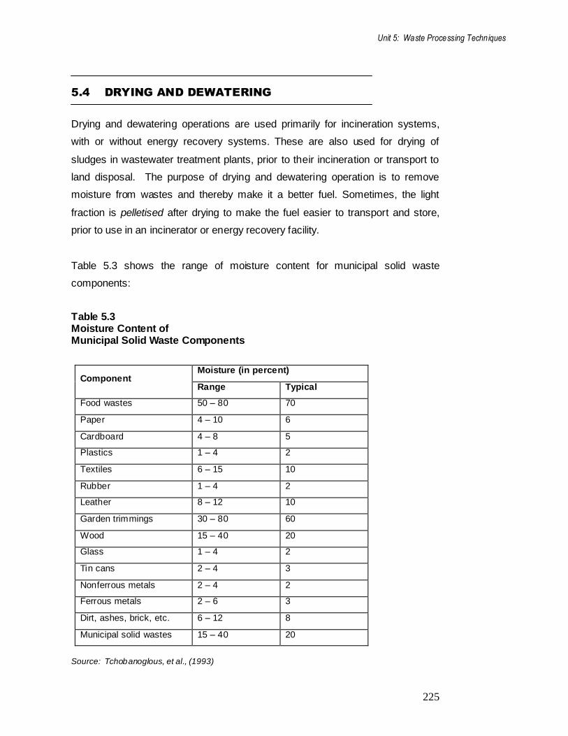
Table 5.3 shows the range of moisture content for municipal solid waste
components:
Table 5.3 Moisture Content of Municipal Solid Waste Components
Component Moisture (in percent)
Range Typical
Food wastes 50 – 80 70
Paper 4 – 10 6
Cardboard 4 – 8 5
Plastics 1 – 4 2
Textiles 6 – 15 10
Rubber 1 – 4 2
Leather 8 – 12 10
Garden trimmings 30 – 80 60
Wood 15 – 40 20
Glass 1 – 4 2
Tin cans 2 – 4 3
Nonferrous metals 2 – 4 2
Ferrous metals 2 – 6 3
Dirt, ashes, brick, etc. 6 – 12 8
Municipal solid wastes 15 – 40 20
Source: Tchobanoglous, et al., (1993)
226
5.4.1 Drying
The following three methods are used to apply the heat required for drying the
wastes:
(i) Convection drying: In this method, hot air is in direct contact with the wet
solid waste stream.
(ii) Conduction drying: In this method, the wet solid waste stream is in
contact with a heated surface.
(iii) Radiation drying: In this method, heat is transmitted directly to the wet
solid waste stream by radiation from the heated body.
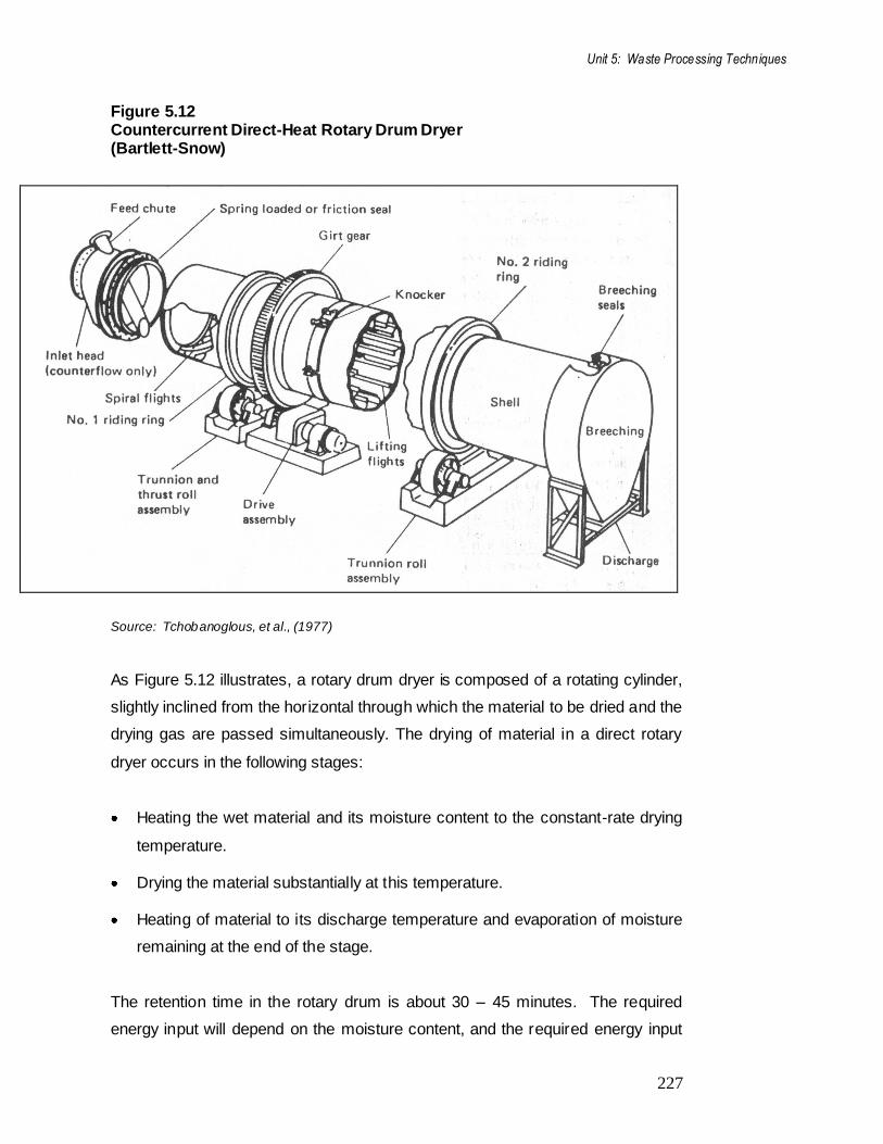
Of these three methods, convection drying is used most commonly. Figure 5.12
illustrates a rotary drum dryer used in the cement industry:
Unit 5: Waste Processing Techniques
227
Figure 5.12 Countercurrent Direct-Heat Rotary Drum Dryer (Bartlett-Snow)
Source: Tchobanoglous, et al., (1977)
As Figure 5.12 illustrates, a rotary drum dryer is composed of a rotating cylinder,
slightly inclined from the horizontal through which the material to be dried and the
drying gas are passed simultaneously. The drying of material in a direct rotary
dryer occurs in the following stages:
Heating the wet material and its moisture content to the constant-rate drying
temperature.
Drying the material substantially at this temperature.
Heating of material to its discharge temperature and evaporation of moisture
remaining at the end of the stage.
The retention time in the rotary drum is about 30 – 45 minutes. The required
energy input will depend on the moisture content, and the required energy input
228
can be estimated by using a value of about 715 KJ/kg (or 1850 Btu/1b) of water
evaporated. Some of the factors, we need to consider in the selection of a drying
equipment that include the following:
Properties of material to be dried.
Drying characteristics of the materials, including moisture content, maximum
material temperature and anticipated drying time.
Specification of final product, including moisture content.
Nature of operation, whether continuous or intermittent.
Operational characteristics, including energy requirements, maintenance
requirements, simplicity of operation, reliability, noise output and air and
water pollution control requirements.
Site considerations such as space and height access, noise and
environmental limitations.
5.4.2 Dewatering
Dewatering is more applicable to the problem of sludge disposal from wastewater
treatment of plants, but may also be applicable in some cases to
municipal/industrial waste problems. When drying beds, lagoons or spreading on
land are not feasible, other mechanical means of dewatering are used. The
emphasis in the dewatering operation is often on reducing the liquid volume.
Once dewatered, the sludge can be mixed with other solid waste, and the
resulting mixture can be:
incinerated to reduce volume;
used for the production of recoverable by-products;
used for production of compost;
buried in a landfill.
Unit 5: Waste Processing Techniques
229
Centrifugation and filtration are the two common methods for the dewatering of
sludge. Sludges with solid content of a few percent can be thickened to about 10
– 15% in centrifugation and about 20 – 30% in pressure filtration or vacuum
filtration.
LEARNING ACTIVITY 5.3
List the methods of drying. Note: a) Write your answer in the space given below. b) Check your answer with the one given at this end of this Unit.
230
SUMMARY
In this Unit, we discussed various processing techniques that are used in SWM
system to improve the efficiency of operation, recovery of resources, i.e., usable
materials, and recovery of conversion product and energy. We began our
discussion with the importance of processing techniques and the nature of
equipment involved for the purpose. Subsequently, we discussed mechanical
volume and size reduction techniques and touched upon chemical volume
reduction. We also explained some component separation techniques (air
separation, magnetic separation, screening, etc.). We closed the Unit with a
discussion on drying and dewatering, i.e., the processing techniques used for
removing varying amounts of moisture present in solid wastes.
SUGGESTED READINGS
Areivala, S.J. 1971. Solid Wastes Disposal in India, Central/Public Health
Engineering Institute. Nagpur.
Environmental Management in Developing Countries, 1995, Waste Management
Vol II, Institute for Scientific Co-operation, Tubingen.
Flintoff, R 1984. Management of Solid Wastes in Developing countries, WHO
Regional Publications, South east Asia Series 1
Arne Vesilind, William Worrel and Reinhart Debra, 2002. Solid waste
Engineering, Thomson Brooks/Cole, Singapore.
Ramachandra T.V. and Saira Varghese K. 2004. Environmentally sound options
for e-wastes management, ENVIS Journal of Human Settlements (ISSN 0971-
9091), March 2004.
Ramachandra T.V. and Saira Varghese K. 2003. Exploring possibilities of
achieving sustainability in solid waste management, Indian Jl Environmental
Health, 45 (4):255-264.

Unit 5: Waste Processing Techniques
231
Tchobaanoglous, G., Theisen, H., and Samuel A Vigil, 1993. Integrated Solid
Waste Management, McGraw-Hill, Inc., New Delhi.
UNEP. 1996. International Source Book on Environmentally Sound Technologies
for municipal Solid Waste Management (6), IETC, Osaka/Shiga.
US Environmental Protection Agency. 1989. Decision-Maker's Guide to Solid
Waste Management, Vol 1, Washington.
US Environmental Protection Agency.1995. Decision-Maker's Guide to Solid
Waste Management, Vol II, Washington.
http://ces.iisc.ernet.in/energy/SWMTR/TR85.html
Central Public Health and Environmental Engineering Organisation (CPHEEO)
and Ministry of Urban Development, Government of India, New Delhi (2000)
Manual on Municipal Solid Waste Management
REFERENCES
Phelps, H.O., Heinke. G. W., Jonker, J.F., Ouano, E.A.R. and Vandecasteele,
C.1995. Management of Solid Wastes, UNESCO, Paris.
Tchobanoglous, G., Theisen, H. and Eliassan, R..1977. Solid Wastes-
Engineering Principles and Management Issues, McGraw-Hill Book Company,
New York.
Tchobaanoglous, G., Theisen, H., and Samuel A Vigil, 1993. Integrated Solid
Waste Management, McGraw-Hill, Inc., New Delhi.

232
Lecture 5
Model Answers to Learning Activities
LEARNING ACTIVITY 5.1
Compaction of wastes is the method in which waste is densified so as to reduce
its volume. This is done to improve the efficiency of collection and disposal of
wastes. Compaction is done to increase the useful life of landfills and to reduce
the quantity of material handled at the disposal site. It also brings down the cost
involved in waste management.
Size reduction refers to the conversion of solid wastes into smaller portions. This
helps to obtain the final product in reasonably uniform and considerably reduced
size in comparison to the original form. It is important in the recovery of materials
for reuse and for conversion to energy. In order to make a better fuel for
incineration waste energy recovery facilities, size reduction is practised. It is also
used prior to moisture reduction, drying and dewatering.
LEARNING ACTIVITY 5.2
1 tonne = 1000 kg
The weight fraction of the glass in the feed is given by the equation:
Wf =
Weight of sample
Weight of material fed to the screen
=
100 1000 0.08 kg
100 1000 kg
= 0.08
Weight fraction of glass in screen underflow is given by:
Wu =
Weight of sample in underflow
Total weight of material in underflow

Unit 5: Waste Processing Techniques
233
=
7.2 1000 kg
10 1000
= 0.72
Recovery efficiency is given by the equation:
Recovery (%) =
Uwu
Fwu
=
10 1000 0.72 100100 1000 0.08
= 90%
Effectiveness is given by the equation:
Effectiveness = recovery rejection
= U Wu 1 - U(1 - Wu)
F W f F (1- Wf)
=
10 1000 0.72
100 1000 0.08 1
10 1000 1 0.72
100 1000 1 0.08
= 0.87
LEARNING ACTIVITY 5.3
The heat required for drying can be applied by the following methods:
(i) Convection drying in which hot air is in direct contact with the wet solid
waste stream.
(ii) Conduction drying in which wet solid waste stream is in contact with a
heated surface.
(iii) Radiation drying in which heat is transmitted directly to the wet solid
waste stream by radiation from the heated body.


![30801367 Upsr Writing Techniques and Model Answers[1]](https://static.fdocuments.in/doc/165x107/577d2bdf1a28ab4e1eab57f4/30801367-upsr-writing-techniques-and-model-answers1.jpg)


![Division R – SERVICES, N.E.C. · (1) Services providing skills and techniques related to waste disposal [“Waste disposal business”]. (2) Services providing skills and techniques](https://static.fdocuments.in/doc/165x107/5f53b874b97fba67775ee123/division-r-a-services-nec-1-services-providing-skills-and-techniques-related.jpg)


