Unit 5 mm9400 ver1.1(2014)
32
Newton’s Laws of Motion 5 - 1 Statics & Dynamics (MM9400) Version 1.1 Objectives: At the end of this unit, students should be able to: Understand the effect of forces on the motion of bodies State Newton's three laws of motion. Know the conditions under which each of the laws applies. Apply the equation "F = ma" to problems involving linear motion. Determine the displacement, time taken, velocity and acceleration for: (a) a body, e.g. car, moving with uniform acceleration or retardation (b) two bodies in motion and connected by an inextensible cable; (c) motion of a mass or connected masses on inclined planes. Sir Isaac Newton (1642 – 1727) Isaac Newton, English mathematician and physicist, was one of the inventors of the branch of mathematics called calculus. He solved the mysteries of light and optics, formulated the three laws of motion and derived from them the law of universal gravitation. Some quotations by Newton: “If I have ever made any valuable discoveries, it has been owing more to patient attention, than any other talent.” “I was like a boy playing on the sea- shore, and diverting myself now and then finding a smoother pebble or a prettier shell than ordinary, whilst the great ocean of truth lay all undiscovered before me” “It is the weight, not numbers of experiments that is to be regarded.” 5. NEWTON'S LAWS OF MOTION
-
Upload
allengineering -
Category
Engineering
-
view
74 -
download
0
Transcript of Unit 5 mm9400 ver1.1(2014)

Newton’s Laws of Motion 5 - 1
Statics & Dynamics (MM9400) Version 1.1
Objectives: At the end of this unit, students should be able to: Understand the effect of forces on the motion of bodies
State Newton's three laws of motion.
Know the conditions under which each of the laws applies.
Apply the equation "F = ma" to problems involving linear motion.
Determine the displacement, time taken, velocity and acceleration for:
(a) a body, e.g. car, moving with uniform acceleration or retardation (b) two bodies in motion and connected by an inextensible cable;
(c) motion of a mass or connected masses on inclined planes.
Sir Isaac Newton (1642 – 1727)
Isaac Newton, English mathematician and physicist, was one of the inventors of the branch of mathematics called calculus. He solved the mysteries of light and optics, formulated the three laws of motion and derived from them the law of universal gravitation.
Some quotations by Newton:
“If I have ever made any valuable discoveries, it has been owing more to patient attention, than any other talent.”
“I was like a boy playing on the sea-shore, and diverting myself now and then finding a smoother pebble or a prettier shell than ordinary, whilst the great ocean of truth lay all undiscovered before me”
“It is the weight, not numbers of experiments that is to be regarded.”
5. NEWTON'S LAWS OF MOTION

5 - 2 Newton’s Laws of Motion
Version 1.1 Statics & Dynamics (MM9400)
5.1 Introduction In this chapter, we begin to deal with that branch of Mechanics called Dynamics. Dynamics is the study of forces which produce a change in motion (acceleration or deceleration) of the body. This unit looks at the dynamics of linear motion. (The dynamics of bodies in circular motion will be dealt with in the unit on 'Torque & Moment of Inertia' in Mechanics II.) The relationship between force, mass and acceleration is summarised by Isaac Newton in his three laws of motion. 5.2 Newton's First Law of Motion This law states if the resultant external force is zero, then the body will either remain at rest or continue to move with constant speed in a straight line. To illustrate this law, consider the examples of a diver and a parachutist. Under the pull of gravity, the diver experiences a non-zero resultant force equal to her weight; this causes a downward acceleration of 9.81 m/s2 (see Fig 5.1). When the parachutist jumps off the aircraft, his initial vertical speed is zero. However, his weight pulling vertically downwards causes him to accelerate downward. As the parachute opens up, he will experience a sudden retardation as there is an upward force due to air resistance. This upward force will eventually be equal to the weight; the parachutist would then be in a state of vertical equilibrium (resultant force = 0) and will drift down with a constant speed (refer to Fig 5.2).
Fig. 5.1 Fig. 5.2
mg
Acceleration 9.81 m/s2
diver
Upward force F
mg
parachutist
Newton’s Laws of Motion 5 - 3
Statics & Dynamics (MM9400) Version 1.1
Fig. 5.3
m
V0 V1
F F m
t
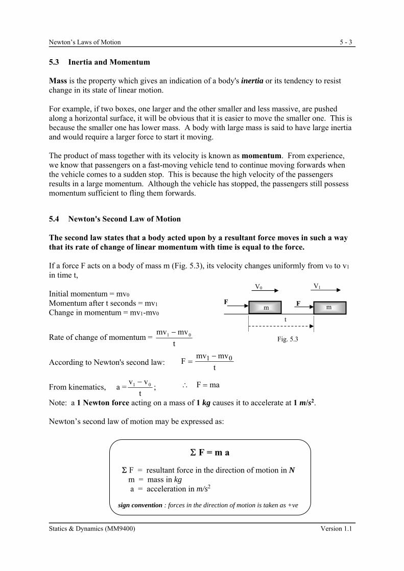
5.3 Inertia and Momentum Mass is the property which gives an indication of a body's inertia or its tendency to resist change in its state of linear motion. For example, if two boxes, one larger and the other smaller and less massive, are pushed along a horizontal surface, it will be obvious that it is easier to move the smaller one. This is because the smaller one has lower mass. A body with large mass is said to have large inertia and would require a larger force to start it moving. The product of mass together with its velocity is known as momentum. From experience, we know that passengers on a fast-moving vehicle tend to continue moving forwards when the vehicle comes to a sudden stop. This is because the high velocity of the passengers results in a large momentum. Although the vehicle has stopped, the passengers still possess momentum sufficient to fling them forwards.
5.4 Newton's Second Law of Motion The second law states that a body acted upon by a resultant force moves in such a way that its rate of change of linear momentum with time is equal to the force. If a force F acts on a body of mass m (Fig. 5.3), its velocity changes uniformly from v0 to v1 in time t, Initial momentum = mv0
Momentum after t seconds = mv1
Change in momentum = mv1-mv0
Rate of change of momentum = t
mvmv 01
According to Newton's second law:
From kinematics, a =t
vv 01 ;
Note: a 1 Newton force acting on a mass of 1 kg causes it to accelerate at 1 m/s2. Newton’s second law of motion may be expressed as:
t
mvmvF 01
maF
F = m a
F = resultant force in the direction of motion in N m = mass in kg a = acceleration in m/s2 sign convention : forces in the direction of motion is taken as +ve

5 - 4 Newton’s Laws of Motion
Version 1.1 Statics & Dynamics (MM9400)
5.5 Newton's Third Law of Motion This law states that to every action there is an equal and opposite reaction. If body A exerts a force (action) on body B (see Fig. 5.4), then body B exerts a force (reaction) of equal magnitude but in the opposite direction on body A. For example, when a block with mass m rests on a horizontal table, the mass exerts a downward force on the table equal to its weight 'mg'. According to Newton's third law, the table exerts a normal reaction vertically upwards on the block equal to 'mg' in magnitude. Example 5.1
A mass of 5 kg is dragged across a rough horizontal surface by a horizontal force of 20 N. If the frictional resistance to motion is equal to 5 N, what acceleration is produced? Resultant force Fx = ( ) N m = 5 kg Applying Newton's 2nd law of motion " F = ma " Example 5.2
What is the constant force required to give a mass of 10 kg initially at rest to a velocity of 30 m/s in 10 s? i) To find the acceleration a,
Using v1 = v0 + at ii) Applying Newton's law " Fx = ma " Resultant force Fx =
20 N 5 kg
a m/s2
5 N
A
B
A
Rn ( reaction )
mg ( action )
Fig. 5.4
m=10 kg
V0=0 V1=30 m/s
a m/s2
t = 0 s t =10 s
F m=10 kg
F

Newton’s Laws of Motion 5 - 5
Statics & Dynamics (MM9400) Version 1.1
Example 5.3
A bullet of mass 0.3 kg is fired into a fixed block of wood with velocity 300 m/s. If it is brought to rest in 0.1 s, find the resistance exerted by the wood assuming it to be uniform. Example 5.4 A body lying on a smooth horizontal surface is subjected to the action of three horizontal forces whose magnitudes and directions are as shown below. If the mass of the body is 10 kg, find its acceleration on the horizontal plane.
4 N 5 N
3 N
300
Plan View
t = 0 s t = 0.1 s
wood wood bullet
v = 300 m/s

5 - 6 Newton’s Laws of Motion
Version 1.1 Statics & Dynamics (MM9400)
Example 5.5 A lift with its load has a total mass of 2 tonnes (2000 kg). It is supported by a steel cable. Find the tension in the cable when the lift: a) is at rest, b) moves upwards with steady speed 1 m/s, c) moves downwards with steady speed 1 m/s, d) accelerates upwards with uniform acceleration 1 m/s2, e) accelerates downwards with uniform acceleration 1 m/s2.
MOTOR
LIFT CAR

Newton’s Laws of Motion 5 - 7
Statics & Dynamics (MM9400) Version 1.1
5.6 Tractive Effort & Tractive Resistance Tractive Effort `FTE' is the driving force exerted by the engine of a moving vehicle. Tractive Resistance `FTR' is the sum of all the resistance to motion due to drag and wind forces etc.
When travelling on the road, an incline or slope of 1 in 50 means that for every 50 m along the inclined surface(Fig. 5.6), there is an increase in vertical height or altitude of 1 m, i.e. sine of angle of inclination is given by sin = 1/50 Example 5.6
Determine the tractive effort needed to accelerate a car at 0.1 m/s2 down an incline of 1 in 100. The car has a mass of 1.5 tonne and the resistance to motion is 200 N.
Fig. 5.5 Tractive Effort and Resistance
FTR FTE
a m/s2
lorry
a m/s2
FTE FTR
Locomotive and train
1 100
θ
Fig. 5.6
1 50
θ
a
5 - 8 Newton’s Laws of Motion
Version 1.1 Statics & Dynamics (MM9400)
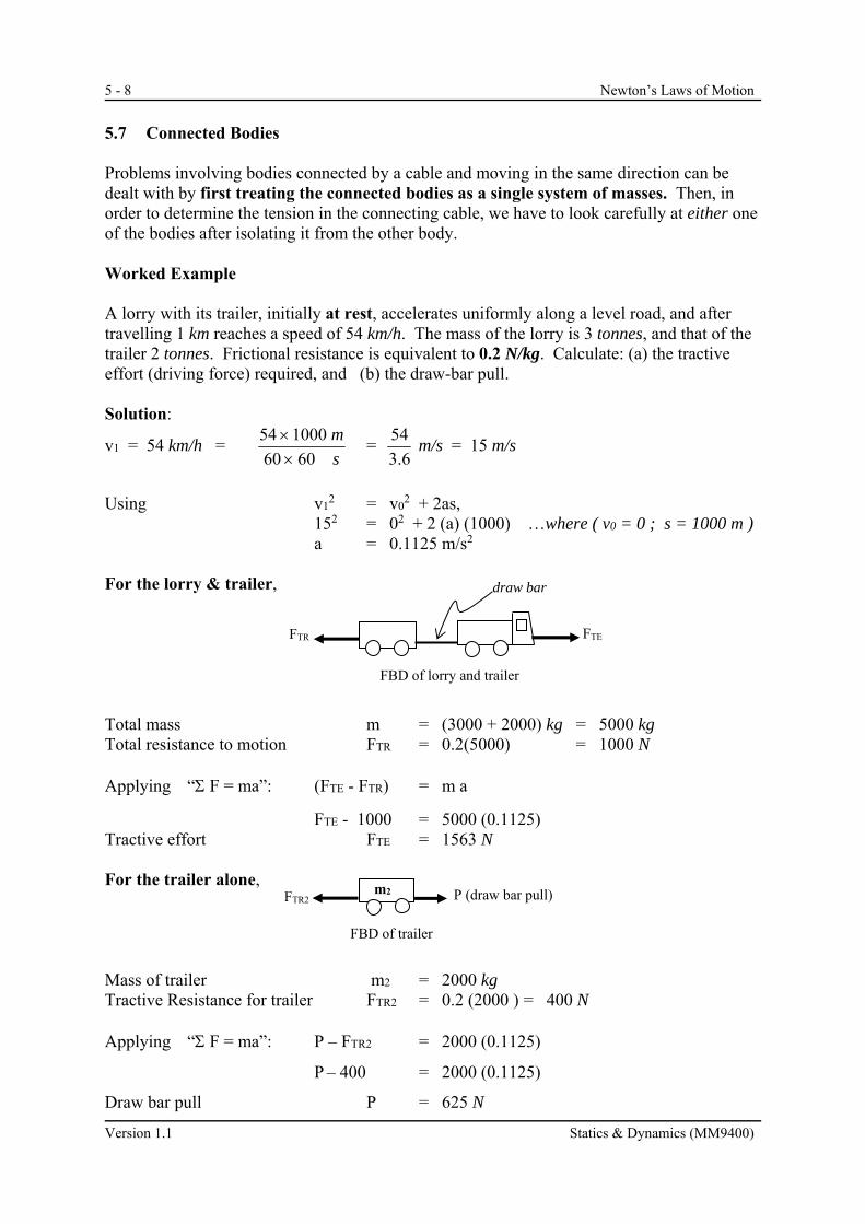
5.7 Connected Bodies Problems involving bodies connected by a cable and moving in the same direction can be dealt with by first treating the connected bodies as a single system of masses. Then, in order to determine the tension in the connecting cable, we have to look carefully at either one of the bodies after isolating it from the other body. Worked Example A lorry with its trailer, initially at rest, accelerates uniformly along a level road, and after travelling 1 km reaches a speed of 54 km/h. The mass of the lorry is 3 tonnes, and that of the trailer 2 tonnes. Frictional resistance is equivalent to 0.2 N/kg. Calculate: (a) the tractive effort (driving force) required, and (b) the draw-bar pull. Solution:
v1 = 54 km/h = s
m
6060
100054
= 6.3
54 m/s = 15 m/s
Using v1
2 = v02 + 2as,
152 = 02 + 2 (a) (1000) …where ( v0 = 0 ; s = 1000 m ) a = 0.1125 m/s2 For the lorry & trailer, Total mass m = (3000 + 2000) kg = 5000 kg Total resistance to motion FTR = 0.2(5000) = 1000 N Applying “ F = ma”: (FTE - FTR) = m a
FTE - 1000 = 5000 (0.1125) Tractive effort FTE = 1563 N For the trailer alone, Mass of trailer m2 = 2000 kg Tractive Resistance for trailer FTR2 = 0.2 (2000 ) = 400 N Applying “ F = ma”: P – FTR2 = 2000 (0.1125)
P – 400 = 2000 (0.1125)
Draw bar pull P = 625 N
m2 P (draw bar pull) FTR2
FBD of trailer
FTR FTE
FBD of lorry and trailer
draw bar

Newton’s Laws of Motion 5 - 9
Statics & Dynamics (MM9400) Version 1.1
Note: For a system of connected objects moving in different directions, a free-body diagram
is drawn for each object and "F = ma” is applied to each body separately. Both equations are then solved simultaneously for the acceleration and forces.
Example 5.7
A light non-extensible string is placed over a smooth pulley. To the ends of the string are attached masses of 2 kg and 1 kg and both parts of the string are vertical. If the masses are released from rest, determine:
(a) acceleration of the system (b) tension in the string (c) reaction at the axle of the pulley at A
2 kg
1 kg
Smooth pulley A
a
a
rotation
string string
α
2 kg
1 kg
A

5 - 10 Newton’s Laws of Motion
Version 1.1 Statics & Dynamics (MM9400)
Example 5.8
Two masses of 10 kg and 20 kg lie on smooth surfaces inclined at 60o and 30o to the horizontal respectively and are connected by a light non-extensible string that passes over a smooth pulley at the top of the planes. Determine: (a) tension in the string (b) acceleration of the system
600 300
smooth pulley
20 kg
10 kg
10 kg
600
20 kg
300

Newton’s Laws of Motion 5 - 11
Statics & Dynamics (MM9400) Version 1.1
TUTORIAL Multiple-Choice Items (Questions 5.1 to 5.9) 5.1 Which of the following units can be used to measure force?
a) kg b) m/s c) m/s2 d) kN
5.2 The force causing a body to accelerate has magnitude equal to the rate of change with
time of
a) velocity b) displacement c) momentum d) speed
5.3 Which pair of quantities are both vectors?
a) force and speed b) mass and acceleration c) velocity and weight d) momentum and speed
5.4 A concrete block has mass 30 kg. Its weight, in kN is
a) 0.294 b) 3.06 c) 30 d) 294
5.5 A 5 kg block, at rest on a smooth horizontal surface, is acted on by a resultant force of
2.5 N parallel to the surface. The acceleration of the block is a) 0.5 m/s2. b) 2.0 m/s2. c) 12.5 m/s2. d) 20.0 m/s2.
5 - 12 Newton’s Laws of Motion
Version 1.1 Statics & Dynamics (MM9400)
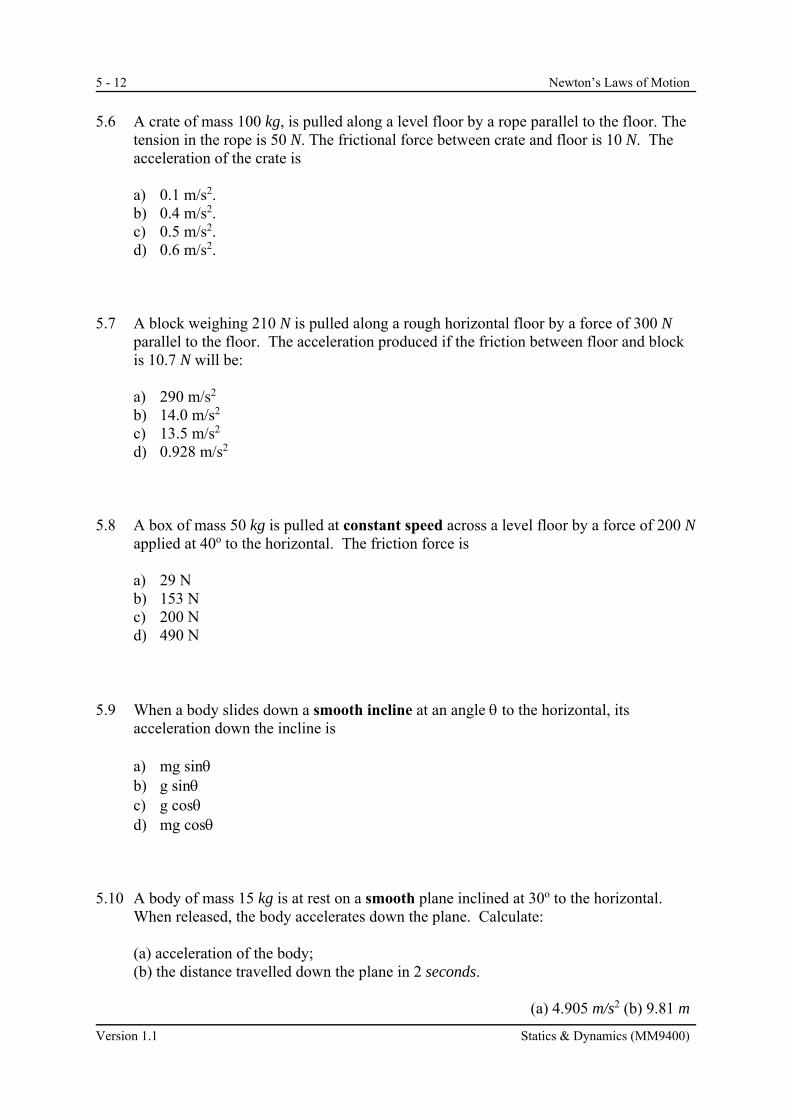
5.6 A crate of mass 100 kg, is pulled along a level floor by a rope parallel to the floor. The
tension in the rope is 50 N. The frictional force between crate and floor is 10 N. The acceleration of the crate is
a) 0.1 m/s2. b) 0.4 m/s2. c) 0.5 m/s2. d) 0.6 m/s2.
5.7 A block weighing 210 N is pulled along a rough horizontal floor by a force of 300 N
parallel to the floor. The acceleration produced if the friction between floor and block is 10.7 N will be:
a) 290 m/s2 b) 14.0 m/s2 c) 13.5 m/s2 d) 0.928 m/s2
5.8 A box of mass 50 kg is pulled at constant speed across a level floor by a force of 200 N
applied at 40o to the horizontal. The friction force is
a) 29 N b) 153 N c) 200 N d) 490 N
5.9 When a body slides down a smooth incline at an angle to the horizontal, its
acceleration down the incline is
a) mg sin b) g sin c) g cos d) mg cos
5.10 A body of mass 15 kg is at rest on a smooth plane inclined at 30o to the horizontal.
When released, the body accelerates down the plane. Calculate: (a) acceleration of the body; (b) the distance travelled down the plane in 2 seconds. (a) 4.905 m/s2 (b) 9.81 m

Newton’s Laws of Motion 5 - 13
Statics & Dynamics (MM9400) Version 1.1
5.11 A mass of 5 kg is accelerated from rest by a 50 N force acting up a rough plane inclined
at 40o to the horizontal. If the resistance against motion is 13.15 N, find: (a) the acceleration of the mass; (b) the time taken for the mass to reach a velocity of 1.5 m/s; (c) the distance moved up the slope before the mass reaches 1.5 m/s. (a) 1.064 m/s2, (b) 1.41 s, (c) 1.057 m 5.12 The 100 kg ball is held up by a cable as shown in Fig. Q5.12. Determine the tension in
the cable when the ball is: (a) stationary. (981 N) (b) released with an acceleration of 1.5 m/s2. (831 N)
100 kg
cable
Fig. Q5.12

5 - 14 Newton’s Laws of Motion
Version 1.1 Statics & Dynamics (MM9400)
5.13 A train increases its speed uniformly from 36 km/h to 72 km/h while travelling 1,600 m
up an incline of 1 in 120. The total mass of the train is 200 tonnes and the resistance to motion is 60 N/tonne. Calculate the tractive effort exerted by the locomotive.
( 47.1 kN ) 5.14 A motor car of mass 1.5 tonne is travelling at 50 km/h. The total resistance to motion
of the car is 350 N. (i) Determine the tractive effort required to accelerate the car to 80 km/h over a
distance of 270 m. (1186 N)
(ii) If a braking force of 600 N is applied when the car attains a speed of 80 km/h, determine the retardation of the car. (- 0.633 m/s2)
Newton’s Laws of Motion 5 - 15
Statics & Dynamics (MM9400) Version 1.1
5.15 (a) A vehicle of mass 1.5 tonne moving on a level road exerts a tractive effort of 1.8 kN.
The tractive resistance is 0.1 N/kg. Determine: (i) the acceleration of the vehicle. (1.1 m/s2) (ii) the time taken to reach a velocity of 50 km/h starting from rest. (12.63 s) (b) The vehicle reaches an upward slope of 10° to the horizontal. Determine the tractive effort required to maintain a steady velocity of 50 km/h up the slope. (2705 N) (c) If the engine is suddenly switched off ( tractive effort = 0 ), determine the: (i) retardation of the car. (- 1.8 m/s2) (ii) time taken to come to rest. (7.7 s) Note: Assume that the tractive resistance remains the same as in part (a).

5 - 16 Newton’s Laws of Motion
Version 1.1 Statics & Dynamics (MM9400)
5.16 A lorry of mass 1000 kg pulls a trailer of mass 450 kg on level ground. Resistance to motion for either vehicle is 4 N per kg of mass. Find the tension in the tow-bar and the tractive force of the engine when they are
(a) moving at a steady speed; ( 1800 N, 5800 N ) (b) accelerating at 0.6 m/s2. ( 2070 N , 6670 N ) 5.17 A car of mass 800 kg is pulling a trailer of mass 300 kg up a slope of angle to the
horizontal where sin = 1 / 200. Resistance to motion ( apart from gravity ) is 1.5 N per kg of mass for each vehicle. Calculate the tractive effort of the car and the tension in the tow-bar when they are
(a) moving with constant speed; ( 1704 N, 464.7 N ) (b) accelerating at 0.2 m/s2. ( 1924 N , 524.7 N )
Newton’s Laws of Motion 5 - 17
Statics & Dynamics (MM9400) Version 1.1
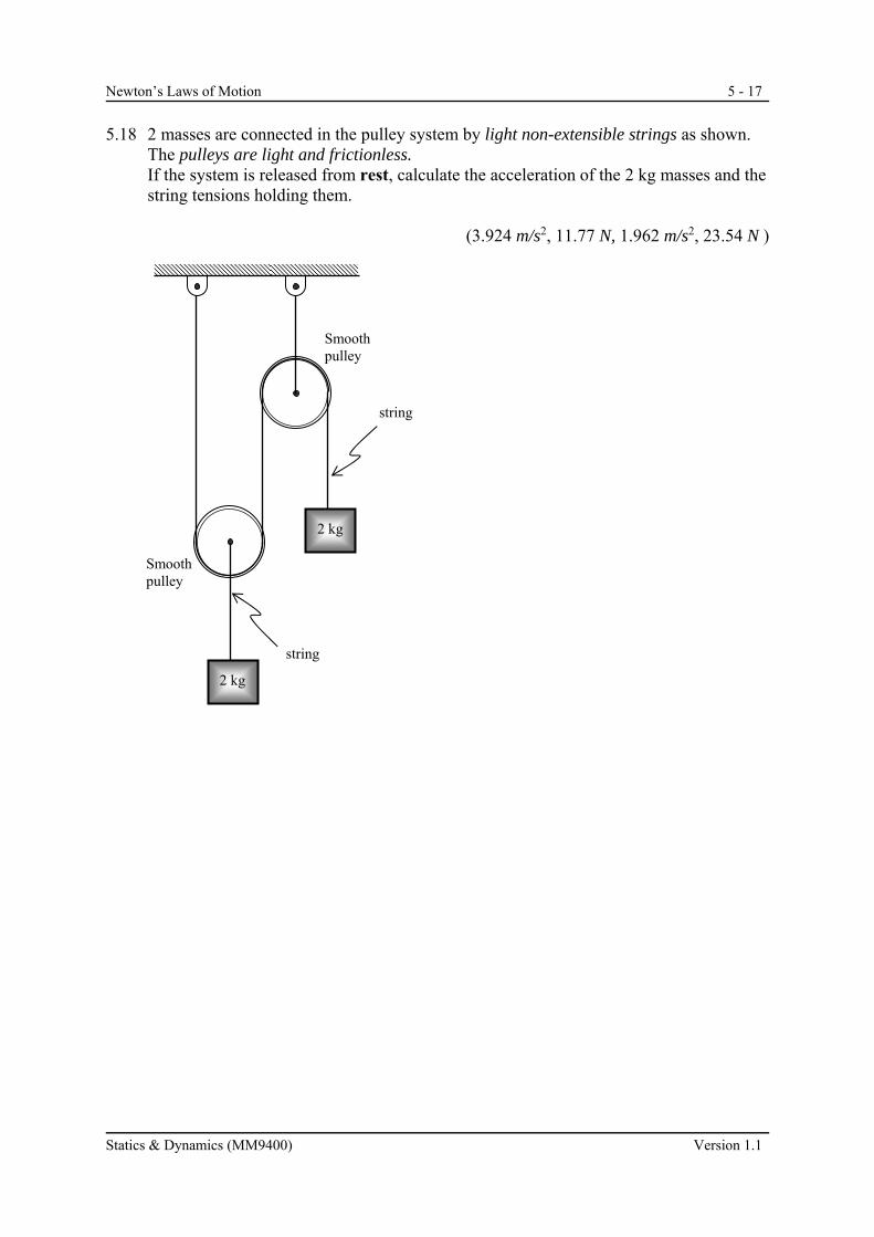
5.18 2 masses are connected in the pulley system by light non-extensible strings as shown.
The pulleys are light and frictionless. If the system is released from rest, calculate the acceleration of the 2 kg masses and the
string tensions holding them.
(3.924 m/s2, 11.77 N, 1.962 m/s2, 23.54 N )
Smooth pulley
Smooth pulley
2 kg
2 kg
string
string

5 - 18 Newton’s Laws of Motion
Version 1.1 Statics & Dynamics (MM9400)
5.19 Fig. Q5.19 shows two masses A and B of masses 0.75 kg and 0.5 kg respectively,
connected by a light inelastic string which passes over a frictionless pulley at C. The system is held at rest with A hanging freely while B is on a rough horizontal surface. The coefficient of kinetic friction between B and the surface is 0.4. Draw free body diagrams for A and B and determine:
(a) the acceleration of the system when the system is released; (4.32 m/s2) (b) the tension in the string. (4.12 N)
A
B 0.5 kg
0.75 kg
C
Fig. Q5.19

Newton’s Laws of Motion 5 - 19
Statics & Dynamics (MM9400) Version 1.1
5.20 Two masses, 30 kg and 20 kg, lie on surfaces inclined at 45o and 30o to the horizontal
respectively and are connected by a light non-extensible string which passes over a smooth pulley at the top of the planes (Fig. Q5.20). If the coefficient of kinetic friction between the masses and the surfaces is 0.1, determine:
a) acceleration of the system. (1.444 m/s2) b) tension in the string. (144.0 N ) Fig. Q5.20
450 300
smooth pulley
20 kg 30 kg
5 - 20 Newton’s Laws of Motion
Version 1.1 Statics & Dynamics (MM9400)
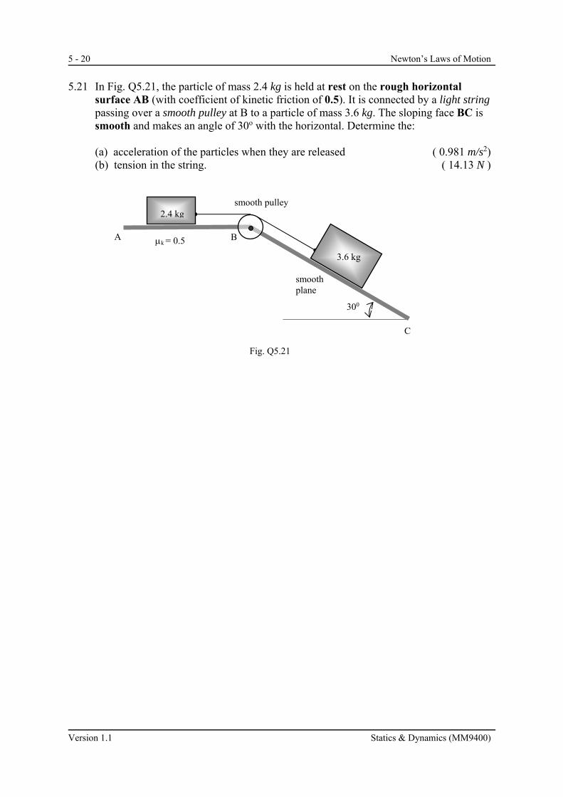
5.21 In Fig. Q5.21, the particle of mass 2.4 kg is held at rest on the rough horizontal
surface AB (with coefficient of kinetic friction of 0.5). It is connected by a light string passing over a smooth pulley at B to a particle of mass 3.6 kg. The sloping face BC is smooth and makes an angle of 30o with the horizontal. Determine the:
(a) acceleration of the particles when they are released ( 0.981 m/s2) (b) tension in the string. ( 14.13 N )
k = 0.5 A B
C
Fig. Q5.21
300
smooth pulley
3.6 kg
2.4 kg
smooth plane

Newton’s Laws of Motion 5 - 21
Statics & Dynamics (MM9400) Version 1.1
5.22 A smooth plane is inclined at 30o to the horizontal as shown in Fig. Q5.22. A mass of
9 kg placed on the plane is connected by a light non-extensible string via a smooth pulley at the top of the plane to a mass of 5 kg which hangs freely at a distance of H metres from the floor. The system is released from rest.
(a) Calculate the acceleration of the system. ( 0.35 m/s2) If the 5 kg mass reaches the floor after 2 seconds, determine: (b) the height, H; ( 0.7 m ) (c) the retardation of the 9 kg mass after this instant. ( 4.91 m/s2)
H
Fig. Q5.22
300
smooth pulley
9 kg
5 kg smooth plane

5 - 22 Newton’s Laws of Motion
Version 1.1 Statics & Dynamics (MM9400)
* 5.23 Elevators are merely lift cages for passengers moving up a lift shaft. They are pulled up
by a vertical steel cable which is wound onto a drum at the top of a building. A man weighing 50 kg rides in an elevator weighing 800 kg. The lift rises at 2 m/s, slowing down to a halt with uniform retardation over a distance of 4 m. (a) Calculate the retardation of the lift. (b) What is the tension of the steel rope pulling up the lift? (c) With the aid of a free-body diagram, calculate the normal reaction of the elevator
floor on the passenger.
(0.5 m/s2; 7914 N ; 465.5N )
Newton’s Laws of Motion 5 - 23
Statics & Dynamics (MM9400) Version 1.1
5.8 Torque
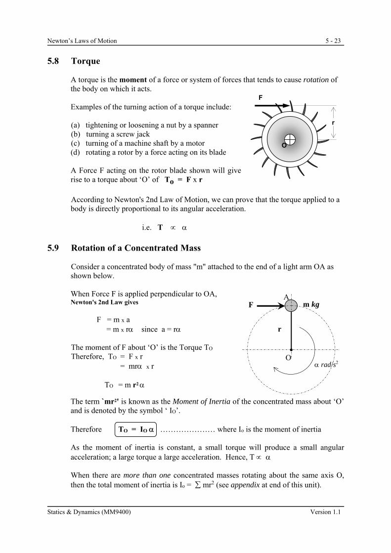
A torque is the moment of a force or system of forces that tends to cause rotation of the body on which it acts. Examples of the turning action of a torque include: (a) tightening or loosening a nut by a spanner (b) turning a screw jack (c) turning of a machine shaft by a motor (d) rotating a rotor by a force acting on its blade
A Force F acting on the rotor blade shown will give rise to a torque about ‘O’ of To = F x r
According to Newton's 2nd Law of Motion, we can prove that the torque applied to a body is directly proportional to its angular acceleration.
i.e. T 5.9 Rotation of a Concentrated Mass
Consider a concentrated body of mass "m" attached to the end of a light arm OA as shown below.
When Force F is applied perpendicular to OA, Newton's 2nd Law gives
F = m x a = m x r since a = r
The moment of F about ‘O’ is the Torque TO
Therefore, TO = F x r = mr x r TO = m r2
The term `mr2' is known as the Moment of Inertia of the concentrated mass about ‘O’ and is denoted by the symbol ‘ IO’. Therefore TO = IO ………………… where Io is the moment of inertia
As the moment of inertia is constant, a small torque will produce a small angular acceleration; a large torque a large acceleration. Hence, T
When there are more than one concentrated masses rotating about the same axis O,
then the total moment of inertia is Io = mr2 (see appendix at end of this unit).
O
F
r
F m kg
r
O rad/s2
A
5 - 24 Newton’s Laws of Motion
Version 1.1 Statics & Dynamics (MM9400)
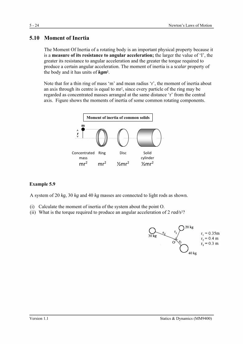
5.10 Moment of Inertia
The Moment Of Inertia of a rotating body is an important physical property because it is a measure of its resistance to angular acceleration; the larger the value of ‘I’, the greater its resistance to angular acceleration and the greater the torque required to produce a certain angular acceleration. The moment of inertia is a scalar property of the body and it has units of kgm2.
Note that for a thin ring of mass ‘m’ and mean radius ‘r’, the moment of inertia about an axis through its centre is equal to mr2, since every particle of the ring may be regarded as concentrated masses arranged at the same distance ‘r’ from the central axis. Figure shows the moments of inertia of some common rotating components.
Example 5.9 A system of 20 kg, 30 kg and 40 kg masses are connected to light rods as shown. (i) Calculate the moment of inertia of the system about the point O. (ii) What is the torque required to produce an angular acceleration of 2 rad/s2?
Concentrated mass
mr2
Disc
½mr2
Solidcylinder
½mr2
Ring
mr2
r
Moment of inertia of common solids
m

Newton’s Laws of Motion 5 - 25
Statics & Dynamics (MM9400) Version 1.1
5.11 Radius of Gyration
For objects that cannot be described as simple geometrical shapes, then we have to introduce the concept of radius of gyration. The moment of inertia depends on:
(i) the mass of the body (ii) the way the mass is distributed about the axis of rotation
Mathematically, we say: IO = m ko
2
where m = total mass of the body in kg. kO = the radius of gyration about ‘O’ in metres
The radius of gyration about ‘O’ is a mathematical measure of the way the mass of a given body is distributed or shaped about an axis passing through ‘O’. The radius of gyration has units of length (e.g. metres or millimetres).
Usually, the radii of gyration for bodies of various shapes are known and can be read directly from tables of engineering data.
5.12 Rotation of Shaft
A shaft carrying a flywheel has moment of inertia I about the axis of rotation. If the shaft is supported on bearings, friction in the bearings will give rise to a friction torque which resists rotation of the shaft. Assume that this friction torque, Tf , is constant. An applied torque, Ta , is required to produce angular acceleration, hence Applying T = I Ta - Tf = I
The friction torque is preceded by a negative sign to show that Tf opposes the direction of rotation.
A positive applied torque causes acceleration, while one that causes retardation will usually be negative, i.e. is applied in a direction which opposes the motion.
Figure a free body diagram of the rotating body.
O
R
W
Ta
Tf

5 - 26 Newton’s Laws of Motion
Version 1.1 Statics & Dynamics (MM9400)
Example 5.10 A uniform circular flywheel with moment of inertia of 0.5 kgm2 about its central axis is mounted on a shaft of negligible mass. If the friction torque at the bearings is 0.3 Nm, calculate the: (a) angular velocity reached after applying a torque of 1.5 Nm for 10 seconds to the shaft at
rest. (b) applied torque required to maintain rotation at the same angular velocity after the 10
seconds. (c) angular retardation if a 1 Nm braking torque is applied to the disc.

Newton’s Laws of Motion 5 - 27
Statics & Dynamics (MM9400) Version 1.1
5.13 Hoist Drum With Hanging Load If a load is hung from a circular drum as shown, it is possible to raise or lower the load by rotating the drum. In considering either the upward or downward motion of the load, two equations can be found: (i) The equation for the resultant force acting on the load,
F = ma (ii) The equation for the resultant torque acting about centre of the hoist drum,
T = I .
(iii) A third equation required is ‘a = r’ [a] Load being raised
Ta = Applied torque Tf = Friction torque F = Tension in rope F. r = Torque due to tension The two equations are:
F - mg = ma ……… for the Load
Ta – F.r - Tf = I ……….for the drum
[b] Load being lowered with braking torque
A negative torque Ta is applied by means of brakes to retard the load as it is being lowered.
F.r –Ta – Tf = I ……….for the drum mg – F = ma ……… for the Load
Note:
When a braking torque is applied, the load will retard and gradually come to rest, so is negative.
If no braking torque is applied (i.e. Ta = 0), the load is resisted only by bearing friction and is usually positive. This situation is to be avoided because of the danger of the weight falling at high speed.
m
r
Hoist drum
load
a
O
R
W
Ta
Tf
F
a
m
F
mg
O
R
W
Ta
Tf
F
a
m
F
mg

5 - 28 Newton’s Laws of Motion
Version 1.1 Statics & Dynamics (MM9400)
Example 5.11 A winch drum is used to raise a load of 100 kg with an acceleration of 1.2 m/s2 as shown in the figure below. The mass moment of inertia of the drum is 12 kg m2 and its diameter is 0.6 m. The friction couple at the drum bearings is 45 Nm.
(a) Draw free body diagrams for the load and the drum.
(b) Determine the: (i) tension in the cable (ii) angular acceleration of the drum.
(iii) torque that must be applied at the drum to accelerate the load. (iv) time taken for the load to reach a velocity of 4 m/s.
(v) applied torque required to maintain the load at this speed.
m
r
Winchdrum
load
a

Newton’s Laws of Motion 5 - 29
Statics & Dynamics (MM9400) Version 1.1
Example 5.12 A circular flywheel is mounted on a horizontal shaft of radius 25 mm as shown in the figure below. The shaft is supported on bearings. Around the shaft is wrapped a light cord from which is hung a 2 kg mass. When allowed to fall and rotate the flywheel, the mass falls vertically 1.5 m in 5 seconds from rest. The friction torque at the bearings is 0.3 Nm. (a) Sketch the Free Body Diagram of:
(i) the 2 kg mass (ii) the shaft.
(b) Determine the: (i) linear acceleration of the 2 kg mass. (ii) tension in the cord.
(iii) moment of inertia of the flywheel and shaft about the central axis.
(iv) radius of gyration of the flywheel about its central axis, given that the mass of the flywheel and shaft is 4.3 kg.
Shaft
2 kg mass
Flywheel
5 - 30 Newton’s Laws of Motion
Version 1.1 Statics & Dynamics (MM9400)
5.24 A flywheel has moment of inertia of 10 kgm2. Calculate the angular acceleration of
the wheel due to an applied torque of 8 Nm if the bearing friction is equivalent to a couple of 3 Nm.
(0.5 rad/s2)
5.26 A light shaft carries a steam-driven turbine rotor of mass 2 tonnes and a radius of
gyration of 600 mm. The rotor requires a uniform torque of 1.2 kNm to accelerate it from rest to 6,000 rev/min in 10 min. Find:
(a) the friction torque; (b) the time taken to come to rest when the steam is shut off.
(446 Nm; 16.9 min) 5.27 A flywheel of 35 kg mass has a radius of gyration of 150 mm. From a speed of 350
rpm, the flywheel is retarded by a braking torque which brings it to rest in 15 revs. Assuming the friction couple at the bearings to be 0.57 Nm, determine:
(a) the moment of inertia of the flywheel; (0.788 kgm2)
(b) its angular retardation; (-7.13 rad/s2) (c) the braking torque required. (5.04 Nm) 5.28 A hoist drum raises a cage of mass 600 kg through a height of 120 m. The drum has a
mass of 250 kg and an effective diameter of 1 m and a radius of gyration of 0.36 m. There is a frictional torque of 200 Nm at the drum bearings.
The cage initially has an acceleration of 1.5 m/s2 until a velocity of 9 m/s is reached, after which the velocity is constant until the cage nears the top, when the final retardation is 6 m/s2. Find the: (a) starting torque applied to the drum. (3690 Nm) (b) displacement of the cage during retardation. (6.75 m) (c) total time taken for the cage to reach to the top. (17.1 s) (d) applied torque required for the cage to be raised at a constant velocity of 9 m/s. (3143 Nm)
5.29 A mass of 18 kg attached to a cord, which is wrapped round the 50 mm diameter spindle of a flywheel, descends and thereby causes the flywheel to rotate. If the mass descends 1.8 m in 10 seconds and the friction torque is 0.35 Nm,
(a) find the moment of inertia of the flywheel. (b) if the flywheel weighs 981 N, what is its radius of gyration?
(2.81 kgm2, 0.168 m)

Newton’s Laws of Motion 5 - 31
Statics & Dynamics (MM9400) Version 1.1
5.30 A solid cylindrical winch drum is used to lower a 15 kg lift cage vertically. The
winch drum has a mass of 25 kg, radius of gyration 0.5 m and experiences a friction couple of 25 Nm. The cage was lowered under the action of a braking torque with an acceleration of 1 m/s2 until a velocity of 10 m/s is reached. After this, it moves with uniform velocity for 25 m. Another applied braking torque then retards the drum to rest uniformly. The cage descended a total distance of 150 m.
(a) Find the radius of the cylindrical winch drum. (0.707 m) (b) What is the braking torque required during acceleration? (59.59 Nm)
(c) Sketch the velocity vs time graph and find the deceleration. (0.67 m/s2) (d) What is the braking torque required during retardation? (92 Nm) 5.31 A winch drum is used to lower a 22 kg lift cage vertically as shown below. The winch
drum has a mass of 55 kg, an effective diameter of 0.6m and a radius of gyration of 0.45 m.The friction torque at the drum bearing is 25 Nm. The cage is lowered from 10 m/s to rest under the action of the braking torque through a distance of 50 m.
(a) Sketch the Free Body Diagrams of the cage and the winch drum (b) Determine the deceleration of the cage and tension in the cord. (a = -1 m/s2 , 237.82 N) (c) Find the braking torque required during deceleration. ( Tb = 83.47 Nm)
Winch Drum Cage Motion
Smooth pulley
Cable

5 - 32 Newton’s Laws of Motion
Version 1.1 Statics & Dynamics (MM9400)
APPENDIX
Rotation of a Distributed Mass
In general, a body is composed of many small particles of mass m1, m2, m3, .... etc.
The sum of these small masses ( m) gives the total mass of the body. If the body is rotated about ‘0’ with an angular acceleration rad/s2, a torque T0 has to be applied .
The resultant torque about the axis of rotation ‘O’ can be found by adding up all the individual torques needed to accelerate each particle making up the whole body. Consider a particle of mass mi in a body, at distance ri from an axis through O.
Let ai = linear acceleration of particle, = angular acceleration of body
Thus, force on particle Fi = mi a i (Newton's 2nd Law)
= m i ( r i ) (since a i = r i )
Moment of this force about 'O' Ti = (m i r i ) x r i
= (m i r i 2)
Adding up moments (or torque) on every particle
= ( m1r1 2 ) + ( m2r2
2 ) + ( m3r3 2 ) + ...
= ( mr2 ) (Since is a constant for all particles) Since the summation of moments about ‘O’ of all the particles = resultant torque T0 on the whole body, ( mr2) = T0 . For the distributed mass, the expression
(mr2 ) is constant and represents the moment of inertia about ‘O’. We observe again that To is directly proportional to . In general, the relation between resultant
torque and angular acceleration can be stated as “To = Io ”. In addition, we note
that for concentrated and distributed masses, the moment of inertia about ‘O’ is given be I0 = mr2.
Total mass = m