
Estimate of tsunami sourceusing optimized unit sources and ...
Unit Four
PLAN DEVELOPMENT, INFORMATION SOURCES, PLAN REVIEW, AND INSPECTIONS
Introduction
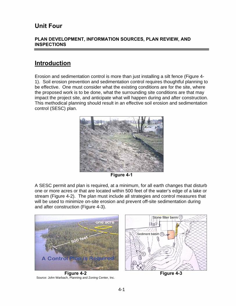
Erosion and sedimentation control is more than just installing a silt fence (Figure 4-1). Soil erosion prevention and sedimentation control requires thoughtful planning to be effective. One must consider what the existing conditions are for the site, where the proposed work is to be done, what the surrounding site conditions are that may impact the project site, and anticipate what will happen during and after construction. This methodical planning should result in an effective soil erosion and sedimentation control (SESC) plan.
Figure 4-1
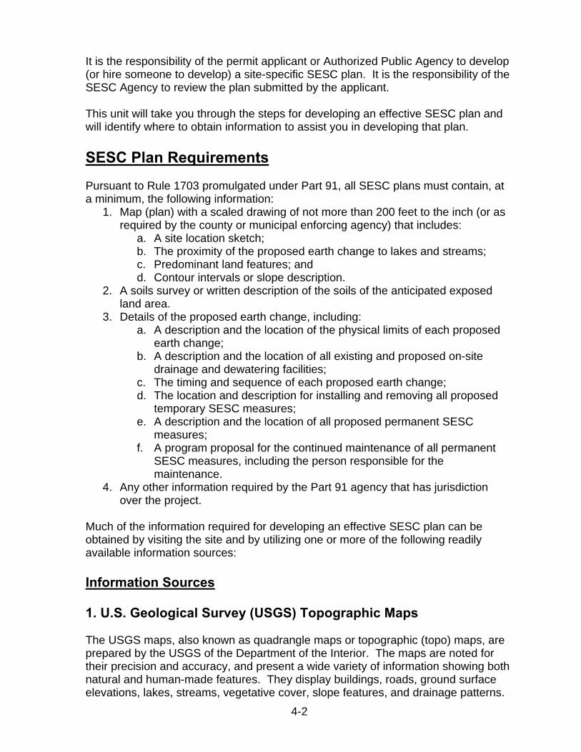
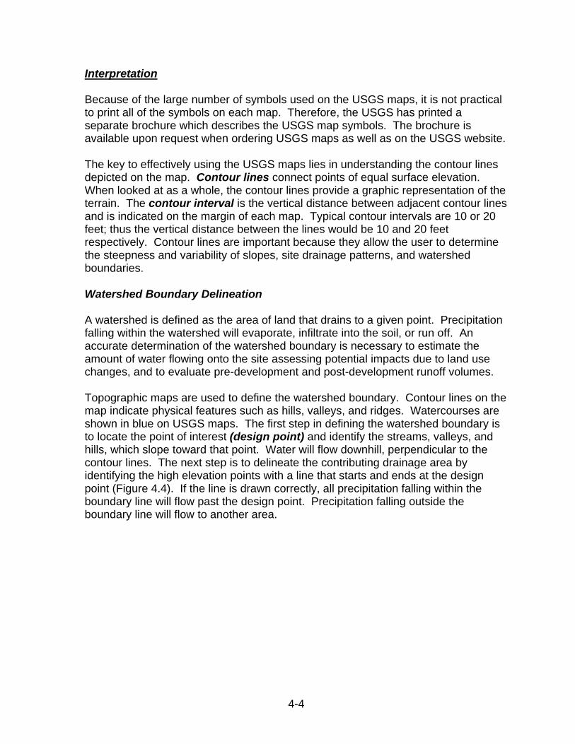
A SESC permit and plan is required, at a minimum, for all earth changes that disturb one or more acres or that are located within 500 feet of the water’s edge of a lake or stream (Figure 4-2). The plan must include all strategies and control measures that will be used to minimize on-site erosion and prevent off-site sedimentation during and after construction (Figure 4-3).
4-1
Figure 4-2 Source: John Warbach, Planning and Zoning Center, Inc.
Stone filter berm
Sediment basin
Figure 4-3
4-2
It is the responsibility of the permit applicant or Authorized Public Agency to develop (or hire someone to develop) a site-specific SESC plan. It is the responsibility of the SESC Agency to review the plan submitted by the applicant.
This unit will take you through the steps for developing an effective SESC plan and will identify where to obtain information to assist you in developing that plan.
SESC Plan Requirements Pursuant to Rule 1703 promulgated under Part 91, all SESC plans must contain, at a minimum, the following information:
1. Map (plan) with a scaled drawing of not more than 200 feet to the inch (or asrequired by the county or municipal enforcing agency) that includes:
a. A site location sketch;b. The proximity of the proposed earth change to lakes and streams;c. Predominant land features; andd. Contour intervals or slope description.
2. A soils survey or written description of the soils of the anticipated exposedland area.
3. Details of the proposed earth change, including:a. A description and the location of the physical limits of each proposed
earth change;b. A description and the location of all existing and proposed on-site
drainage and dewatering facilities;c. The timing and sequence of each proposed earth change;d. The location and description for installing and removing all proposed
temporary SESC measures;e. A description and the location of all proposed permanent SESC
measures;f. A program proposal for the continued maintenance of all permanent
SESC measures, including the person responsible for themaintenance.
4. Any other information required by the Part 91 agency that has jurisdictionover the project.
Much of the information required for developing an effective SESC plan can be obtained by visiting the site and by utilizing one or more of the following readily available information sources:
Information Sources
1. U.S. Geological Survey (USGS) Topographic Maps
The USGS maps, also known as quadrangle maps or topographic (topo) maps, are prepared by the USGS of the Department of the Interior. The maps are noted for their precision and accuracy, and present a wide variety of information showing both natural and human-made features. They display buildings, roads, ground surface elevations, lakes, streams, vegetative cover, slope features, and drainage patterns.

4-3
Availability The USGS maps for Michigan may be purchased from the Michigan United Conservation Clubs in Lansing, Michigan Department of Natural Resources (MDNR) at https://www.michigan.gov/som/0,4669,7-192-78943_78944---,00.html, USGS at http://www.usgs.gov/pubprod , and at some local retail stores. The USGS provides a list, by state, of all businesses that sell USGS maps on their website. These maps can also be accessed on the Internet at www.topozone.com .
USGS maps are available in many scales, such as: 1:250,000, 1:100,000, 1:62,500, 1:25,000, and 1:24,000. The scale represents a ratio of units on the map to units on the land surface. For example, a scale of 1:24,000 means that one inch on the map represents 24,000 inches (2,000 feet) along the land surface. Think of the ratio as a fraction: the smaller the second number or denominator (e.g., 24,000), the larger the fraction or scale of the map. Large scale maps (e.g. 1/24,000) show a smaller area and thus more detail than small scale maps (e.g. 1/250,000).
The 1:24,000 scale maps are available for all or most of Michigan and are the most detailed maps available from the USGS. One inch on the map equals 2000 feet. These maps are also referred to as 7.5 minute maps because they show an area that spans 7.5 minutes of latitude and 7.5 minutes of longitude. Because the lines that represent longitude are not parallel, the areas covered by the USGS maps are somewhat variable. In Michigan, the area covered by one 7.5 minute map ranges from 49.8 to 55.75 square miles; the average area is 53.3 square miles.
The 1:25,000 maps are very similar to the 1:24,000 scale maps but they are in metric units. On these maps one inch equals approximately 2,083 feet.
A useful conversion factor to remember when using ratio scales is that one-mile equals 63,360 inches. Using this conversation factor and the following calculations, a distance of 2.25 inches on a 1:24,000 scale map would equal 0.85 miles of land surface.
2.25 inches x 24,000 inches/inch = 54,000 inches 54,000 inches (of land surface) divided by 63,360 inches/mile = 0.85 miles
One word of caution, when using ratio scales, such as 1:24,000, or other types of proportional scales, such as fractional (1/24,000) or narrative (e.g., one inch equals one mile), the scales become meaningless if the maps are reduced or enlarged in size. In contrast, graphic map scales, such as bar scales that resemble a segment of a ruler, remain valid when the maps are enlarged or reduced in size.
4-4
Interpretation
Because of the large number of symbols used on the USGS maps, it is not practical to print all of the symbols on each map. Therefore, the USGS has printed a separate brochure which describes the USGS map symbols. The brochure is available upon request when ordering USGS maps as well as on the USGS website.
The key to effectively using the USGS maps lies in understanding the contour lines depicted on the map. Contour lines connect points of equal surface elevation. When looked at as a whole, the contour lines provide a graphic representation of the terrain. The contour interval is the vertical distance between adjacent contour lines and is indicated on the margin of each map. Typical contour intervals are 10 or 20 feet; thus the vertical distance between the lines would be 10 and 20 feet respectively. Contour lines are important because they allow the user to determine the steepness and variability of slopes, site drainage patterns, and watershed boundaries.
Watershed Boundary Delineation
A watershed is defined as the area of land that drains to a given point. Precipitation falling within the watershed will evaporate, infiltrate into the soil, or run off. An accurate determination of the watershed boundary is necessary to estimate the amount of water flowing onto the site assessing potential impacts due to land use changes, and to evaluate pre-development and post-development runoff volumes.
Topographic maps are used to define the watershed boundary. Contour lines on the map indicate physical features such as hills, valleys, and ridges. Watercourses are shown in blue on USGS maps. The first step in defining the watershed boundary is to locate the point of interest (design point) and identify the streams, valleys, and hills, which slope toward that point. Water will flow downhill, perpendicular to the contour lines. The next step is to delineate the contributing drainage area by identifying the high elevation points with a line that starts and ends at the design point (Figure 4.4). If the line is drawn correctly, all precipitation falling within the boundary line will flow past the design point. Precipitation falling outside the boundary line will flow to another area.
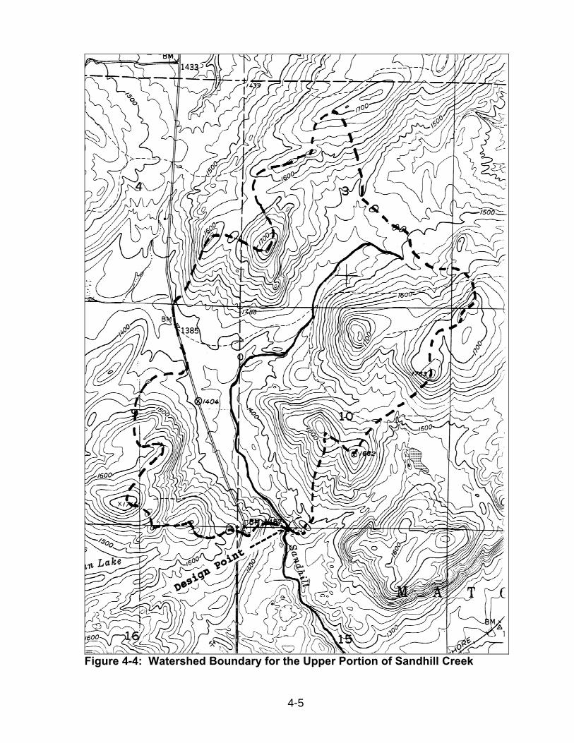
Figure 4-4: Watershed Boundary for the Upper Portion of Sandhill Creek
4-5
4-6
Limitations
• Check the date of map preparation, which is printed in the bottom right corner ofmost USGS maps. The date of preparation is important because the informationconcerning human-made features may be outdated in areas where considerabledevelopment has occurred. New roads or highways may modify the naturaldrainage patterns of an area and urban development may alter the flowcharacteristics of existing streams.
• The USGS topographic maps normally do not provide sufficient detail requiredfor developing soil erosion and sedimentation control plans for specific sites.These maps, however, may be the only information available for planning long,corridor-type projects such as pipelines.
• The USGS topographic 1:24,000 scale maps for Michigan have contour intervalsof 5 or 10 feet. Slopes significant enough to require soil erosion andsedimentation control measures may not always show up on a USGStopographic map; therefore, more detailed topographic surveys may be required.
2. Topographic Surveys
Topographic surveys provide very detailed information concerning the terrain of a specific area. These maps are generally prepared by a surveying or engineering firm. Aerial photographs or field surveys provide the basic data from which topographic maps are prepared. A topographic survey provides very detailed data about drainage patterns and slopes. Contour intervals on topographic surveys are generally 1-2 feet.
Availability
Unlike the USGS topographic maps that cover the entire state, topographic surveys are generally unavailable. Availability is limited to the sites for which the maps have been specifically prepared. In some instances, the following sources may have surveys available for adjacent areas:
• Local, state, and governmental agencies such as planning departments, roadcommissions, drain commissioners, and municipal engineering departments.For example, Oakland and Wayne counties have maps with 2-foot contoursavailable for their respective counties.
• Private utility companies.
• Professional land surveyors or aerial surveying firms.
Scales
Topographic surveys are prepared at a scale comparable to the final scale of site plan drawings. Typically, they are drawn at scales between 1-inch equals 20 feet (1:240) to 1-inch equals 200 feet (1:2400).
Limitations
• Availability is limited.
• Topographic surveys generally identify only on-site information.
• Aerial photographs from which topographic maps are drawn can only betaken at certain times of the year, when the trees are free of foliage and theland surface is not covered by snow.
Slope Profiles
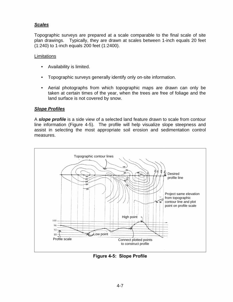
A slope profile is a side view of a selected land feature drawn to scale from contour line information (Figure 4-5). The profile will help visualize slope steepness and assist in selecting the most appropriate soil erosion and sedimentation control measures.
Topographic contour lines
Desired profile line
Project same elevation from topographic contour line and plot point on profile scale
High point
Low point Profile scale Connect plotted points
to construct profile
Figure 4-5: Slope Profile
4-7
Slope
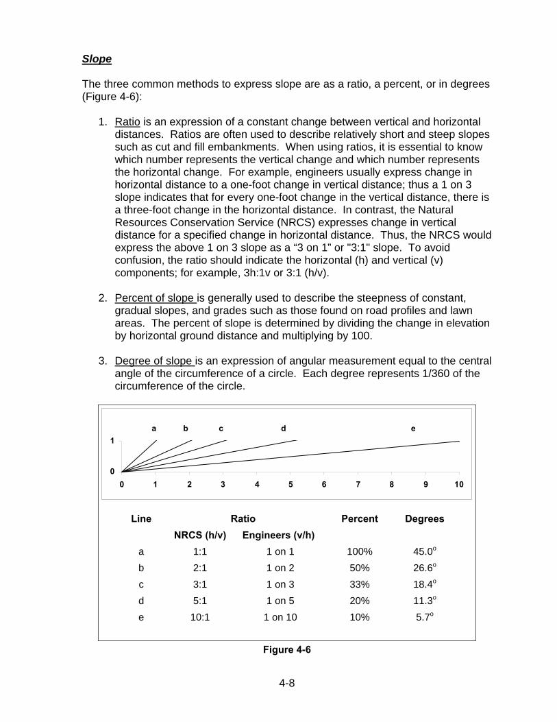
The three common methods to express slope are as a ratio, a percent, or in degrees (Figure 4-6):
1. Ratio is an expression of a constant change between vertical and horizontaldistances. Ratios are often used to describe relatively short and steep slopessuch as cut and fill embankments. When using ratios, it is essential to knowwhich number represents the vertical change and which number representsthe horizontal change. For example, engineers usually express change inhorizontal distance to a one-foot change in vertical distance; thus a 1 on 3slope indicates that for every one-foot change in the vertical distance, there isa three-foot change in the horizontal distance. In contrast, the NaturalResources Conservation Service (NRCS) expresses change in verticaldistance for a specified change in horizontal distance. Thus, the NRCS wouldexpress the above 1 on 3 slope as a “3 on 1” or "3:1" slope. To avoidconfusion, the ratio should indicate the horizontal (h) and vertical (v)components; for example, 3h:1v or 3:1 (h/v).
2. Percent of slope is generally used to describe the steepness of constant,gradual slopes, and grades such as those found on road profiles and lawnareas. The percent of slope is determined by dividing the change in elevationby horizontal ground distance and multiplying by 100.
3. Degree of slope is an expression of angular measurement equal to the centralangle of the circumference of a circle. Each degree represents 1/360 of thecircumference of the circle.
a b c d e
0
1
0 1 2 3 4 5 6 7 8 9 10
Line Ratio Percent Degrees NRCS (h/v) Engineers (v/h)
a 1:1 1 on 1 100% 45.0o
b 2:1 1 on 2 50% 26.6o
c 3:1 1 on 3 33% 18.4o
d 5:1 1 on 5 20% 11.3o
e 10:1 1 on 10 10% 5.7o
Figure 4-6
4-8
3. County Soil Surveys
Application to Soil Erosion and Sedimentation Control Planning
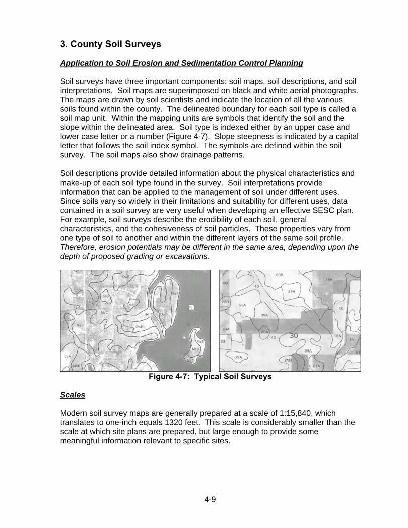
Soil surveys have three important components: soil maps, soil descriptions, and soil interpretations. Soil maps are superimposed on black and white aerial photographs. The maps are drawn by soil scientists and indicate the location of all the various soils found within the county. The delineated boundary for each soil type is called a soil map unit. Within the mapping units are symbols that identify the soil and the slope within the delineated area. Soil type is indexed either by an upper case and lower case letter or a number (Figure 4-7). Slope steepness is indicated by a capital letter that follows the soil index symbol. The symbols are defined within the soil survey. The soil maps also show drainage patterns.
Soil descriptions provide detailed information about the physical characteristics and make-up of each soil type found in the survey. Soil interpretations provide information that can be applied to the management of soil under different uses. Since soils vary so widely in their limitations and suitability for different uses, data contained in a soil survey are very useful when developing an effective SESC plan. For example, soil surveys describe the erodibility of each soil, general characteristics, and the cohesiveness of soil particles. These properties vary from one type of soil to another and within the different layers of the same soil profile. Therefore, erosion potentials may be different in the same area, depending upon the depth of proposed grading or excavations.
Figure 4-7: Typical Soil Surveys
Scales
Modern soil survey maps are generally prepared at a scale of 1:15,840, which translates to one-inch equals 1320 feet. This scale is considerably smaller than the scale at which site plans are prepared, but large enough to provide some meaningful information relevant to specific sites.
4-9
4-10
Availability
Modern soil surveys have been completed and are available for the 83 Michigan counties. In some counties, the soil surveys are available as a paper copy and for other counties they are on CDs. A complete listing of soils surveys can be found at http://soils.usda.gov/survey/printed_surveys/state.asp?abbr=MI&state=Michigan. You may also contact the local conservation district office for availability of soil surveys or soils information. A directory of conservation districts can be found at http://macd.org/local-districts.html.
Effort is now underway to make the information available in digital form as well as in published form. To learn more about on-line soil maps visit the U.S. Department of Agriculture website at http://www.mi.nrcs.usda.gov/, look under “Programs and Services” then click on “Soil Surveys.”
Limitations • Check the date of the survey preparation. Recent surveys contain
considerably more information about construction and urban developmentthan do older surveys. Older surveys have interpretations that apply,primarily to agricultural land use.
• The names and descriptions of soil series may vary from one countysurvey to another due to the age of the survey and the different levels ofsophistication used in conducting the surveys. For instance, although aMiami soil type is the same wherever it is located, descriptions from asurvey prepared 25 years ago may not have as much information as arecent, more detailed description. Since evaluation techniques haveimproved, the specific identification of soil series has become moreprecise.
• Caution should be exercised in transferring data from soil maps to largerscaled site plans. Small pockets or inclusions of differing soils within anarea of one predominant soil series are not identified on soil maps.Application of soil survey data to very small sites may be misleading, sincethere is no way of knowing where such inclusions may be located. Toresolve doubt, the applicant should furnish data from soil borings forquestionable areas.
4. Aerial Photography
Aerial photographs are available for the entire state. The resolution, scale, and time of year that the photographs are taken vary depending on the needs of the agency taking the photographs. The MDNR has black and white photographs of the entire state which were taken during the summers of 1997, 1998, and 1999. Photographs can be purchased at the MDNR at http://gis-midnr.opendata.arcgis.com/ or by calling 517-373-9123.
The Natural Resources Conservation Service’s Farm Service Agency (FSA) generally takes countywide aerial photographs annually during late spring or early

4-11
summer. More information regarding the FSA’s photographs can be obtained by calling the local FSA office or the local conservation district office. Other possible sources of aerial photographs are local planning departments and private aerial survey companies. Field Evaluations A vast amount of valuable information can be assembled in the office for a particular site by analyzing aerial photographs, soil surveys, site-specific topographic maps, and USGS topographic maps. However, due to the varying age, scale, and availability of the maps and photographs, additional data is generally needed and existing information requires field verification. On-site field visits are required (or strongly encouraged) prior to or during the SESC plan development phase and also during the plan review phase. 1. On-Site Field Visits On-site field visits are essential to verify the information gathered and to obtain information not available through map or photo interpretation. The plan developer or reviewer will be able to get a much better “feel” for the site and obtain detailed information on specific aspects needed for the SESC plan. 2. Techniques and Tools for Field Review The ability to make basic field calculations will make any time spent during a site visit more valuable for the plan developer, as well as the plan reviewer, and could eliminate the necessity for additional site visits. Before leaving for a field inspection you should have all available information for the sites you intend to visit, develop your own average pace length, and gather a few simple and inexpensive tools that are necessary to adequately review most field situations. Range Finder: Hand held range finders are very accurate and many of them will allow you to determine the slope as well as true horizontal distances. Pacing: For measuring long distances, pacing is more effective than repeatedly setting the field tape. Pacing provides a reasonably accurate means of measuring distance. Although the exact distance covered by an individual in a given step may vary, each person should determine their own average pace length prior to going to the field, and use that length as a means of measuring approximate distances. The key to relatively accurate pacing is the proper use of a natural stride. Hand Level: A sighting device with a level allows the user to pinpoint a specific elevation. This tool will provide a more accurate measurement of the slopes than those perceived by "eyeball" estimates, which often tend to be inaccurate. Tape Measure: A tape of 100 or 200 feet in length, on a retractable reel, provides a precise measurement of distance. It is also useful to carry a small stake or pin that can be placed in the ground to secure one end of the tape while measuring.
Small Soil Auger or Shovel: A tool of this nature provides a means for examining subsoil characteristics. 3. Other Field Observation Techniques Soil: Pick up some of the site's soil; is it sandy, silty, clayey, or loamy? Is the soil moist? How long has it been since it rained? Is it light or dark in color? Is all the soil on the site similar, or does it vary from one area to another? Vegetation: Look around the site. What type of vegetation presently exists? Does the vegetation vary from one part of the site to another? Are there areas without vegetative cover? Topography: Identify the general terrain features of the site. Which direction will the runoff flow? Where are the discharge points for storm water from the site? How steep are the steepest slopes? Using the tools described above, make the necessary calculations and write them down. Are there long uninterrupted slopes? Which portions of the site will be altered by construction activity? Identify active or obvious erosion areas such as slopes with rills or gullies, or slopes without vegetation. 4. Identification of Sensitive, Critical Erosion, and Other Areas Identify sensitive areas such as lakes, streams, and wetlands that require special protection. It is violation of Parts 31 and 91 if sediment is discharged to the waters of the state or onto adjacent properties. Identify critical erosion areas that are more susceptible to erosion or will be difficult to stabilize. Examples of critical erosion areas are:
1. Areas with steep slopes; the potential for erosion increases as the slope increases:
0-6 percent low erosion hazard 7-12 percent moderate erosion hazard
over 12 percent high erosion hazard.
2. Areas with long slopes; erosion potential increases as the slope length increases. Slope lengths can be “shortened” by constructing terraces, benches, or diversions to break up the slope.
3. Areas with concentrated flows.
4. Areas with silty soils.
In addition to the above, other problematic areas or site conditions should be identified such as sandy or clay soils that may make establishing vegetation a real challenge. Also, sites with clay soils will generate much more runoff if not properly planned for and once in suspension, clay particles will not settle out in “typical” basins used on construction sites.
4-12
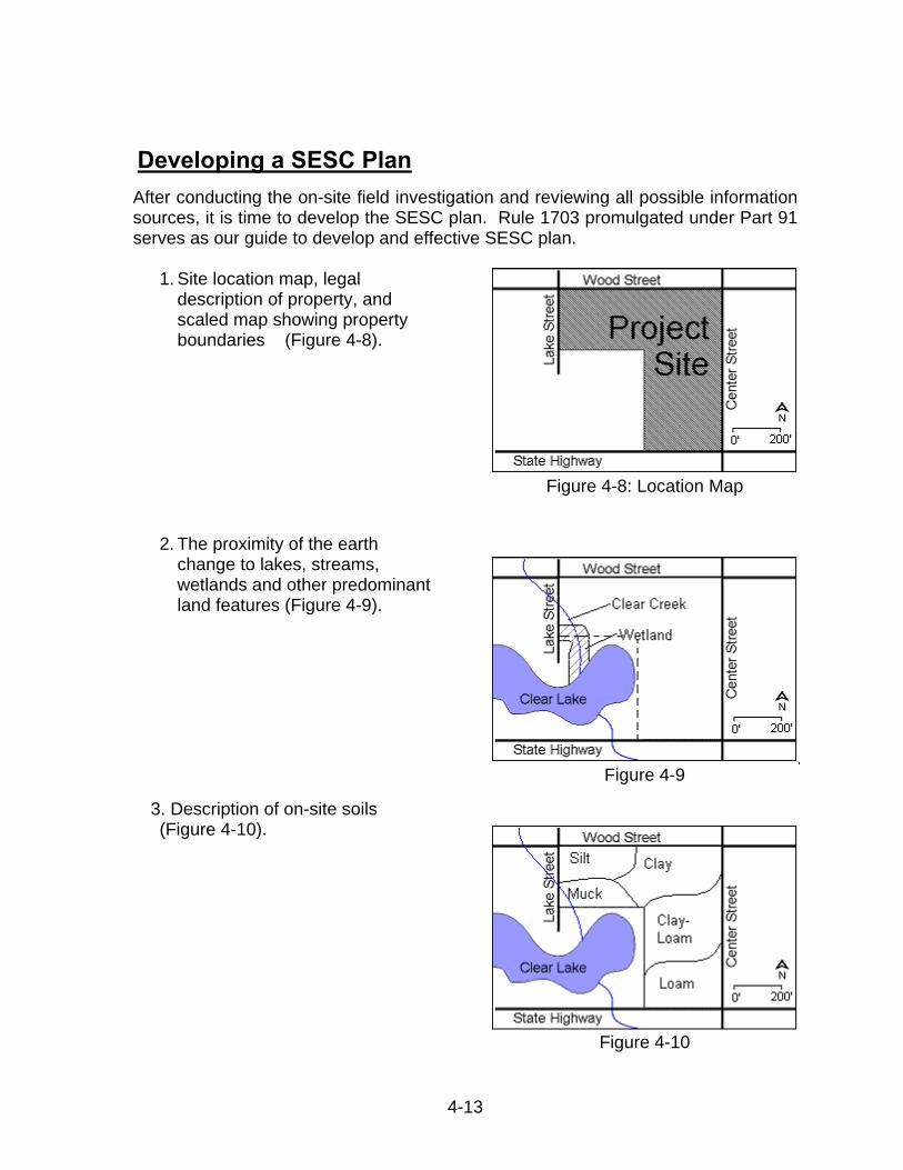
Developing a SESC Plan After conducting the on-site field investigation and reviewing all possible information sources, it is time to develop the SESC plan. Rule 1703 promulgated under Part 91 serves as our guide to develop and effective SESC plan.
1. Site location map, legal
description of property, and scaled map showing property boundaries (Figure 4-8).
2. The proximity of the earth change to lakes, streams, wetlands and other predominant land features (Figure 4-9).
3. Description of on-site soils (Figure 4-10).
Figure 4-8: Location Map
Figure 4-9
Figure 4-10
4-13
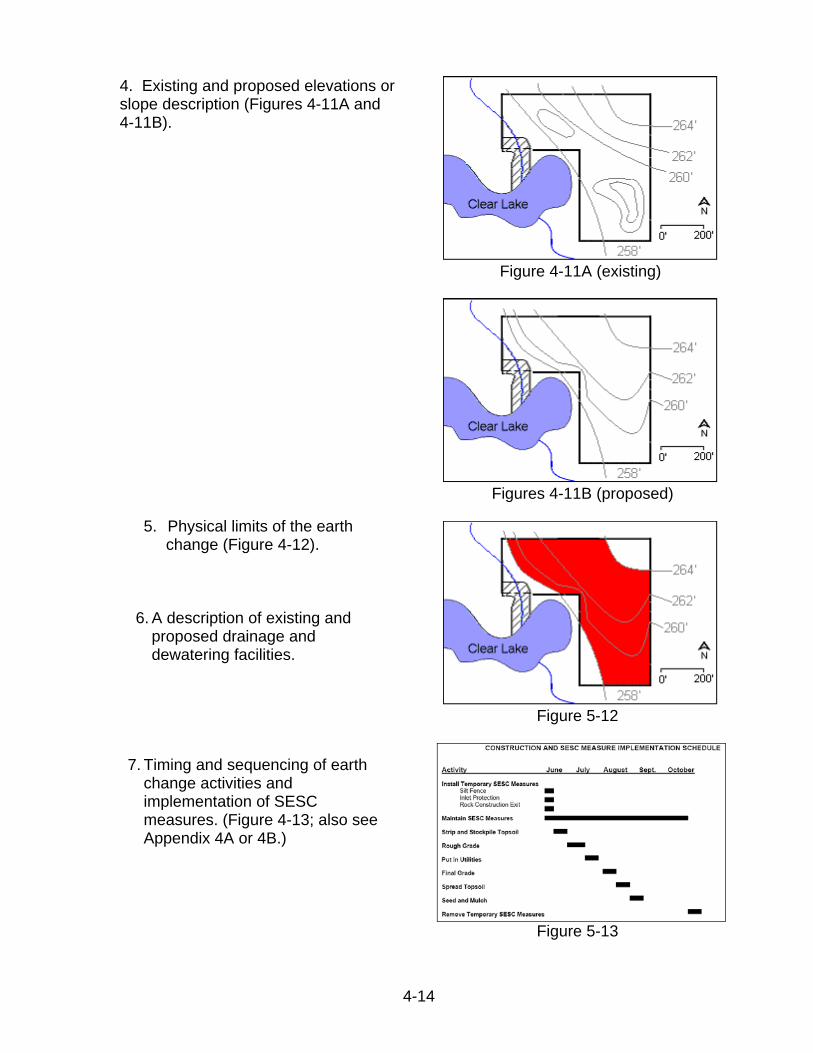
4. Existing and proposed elevations or slope description (Figures 4-11A and 4-11B).
5. Physical limits of the earth change (Figure 4-12).
6. A description of existing and proposed drainage and dewatering facilities.
7. Timing and sequencing of earth
change activities and implementation of SESC measures. (Figure 4-13; also see Appendix 4A or 4B.)
Figure 4-11A (existing)
Figures 4-11B (proposed)
Figure 5-12
Figure 5-13
4-14
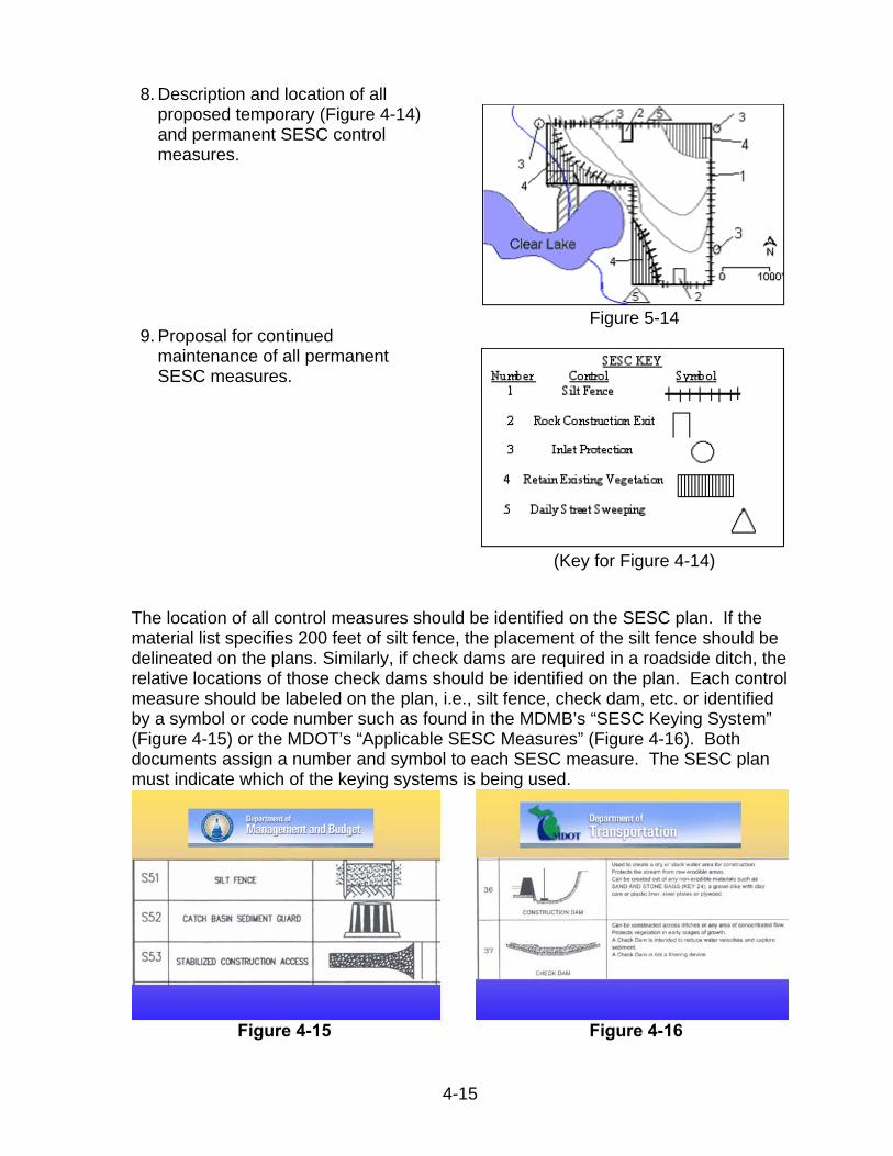
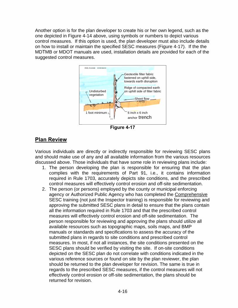
8. Description and location of all proposed temporary (Figure 4-14) and permanent SESC control measures.
9. Proposal for continued maintenance of all permanent SESC measures.
Figure 5-14
(Key for Figure 4-14)
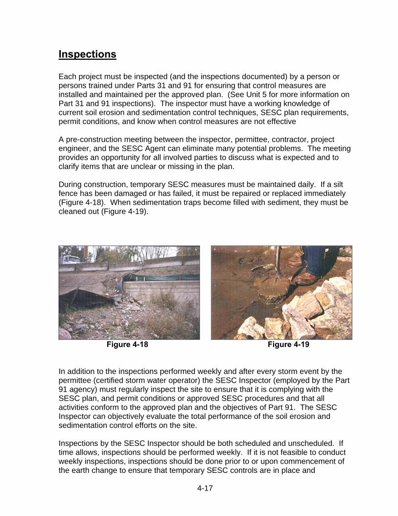
The location of all control measures should be identified on the SESC plan. If the material list specifies 200 feet of silt fence, the placement of the silt fence should be delineated on the plans. Similarly, if check dams are required in a roadside ditch, the relative locations of those check dams should be identified on the plan. Each control measure should be labeled on the plan, i.e., silt fence, check dam, etc. or identified by a symbol or code number such as found in the MDMB’s “SESC Keying System” (Figure 4-15) or the MDOT’s “Applicable SESC Measures” (Figure 4-16). Both documents assign a number and symbol to each SESC measure. The SESC plan must indicate which of the keying systems is being used.
Figure 4-15 Figure 4-16
4-15
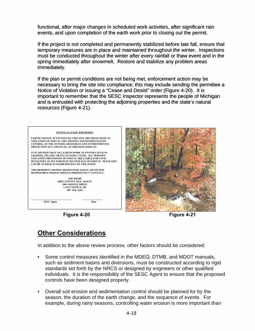
Another option is for the plan developer to create his or her own legend, such as the one depicted in Figure 4-14 above, using symbols or numbers to depict various control measures. If this option is used, the plan developer must also include details on how to install or maintain the specified SESC measures (Figure 4-17). If the the MDTMB or MDOT manuals are used, installation details are provided for each of the suggested control measures.
Geotextile filter fabric fastened on uphill side, towards earth disruption
Ridge of compacted earth on uphill side of filter fabric Undisturbed
vegetationSheet flow
4-16
Figure 4-17
Plan Review
Various individuals are directly or indirectly responsible for reviewing SESC plans and should make use of any and all available information from the various resources discussed above. Those individuals that have some role in reviewing plans include:
1. The person developing the plan is responsible for ensuring that the plancomplies with the requirements of Part 91, i.e., it contains informationrequired in Rule 1703, accurately depicts site conditions, and the prescribedcontrol measures will effectively control erosion and off-site sedimentation.
2. The person (or persons) employed by the county or municipal enforcingagency or Authorized Public Agency who has completed the ComprehensiveSESC training (not just the Inspector training) is responsible for reviewing andapproving the submitted SESC plans in detail to ensure that the plans containall the information required in Rule 1703 and that the prescribed controlmeasures will effectively control erosion and off-site sedimentation. Theperson responsible for reviewing and approving the plans should utilize allavailable resources such as topographic maps, soils maps, and BMPmanuals or standards and specifications to assess the accuracy of thesubmitted plans in regards to site conditions and prescribed controlmeasures. In most, if not all instances, the site conditions presented on theSESC plans should be verified by visiting the site. If on-site conditionsdepicted on the SESC plan do not correlate with conditions indicated in thevarious reference sources or found on site by the plan reviewer, the planshould be returned to the plan developer for revision. The same is true inregards to the prescribed SESC measures, if the control measures will noteffectively control erosion or off-site sedimentation, the plans should bereturned for revision.
6 inch x 6 inch anchor trench
1 foot minimum
Inspections Each project must be inspected (and the inspections documented) by a person or persons trained under Parts 31 and 91 for ensuring that control measures are installed and maintained per the approved plan. (See Unit 5 for more information on Part 31 and 91 inspections). The inspector must have a working knowledge of current soil erosion and sedimentation control techniques, SESC plan requirements, permit conditions, and know when control measures are not effective A pre-construction meeting between the inspector, permittee, contractor, project engineer, and the SESC Agent can eliminate many potential problems. The meeting provides an opportunity for all involved parties to discuss what is expected and to clarify items that are unclear or missing in the plan. During construction, temporary SESC measures must be maintained daily. If a silt fence has been damaged or has failed, it must be repaired or replaced immediately (Figure 4-18). When sedimentation traps become filled with sediment, they must be cleaned out (Figure 4-19).
Figure 4-18
Figure 4-19
In addition to the inspections performed weekly and after every storm event by the permittee (certified storm water operator) the SESC Inspector (employed by the Part 91 agency) must regularly inspect the site to ensure that it is complying with the SESC plan, and permit conditions or approved SESC procedures and that all activities conform to the approved plan and the objectives of Part 91. The SESC Inspector can objectively evaluate the total performance of the soil erosion and sedimentation control efforts on the site. Inspections by the SESC Inspector should be both scheduled and unscheduled. If time allows, inspections should be performed weekly. If it is not feasible to conduct weekly inspections, inspections should be done prior to or upon commencement of the earth change to ensure that temporary SESC controls are in place and
4-17
functional, after major changes in scheduled work activities, after significant rain events, and upon completion of the earth work prior to closing out the permit. functional, after major changes in scheduled work activities, after significant rain events, and upon completion of the earth work prior to closing out the permit.
If the project is not completed and permanently stabilized before late fall, ensure that temporary measures are in place and maintained throughout the winter. Inspections must be conducted throughout the winter after every rainfall or thaw event and in the spring immediately after snowmelt. Restore and stabilize any problem areas immediately.
If the project is not completed and permanently stabilized before late fall, ensure that temporary measures are in place and maintained throughout the winter. Inspections must be conducted throughout the winter after every rainfall or thaw event and in the spring immediately after snowmelt. Restore and stabilize any problem areas immediately.
If the plan or permit conditions are not being met, enforcement action may be necessary to bring the site into compliance; this may include sending the permittee a If the plan or permit conditions are not being met, enforcement action may be necessary to bring the site into compliance; this may include sending the permittee a Notice of Violation or issuing a “Cease and Desist” order (Figure 4-20). It is important to remember that the SESC Inspector represents the people of Michigan and is entrusted with protecting the adjoining properties and the state’s natural resources (Figure 4-21).
Notice of Violation or issuing a “Cease and Desist” order (Figure 4-20). It is important to remember that the SESC Inspector represents the people of Michigan and is entrusted with protecting the adjoining properties and the state’s natural resources (Figure 4-21).
NOTICE to CEASE AND DESIST
EARTH CHANGE ACTIVITIES ON THIS SITE ARE BEING DONE IN VIOLATION OF PART 91, SOIL EROSION AND SEDIMENTATION CONTROL, OF THE NATURAL RESOURCES AND ENVIRONMENTAL PROTECTION ACT, 1994 PA 451, AS AMENDED (PART 91)
IT IS ADVISED THAT ALL EARTH WORK ACTIVITIES SUCH AS GRADING, FILLING OR EXCAVATING CEASE. ALL PERSONS VIOLATING PROVISIONS OF PART 91 ARE LIABLE FOR CIVIL PENALITIES AS SET FORTH IN SECTION 9121 OF PART 91. PENALTIES CAN BE AS HIGH AS $25,000 PER DAY OF VIOLATION.
THE PROPERTY OWNER, DESIGNATED AGENT, OR ON-SITE RESPONSIBLE PERSON SHOULD IMMEDIATELY CONTACT:
JOE MUDD DIRT COUNTY SESC AGENT
1001 GRAVEL DRIVE LAST CHANCE, MI
987- 654- 3210
_________________________________ ________________ SESC Agent Date
Figure 4-20 Figure 4-21
Other Considerations In addition to the above review process, other factors should be considered:
• Some control measures identified in the MDEQ, DTMB, and MDOT manuals, such as sediment basins and diversions, must be constructed according to rigid standards set forth by the NRCS or designed by engineers or other qualified individuals. It is the responsibility of the SESC Agent to ensure that the proposed controls have been designed properly.
• Overall soil erosion and sedimentation control should be planned for by the season, the duration of the earth change, and the sequence of events. For example, during rainy seasons, controlling water erosion is more important than
4-18
4-19
during dry periods, and must be planned for accordingly. In contrast, more emphasis must be placed on preventing wind erosion during the dry season.
• Be certain that adequate soil erosion and sedimentation control measures are
installed and maintained for all earth change areas. The controls must minimize on-site erosion, off-site sedimentation, and reduce all runoff leaving the site to non-erosive velocities.
• Temporary control measures should be installed and functional prior to starting
the earth change. Permanent measures should be installed as early as possible in the construction schedule but always within 5 days after reaching final grade. . This involves stabilizing "small" areas as they are completed, instead of waiting until all construction is completed before installing permanent controls.
Summary No single source of information is likely to contain all the data needed to develop or evaluate a proposed soil erosion and sedimentation control plan. Information from several sources such as the USGS topographic maps, site-specific topographic maps, county soil surveys, and aerial photographs must be examined and verified through site inspection. Site inspections will help the plan developer and the reviewer get a “feel” for the site and can be used as a opportunity to identify potential problem areas and choose specific control measures. Effective administration of the county or local program is critical for controlling soil erosion and off-site sedimentation resulting from earth change activities. It documents the basic process by which soil erosion and sedimentation control is addressed in a logical and systematic sequence. The SESC Agent's responsibility is to assure consistent program administration and compliance with Part 91. A clear understanding of these roles and responsibilities is necessary in developing a successful permit issuance system. The permit issued by the SESC Agent to the permittee is a legal document which authorizes an earth change, provided that the soil erosion and sedimentation control plan is followed. In the end, the burden for protecting the environment and the control of soil erosion and sedimentation is placed on the permittee. In summary it is important to remember that effective erosion and sedimentation control begins with a carefully developed soil erosion and sedimentation control plan. An effective plan results from a thorough site planning process. The first two steps of site planning are the:
• Inventory • Analysis
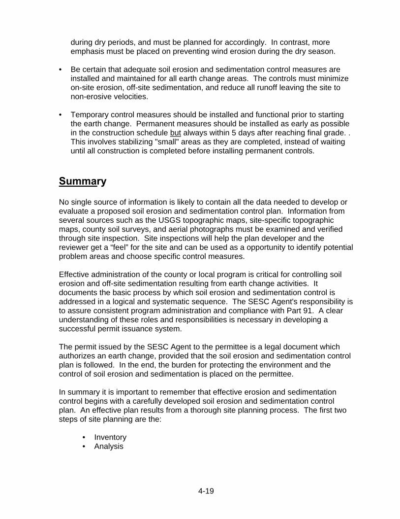
The inventory includes mapping soils, topography, vegetation, and drainage information. Analysis is the interpretation of how that information will influence soil erosion and sedimentation control. Key people responsible for preventing erosion and off-site sedimentation are:
• Planner or designer who develops the site plan and the soil erosion and sedimentation control plan (Figure 4-22)
Figure 4-22
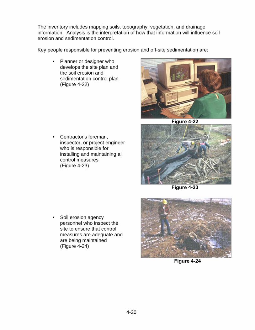
• Contractor's foreman,
inspector, or project engineer who is responsible for installing and maintaining all control measures (Figure 4-23)
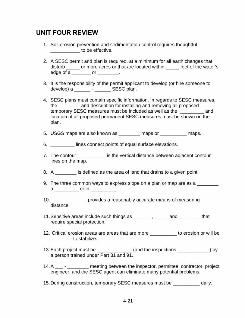
• Soil erosion agency personnel who inspect the site to ensure that control measures are adequate and are being maintained (Figure 4-24)
Figure 4-23
Figure 4-24
4-20
4-21
UNIT FOUR REVIEW
1. Soil erosion prevention and sedimentation control requires thoughtful ___________ to be effective.
2. A SESC permit and plan is required, at a minimum for all earth changes that
disturb _____ or more acres or that are located within _____ feet of the water’s edge of a _______ or ________.
3. It is the responsibility of the permit applicant to develop (or hire someone to
develop) a ______ - ______ SESC plan.
4. SESC plans must contain specific information. In regards to SESC measures, the ________ and description for installing and removing all proposed temporary SESC measures must be included as well as the _________ and location of all proposed permanent SESC measures must be shown on the plan.
5. USGS maps are also known as ________ maps or __________ maps.
6. _________ lines connect points of equal surface elevations.
7. The contour __________ is the vertical distance between adjacent contour
lines on the map.
8. A ________ is defined as the area of land that drains to a given point.
9. The three common ways to express slope on a plan or map are as a ________, a _________ or in __________.
10. _____________ provides a reasonably accurate means of measuring
distance.
11. Sensitive areas include such things as _______, _____ and ________ that require special protection.
12. Critical erosion areas are areas that are more __________ to erosion or will be
________ to stabilize.
13. Each project must be _____________ (and the inspections ____________) by a person trained under Part 31 and 91.
14. A ___ - ________ meeting between the inspector, permittee, contractor, project
engineer, and the SESC agent can eliminate many potential problems.
15. During construction, temporary SESC measures must be __________ daily.

16. Inspections by the SESC inspector should be both ____________ and
________.
17. If the project is not completed and permanently stabilized before fall, ensure that _______________ measures are in place and _________ throughout the winter.
18. SESC controls must minimize on-site _________, off-site _________, and
reduce all __________ leaving the site to ____-______ velocities.
19. Temporary control measures should be ___________ and __________ prior to starting the earth change.
20. Permanent control measures should be installed as early as _______ in the
construction schedule and always with ___ days after reaching final grade.
4-22
ANSWERS TO UNIT FOUR REVIEW
1. Soil erosion prevention and sedimentation control requires thoughtful planning to be effective.
2. A SESC permit and plan is required, at a minimum for all earth changes that
disturb one or more acres or that are located within 500 feet of the water’s edge of a lake or stream.
3. It is the responsibility of the permit applicant to develop (or hire someone to
develop) a site-specific SESC plan.
4. SESC plans must contain specific information. In regards to SESC measures, the location and description for installing and removing all proposed temporary SESC measures must be included as well as the description and location of all proposed permanent SESC measures must be shown on the plan.
5. USGS maps are also known as quadrangle maps or topographic maps.
6. Contour lines connect points of equal surface elevations.
7. The contour interval is the vertical distance between adjacent contour lines on
the map.
8. A watershed is defined as the area of land that drains to a given point.
9. The three common ways to express slope on a plan or map are as a ratio, a percent, or in degrees.
10. Pacing provides a reasonably accurate means of measuring distance.
11. Sensitive areas include such things as lakes, streams, and wetlands that
require special protection.
12. Critical erosion areas are areas that are more susceptible to erosion or will be difficult to stabilize.
13. Each project must be inspected (and the inspections documented) by a
person trained under Part 31 and 91.
14. A pre-construction meeting between the inspector, permittee, contractor, project engineer, and the SESC agent can eliminate many potential problems.
15. During construction, temporary SESC measures must be maintained daily.
4-23

4-24
16. Inspections by the SESC inspector should be both scheduled and unscheduled.
17. If the project is not completed and permanently stabilized before fall, ensure
that temporary measures are in place and inspected throughout the winter.
18. SESC controls must minimize on-site erosion, off-site sedimentation, and reduce all runoff leaving the site to non-erosive velocities.
19. Temporary control measures should be installed and functional prior to
starting the earth change.
20. Permanent control measures should be installed as early as possible in the construction schedule and always with 5 days after reaching final grade.
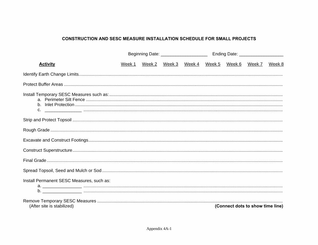
CONSTRUCTION AND SESC MEASURE INSTALLATION SCHEDULE FOR SMALL PROJECTS Beginning Date: ___________________ Ending Date: __________________ Activity Week 1 Week 2 Week 3 Week 4 Week 5 Week 6 Week 7 Week 8 Identify Earth Change Limits...................................................................................................................................................................... Protect Buffer Areas .................................................................................................................................................................................. Install Temporary SESC Measures such as: .............................................................................................................................................
a. Perimeter Silt Fence ................................................................................................................................................................ b. Inlet Protection ......................................................................................................................................................................... c. _______________ ..................................................................................................................................................................
Strip and Protect Topsoil ........................................................................................................................................................................... Rough Grade ............................................................................................................................................................................................. Excavate and Construct Footings.............................................................................................................................................................. Construct Superstructure........................................................................................................................................................................... Final Grade................................................................................................................................................................................................ Spread Topsoil, Seed and Mulch or Sod................................................................................................................................................... Install Permanent SESC Measures, such as:
a. ________________ .................................................................................................................................................................. b. ________________ ..................................................................................................................................................................
Remove Temporary SESC Measures ....................................................................................................................................................... (After site is stabilized) (Connect dots to show time line)
Appendix 4A-1
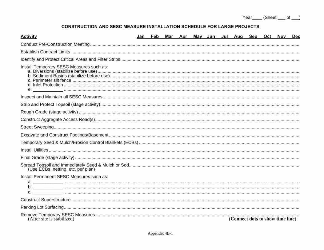
Year____ (Sheet ___ of ___)
CONSTRUCTION AND SESC MEASURE INSTALLATION SCHEDULE FOR LARGE PROJECTS
Activity Jan Feb Mar Apr May Jun Jul Aug Sep Oct Nov Dec Conduct Pre-Construction Meeting........................................................................................................................................................................ Establish Contract Limits ....................................................................................................................................................................................... Identify and Protect Critical Areas and Filter Strips................................................................................................................................................ Install Temporary SESC Measures such as:
a. Diversions (stabilize before use) .................................................................................................................................................................. b. Sediment Basins (stabilize before use)........................................................................................................................................................ c. Perimeter silt fence....................................................................................................................................................................................... d. Inlet Protection ............................................................................................................................................................................................. e. ____________ .............................................................................................................................................................................................
Inspect and Maintain all SESC Measures.............................................................................................................................................................. Strip and Protect Topsoil (stage activity)................................................................................................................................................................ Rough Grade (stage activity) ................................................................................................................................................................................. Construct Aggregate Access Road(s).................................................................................................................................................................... Street Sweeping..................................................................................................................................................................................................... Excavate and Construct Footings/Basement ......................................................................................................................................................... Temporary Seed & Mulch/Erosion Control Blankets (ECBs) ................................................................................................................................. Install Utilities ......................................................................................................................................................................................................... Final Grade (stage activity) .................................................................................................................................................................................... Spread Topsoil and Immediately Seed & Mulch or Sod.........................................................................................................................................
(Use ECBs, netting, etc. per plan) Install Permanent SESC Measures such as:
a. ____________ ............................................................................................................................................................................................ b. ____________ ............................................................................................................................................................................................ c. ____________ ............................................................................................................................................................................................
Construct Superstructure ....................................................................................................................................................................................... Parking Lot Surfacing............................................................................................................................................................................................. Remove Temporary SESC Measures....................................................................................................................................................................
(After site is stabilized) (Connect dots to show time line)
Appendix 4B-1