UNIT - 3 Software Designgvpcew.ac.in/LN-CSE-IT-22-32/CSE-IT/3-Year/32-SE/SE-KNSC-UNIT-3.pdf · For...
37
UNIT - 3 Software Design Definition Software design is the process by which an agent creates a specification of a software artifact, intended to accomplish goals, using a set of primitive components and subject to constraints. A software product is considered a collection of software modules. A module is a part of a software product which has data and functions together and an interface with other modules to produce some outcome. For Example: A banking S/W system consists of various modules like ATM interface, online transaction, loan management, deposit, and so on. Each of these module interacts with other modules to accomplish the banking activities. For assessing user requirements, an SRS (Software Requirement Specification) document is created whereas for coding and implementation, there is a need of more specific and detailed requirements in software terms. The output of this process can directly be used into implementation in programming languages. Software design is the first step in SDLC (Software Design Life Cycle), which moves the concentration from problem domain to solution domain. It tries to specify how to fulfil the requirements mentioned in SRS. Software Design Process It exists between Requirements engineering and programming. Software design yields three levels of results: Architectural Design - The architectural design is the highest abstract version of the system. It identifies the software as a system with many components interacting with each other. At this level, the designers get the idea of proposed solution domain. The external design considers the architectural aspects related to business, technology, major data stores, and structure of the product. High Level Design (Physical Design) - The high-level design breaks the ‘single entity- multiple component’ concept of architectural design(conceptual view) into less-abstracted view of sub-systems and modules and depicts their interaction with each other. High-level design focuses on how the system along with all of its components can be implemented in forms of modules. It recognizes modular structure of each sub-system and their relation and interaction among each other. Detailed Design- Detailed design deals with the implementation part of what is seen as a system and its sub-systems in the previous two designs. It is more detailed towards modules and their implementations. It defines logical structure of each module and their interfaces to communicate with other modules.
Transcript of UNIT - 3 Software Designgvpcew.ac.in/LN-CSE-IT-22-32/CSE-IT/3-Year/32-SE/SE-KNSC-UNIT-3.pdf · For...

UNIT - 3 Software Design
Definition
Software design is the process by which an agent creates a specification of
a software artifact, intended to accomplish goals, using a set of primitive components and subject to constraints.
A software product is considered a collection of software modules. A module is a part of a
software product which has data and functions together and an interface with other modules to
produce some outcome.
For Example: A banking S/W system consists of various modules like ATM interface, online
transaction, loan management, deposit, and so on. Each of these module interacts with other modules to accomplish the banking activities.
For assessing user requirements, an SRS (Software Requirement Specification) document is created whereas for coding and implementation, there is a need of more specific and detailed
requirements in software terms. The output of this process can directly be used into implementation
in programming languages.
Software design is the first step in SDLC (Software Design Life Cycle), which moves the
concentration from problem domain to solution domain. It tries to specify how to fulfil the
requirements mentioned in SRS.
Software Design Process It exists between Requirements engineering and programming. Software design yields three
levels of results:
Architectural Design - The architectural design is the highest abstract version of the system.
It identifies the software as a system with many components interacting with each other. At
this level, the designers get the idea of proposed solution domain. The external design considers the architectural aspects related to business, technology, major data stores, and structure of the product.
High Level Design (Physical Design) - The high-level design breaks the ‘single entity-
multiple component’ concept of architectural design(conceptual view) into less-abstracted
view of sub-systems and modules and depicts their interaction with each other. High-level
design focuses on how the system along with all of its components can be implemented in forms of modules. It recognizes modular structure of each sub-system and their relation and interaction among each other.
Detailed Design- Detailed design deals with the implementation part of what is seen as a
system and its sub-systems in the previous two designs. It is more detailed towards modules
and their implementations. It defines logical structure of each module and their interfaces to communicate with other modules.

Characteristics of good software design: The quality of a software design can be characterized by the application domain. For example real
time software will focus more on efficiency and reliability issues whereas academic automation s/w
will concentrate on understandability and usability issues. A designer always tries to produce a good design. The desirable characteristics that a good s/w design should have are as follows:
1. Correctness: A design is said to be correct if it is correctly produced according to the stated
requirements of customers in the SRS. It should fulfil all the functional features, satisfy constraints, and follow the guidelines. A correct design is more likely to produce accurate
outcomes.
2. Efficiency: It is concerned with performance related issues; for example, optimal utilization
of resources. The design should consume less memory and processor time. Software design and its implementation should be as fast as requires by the user.
3. Understandability: It should be easy to understand what the module is, how it is connected to
other modules, what data structure is used, and its flow of information. Documentation of a design can also make it more understandable. An understandable design will make the
maintenance and implementation tasks easier.
4. Maintainability: A difficult and complex design would take a larger time to be understood and modified. Therefore, the design should be easy to be modified, should include new features,
should not have unnecessary parts, and it should be easy to migrate it onto another platform.
5. Simplicity: A simple design will improve understandability and maintainability. Introducing a
simple design is rare because a design follows certain steps and criteria. Still designers always think to “keep it simple” rather than “make it complex”.
6. Completeness: It means that the design includes all the specifications of the SRS. A complete
design may not necessarily be correct. But a correct design can be complete. 7. Verifiability: The design should be able to be verified against the requirements documents
and programs. Interfaces between the modules are necessary for integration and function
prototyping. 8. Portability: The external design mainly focuses on the interface, business, and technology
architectures. These architectures must be able to move a design to another environment. This
may be required when the system is to be migrated onto different platforms.
9. Modularity: A modular design will be easy to understand and modify. Once a modular system is designed, it allows easy development and repairing of required modules independently.
10. Reliability: This factor depends on the measurement of completeness, consistency, and
robustness in the software design. Nowadays, most people depend and rely on S/W to always work and yield correct results. If there is any unreliable part of software, it can cause major
dangers.
11. Reusability: The software design should be standard and generic so that it can be used for
mass production of quality products with small cycle time and reduced cost. The object code, classes, design patterns, packages, etc., are the reusable parts of software.

Design Principles:
Every software process is characterized by basic concepts along with certain practices or methods.
Methods represent the manner through which the concepts are applied. As new technology replaces
older technology, many changes occur in the methods that are used to apply the concepts for the
development of software. However, the fundamental concepts underlining the software design process
remain the same, some of which are described here.
1. Abstraction
Abstraction refers to a powerful design tool, which allows software designers to consider components at an abstract level, while neglecting the implementation details of the
components. IEEE defines abstraction as 'a view of a problem that extracts the
essential information relevant to a particular purpose and ignores the remainder of the
information.' The concept of abstraction can be used in two ways: as a process and as an entity. As a process, it refers to a mechanism of hiding irrelevant details and representing only the essential
features of an item so that one can focus on important things at a time. As an entity, it refers to a
model or view of an item.
Each step in the software process is accomplished through various levels of abstraction. At
the highest level, an outline of the solution to the problem is presented whereas at the lower levels, the
solution to the problem is presented in detail. For example, in the requirements analysis phase, a solution to the problem is presented using the language of problem environment and as we proceed
through the software process, the abstraction level reduces and at the lowest level, source code of the
software is produced.
There are three commonly used abstraction mechanisms in software design namely, functional abstraction, data abstraction and control abstraction. All these mechanisms allow us to
control the complexity of the design process by proceeding from the abstract design model to concrete
design model in a systematic manner.
1. Functional abstraction: This involves the use of parameterized subprograms. Functional abstraction
can be generalized as collections of subprograms referred to as 'groups'. Within these groups there
exist routines which may be visible or hidden. Visible routines can be used within the containing groups as well as within other groups, whereas hidden routines are hidden from other groups and can
be used within the containing group only.
2. Data abstraction: This involves specifying data that describes a data object. For example, the data
object window encompasses a set of attributes (window type, window dimension) that describe the window object clearly. In this abstraction mechanism, representation and manipulation details are
ignored.
3. Control abstraction: This states the desired effect, without stating the exact mechanism of control. For example, if and while statements in programming languages (like C and C++) are abstractions of
machine code implementations, which involve conditional instructions. In the architectural design
level, this abstraction mechanism permits specifications of sequential subprogram and exception
handlers without the concern for exact details of implementation.
2. Architecture
Software architecture refers to the structure of the system, which is composed of various
components of a program/ system, the attributes (properties) of those components and the relationship amongst them. The software architecture enables the software engineers to analyze the software
design efficiently. In addition, it also helps them in decision-making and handling risks. The software
architecture does the following.
Provides an insight to all the interested stakeholders that enable them to communicate with each other
Highlights early design decisions, which have great impact on the software engineering activities
(like coding and testing) that follow the design phase

Creates intellectual models of how the system is organized into components and how these
components interact with each other.
Currently, software architecture is represented in an informal and unplanned manner. Though
the architectural concepts are often represented in the infrastructure (for supporting particular
architectural styles) and the initial stages of a system configuration, the lack of an explicit
independent characterization of architecture restricts the advantages of this design concept in the
present scenario.
Note that software architecture comprises two elements of design model, namely, data design
and architectural design.
3. Patterns
A pattern provides a description of the solution to a recurring design problem of some specific
domain in such a way that the solution can be used again and again. The objective of each pattern is to
provide an insight to a designer who can determine the following.
1. Whether the pattern can be reused
2. Whether the pattern is applicable to the current project
3. Whether the pattern can be used to develop a similar but functionally or structurally different design pattern.
Types of Design Patterns
Software engineer can use the design pattern during the entire software design process. When the analysis model is developed, the designer can examine the problem
description at different levels of abstraction to determine whether it complies with one or
more of the following types of design patterns.
1. Architectural patterns: These patterns are high-level strategies that refer to the overall structure and organization of a software system. That is, they define the elements of a
software system such as subsystems, components, classes, etc. In addition, they also indicate
the relationship between the elements along with the rules and guidelines for specifying these relationships. Note that architectural patterns are often considered equivalent to software
architecture.
2. Design patterns: These patterns are medium-level strategies that are used to solve design problems. They provide a means for the refinement of the elements (as defined by
architectural pattern) of a software system or the relationship among them. Specific design
elements such as relationship among components or mechanisms that affect component-to-
component interaction are addressed by design patterns. Note that design patterns are often considered equivalent to software components.
3. Idioms: These patterns are low-level patterns, which are programming-language
specific. They describe the implementation of a software component, the method used for interaction among software components, etc., in a specific programming language. Note that
idioms are often termed as coding patterns.
4. Modularity: Modularity is achieved by dividing the software into uniquely named and addressable components, which are also known as modules. A complex system (large
program) is partitioned into a set of discrete modules in such a way that each module can be
developed independent of other modules. After developing the modules, they are integrated
together to meet the software requirements. Note that larger the number of modules a system
is divided into, greater will be the effort required to integrate the modules.
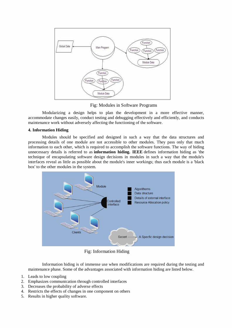
Fig: Modules in Software Programs
Modularizing a design helps to plan the development in a more effective manner,
accommodate changes easily, conduct testing and debugging effectively and efficiently, and conducts
maintenance work without adversely affecting the functioning of the software.
4. Information Hiding
Modules should be specified and designed in such a way that the data structures and
processing details of one module are not accessible to other modules. They pass only that much information to each other, which is required to accomplish the software functions. The way of hiding
unnecessary details is referred to as information hiding. IEEE defines information hiding as 'the
technique of encapsulating software design decisions in modules in such a way that the module's
interfaces reveal as little as possible about the module's inner workings; thus each module is a 'black
box' to the other modules in the system.
Fig: Information Hiding
Information hiding is of immense use when modifications are required during the testing and
maintenance phase. Some of the advantages associated with information hiding are listed below.
1. Leads to low coupling
2. Emphasizes communication through controlled interfaces
3. Decreases the probability of adverse effects 4. Restricts the effects of changes in one component on others
5. Results in higher quality software.

5. Stepwise Refinement
Stepwise refinement is a top-down design strategy used for decomposing a system from a
high level of abstraction into a more detailed level (lower level) of abstraction. At the highest level of
abstraction, function or information is defined conceptually without providing any information about
the internal workings of the function or internal structure of the data. As we proceed towards the
lower levels of abstraction, more and more details are available.
Software designers start the stepwise refinement process by creating a sequence of
compositions for the system being designed. Each composition is more detailed than the previous one and contains more components and interactions. The earlier compositions represent the significant
interactions within the system, while the later compositions show in detail how these interactions are
achieved.
To have a clear understanding of the concept, let us consider an example of stepwise
refinement. Every computer program comprises input, process, and output.
1. INPUT
Get user's name (string) through a prompt.
Get user's grade (integer from 0 to 100) through a prompt and validate.
2. PROCESS 3. OUTPUT
This is the first step in refinement. The input phase can be refined further as given here.
1. INPUT o Get user's name through a prompt.
o Get user's grade through a prompt.
o While (invalid grade)
Ask again:
2. PROCESS
3. OUTPUT
Note: Stepwise refinement can also be performed for PROCESS and OUTPUT phase.
6. Refactoring
Refactoring is an important design activity that reduces the complexity of module design
keeping its behaviour or function unchanged. Refactoring can be defined as a process of modifying a software system to improve the internal structure of design without changing its external behavior.
During the refactoring process, the existing design is checked for any type of flaws like redundancy,
poorly constructed algorithms and data structures, etc., in order to improve the design. For example, a
design model might yield a component which exhibits low cohesion (like a component performs four functions that have a limited relationship with one another). Software designers may decide to refactor
the component into four different components, each exhibiting high cohesion. This leads to easier
integration, testing, and maintenance of the software components.
7. Structural Partitioning
When the architectural style of a design follows a hierarchical nature, the structure of the
program can be partitioned either horizontally or vertically. In horizontal partitioning, the control
modules are used to communicate between functions and execute the functions. Structural partitioning
provides the following benefits.
The testing and maintenance of software becomes easier.
The negative impacts spread slowly.
The software can be extended easily.

Besides these advantages, horizontal partitioning has some disadvantage also. It requires passing more data across the module interface, which makes the control flow of the problem more
complex. This usually happens in cases where data moves rapidly from one function to another.
In vertical partitioning, the functionality is distributed among the modules--in a top-down
manner. The modules at the top level called control modules perform the decision-making and do little processing whereas the modules at the low level called worker modules perform all input,
computation and output tasks.
8. Concurrency
Computer has limited resources and they must be utilized efficiently as much as possible. To
utilize these resources efficiently, multiple tasks must be executed concurrently. This requirement
makes concurrency one of the major concepts of software design. Every system must be designed to allow multiple processes to execute concurrently, whenever possible. For example, if the current
process is waiting for some event to occur, the system must execute some other process in the mean
time.
However, concurrent execution of multiple processes sometimes may result in undesirable situations such as an inconsistent state, deadlock, etc. For example, consider two processes A and B
and a data item Q1 with the value '200'. Further, suppose A and B are being executed concurrently
and firstly A reads the value of Q1 (which is '200') to add '100' to it. However, before A updates es the value of Q1, B reads the value ofQ1 (which is still '200') to add '50' to it. In this situation, whether A
or B first updates the value of Q1, the value of would definitely be wrong resulting in an inconsistent
state of the system. This is because the actions of A and B are not synchronized with each other. Thus,
the system must control the concurrent execution and synchronize the actions of concurrent processes.
One way to achieve synchronization is mutual exclusion, which ensures that two concurrent
processes do not interfere with the actions of each other. To ensure this, mutual exclusion may use
locking technique. In this technique, the processes need to lock the data item to be read or updated. The data item locked by some process cannot be accessed by other processes until it is unlocked. It
implies that the process, that needs to access the data item locked by some other process, has to wait.
Modular Design:
A modular design focuses on minimizing the interconnection b/w modules. In a modular
design, several independent and executable modules are composed together to construct an executable application program. The programming language support, interfaces, and the information hiding
principles ensure modular system design. There are various modularization criterions to measure the
modularity of a system. The most common criterions are functional independency; levels of abstraction; information hiding; functional diagrams, such as DFD, modular programming languages,
coupling, and cohesion. An effective modular system has low coupling and high cohesion. So, coupling and cohesion are most popular criterions used to measure the modularity in a system.

1. Coupling:
Coupling between two modules is a measure of the degree of interdependence or interaction
between the two modules. A module having high cohesion and low coupling is said to be functionally
independent of other modules. If two modules interchange large amounts of data, then they are highly
interdependent. The degree of coupling between two modules depends on their interface complexity. The interface complexity is basically determined by the number of types of parameters that are
interchanged while invoking the functions of the module. Module coupling can be Tightly or Loosely
coupled based on the dependencies.
Fig: Module Coupling
Classification of Coupling:
Even if there are no techniques to precisely and quantitatively estimate the coupling between
two modules, classification of the different types of coupling will help to quantitatively estimate the degree of coupling between two modules. Six types of coupling can occur between any two modules.
This is shown in the figure given below:
Fig: Types of Coupling
i) Data coupling: Two modules are data coupled, if they communicate through a parameter. An
example is an elementary data item passed as a parameter between two modules, e.g. an integer, a
float, a character, etc. This data item should be problem related and not used for the control purpose.
ii) Stamp coupling: Two modules are stamp coupled, if they communicate using a composite data
item such as a record in PASCAL or a structure in C.
iii) Control coupling: Control coupling exists between two modules, if data from one module is used
to direct the order of instructions execution in another. An example of control coupling is a flag set in
one module and tested in another module.
iv) External Coupling: It occurs when two modules share an externally imposed data format,
communication protocol, or device interface. All the modules share the same I/O device or the
external environment.
v) Common coupling: Two modules are common coupled, if they share data through some global
data items.
vi) Content coupling: Content coupling exists between two modules, if they share code, e.g. a branch
from one module into another module.

2. Cohesion
Most researchers and engineers agree that a good software design implies clean
decomposition of the problem into modules, and the neat arrangement of these modules in a
hierarchy. The primary characteristics of neat module decomposition are high cohesion and low coupling. Cohesion is a measure of functional strength of a module. A module having high cohesion
and low coupling is said to be functionally independent of other modules. By the term functional
independence, we mean that a cohesive module performs a single task or function. A functionally
independent module has minimal interaction with other modules.
Classification of cohesion:
The different classes of cohesion that a module may possess are depicted in fig. given below:
Fig: Types of Cohesion
i) Coincidental cohesion: A module is said to have coincidental cohesion, if it performs a set of tasks
that relate to each other very loosely, if at all. In this case, the module contains a random collection of
functions. It is likely that the functions have been put in the module out of pure coincidence without
any thought or design. For example, in a transaction processing system (TPS), the get-input, print-error, and summarize-members functions are grouped into one module. The grouping does not have
any relevance to the structure of the problem.
ii) Logical cohesion: A module is said to be logically cohesive, if all elements of the module perform similar operations, e.g. error handling, data input, data output, etc. An example of logical cohesion is
the case where a set of print functions generating different output reports are arranged into a single
module.
iii) Temporal cohesion: When a module contains functions that are related by the fact that all the
functions must be executed in the same time span, the module is said to exhibit temporal cohesion.
The set of functions responsible for initialization, start-up, shutdown of some process, etc. exhibit
temporal cohesion.
iv) Procedural cohesion: A module is said to possess procedural cohesion, if the set of functions of
the module are all part of a procedure (algorithm) in which certain sequence of steps have to be
carried out for achieving an objective, e.g. the algorithm for decoding a message.
v) Communicational cohesion: A module is said to have communicational cohesion, if all functions
of the module refer to or update the same data structure, e.g. the set of functions defined on an array
or a stack.
vi) Sequential cohesion: A module is said to possess sequential cohesion, if the elements of a module
form the parts of sequence, where the output from one element of the sequence is input to the next.
For example, in a TPS, the get-input, validate-input, sort-input functions are grouped into one module.

vii) Functional cohesion: Functional cohesion is said to exist, if different elements of a module cooperate to achieve a single function. For example, a module containing all the functions required to
manage employees’ pay-roll exhibits functional cohesion. Suppose a module exhibits functional
cohesion and we are asked to describe what the module does, then we would be able to describe it
using a single sentence.
Design Methodologies:
A Design methodology provides the techniques and guidelines for the design process of a
system. There are different design processes for different design methodologies. The goal of all design methodologies is to produce a design for the solution of a system. A design process consists of
various design activities. The most popular design methodologies are:
1) Function Oriented Design
2) Object Oriented Design
1) Function Oriented Design:
The following are the salient features of a typical function-oriented design approach:
1. A system is viewed as something that performs a set of functions. Starting at this high-level view of the system, each function is successively refined into more detailed functions. For example, consider a
function create-new library-member which essentially creates the record for a new member, assigns a
unique membership number to him, and prints a bill towards his membership charge. This function
may consist of the following sub functions:
• Assign-membership-number
• Create-member-record
• Print-bill
Each of these sub-functions may be split into more detailed sub functions and so on.
2. The system state is centralized and shared among different functions, e.g. data such as member-
records is available for reference and updation to several functions such as:
• Create-new-member
• Delete-member
• Update-member-record
2) Object Oriented Design:
In the object-oriented design approach, the system is viewed as collection of objects (i.e.
entities). The state is decentralized among the objects and each object manages its own state
information. For example, in a Library Automation Software, each library member may be a separate object with its own data and functions to operate on these data. In fact, the functions defined for one
object cannot refer or change data of other objects. Objects have their own internal data which define
their state. Similar objects constitute a class. In other words, each object is a member of some class. Classes may inherit features from super class. Conceptually, objects communicate by message
passing.
Function-oriented vs. object-oriented design approach
The following are some of the important differences between function-oriented and object-
oriented design.
• Unlike function-oriented design methods, in OOD, the basic abstraction are not real-world functions
such as sort, display, track, etc, but realworld entities such as employee, picture, machine, radar system, etc. For example in OOD, an employee pay-roll software is not developed by designing
functions such as update-employee-record, getemployee-address, etc. but by designing objects such as

employees, departments, etc. Grady Booch sums up this difference as “identify verbs if you are after
procedural design and nouns if you are after object-oriented design”.
• In OOD, state information is not represented in a centralized shared memory but is distributed
among the objects of the system. For example, while developing an employee pay-roll system, the
employee data such as the names of the employees, their code numbers, basic salaries, etc. are usually implemented as global data in a traditional programming system; whereas in an object-oriented
system these data are distributed among different employee objects of the system. Objects
communicate by message passing. Therefore, one object may discover the state information of another object by interrogating it. Of course, somewhere or other the real-world functions must be
implemented. In OOD, the functions are usually associated with specific real-world entities (objects);
they directly access only part of the system state information.
• Function-oriented techniques such as SA/SD group functions together if, as a group, they constitute
a higher-level function. On the other hand, object-oriented techniques group functions together on the
basis of the data they operate on.
To illustrate the differences between the object-oriented and the function-oriented design approaches,
an example can be considered.
Example: Fire-Alarm System
The owner of a large multi-stored building wants to have a computerized fire alarm system for his building. Smoke detectors and fire alarms would be placed in each room of the building. The fire
alarm system would monitor the status of these smoke detectors. Whenever a fire condition is
reported by any of the smoke detectors, the fire alarm system should determine the location at which the fire condition is reported by any of the smoke detectors, the fire alarm system should determine
the location at which the fire condition has occurred and then sound the alarms only in the
neighbouring locations. The fire alarm system should also flash an alarm message on the computer
console. Fire fighting personnel man the console round the clock. After a fire condition has been successfully handled, the fire alarm system should support resetting the alarms by the fire fighting
personnel.
Function-Oriented Approach:
/* Global data (system state) accessible by various functions */
BOOL detector_status[MAX_ROOMS];
int detector_locs[MAX_ROOMS];
BOOL alarm_status[MAX_ROOMS];
/* alarm activated when status is set */
int alarm_locs[MAX_ROOMS];
/* room number where alarm is located */
int neighbor-alarm[MAX_ROOMS][10];
/* each detector has at most 10 neighboring locations */
The functions which operate on the system state are:
interrogate_detectors();
get_detector_location();
determine_neighbor();
ring_alarm();

reset_alarm();
report_fire_location();
Object-Oriented Approach:
class detector
attributes:
status, location, neighbours
operations: create, sense_status, get_location, find_neighbors
class alarm
attributes: location, status
operations: create, ring_alarm, get_location, reset_alarm
In the object oriented program, an appropriate number of instances of the class detector and alarm
should be created. If the function-oriented and the object-oriented programs are examined, it can be
seen that in the function-oriented program, the system state is centralized and several functions accessing this central data are defined. In case of the object-oriented program, the state information is
distributed among various sensor and alarm objects.
It is not necessary an object-oriented design be implemented by using an object-oriented language only. However, object-oriented languages such as C++ supports the definition of all the
basic mechanisms of class, inheritance, objects, methods, etc. and also support all key object-oriented
concepts that we have just discussed. Thus, an object-oriented language facilitates the implementation of an OOD. However, an OOD can as well be implemented using a conventional procedural language
– though it may require more effort to implement an OOD using a procedural language as compared
to the effort required for implementing the same design using an object-oriented language.
Even though object-oriented and function-oriented approaches are remarkably different approaches to software design, yet they do not replace each other but complement each other in some
sense. For example, usually one applies the top-down function-oriented techniques to design the
internal methods of a class, once the classes are identified. In this case, though outwardly the system appears to have been developed in an object-oriented fashion, but inside each class there may be a
small hierarchy of functions designed in a top-down manner.
Structured Design
Structured Design The aim of structured design is to transform the results of the structured
analysis (i.e. a DFD representation) into a structure chart. Structured design provides two strategies to
guide transformation of a DFD into a structure chart.
• Transform analysis
• Transaction analysis
Normally, one starts with the level 1 DFD, transforms it into module representation using either the transform or the transaction analysis and then proceeds towards the lower-level DFDs. At
each level of transformation, it is important to first determine whether the transform or the transaction
analysis is applicable to a particular DFD.

General Steps Involved in structured design are:
The type of data flow is established
In this step the nature of the data flowing between processes is defined.
Determine flow boundaries (switch points) This includes if the boundary is input boundary, output boundary, hub boundary or action
boundary or process.
Map the abstract DFD onto a particular program structure
Determine if the program structure is a transformational structure or transactional structure.
Define a valid control structure This step is also known as "first-level" factoring. It depends on whether transformational or
transactional models are used.
The control structure is either "Call-and-return" for transformational model or "Call-and-
act" for transactional model.
Refine (tune) the resulting structure This step is also known as "second-level factoring". It maps Input/Output flow
bounded parts of DFD.
Supplement and tune the final architectural structure
Apply basic module independence concepts (i.e. Explode or implode modules according to coupling/cohesion requirements) to obtain an easier implementation.
Structure Chart
A structure chart represents the software architecture, i.e. the various modules making up the
system, the dependency (which module calls which other modules), and the parameters that are
passed among the different modules. Hence, the structure chart representation can be easily implemented using some programming language. Since the main focus in a structure chart
representation is on the module structure of the software and the interactions among different
modules, the procedural aspects (e.g. how a particular functionality is achieved) are not represented.
The basic building blocks which are used to design structure charts are the following:
• Rectangular boxes: Represents a module.
• Module invocation arrows: Control is passed from one module to another module in the direction of
the connecting arrow.
• Data flow arrows: Arrows are annotated with data name; named data passes from one module to
another module in the direction of the arrow.
• Library modules: Represented by a rectangle with double edges.
• Selection: Represented by a diamond symbol.
• Repetition: Represented by a loop around the control flow arrow.
Structure Chart vs. Flow Chart
We are all familiar with the flow chart representation of a program. Flow chart is a convenient
technique to represent the flow of control in a program. A structure chart differs from a flow chart in
three principal ways:
• It is usually difficult to identify the different modules of the software from its flow chart
representation.
• Data interchange among different modules is not represented in a flow chart.
• Sequential ordering of tasks inherent in a flow chart is suppressed in a structure chart.

Transform Analysis
Transform analysis identifies the primary functional components (modules) and the high level
inputs and outputs for these components. The first step in transform analysis is to divide the DFD into
3 types of parts:
• Input
• Logical processing
• Output
The input portion of the DFD includes processes that transform input data from physical (e.g.
character from terminal) to logical forms (e.g. internal tables, lists, etc.). Each input portion is called
an afferent branch.
The output portion of a DFD transforms output data from logical to physical form. Each
output portion is called an efferent branch. The remaining portion of a DFD is called the central
transform.
In the next step of transform analysis, the structure chart is derived by drawing one functional
component for the central transform, and the afferent and efferent branches. These are drawn below a
root (coordinate module) module, which would invoke these modules.
Identifying the highest level input and output transforms requires experience and skill. One
possible approach is to trace the inputs until a bubble is found whose output cannot be deduced from
its inputs alone. Processes which validate input or add information to them are not central transforms.
Processes which sort input or filter data from it are the first level structure chart is produced by
representing each input and output unit as boxes and each central transform as a single box.
In the third step of transform analysis, the structure chart is refined by adding sub-functions
required by each of the high-level functional components. Many levels of functional components may
be added. This process of breaking functional components into subcomponents is called factoring.
Factoring includes adding read and write modules, error-handling modules, initialization and
termination process, identifying customer modules, etc. The factoring process is continued until all
bubbles in the DFD are represented in the structure chart.
Example: Structure chart for the RMS software
For this example, the context diagram was drawn earlier.
To draw the level 1 DFD, from a cursory analysis of the problem description, we can see that there are
four basic functions that the system needs to perform – accept the input numbers from the user,
validate the numbers, calculate the root mean square of the input numbers and, then display the result.
Fig: Level 1 DFD
By observing the level 1 DFD, we identify the validate-input as the afferent branch and write-output
as the efferent branch. The remaining portion (i.e. compute-rms) forms the central transform. By
applying the step 2 and step 3 of transform analysis, we get the structure chart shown in fig. given
below.

Fig: Structure Chart for RMS
Transaction Analysis
A transaction allows the user to perform some meaningful piece of work. Transaction
analysis is useful while designing transaction processing programs. In a transaction-driven system,
one of several possible paths through the DFD is traversed depending upon the input data item. This is
in contrast to a transform centered system which is characterized by similar processing steps for each
data item. Each different way in which input data is handled is a transaction. A simple way to identify
a transaction is to check the input data. The number of bubbles on which the input data to the DFD are
incident defines the number of transactions. However, some transaction may not require any input
data. These transactions can be identified from the experience of solving a large number of examples.
For each identified transaction, trace the input data to the output. All the traversed bubbles belong to
the transaction. These bubbles should be mapped to the same module on the structure chart. In the
structure chart, draw a root module and below this module draw each identified transaction a module.
Every transaction carries a tag, which identifies its type. Transaction analysis uses this tag to divide
the system into transaction modules and a transaction-center module.
The structure chart for the supermarket prize scheme software is shown in the figure given below:
Fig: Structure Chart for the super market prize scheme
Transform Vs Transaction Flow:
Points Transform Flow Transaction Flow
Incoming Flow Incoming flow paths where
incoming information is converted to
internal representation.
Reception paths that converts
external information into a
transaction.
Center Transform center where information
is being processed.
A transaction center
(dispatcher) where the
transaction is evaluated and one of the emanating paths is
activated.
Path Outgoing flow paths Action paths
Outgoing Flow Overall flow of data occurs in sequential manner and follows one
or more linear paths.
Overall flow of data forms a dispatch center pattern, where
the incoming data flow (via the
reception path) is directed to
only one of the action paths by the transaction centre.
Object-Oriented Design
Object–Oriented Design (OOD) involves implementation of the conceptual model produced
during object-oriented analysis. In OOD, concepts in the analysis model, which are
technology−independent, are mapped onto implementing classes, constraints are identified and
interfaces are designed, resulting in a model for the solution domain, i.e., a detailed description
of how the system is to be built on concrete technologies.
The implementation details generally include:
Restructuring the class data (if necessary),
Implementation of methods, i.e., internal data structures and algorithms,
Implementation of control, and
Implementation of associations.
Grady Booch has defined object-oriented design as “a method of design encompassing the
process of object-oriented decomposition and a notation for depicting logical and physical as well as
static and dynamic models of the system under design”.
Some popular object-oriented design principles are:
Divide and Conquer
Trying to deal with something big all at once is normally much harder than dealing with a series of smaller things
• Separate people can work on each part.
• An individual software engineer can specialize.
• Each individual component is smaller, and therefore easier to understand. • Parts can be replaced or changed without having to replace or extensively change other parts.
DRY “Don’t Repeat Yourself”. Try to avoid any duplicates; instead you put them into a single part
of the system, or a method.
Imagine that you have copied and pasted blocks of code in different parts in your system. What
if you changed any of them? You will need to change and check the logic of every part that has the same block of code.

Definitely you don’t want to do that. This is an extra cost that you don’t need to pay for, all what you need to is to have a single source of truth in your design, code, documentation, and even in
the database schema.
Expect to Change Should have the capability to think what are the requirements/ functionalities may add in the future.
Based on that idea, the design has to be developed that even if the functionalities are added in future, it
shouldn’t be disturbed. For that purpose we have to follow the OO principles called SOLID.
SOLID
S—Single Responsibility Principle
An object should have one and only one responsibility.
You don’t need to have an object that does different or many tasks. An object can have many
behaviors and methods, but all of them are relevant to its single responsibility. So, whenever there is a change that needs to happen, there will be only one class to be
modified, this class has one primary responsibility.
O—Open/Closed Principle
Software entities (classes, modules, functions, etc.) should be open for extension, but closed
for modification. Whenever you need to add additional behaviors, or methods, you don’t have to modify the
existing one, instead, you start writing new methods.
Because, What if you changed a behavior of an object, where some other parts of the system depends on it?. So, you need to change also every single part in the software that has a dependency
with that object, and check the logic, and do some extra testing.
L—Liskov Substitution Principle
A super class can be replaced by any of its inheriting sub classes at any parts of the system
without any change in the code.
It means that the sub classes should extend the functionality of the super class without overriding it.
I—Interface Segregation Principle
Interfaces should be specific rather than doing many and different things.
That’s because any implementing class will only implement the specific needed interfaces
rather than being forced to implement methods that it doesn’t need it.
So, large interfaces should be decomposed into smaller, more specific ones.
D-Dependency Inversion Principle
Try to minimize the dependency between objects by using abstraction.
If for example you have a App class that depends on very specialized
classes; Database and Mail (dependencies). Instead, we could have App object that deals
with Service class, which is more abstract, rather than something very specific. So, now the App class is not dependent on the concrete classes, but on abstraction.
And the benefit of that is we are able to replace and extend the functionality of Service class
without changing the App class at all. Perhaps we can replace the Database and Mail classes, or add additional classes
like Logger and Auth as well.
A common design pattern that applies this principle is called Dependency injection. We’re
going to discuss design patterns in a more detail in the next tutorial.
The object model visualizes the elements in a software application in terms of objects. In this
chapter, we will look into the basic concepts and terminologies of object–oriented systems.
1. Objects and Classes
The concepts of objects and classes are intrinsically linked with each other and form the foundation
of object–oriented paradigm.
2. Object
An object is a real-world element in an object–oriented environment that may have a physical or a
conceptual existence. Each object has:
Identity that distinguishes it from other objects in the system.
State that determines the characteristic properties of an object as well as the values of the
properties that the object holds.
Behavior that represents externally visible activities performed by an object in terms of
changes in its state.
Objects can be modelled according to the needs of the application. An object may have a physical
existence, like a customer, a car, etc.; or an intangible conceptual existence, like a project, a process,
etc.
3. Class
A class represents a collection of objects having same characteristic properties that exhibit common
behavior. It gives the blueprint or description of the objects that can be created from it. Creation of
an object as a member of a class is called instantiation. Thus, object is an instance of a class.
The constituents of a class are:
A set of attributes for the objects that are to be instantiated from the class. Generally,
different objects of a class have some difference in the values of the attributes. Attributes are
often referred as class data.
A set of operations that portray the behavior of the objects of the class. Operations are also
referred as functions or methods.
Example
Let us consider a simple class, Circle, that represents the geometrical figure circle in a two–
dimensional space. The attributes of this class can be identified as follows:
x–coord, to denote x–coordinate of the center
y–coord, to denote y–coordinate of the center

a, to denote the radius of the circle
Some of its operations can be defined as follows:
findArea(), method to calculate area
findCircumference(), method to calculate circumference
scale(), method to increase or decrease the radius
During instantiation, values are assigned for at least some of the attributes. If we create an object
my_circle, we can assign values like x-coord : 2, y-coord : 3, and a : 4 to depict its state. Now, if the
operation scale() is performed on my_circle with a scaling factor of 2, the value of the variable a will
become 8. This operation brings a change in the state of my_circle, i.e., the object has exhibited
certain behavior.
4. Encapsulation and Data Hiding
Encapsulation
Encapsulation is the process of binding both attributes and methods together within a class.
Through encapsulation, the internal details of a class can be hidden from outside. It permits the
elements of the class to be accessed from outside only through the interface provided by the class.
Data Hiding
Typically, a class is designed such that its data (attributes) can be accessed only by its class
methods and insulated from direct outside access. This process of insulating an object’s data is called
data hiding or information hiding.
Example
In the class Circle, data hiding can be incorporated by making attributes invisible from outside
the class and adding two more methods to the class for accessing class data, namely:
setValues(), method to assign values to x-coord, y-coord, and a
getValues(), method to retrieve values of x-coord, y-coord, and a
Here the private data of the object my_circle cannot be accessed directly by any method that is
not encapsulated within the class Circle. It should instead be accessed through the methods
setValues() and getValues().
5. Message Passing
Any application requires a number of objects interacting in a harmonious manner. Objects in
a system may communicate with each other using message passing. Suppose a system has two
objects: obj1 and obj2. The object obj1 sends a message to object obj2, if obj1 wants obj2 to execute
one of its methods.

The features of message passing are:
Message passing between two objects is generally unidirectional.
Message passing enables all interactions between objects.
Message passing essentially involves invoking class methods.
Objects in different processes can be involved in message passing.
6. Inheritance
Inheritance is the mechanism that permits new classes to be created out of existing classes by
extending and refining its capabilities. The existing classes are called the base classes/parent
classes/super-classes, and the new classes are called the derived classes/child classes/subclasses. The
subclass can inherit or derive the attributes and methods of the super-class(es) provided that the
super-class allows so. Besides, the subclass may add its own attributes and methods and may modify
any of the super-class methods. Inheritance defines an “is – a” relationship.
Example
From a class Mammal, a number of classes can be derived such as Human, Cat, Dog, Cow, etc.
Humans, cats, dogs, and cows all have the distinct characteristics of mammals. In addition, each has
its own particular characteristics. It can be said that a cow “is – a” mammal.
Types of Inheritance:
Single Inheritance: A subclass derives from a single super-class.
Multiple Inheritance: A subclass derives from more than one super-classes.
Multilevel Inheritance: A subclass derives from a super-class which in turn is derived from
another class and so on.
Hierarchical Inheritance: A class has a number of subclasses each of which may have
subsequent subclasses, continuing for a number of levels, so as to form a tree structure.
Hybrid Inheritance: A combination of multiple and multilevel inheritance so as to form a
lattice structure.
The following figure depicts the examples of different types of inheritance.

7. Polymorphism
Polymorphism is originally a Greek word that means the ability to take multiple forms. In object-
oriented paradigm, polymorphism implies using operations in different ways, depending upon the
instance they are operating upon. Polymorphism allows objects with different internal structures to
have a common external interface. Polymorphism is particularly effective while implementing
inheritance.
Example
Let us consider two classes, Circle and Square, each with a method findArea(). Though the
name and purpose of the methods in the classes are same, the internal implementation, i.e., the
procedure of calculating area is different for each class. When an object of class Circle invokes its
findArea() method, the operation finds the area of the circle without any conflict with the findArea()
method of the Square class.
8. Generalization and Specialization
Generalization and specialization represent a hierarchy of relationships between classes, where
subclasses inherit from super-classes.
Generalization
In the generalization process, the common characteristics of classes are combined to form a
class in a higher level of hierarchy, i.e., subclasses are combined to form a generalized super-class. It
represents an “is – a – kind – of” relationship. For example, “car is a kind of land vehicle”, or “ship
is a kind of water vehicle”.
Specialization
Specialization is the reverse process of generalization. Here, the distinguishing features of
groups of objects are used to form specialized classes from existing classes. It can be said that the
subclasses are the specialized versions of the super-class.

The following figure shows an example of generalization and specialization.
Relationships:
Links and Association
1. Link
A link represents a connection through which an object collaborates with other objects.
Rumbaugh has defined it as “a physical or conceptual connection between objects”. Through a link,
one object may invoke the methods or navigate through another object. A link depicts the
relationship between two or more objects.
2. Association
Association is a group of links having common structure and common behavior. Association
depicts the relationship between objects of one or more classes. A link can be defined as an instance
of an association.
Degree of an Association
Degree of an association denotes the number of classes involved in a connection. Degree may be
unary, binary, or ternary.
A unary relationship connects objects of the same class.
A binary relationship connects objects of two classes.
A ternary relationship connects objects of three or more classes.
Cardinality Ratios of Associations
Cardinality of a binary association denotes the number of instances participating in an
association. There are three types of cardinality ratios, namely:
One–to–One: A single object of class A is associated with a single object of class B.
One–to–Many: A single object of class A is associated with many objects of class B.
Many–to–Many: An object of class A may be associated with many objects of class B and
conversely an object of class B may be associated with many objects of class A.

Aggregation or Composition
Aggregation or composition is a relationship among classes by which a class can be made up
of any combination of objects of other classes. It allows objects to be placed directly within the body
of other classes. Aggregation is referred as a “part–of” or “has–a” relationship, with the ability to
navigate from the whole to its parts. An aggregate object is an object that is composed of one or
more other objects.
Example
In the relationship, “a car has–a motor”, car is the whole object or the aggregate, and the motor is
a “part–of” the car. Aggregation may denote:
Physical containment: Example, a computer is composed of monitor, CPU, mouse,
keyboard, and so on.
Conceptual containment: Example, shareholder has–a share.
1. UML Analysis Model
The Unified Modelling Language (UML) is a graphical language for OOAD that gives a
standard way to write a software system’s blueprint. It helps to visualize, specify, construct, and
document the artifacts of an object-oriented system. It is used to depict the structures and the
relationships in a complex system.
Brief History
It was developed in 1990s as an amalgamation of several techniques, prominently OOAD
technique by Grady Booch, OMT (Object Modeling Technique) by James Rumbaugh, and OOSE
(Object Oriented Software Engineering) by Ivar Jacobson. UML attempted to standardize semantic
models, syntactic notations, and diagrams of OOAD.
Systems and Models in UML
System: A set of elements organized to achieve certain objectives form a system. Systems are often
divided into subsystems and described by a set of models.
Model: Model is a simplified, complete, and consistent abstraction of a system, created for better
understanding of the system.
View: A view is a projection of a system’s model from a specific perspective.
2. Conceptual Model of UML
The Conceptual Model of UML encompasses three major elements:
Basic building blocks

Rules
Common mechanisms
Basic Building Blocks
The three building blocks of UML are:
Things Relationships
Diagrams
(a) Things:
There are four kinds of things in UML, namely:
Structural Things: These are the nouns of the UML models representing the static elements
that may be either physical or conceptual. The structural things are class, interface,
collaboration, use case, active class, components, and nodes.
Behavioral Things: These are the verbs of the UML models representing the dynamic
behavior over time and space. The two types of behavioral things are interaction and state
machine.
Grouping Things: They comprise the organizational parts of the UML models. There is only
one kind of grouping thing, i.e., package.
Annotational Things: These are the explanations in the UML models representing the
comments applied to describe elements.
(b) Relationships:
Relationships are the connection between things. The four types of relationships that can be
represented in UML are:
Dependency: This is a semantic relationship between two things such that a change in one
thing brings a change in the other. The former is the independent thing, while the latter is the
dependent thing.
Association: This is a structural relationship that represents a group of links having common
structure and common behavior.
Generalization: This represents a generalization/specialization relationship in which
subclasses inherit structure and behavior from super-classes.
Realization: This is a semantic relationship between two or more classifiers such that one
classifier lays down a contract that the other classifiers ensure to abide by.
(c) Diagrams: A diagram is a graphical representation of a system. It comprises of a group of
elements generally in the form of a graph. UML includes nine diagrams in all, namely:
Class Diagram
Object Diagram

Use Case Diagram
Sequence Diagram
Collaboration Diagram
State Chart Diagram
Activity Diagram
Component Diagram
Deployment Diagram
Rules
UML has a number of rules so that the models are semantically self-consistent and related to
other models in the system harmoniously. UML has semantic rules for the following:
Names
Scope
Visibility
Integrity
Execution
Common Mechanisms
UML has four common mechanisms:
Specifications
Adornments
Common Divisions
Extensibility Mechanisms
Specifications
In UML, behind each graphical notation, there is a textual statement denoting the syntax and
semantics. These are the specifications. The specifications provide a semantic backplane that
contains all the parts of a system and the relationship among the different paths.
Adornments
Each element in UML has a unique graphical notation. Besides, there are notations to represent the
important aspects of an element like name, scope, visibility, etc.
Common Divisions
Object-oriented systems can be divided in many ways. The two common ways of division are:
Division of classes and objects: A class is an abstraction of a group of similar objects. An
object is the concrete instance that has actual existence in the system.

Division of Interface and Implementation: An interface defines the rules for interaction.
Implementation is the concrete realization of the rules defined in the interface.
Extensibility Mechanisms
UML is an open-ended language. It is possible to extend the capabilities of UML in a controlled
manner to suit the requirements of a system. The extensibility mechanisms are:
Stereotypes: It extends the vocabulary of the UML, through which new building blocks can
be created out of existing ones.
Tagged Values: It extends the properties of UML building blocks.
Constraints: It extends the semantics of UML building blocks.
UML Basic Notations
UML defines specific notations for each of the building blocks.
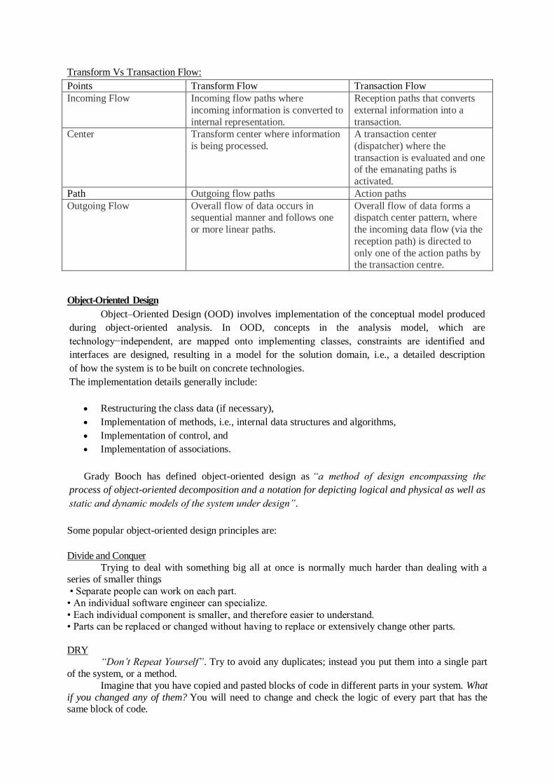
Class
A class is represented by a rectangle having three sections:
the top section containing the name of the class
the middle section containing class attributes
the bottom section representing operations of the class
The visibility of the attributes and operations can be represented in the following ways:
Public : A public member is visible from anywhere in the system. In class diagram, it is
prefixed by the symbol ‘+’.
Private : A private member is visible only from within the class. It cannot be accessed from
outside the class. A private member is prefixed by the symbol ‘−’.
Protected : A protected member is visible from within the class and from the subclasses
inherited from this class, but not from outside. It is prefixed by the symbol ‘#’.
An abstract class has the class name written in italics.
Example: Let us consider the Circle class introduced earlier. The attributes of Circle are x-coord, y-
coord, and radius. The operations are findArea(), findCircumference(), and scale(). Let us assume
that x-coord and y-coord are private data members, radius is a protected data member, and the
member functions are public. The following figure gives the diagrammatic representation of the
class.
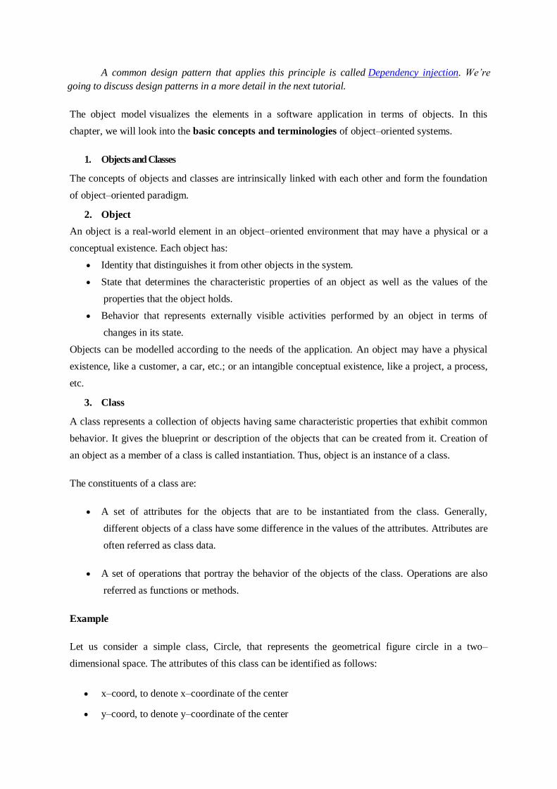
Object
An object is represented as a rectangle with two sections:
The top section contains the name of the object with the name of the class or package of
which it is an instance of. The name takes the following forms:
o object-name : class-name
o object-name : class-name :: package-name
o class-name : in case of anonymous objects
The bottom section represents the values of the attributes. It takes the form attribute-name =
value.
Sometimes objects are represented using rounded rectangles.
Example: Let us consider an object of the class Circle named c1. We assume that the center of c1 is
at (2, 3) and the radius of c1 is 5. The following figure depicts the object.
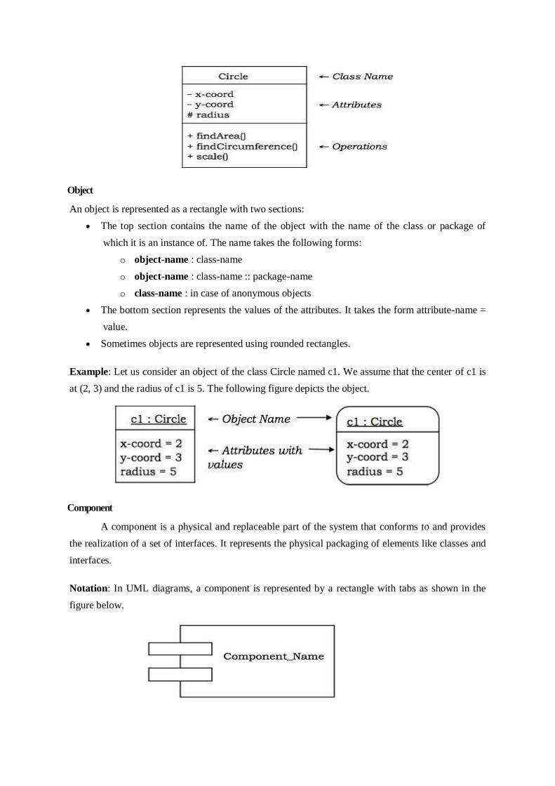
Component
A component is a physical and replaceable part of the system that conforms to and provides
the realization of a set of interfaces. It represents the physical packaging of elements like classes and
interfaces.
Notation: In UML diagrams, a component is represented by a rectangle with tabs as shown in the
figure below.

Interface
Interface is a collection of methods of a class or component. It specifies the set of services
that may be provided by the class or component.
Notation: Generally, an interface is drawn as a circle together with its name. An interface is almost
always attached to the class or component that realizes it. The following figure gives the notation of
an interface.
Package
A package is an organized group of elements. A package may contain structural things like
classes, components, and other packages in it.
Notation: Graphically, a package is represented by a tabbed folder. A package is generally drawn
with only its name. However it may have additional details about the contents of the package. See
the following figures.
Relationship
The notations for the different types of relationships are as follows:

Usually, elements in a relationship play specific roles in the relationship. A role name
signifies the behavior of an element participating in a certain context.
Example: The following figures show examples of different relationships between classes. The first
figure shows an association between two classes, Department and Employee, wherein a department
may have a number of employees working in it. Worker is the role name. The ‘1’ alongside
Department and ‘*’ alongside Employee depict that the cardinality ratio is one–to–many. The second
figure portrays the aggregation relationship, a University is the “whole–of” many Departments.
UML Structural Diagrams
UML structural diagrams are categorized as follows: class diagram, object diagram,
component diagram, and deployment diagram.
1. Class Diagram
A class diagram models the static view of a system. It comprises of the classes, interfaces,
and collaborations of a system; and the relationships between them.
Class Diagram of a System
Let us consider a simplified Banking System.
A bank has many branches. In each zone, one branch is designated as the zonal head office that
supervises the other branches in that zone. Each branch can have multiple accounts and loans. An
account may be either a savings account or a current account. A customer may open both a savings
account and a current account. However, a customer must not have more than one savings account or
current account. A customer may also procure loans from the bank.
The following figure shows the corresponding class diagram.
Classes in the system:
Bank, Branch, Account, Savings Account, Current Account, Loan, and Customer.
Relationships:
A Bank “has–a” number of Branches : composition, one–to–many

A Branch with role Zonal Head Office supervises other Branches : unary association,
one–to-many
A Branch “has–a” number of accounts : aggregation, one–to–many
From the class Account, two classes have inherited, namely, Savings Account and Current Account.
A Customer can have one Current Account : association, one–to–one
A Customer can have one Savings Account : association, one–to–one
A Branch “has–a” number of Loans : aggregation, one–to–many
A Customer can take many loans : association, one–to–many
2. Object Diagram
An object diagram models a group of objects and their links at a point of time. It shows the
instances of the things in a class diagram. Object diagram is the static part of an interaction diagram.
Example: The following figure shows an object diagram of a portion of the class diagram of the
Banking System.

3. Component Diagram
Component diagrams show the organization and dependencies among a group of components.
Component diagrams comprise of:
Components
Interfaces
Relationships
Packages and Subsystems (optional)
Component diagrams are used for:
Constructing systems through forward and reverse engineering.
Modelling configuration management of source code files while developing a system using
an object-oriented programming language.
Representing schemas in modeling databases.
Modeling behaviors of dynamic systems.
Example
The following figure shows a component diagram to model a system’s source code that is
developed using C++. It shows four source code files, namely, myheader.h, otherheader.h,
priority.cpp, and other.cpp. Two versions of myheader.h are shown, tracing from the recent version
to its ancestor. The file priority.cpp has compilation dependency on other.cpp. The file other.cpp has
compilation dependency on otherheader.h.

4. Deployment Diagram
A deployment diagram puts emphasis on the configuration of runtime processing nodes and their
components that live on them. They are commonly comprised of nodes and dependencies, or
associations between the nodes.
Deployment diagrams are used to:
Model devices in embedded systems that typically comprise of software-intensive collection
of hardware.
Represent the topologies of client/server systems.
Model fully distributed systems.
Example
The following figure shows the topology of a computer system that follows client/server
architecture. The figure illustrates a node stereotyped as server that comprises of processors. The
figure indicates that four or more servers are deployed at the system. Connected to the server are the
client nodes, where each node represents a terminal device such as workstation, laptop, scanner, or
printer. The nodes are represented using icons that clearly depict the real-world equivalent.

UML Behavioural Diagrams
UML behavioral diagrams visualize, specify, construct, and document the dynamic aspects of
a system. The behavioral diagrams are categorized as follows: use case diagrams, interaction
diagrams, state–chart diagrams, and activity diagrams.
5. Use Case Model
(a) Use case
A use case describes the sequence of actions a system performs yielding visible results. It
shows the interaction of things outside the system with the system itself. Use cases may be applied to
the whole system as well as a part of the system.
(b) Actor
An actor represents the roles that the users of the use cases play. An actor may be a person
(e.g. student, customer), a device (e.g. workstation), or another system (e.g. bank, institution).
The following figure shows the notations of an actor named Student and a use case called
Generate Performance Report.
(c) Use case diagrams
Use case diagrams present an outside view of the manner the elements in a system behave and how
they can be used in the context.
Use case diagrams comprise of:
Use cases
Actors
Relationships like dependency, generalization, and association
Use case diagrams are used:
To model the context of a system by enclosing all the activities of a system within a rectangle
and focusing on the actors outside the system by interacting with it.
To model the requirements of a system from the outside point of view.

Example
Let us consider an Automated Trading House System. We assume the following features of the
system:
The trading house has transactions with two types of customers, individual customers and
corporate customers.
Once the customer places an order, it is processed by the sales department and the customer
is given the bill.
The system allows the manager to manage customer accounts and answer any queries posted
by the customer.
Interaction Diagrams
Interaction diagrams depict interactions of objects and their relationships. They also include the
messages passed between them. There are two types of interaction diagrams:
Sequence Diagrams
Collaboration Diagrams
Interaction diagrams are used for modeling:
The control flow by time ordering using sequence diagrams.
The control flow of organization using collaboration diagrams.
6. Sequence Diagrams
Sequence diagrams are interaction diagrams that illustrate the ordering of messages
according to time.
Notations: These diagrams are in the form of two-dimensional charts. The objects that initiate the
interaction are placed on the x–axis. The messages that these objects send and receive are placed
along the y–axis, in the order of increasing time from top to bottom.
Example: A sequence diagram for the Automated Trading House System is shown in the following
figure.

7. Collaboration Diagrams
Collaboration diagrams are interaction diagrams that illustrate the structure of the objects that send
and receive messages.
Notations: In these diagrams, the objects that participate in the interaction are shown using vertices.
The links that connect the objects are used to send and receive messages. The message is shown as a
labelled arrow.
Example: Collaboration diagram for the Automated Trading House System is illustrated in the
figure below.
8. State–Chart Diagrams
A state–chart diagram shows a state machine that depicts the control flow of an object from
one state to another. A state machine portrays the sequences of states which an object undergoes due
to events and their responses to events.

State–Chart Diagrams comprise of:
States: Simple or Composite
Transitions between states
Events causing transitions
Actions due to the events
State-chart diagrams are used for modeling objects which are reactive in nature.
Example
In the Automated Trading House System, let us model Order as an object and trace its
sequence. The following figure shows the corresponding state–chart diagram.
9. Activity Diagrams
An activity diagram depicts the flow of activities which are ongoing non-atomic operations in
a state machine. Activities result in actions which are atomic operations.
Activity diagrams comprise of:
Activity states and action states
Transitions
Objects
Activity diagrams are used for modeling:
Workflows as viewed by actors, interacting with the system.
Details of operations or computations using flowcharts.

Example
The following figure shows an activity diagram of a portion of the Automated Trading House
System.