Finite Element Analysis of Riveted Joints in Old Steel Buildings in NZ
61
Riveted Joints
UNIT 3 RIVETED JOINTS
Structure
3.1 Introduction
Objectives
3.2 Head Forming
3.3 Types of Rivets
3.4 Types of Riveted Joints
3.5 Nomenclature
3.6 Modes of Failure of a Riveted Joint
3.7 Efficiency of Riveted Joints
3.8 Calculation of Hole Dia and Pitch
3.9 Riveted Joints in Structures
3.10 Joints for Boilers and Pressure Vessels
3.11 Design Procedure for Longitudinal Butt Joint
3.12 Design Procedure for Circumferential Lap Joint
3.13 Torsional Loading and Eccentric Loading of Riveted Joint
3.14 Summary
3.15 Key Words
3.16 Answers to SAQs
3.1 INTRODUCTION
In engineering practice it is often required that two sheets or plates are joined together
and carry the load in such ways that the joint is loaded. Many times such joints are
required to be leak proof so that gas contained inside is not allowed to escape. A riveted
joint is easily conceived between two plates overlapping at edges, making holes through
thickness of both, passing the stem of rivet through holes and creating the head at the end
of the stem on the other side. A number of rivets may pass through the row of holes,
which are uniformly distributed along the edges of the plate. With such a joint having
been created between two plates, they cannot be pulled apart. If force at each of the free
edges is applied for pulling the plate apart the tensile stress in the plate along the row of
rivet hole and shearing stress in rivets will create resisting force. Such joints have been
used in structures, boilers and ships.
The development of welding technology in 1940s has considerably reduced the riveted
joint applications. Welding is the method of locally melting the metals (sheets or plates –
overlapping or butting) with intensive heating along with a filler metal or without it and
allowing to cool them to form a coherent mass, thus creating a joint. Such joints can be
created to make structures, boilers, pressure vessels, etc. and are more conveniently
made in steel. The progress has been made in welding several types of steels but large
structure size may impede the use of automatic techniques and heat treatment which
becomes necessary in some cases. Welded ships were made in large size and large
number during Second World War and failures of many of them spurted research efforts
to make welding a better technology.
Objectives
After studying this unit, you should be able to
describe the types of riveted joint,
calculate the strength of riveted joints,
62
Machine Design
explain how many different ways the riveted joints can fail,
design riveted joints for boilers, structure and under eccentric loads.
3.2 HEAD FORMING
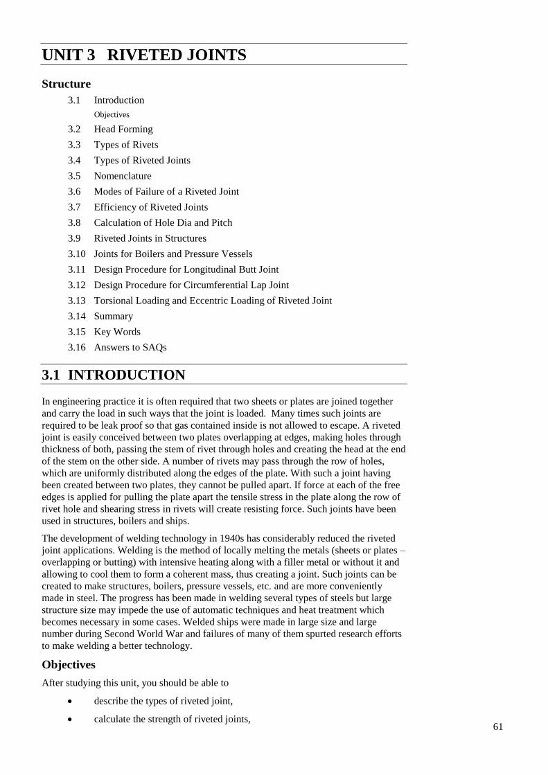
You know that the riveted joint is created by passing the stem of a rivet through holes in
two plates as is shown in Figure 3.1(a). The creation of head by process of upsetting is
shown in Figure 3.1(b). The upsetting of the cylindrical portion of the rivet can be done
cold or hot. When diameter of rivet is 12 mm or less, cold upsetting can be done. For
larger diameters the rivet is first heated to light red and inserted. The head forming
immediately follows. The rivet completely fills the hole in hot process. Yet it must be
understood that due to subsequent cooling the length reduces and diameter decreases.
The reduction of length pulls the heads of rivet against plates and makes the joint
slightly stronger. The reduction of diameter creates clearance between the inside of the
hole and the rivet. Such decrease in length and diameter does not occur in cold worked
rivet.
a
d1
tt
(a) (b)
Figure 3.1 : Typical Head Forming of Rivet
3.3 TYPES OF RIVETS
For steel plates the rivets are normally made in low carbon steel. However, the rivets in
copper add to resistance against corrosion and aluminum rivets can be used to reduce the
overall weight of the structure. The low carbon steel is standardized in composition
particularly for boiler applications.
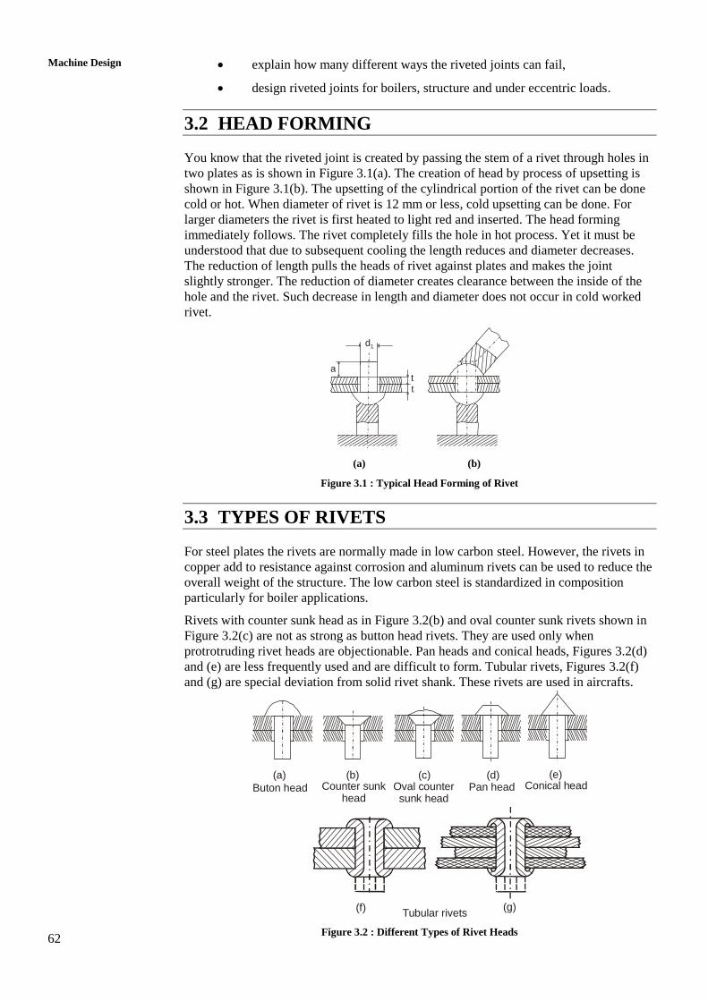
Rivets with counter sunk head as in Figure 3.2(b) and oval counter sunk rivets shown in
Figure 3.2(c) are not as strong as button head rivets. They are used only when
protrotruding rivet heads are objectionable. Pan heads and conical heads, Figures 3.2(d)
and (e) are less frequently used and are difficult to form. Tubular rivets, Figures 3.2(f)
and (g) are special deviation from solid rivet shank. These rivets are used in aircrafts.
(b)
Buton head
(a)Counter sunk
head
(c)Oval counter sunk head
(d)Pan head
(e)Conical head
(f)Tubular rivets
(g)
Figure 3.2 : Different Types of Rivet Heads
63
Riveted Joints 3.4 TYPES OF RIVETED JOINTS
The classification of riveted joints is based on following :
(a) According to purpose,
(b) According to position of plates connected, and
(c) According to arrangement of rivets.
According to purpose the riveted joints are classified as :
Strong Joints
In these joints strength is the only criterion. Joints in engineering structure such as
beams, trusses and machine frames are strong joints.
Tight Joints
These joints provide strength as well as are leak proof against low pressures.
Joints in reservoirs, containers and tanks fall under this group.
Strong Tight Joints
These are joints applied in boilers and pressure vessels and ensure both strength
and leak proofness.
This classification has no sound basis and is arbitrary. However, it helps understand the
basis of design and manufacturing. The hot working of rivets is one-way of making
intimate contact between plates in the areas of joint. Further, the holes are drilled and
reamed to required tolerances and burrs removed for good contact before rivets are
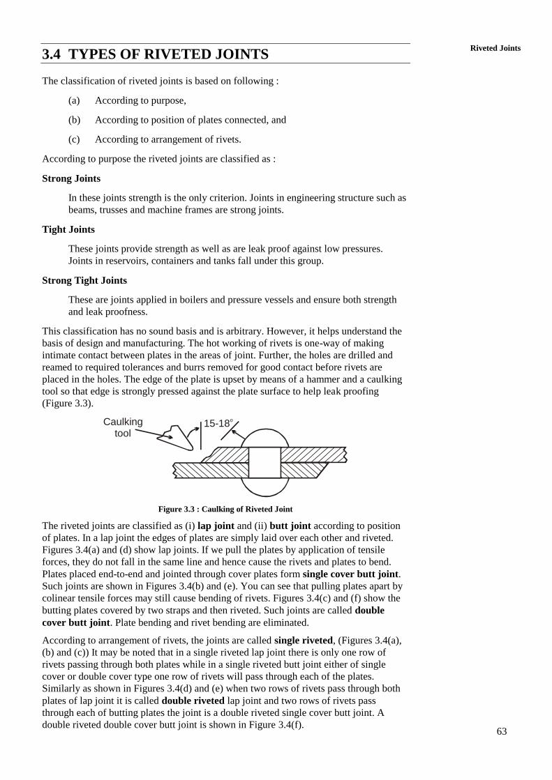
placed in the holes. The edge of the plate is upset by means of a hammer and a caulking
tool so that edge is strongly pressed against the plate surface to help leak proofing
(Figure 3.3).
Caulking tool
15-18o
Figure 3.3 : Caulking of Riveted Joint
The riveted joints are classified as (i) lap joint and (ii) butt joint according to position
of plates. In a lap joint the edges of plates are simply laid over each other and riveted.
Figures 3.4(a) and (d) show lap joints. If we pull the plates by application of tensile
forces, they do not fall in the same line and hence cause the rivets and plates to bend.
Plates placed end-to-end and jointed through cover plates form single cover butt joint.
Such joints are shown in Figures 3.4(b) and (e). You can see that pulling plates apart by
colinear tensile forces may still cause bending of rivets. Figures 3.4(c) and (f) show the
butting plates covered by two straps and then riveted. Such joints are called double
cover butt joint. Plate bending and rivet bending are eliminated.
According to arrangement of rivets, the joints are called single riveted, (Figures 3.4(a),
(b) and (c)) It may be noted that in a single riveted lap joint there is only one row of
rivets passing through both plates while in a single riveted butt joint either of single
cover or double cover type one row of rivets will pass through each of the plates.
Similarly as shown in Figures 3.4(d) and (e) when two rows of rivets pass through both
plates of lap joint it is called double riveted lap joint and two rows of rivets pass
through each of butting plates the joint is a double riveted single cover butt joint. A
double riveted double cover butt joint is shown in Figure 3.4(f).
64
Machine Design
tt t
d
d
d d
t/2
(a) (b) (c)
t/2
P
m
m
m
P
m
m
d
tt
t
P
m Pb m
Pb
Pb
PP
2
t
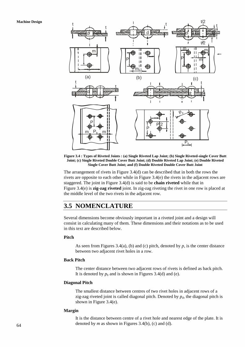
Figure 3.4 : Types of Riveted Joints : (a) Single Riveted Lap Joint; (b) Single Riveted-single Cover Butt
Joint; (c) Single Riveted Double Cover Butt Joint; (d) Double Riveted Lap Joint; (e) Double Riveted
Single Cover Butt Joint; and (f) Double Riveted Double Cover Butt Joint
The arrangement of rivets in Figure 3.4(d) can be described that in both the rows the
rivets are opposite to each other while in Figure 3.4(e) the rivets in the adjacent rows are
staggered. The joint in Figure 3.4(d) is said to be chain riveted while that in
Figure 3.4(e) is zig-zag riveted joint. In zig-zag riveting the rivet in one row is placed at
the middle level of the two rivets in the adjacent row.
3.5 NOMENCLATURE
Several dimensions become obviously important in a riveted joint and a design will
consist in calculating many of them. These dimensions and their notations as to be used
in this text are described below.
Pitch
As seen from Figures 3.4(a), (b) and (c) pitch, denoted by p, is the center distance
between two adjacent rivet holes in a row.
Back Pitch
The center distance between two adjacent rows of rivets is defined as back pitch.
It is denoted by pb and is shown in Figures 3.4(d) and (e).
Diagonal Pitch
The smallest distance between centres of two rivet holes in adjacent rows of a
zig-zag riveted joint is called diagonal pitch. Denoted by pd, the diagonal pitch is
shown in Figure 3.4(e).
Margin
It is the distance between centre of a rivet hole and nearest edge of the plate. It is
denoted by m as shown in Figures 3.4(b), (c) and (d).
65
Riveted Joints The plates to be jointed are often of the same thickness and their thickness is denoted
by t. However, if the thicknesses are different, the lower one will be denoted by t1. The
thickness of the cover plate (also known as strap) in a butt joint will be denoted as tc.
The rivet hole diameter is denoted by d. This diameter is normally large than the
diameter of the rivet shank which is denoted by d1.
A problem of designing of a riveted joint involves determinations of p, pb, pd, m, t, tc and
d, depending upon type of the joint.
3.6 MODES OF FAILURE OF A RIVETED JOINT
A riveted joint may fail in several ways but the failure occurs as soon as failure takes
place in any one mode. Following is the description of modes of failures of a riveted
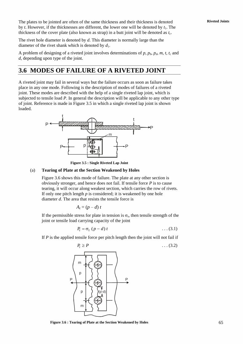
joint. These modes are described with the help of a single riveted lap joint, which is
subjected to tensile load P. In general the description will be applicable to any other type
of joint. Reference is made in Figure 3.5 in which a single riveted lap joint is shown
loaded.
tt
p
P
m
P
pP
m
P
Figure 3.5 : Single Riveted Lap Joint
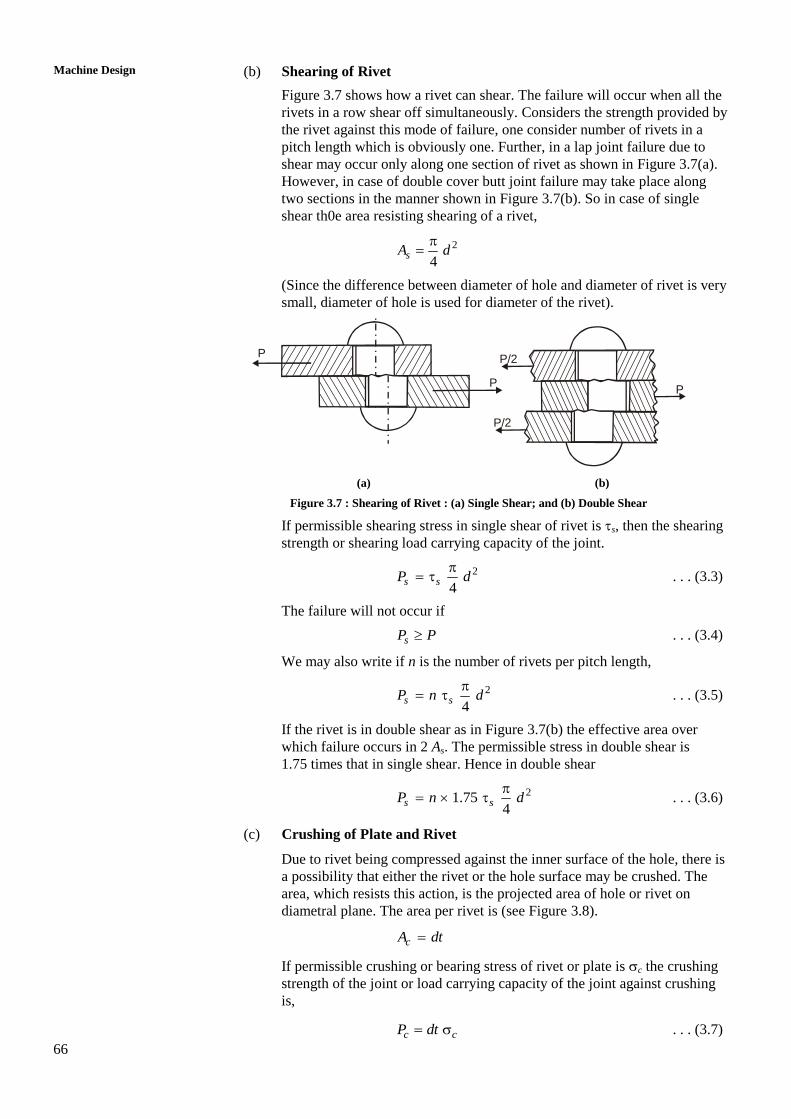
(a) Tearing of Plate at the Section Weakened by Holes
Figure 3.6 shows this mode of failure. The plate at any other section is
obviously stronger, and hence does not fail. If tensile force P is to cause
tearing, it will occur along weakest section, which carries the row of rivets.
If only one pitch length p is considered; it is weakened by one hole
diameter d. The area that resists the tensile force is
At = (p – d) t
If the permissible stress for plate in tension is t, then tensile strength of the
joint or tensile load carrying capacity of the joint
( ) t tP p d t . . . (3.1)
If P is the applied tensile force per pitch length then the joint will not fail if
tP P . . . (3.2)
m
m
P P
(p-d)
p
p
Figure 3.6 : Tearing of Plate at the Section Weakened by Holes
66
Machine Design
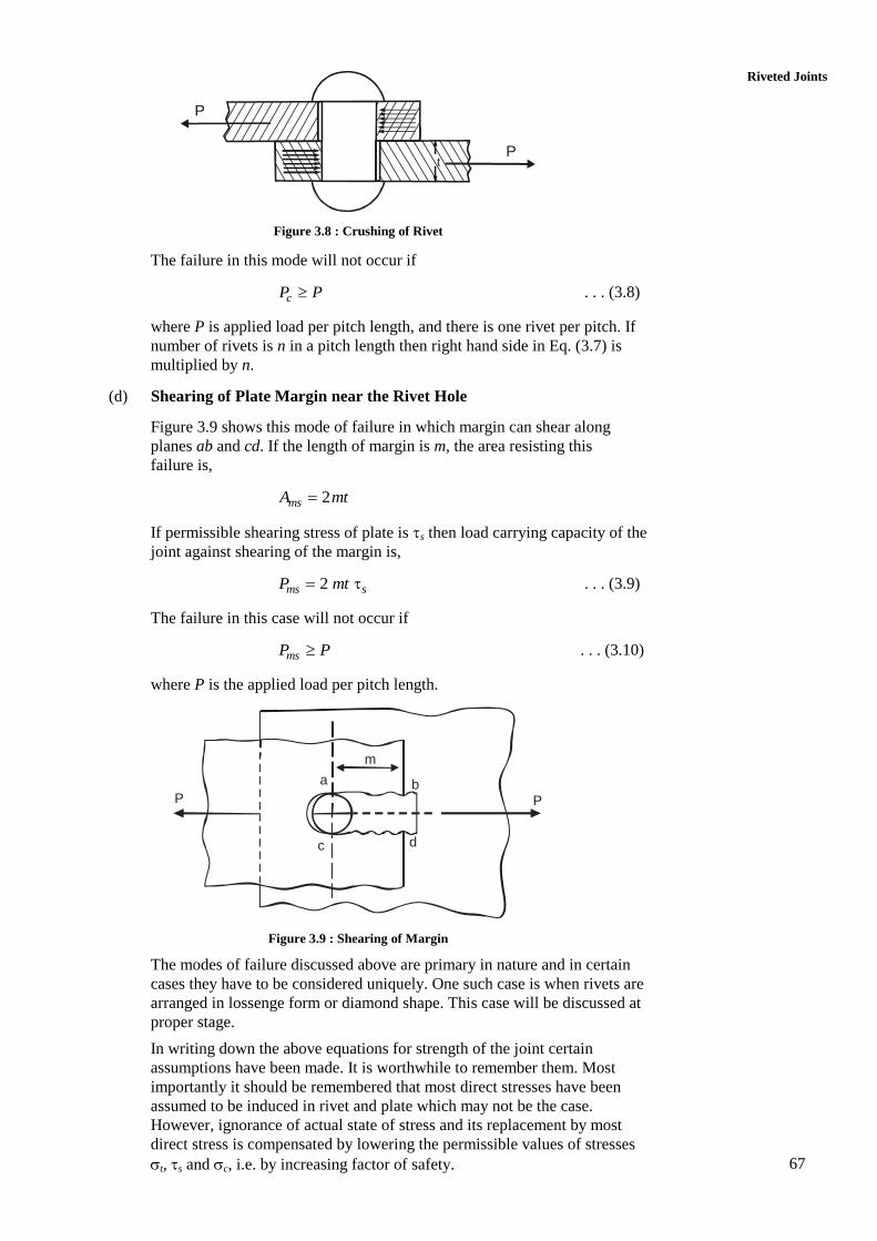
(b) Shearing of Rivet
Figure 3.7 shows how a rivet can shear. The failure will occur when all the
rivets in a row shear off simultaneously. Considers the strength provided by
the rivet against this mode of failure, one consider number of rivets in a
pitch length which is obviously one. Further, in a lap joint failure due to
shear may occur only along one section of rivet as shown in Figure 3.7(a).
However, in case of double cover butt joint failure may take place along
two sections in the manner shown in Figure 3.7(b). So in case of single
shear th0e area resisting shearing of a rivet,
2
4sA d
(Since the difference between diameter of hole and diameter of rivet is very
small, diameter of hole is used for diameter of the rivet).
P
P
P/2
P/2
P
(a) (b)
Figure 3.7 : Shearing of Rivet : (a) Single Shear; and (b) Double Shear
If permissible shearing stress in single shear of rivet is s, then the shearing
strength or shearing load carrying capacity of the joint.
2
4s sP d
. . . (3.3)
The failure will not occur if
sP P . . . (3.4)
We may also write if n is the number of rivets per pitch length,
2
4s sP n d
. . . (3.5)
If the rivet is in double shear as in Figure 3.7(b) the effective area over
which failure occurs in 2 As. The permissible stress in double shear is
1.75 times that in single shear. Hence in double shear
21.754
s sP n d
. . . (3.6)
(c) Crushing of Plate and Rivet
Due to rivet being compressed against the inner surface of the hole, there is
a possibility that either the rivet or the hole surface may be crushed. The
area, which resists this action, is the projected area of hole or rivet on
diametral plane. The area per rivet is (see Figure 3.8).
cA dt
If permissible crushing or bearing stress of rivet or plate is c the crushing
strength of the joint or load carrying capacity of the joint against crushing
is,
c cP dt . . . (3.7)
67
Riveted Joints
P
Pt
Figure 3.8 : Crushing of Rivet
The failure in this mode will not occur if
cP P . . . (3.8)
where P is applied load per pitch length, and there is one rivet per pitch. If
number of rivets is n in a pitch length then right hand side in Eq. (3.7) is
multiplied by n.
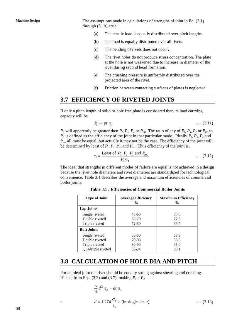
(d) Shearing of Plate Margin near the Rivet Hole
Figure 3.9 shows this mode of failure in which margin can shear along
planes ab and cd. If the length of margin is m, the area resisting this
failure is,
2msA mt
If permissible shearing stress of plate is s then load carrying capacity of the
joint against shearing of the margin is,
2 ms sP mt . . . (3.9)
The failure in this case will not occur if
msP P . . . (3.10)
where P is the applied load per pitch length.
P P
m
a
c d
b
Figure 3.9 : Shearing of Margin
The modes of failure discussed above are primary in nature and in certain
cases they have to be considered uniquely. One such case is when rivets are
arranged in lossenge form or diamond shape. This case will be discussed at
proper stage.
In writing down the above equations for strength of the joint certain
assumptions have been made. It is worthwhile to remember them. Most
importantly it should be remembered that most direct stresses have been
assumed to be induced in rivet and plate which may not be the case.
However, ignorance of actual state of stress and its replacement by most
direct stress is compensated by lowering the permissible values of stresses
t, s and c, i.e. by increasing factor of safety.
68
Machine Design
The assumptions made in calculations of strengths of joint in Eq. (3.1)
through (3.10) are :
(a) The tensile load is equally distributed over pitch lengths.
(b) The load is equally distributed over all rivets.
(c) The bending of rivets does not occur.
(d) The rivet holes do not produce stress concentration. The plate
at the hole is not weakened due to increase in diameter of the
rivet during second head formation.
(e) The crushing pressure is uniformly distributed over the
projected area of the rivet.
(f) Friction between contacting surfaces of plates is neglected.
3.7 EFFICIENCY OF RIVETED JOINTS
If only a pitch length of solid or hole free plate is considered then its load carrying
capacity will be
1 tP pt . . . (3.11)
P1 will apparently be greater then Pt, Ps, Pc or Pms. The ratio of any of Pt, Ps, Pc or Pms to
P1 is defined as the efficiency of the joint in that particular mode. Ideally Pt, Ps, Pc and
Pms all must be equal, but actually it may not be the case. The efficiency of the joint will
be determined by least of Pt, Ps, Pc, and Pms. Thus efficiency of the joint is,
Least of , , and
t s c ms
t t
P P P P
P . . . (3.12)
The ideal that strengths in different modes of failure are equal is not achieved in a design
because the rivet hole diameters and rivet diameters are standardized for technological
convenience. Table 3.1 describes the average and maximum efficiencies of commercial
boiler joints.
Table 3.1 : Efficiencies of Commercial Boiler Joints
Type of Joint Average Efficiency
%
Maximum Efficiency
%
Lap Joints
Single riveted
Double riveted
Triple riveted
45-60
63-70
72-80
63.3
77.5
86.5
Butt Joints
Single riveted
Double riveted
Triple riveted
Quadruple riveted
55-60
70-83
80-90
85-94
63.3
86.6
95.0
98.1
3.8 CALCULATION OF HOLE DIA AND PITCH
For an ideal joint the rivet should be equally strong against shearing and crushing.
Hence, from Eqs. (3.3) and (3.7), making Ps = Pc
2
4s cd dt
1.274 c
s
d t
(in single shear) . . . (3.13)
69
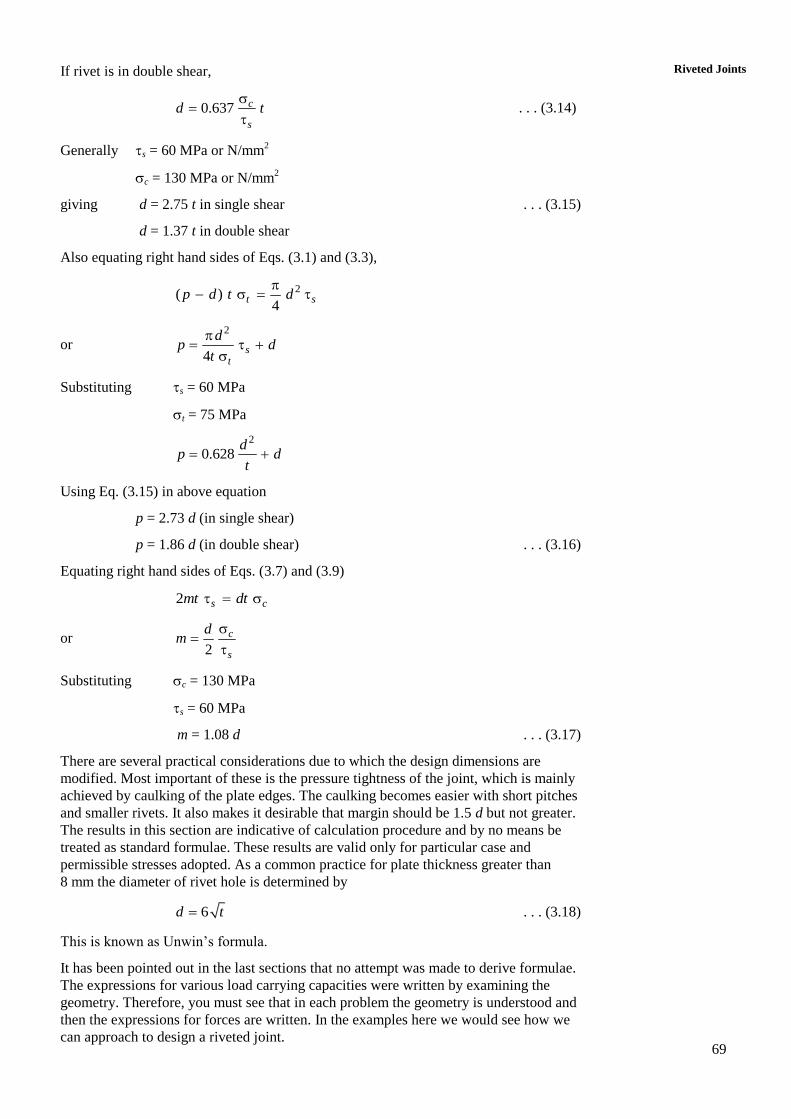
Riveted Joints If rivet is in double shear,
0.637 c
s
d t
. . . (3.14)
Generally s = 60 MPa or N/mm2
c = 130 MPa or N/mm2
giving d = 2.75 t in single shear . . . (3.15)
d = 1.37 t in double shear
Also equating right hand sides of Eqs. (3.1) and (3.3),
2( )4
t sp d t d
or 2
4s
t
dp d
t
Substituting s = 60 MPa
t = 75 MPa
2
0.628d
p dt
Using Eq. (3.15) in above equation
p = 2.73 d (in single shear)
p = 1.86 d (in double shear) . . . (3.16)
Equating right hand sides of Eqs. (3.7) and (3.9)
2 s cmt dt
or 2
c
s
dm
Substituting c = 130 MPa
s = 60 MPa
m = 1.08 d . . . (3.17)
There are several practical considerations due to which the design dimensions are
modified. Most important of these is the pressure tightness of the joint, which is mainly
achieved by caulking of the plate edges. The caulking becomes easier with short pitches
and smaller rivets. It also makes it desirable that margin should be 1.5 d but not greater.
The results in this section are indicative of calculation procedure and by no means be
treated as standard formulae. These results are valid only for particular case and
permissible stresses adopted. As a common practice for plate thickness greater than
8 mm the diameter of rivet hole is determined by
6d t . . . (3.18)
This is known as Unwin’s formula.
It has been pointed out in the last sections that no attempt was made to derive formulae.
The expressions for various load carrying capacities were written by examining the
geometry. Therefore, you must see that in each problem the geometry is understood and
then the expressions for forces are written. In the examples here we would see how we
can approach to design a riveted joint.
70
Machine Design
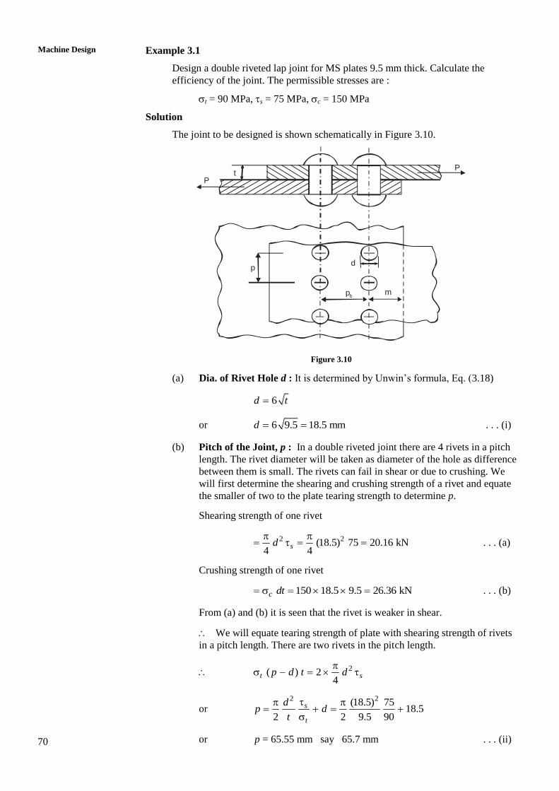
Example 3.1
Design a double riveted lap joint for MS plates 9.5 mm thick. Calculate the
efficiency of the joint. The permissible stresses are :
t = 90 MPa, s = 75 MPa, c = 150 MPa
Solution
The joint to be designed is shown schematically in Figure 3.10.
P
Pt
d
m
p
pb
Figure 3.10
(a) Dia. of Rivet Hole d : It is determined by Unwin’s formula, Eq. (3.18)
6d t
or 6 9.5 18.5 mmd . . . (i)
(b) Pitch of the Joint, p : In a double riveted joint there are 4 rivets in a pitch
length. The rivet diameter will be taken as diameter of the hole as difference
between them is small. The rivets can fail in shear or due to crushing. We
will first determine the shearing and crushing strength of a rivet and equate
the smaller of two to the plate tearing strength to determine p.
Shearing strength of one rivet
2 2(18.5) 75 20.16 kN4 4
sd
. . . (a)
Crushing strength of one rivet
150 18.5 9.5 26.36 kNc dt . . . (b)
From (a) and (b) it is seen that the rivet is weaker in shear.
We will equate tearing strength of plate with shearing strength of rivets
in a pitch length. There are two rivets in the pitch length.
2( ) 24
t sp d t d
or 2 2(18.5) 75
18.52 2 9.5 90
s
t
dp d
t
or p = 65.55 mm say 65.7 mm . . . (ii)
71
Riveted Joints The pitch should be such that head forming operation is not hindered. The
practice dictates that p 3 d so that head forming is permitted.
3 d = 55.5 mm, and hence the value of p obtained in (ii) is acceptable.
(c) The back Pitch pb : It must be between 2.5 d to 3.0 d. For chain riveting the
higher value is preferred for the reason of head forming
3 3 18.5 55.5 mm bp d . . . (iii)
(d) Margin, m : m is determined by equating shearing strength of rivet (smaller
of shearing and crushing strengths of rivet). Remember that there are two
rivets per pitch length :
22 24
s smt d
22 (18.5)
28.3 mm4 4 9.5
dm
t
. . . (iv)
The minimum acceptable value of m is 1.5 d = 27.5 mm hence
m = 28.3 mm is acceptable.
Thus the design is completed with
d = 18.5 mm, p = 65.7 mm, pb = 55.5 mm, m = 28.3 mm
The diameter is standardized, apparently based on drill size. Normally
fractions like 18.5 mm may not be accepted. The rivet diameters are less
than hole diameter by 1 mm. Yet the head formation process increases rivet
diameter. We are not yet describing standard hole and rivet diameters.
We postpone it for the time being.
(e) Efficiency of Joint
Tensile strength of plate without holes, per pitch length
1 90 65.7 9.5 56.2 kNtP pt . . . (c)
Shearing strength of rivets in a pitch length
2 22 2 75 (18.5) 40.3 kN4 4
s sP d
. . . (d)
Crushing strength of rivets in a pitch length
2 2 150 18.5 9.5 52.7 kNc cP d t . . . (e)
The tearing strength of plate with one hole in a pitch length
( ) 90 (65.7 18.5) 9.5 40.36 kNt tP p d t . . . (f)
The shearing strength of margin
2 2 75 28.3 9.5 40.32 kNms sP mt . . . (g)
Out of all Ps, Pc, Pt and Pms, the lowest is Pm
1
40.371.7%
56.2
sP
P . . . (h)
The design values are
d = 18.5 mm, p = 65.7 mm, pb = 55.5 mm, m = 28.3 mm, = 71.7%
72
Machine Design
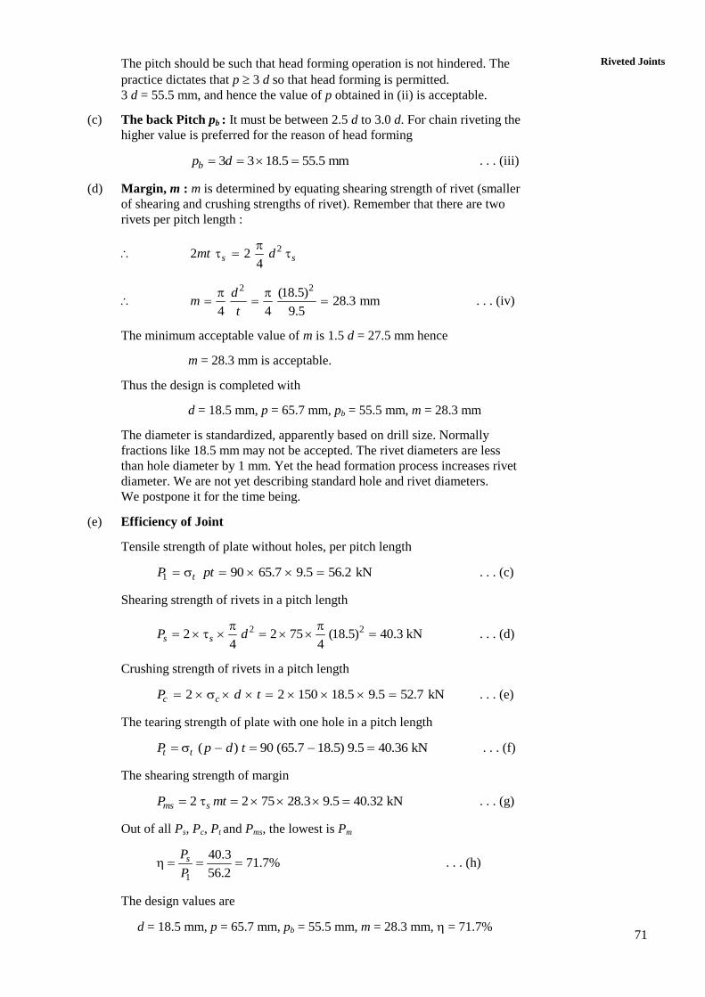
3.9 RIVETED JOINTS IN STRUCTURES
For trusses, bridges or girders, etc. where the width of the plates is known in advance
lozenge type or diamond shaped joints are preferred. These joints have uniform or equal
strengths in all modes of failure. Marginal adjustments in calculated dimensions may
slightly reduce or increase strength in any particular mode. The joints are usually of
double cover butt type with rivets so arranged that there is only one rivet in the
outermost row and their number increases towards inner row. (See Figure 3.11). Since
the plate width is known in advance, its strength in tension can be determined. Thus the
load carrying capacity of the joint
( )tP b d t
500kN
21 3 4
53.7
5
32.2
5 m
m
53
.75
53.7
5
53.7
5
53.7
5
53.7
5
53
.75
32.2
5 m
m
85.9 mm
400kN322.25 mm
21.5Ø
Figure 3.11
Here b is the plate width, t is thickness and d, the diameter of the hole. t is the
permissible tensile stress. The rivet diameter is determined by Unwin’s relationship. The
determination of number of rivets is the main task for the required force that is carried by
the member. Of course we would first determine whether the strength of rivet is less in
shear or in crushing which would depend upon relative magnitudes of s and c as well
as on the cross sectional area of the rivet and its projected area. The next step would be
to arrange the rivets in diamond shape as shown in Figure 3.11. Then we decide upon the
pitch, back pitch and margin.
The joint is designed not to tear in the outer most row, i.e. row 1 in Figure 3.11. Then the
row 2, which is the next inner row and weakened by two rivet holes, is subjected to
tearing. Note that this tearing is possible if rivet in the outermost row (or row 1) shears
or is crushed at the same time. That means this type of joint has one more possible mode
of failure which comprises tearing along an inner row accompanied by shearing or
crushing of rivets in all outer rows. The strength in this mode is denoted by Pts or Ptc and
one more suffix may be used to denote the row in which tearing will occur.
Thus 22 ( 2 )
4ts t sP b d t d
or 2 ( 2 )tc t cP b d t dt
And 23 ( 3 ) 3
4ts t sP b d t d
or 3 ( 3 ) 3tc t cP b d t dt
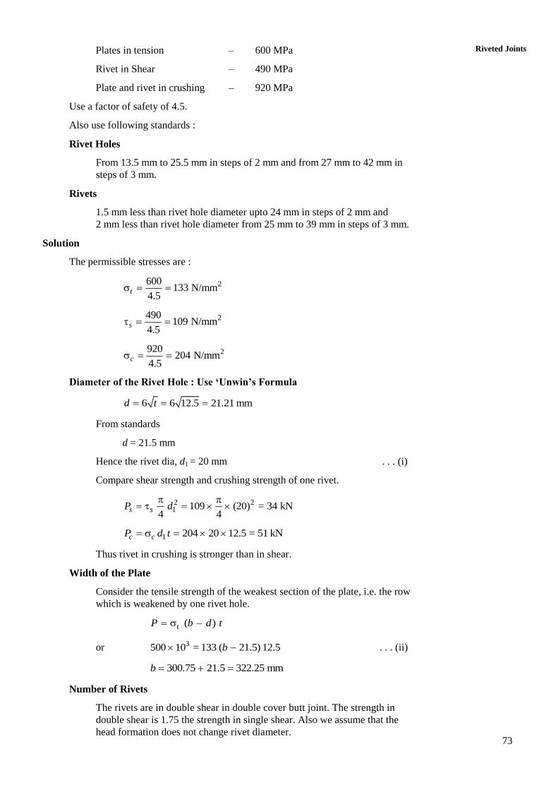
Example 3.2
Two steel plates 12.5 mm thick are required to carry a tensile load of 500 kN in a
double cover butt joint. Calculate the width of the plate if it is not to be weakened
by more than one rivet hole. Design the butt joint completely and show
dimensions on a sketch. The ultimate values of strengths are as follow :
73
Riveted Joints Plates in tension – 600 MPa
Rivet in Shear – 490 MPa
Plate and rivet in crushing – 920 MPa
Use a factor of safety of 4.5.
Also use following standards :
Rivet Holes
From 13.5 mm to 25.5 mm in steps of 2 mm and from 27 mm to 42 mm in
steps of 3 mm.
Rivets
1.5 mm less than rivet hole diameter upto 24 mm in steps of 2 mm and
2 mm less than rivet hole diameter from 25 mm to 39 mm in steps of 3 mm.
Solution
The permissible stresses are :
2600133 N/mm
4.5 t
2490109 N/mm
4.5s
2920204 N/mm
4.5c
Diameter of the Rivet Hole : Use ‘Unwin’s Formula
6 6 12.5 21.21 mmd t
From standards
d = 21.5 mm
Hence the rivet dia, d1 = 20 mm . . . (i)
Compare shear strength and crushing strength of one rivet.
2 21 109 (20) = 34 kN
4 4
s sP d
1 204 20 12.5 = 51 kNc cP d t
Thus rivet in crushing is stronger than in shear.
Width of the Plate
Consider the tensile strength of the weakest section of the plate, i.e. the row
which is weakened by one rivet hole.
( )tP b d t
or 3500 10 = 133 ( 21.5) 12.5b . . . (ii)
300.75 21.5 322.25 mmb
Number of Rivets
The rivets are in double shear in double cover butt joint. The strength in
double shear is 1.75 the strength in single shear. Also we assume that the
head formation does not change rivet diameter.
74
Machine Design
211.75 1.75 34 = 59.5 kN
4s sP d
i.e. 59.5 500 kNsn P P n
Also crushing strength
i.e. 51 500 cn P P n
or 500
9.8 say 1051
n . . . (iii)
We will see that 10 rivets are better arranged.
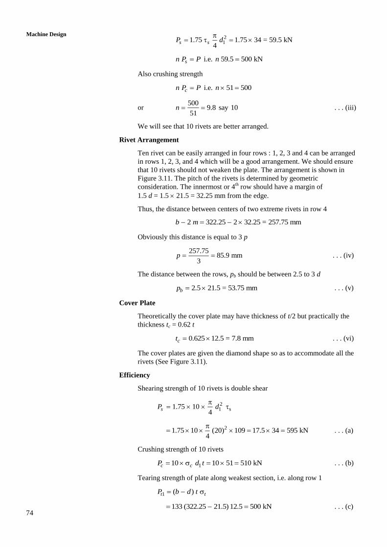
Rivet Arrangement
Ten rivet can be easily arranged in four rows : 1, 2, 3 and 4 can be arranged
in rows 1, 2, 3, and 4 which will be a good arrangement. We should ensure
that 10 rivets should not weaken the plate. The arrangement is shown in
Figure 3.11. The pitch of the rivets is determined by geometric
consideration. The innermost or 4th row should have a margin of
1.5 d = 1.5 21.5 = 32.25 mm from the edge.
Thus, the distance between centers of two extreme rivets in row 4
2 322.25 2 32.25 = 257.75 mmb m
Obviously this distance is equal to 3 p
257.75
85.9 mm3
p . . . (iv)
The distance between the rows, pb should be between 2.5 to 3 d
2.5 21.5 = 53.75 mmbp . . . (v)
Cover Plate
Theoretically the cover plate may have thickness of t/2 but practically the
thickness tc = 0.62 t
0.625 12.5 = 7.8 mm ct . . . (vi)
The cover plates are given the diamond shape so as to accommodate all the
rivets (See Figure 3.11).
Efficiency
Shearing strength of 10 rivets is double shear
21 s1.75 10
4sP d
21.75 10 (20) 109 17.5 34 595 kN4
. . . (a)
Crushing strength of 10 rivets
110 10 51 510 kNc cP d t . . . (b)
Tearing strength of plate along weakest section, i.e. along row 1
1 ( )t tP b d t
133 (322.25 21.5) 12.5 500 kN . . . (c)
75
Riveted Joints Strength for tearing along second row and crushing of one rivet in row 1
2 1133 (322.25 2 21.5) 12.5tc cP d t
133 279.25 12.5 204 20 12.5
464.25 51 kN
or 2 515.5 kNtcP . . . (d)
Strength for tearing along third row and crushing of 3 rivets in row 1 and 2
3 1133 (322.25 3 21.5) 12.5 3tc cP d t
3133 257.75 12.5 3 51 10 428.5 3 51 kN . . . (e)
or 3 581.5 kNtcP
Strength for tearing along fourth row and crushing of rivets in other rows
34 133 (322.25 4 21.5) 12.5 6 51 10tcP
or 4 699 kNtcP . . . (f)
(e) and (f) were expected to be more than (d), yet the calculations have been
made for the sake of completeness.
Strength of solid plate without hole
133 322.25 12.5 535.74 kNt tP bt . . . (g)
The least of all strengths from (a) through (f) is Pt1 = 500 kN
1 500100 100
535.74
t
t
P
P
93.3% . . . (vii)
SAQ 1
(a) Describe types of riveted joints.
(b) What are different modes of failure of riveted joints?
(c) Define pitch, back pitch, margin and diagonal pitch.
(d) Define efficiency of a riveted joint and write expression for various
strengths.
(e) A structural joint of double cover butt type has an efficiency of 85% with
the condition that the lowest strength is in tearing mode of 10.5 mm thick
plate in outer most row which is weakened by one hole. Find the tensile
force carried by the joint and the number of rivets if permissible stresses for
plate and rivet are; t = 105 N/mm2, s = 75 N/mm
2 and c = 150 N/mm
2.
Design the joint completely and show d, d1, p, pb and m on the sketch. Also
give dimension of cover plate.
76
Machine Design
3.10 JOINTS FOR BOILERS AND PRESSURE
VESSELS
The boiler and pressure vessels are cylindrical in shape and withstand internal pressure.
The vessels are required to be leak proof. The maintenance of pressure and safety of
boilers have prompted several standards. ASME boiler code, Board of Trade (BOT)
Rules, Indian Boiler Regulations (IBR) and ISI standards are available for design of
boilers and pressure vessels.
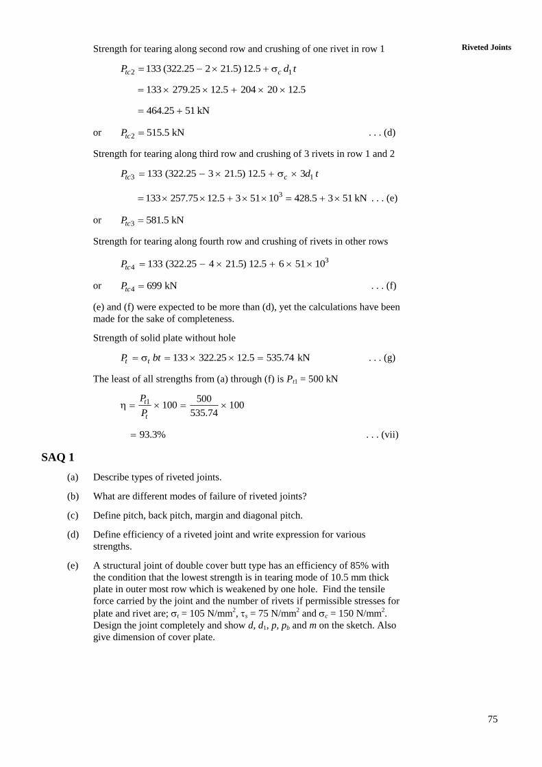
The cylindrical pressure vessel is identified by two dimensions, viz., the length and
diameter. The cylinders are made from plates and whole length may not be obtained
from single sheet hence cylindrical sections are obtained by bending sheets and joining
edges by riveted joint. The sections are then joined together by another riveted joint
along circumference. Thus there are two types of joint longitudinal and circumferential
(see Figure 3.12). The longitudinal joint will bear hoop stress (h) and circumferential
joint bears longitudinal stress (l). Since h = 2l, the longitudinal joint will have to be
two times as strong as circumferential joint. Therefore, longitudinal joints are always
made butt joints whereas the circumferential joints are mode as lap joints.
LocationLongitudinalJoint
LocationCircumferential Joint
Length section
Figure 3.12 : Longitudinal and Circumferential Location for Riveted Joints
The steps followed in design of boiler riveted joints are same as followed in any joint
design. They are mentioned here as described in IBR.
3.11 DESIGN PROCEDURE FOR LONGITUDINAL
BUTT JOINT
Determine Thickness of Boiler Shell (t)
The efficiency of the joint is chosen from Table 3.1 and for pressure r, inner
diameter D and permissible tensile stress t, the thickness is calculated from,
1 mm2
r
t
Dt
. . . (3.19)
The diameter and thickness will further guide in respect of rivet arrangement.
Table 3.2 can be used for this purpose.
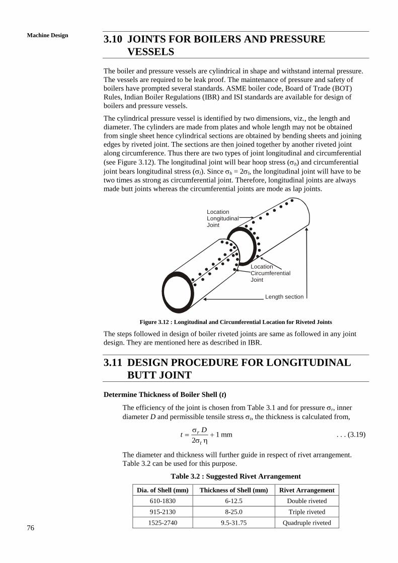
Table 3.2 : Suggested Rivet Arrangement
Dia. of Shell (mm) Thickness of Shell (mm) Rivet Arrangement
610-1830 6-12.5 Double riveted
915-2130 8-25.0 Triple riveted
1525-2740 9.5-31.75 Quadruple riveted
77
Riveted Joints Determine Rivet Hole Diameter (d) and Rivet Diameter (d1)
Unwin’s formula, giving 6d t is used if t 8 mm. In very rare case if
t < 8 mm, d is calculated by equating shearing strength and crushing strength of
rivet. The diameter of hole must be rounded off to the nearest standard value with
the help of Table 3.3, and the diameter of rivet also established.
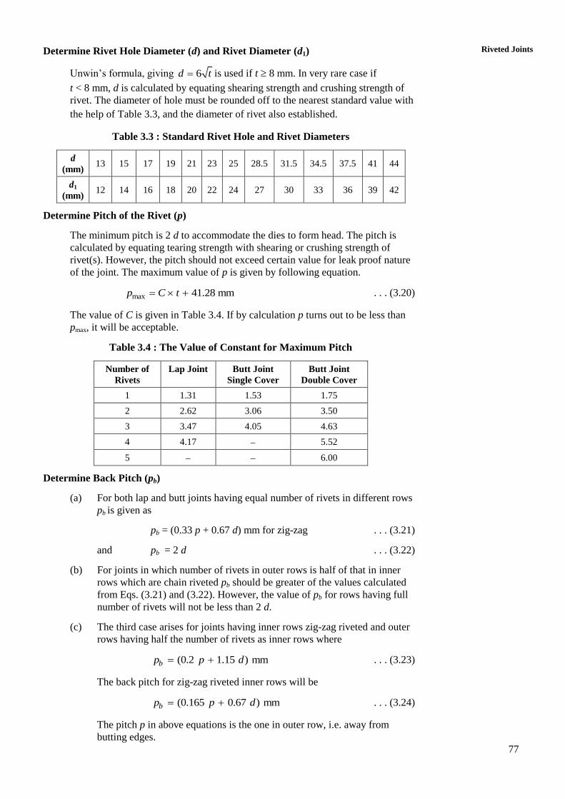
Table 3.3 : Standard Rivet Hole and Rivet Diameters
d
(mm) 13 15 17 19 21 23 25 28.5 31.5 34.5 37.5 41 44
d1
(mm) 12 14 16 18 20 22 24 27 30 33 36 39 42
Determine Pitch of the Rivet (p)
The minimum pitch is 2 d to accommodate the dies to form head. The pitch is
calculated by equating tearing strength with shearing or crushing strength of
rivet(s). However, the pitch should not exceed certain value for leak proof nature
of the joint. The maximum value of p is given by following equation.
max 41.28 mm p C t . . . (3.20)
The value of C is given in Table 3.4. If by calculation p turns out to be less than
pmax, it will be acceptable.
Table 3.4 : The Value of Constant for Maximum Pitch
Number of
Rivets
Lap Joint Butt Joint
Single Cover
Butt Joint
Double Cover
1 1.31 1.53 1.75
2 2.62 3.06 3.50
3 3.47 4.05 4.63
4 4.17 5.52
5 6.00
Determine Back Pitch (pb)
(a) For both lap and butt joints having equal number of rivets in different rows
pb is given as
pb = (0.33 p + 0.67 d) mm for zig-zag . . . (3.21)
and pb = 2 d . . . (3.22)
(b) For joints in which number of rivets in outer rows is half of that in inner
rows which are chain riveted pb should be greater of the values calculated
from Eqs. (3.21) and (3.22). However, the value of pb for rows having full
number of rivets will not be less than 2 d.
(c) The third case arises for joints having inner rows zig-zag riveted and outer
rows having half the number of rivets as inner rows where
(0.2 1.15 ) mmbp p d . . . (3.23)
The back pitch for zig-zag riveted inner rows will be
(0.165 0.67 ) mmbp p d . . . (3.24)
The pitch p in above equations is the one in outer row, i.e. away from
butting edges.
78
Machine Design
Determine Thickness of the Cover Plate (tc)
(a) For single butt cover with chain riveting
1.125ct t . . . (3.25)
(b) For single cover with pitch in the outer row being twice that in the inner
row
1.1252
c
p dt t
p d
. . . (3.26)
(c) For double cover of equal width and chain riveting
0.625ct t . . . (3.27)
(d) For double cover of equal width with pitch in the outer row being twice that
in the inner row
2c
p dt t
p d
. . . (3.28)
(e) For double cover of unequal width (wider cover on the inside)
1 0.75ct t (for cover on the inside)
2 0.625ct t (for cover on the outside)
Determine margin, m = 1.5 d . . . (3.30)
Determine Caulking Pitch, pt
The pitch of rivets in the row nearest to the edge must be as small as possible to
avoid leakage. This pitch is called caulking pitch and helps edges to be caulked
effectively (see Figure 3.3). A rough rule is that this pitch should not be greater
than Stc. The caulking pitch is, however, calculated from following :
3
4
1
412
13.8
( )
cc
tp d . . . (3.31)
This is an empirical relation in which r the pressure is used in N/mm2.
3.12 DESIGN PROCEDURE FOR
CIRCUMFERENTIAL LAP JOINT
The thickness of the shell, the diameter of the rivet hole, back pitch and margin are
calculated in the same way as for longitudinal butt joint. The other quantities are
presented under.
Number of Rivets (n)
The rivets are in single shear and all of them are subjected to shear when pressure,
r acting on the circular section of the cylindrical space tends to separate two
length sections of the vessel.
2 21
4 4
s rn d D
2
21
r
s
Dn
d
. . . (3.32)
. . . (3.29)
79
Riveted Joints Pitch, (p)
Efficiency of the lap joint can be taken as half of the efficiency of the
longitudinal butt joint. The efficiency of the lap joint is calculated on the basis of
tearing load capacity of the joint which turns out to be least of strengths in all
modes.
Thus, p d
p
. . . (3.33)
Number of Rows, (N)
The rivets are placed all along the circumferences of the shell. Hence number of
rivets in one row.
1
( )D tn
p
Hence total number of rivets in N n1 = n.
( )
n pN
D t
. . . (3.34)
Whether the joint will be single riveted or multiple riveted will be decided by N.
If N turns out to be less than 1, a single riveted joint will serve the purpose. In any
case the pitch will have to satisfy the condition of caulking.
Overlap of Shell Length Section (l)
( 1) 2bl N p m . . . (3.35)
Example 3.3
Inner diameter of a boiler is 1500 mm and the steam pressure is 2 N/mm2. Use a
proper joint along the length and design it completely. Use following permissible
values of stress.
Tension t = 90 MPa
Shear s = 75 MPa
Crushing c = 150 MPa
Solution
Thickness of the Shell (t)
From Table 3.2 for shell diameter of 1500 mm a double riveted butt joint is
recommended and from Table 3.1 we can use an efficiency of 80%.
From Eq. (3.17).
1 mm2
r
t
Dt
2 1500
1 20.8 12 90 0.8
or 21.8 mm say 22 mmt
Rivet Hole Diameter (d)
From Eq. (3.18)
6 6 22 28.14 mmd t
The nearest standard value of hole diameter is 28.5 mm, and corresponding
rivet diameter is 27 mm. d1 = 27 mm.
80
Machine Design
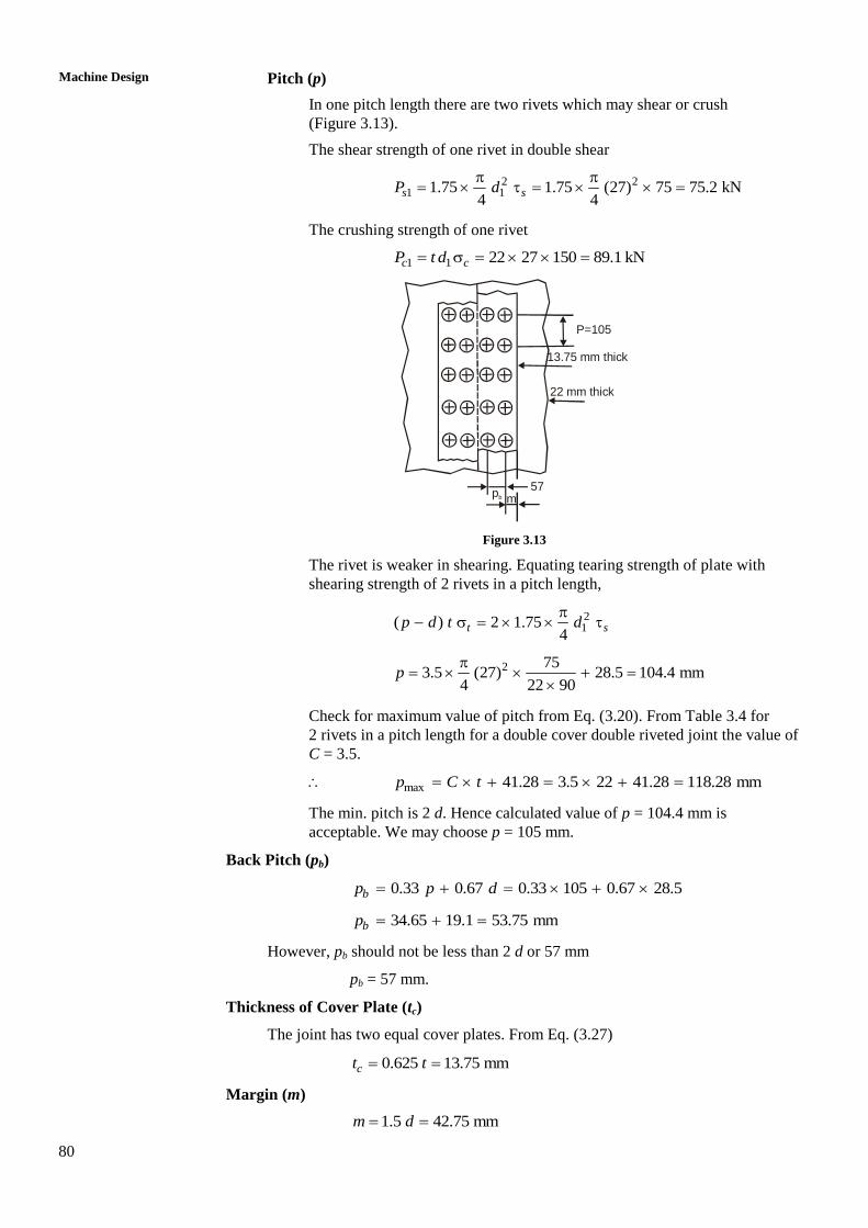
Pitch (p)
In one pitch length there are two rivets which may shear or crush
(Figure 3.13).
The shear strength of one rivet in double shear
2 21 11.75 1.75 (27) 75 75.2 kN
4 4s sP d
The crushing strength of one rivet
1 1 22 27 150 89.1 kNc cP t d
P=105
13.75 mm thick
22 mm thick
m57
pb
Figure 3.13
The rivet is weaker in shearing. Equating tearing strength of plate with
shearing strength of 2 rivets in a pitch length,
21( ) 2 1.75
4t sp d t d
2 753.5 (27) 28.5 104.4 mm
4 22 90p
Check for maximum value of pitch from Eq. (3.20). From Table 3.4 for
2 rivets in a pitch length for a double cover double riveted joint the value of
C = 3.5.
max 41.28 3.5 22 41.28 118.28 mmp C t
The min. pitch is 2 d. Hence calculated value of p = 104.4 mm is
acceptable. We may choose p = 105 mm.
Back Pitch (pb)
0.33 0.67 0.33 105 0.67 28.5bp p d
34.65 19.1 53.75 mmbp
However, pb should not be less than 2 d or 57 mm
pb = 57 mm.
Thickness of Cover Plate (tc)
The joint has two equal cover plates. From Eq. (3.27)
0.625 13.75 mmct t
Margin (m)
1.5 42.75 mm m d
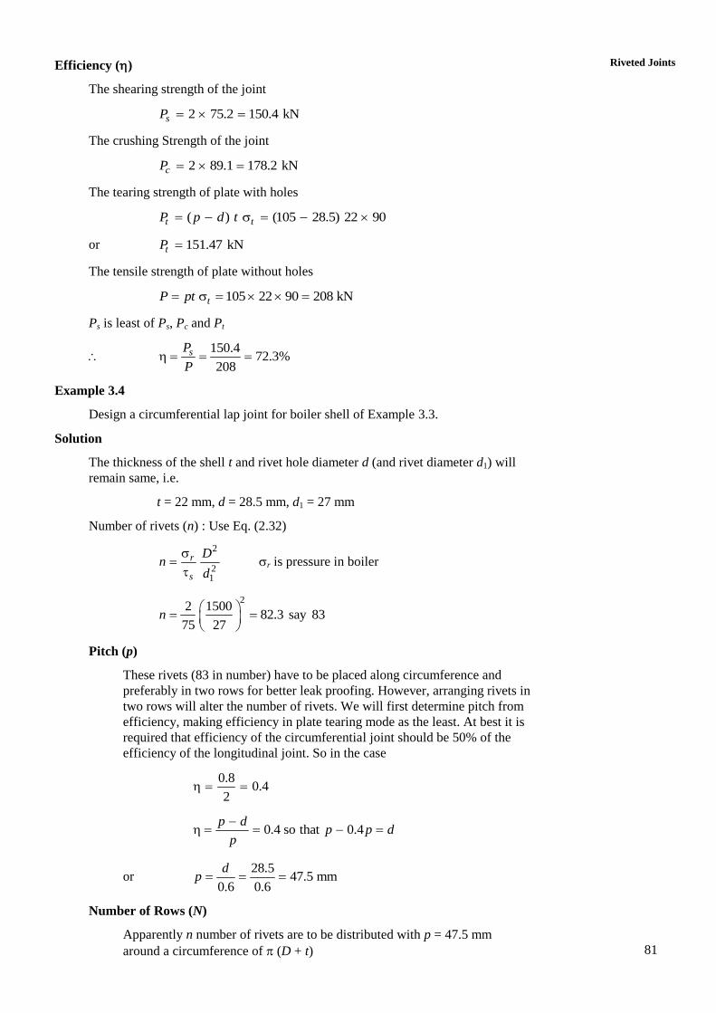
81
Riveted Joints Efficiency ()
The shearing strength of the joint
2 75.2 150.4 kNsP
The crushing Strength of the joint
2 89.1 178.2 kNcP
The tearing strength of plate with holes
( ) (105 28.5) 22 90t tP p d t
or 151.47 kNtP
The tensile strength of plate without holes
105 22 90 208 kNtP pt
Ps is least of Ps, Pc and Pt
150.4
72.3%208
sP
P
Example 3.4
Design a circumferential lap joint for boiler shell of Example 3.3.
Solution
The thickness of the shell t and rivet hole diameter d (and rivet diameter d1) will
remain same, i.e.
t = 22 mm, d = 28.5 mm, d1 = 27 mm
Number of rivets (n) : Use Eq. (2.32)
2
21
r
s
Dn
d r is pressure in boiler
22 1500
82.3 say 8375 27
n
Pitch (p)
These rivets (83 in number) have to be placed along circumference and
preferably in two rows for better leak proofing. However, arranging rivets in
two rows will alter the number of rivets. We will first determine pitch from
efficiency, making efficiency in plate tearing mode as the least. At best it is
required that efficiency of the circumferential joint should be 50% of the
efficiency of the longitudinal joint. So in the case
0.8
0.42
0.4 so that 0.4p d
p p dp
or 28.5
47.5 mm0.6 0.6
dp
Number of Rows (N)
Apparently n number of rivets are to be distributed with p = 47.5 mm
around a circumference of (D + t)
82
Machine Design
83 47.5
0.82(1500 28.5) 1528.5
n pN
To make N = 2 and keeping p = 47.5 mm, n will increase,
47.5
2 giving 2021528.5
nn
Now choosing n = 202 will alter p
2 1528.5
47.54 mm202
p
With number of rivets 2 per pitch length the constant C from Table 3.4 is
3.06 and using Eq. (3.20)
max 41.28 3.06 22 41.28 108.6 mmp Ct
But for convenience of caulking p should be at least 2 d.
p = 2 28.5 = 57 mm
This will further alter number of rivets as
2 1528.8
168.5 say 16857
n
So that 2 1528.8.5
57.16 mm168
p
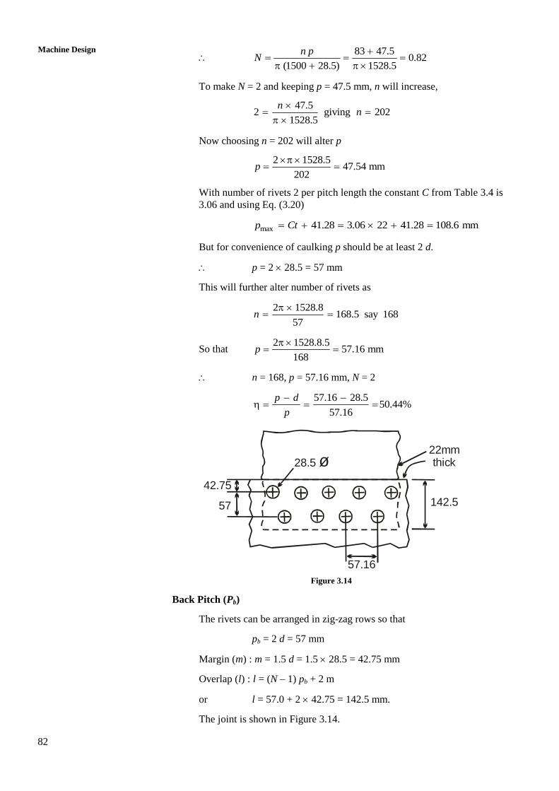
n = 168, p = 57.16 mm, N = 2
57.16 28.5
50.44%57.16
p d
p
42.75
57
28.5 ø22mm thick
142.5
57.16
Figure 3.14
Back Pitch (Pb)
The rivets can be arranged in zig-zag rows so that
pb = 2 d = 57 mm
Margin (m) : m = 1.5 d = 1.5 28.5 = 42.75 mm
Overlap (l) : l = (N – 1) pb + 2 m
or l = 57.0 + 2 42.75 = 142.5 mm.
The joint is shown in Figure 3.14.
83
Riveted Joints 3.13 TORSIONAL LOADING AND ECCENTRIC
LOADING OF RIVETED JOINT
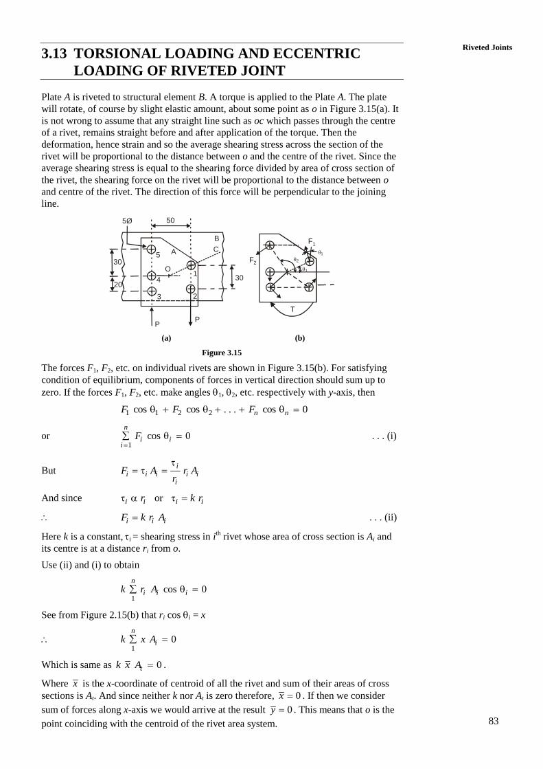
Plate A is riveted to structural element B. A torque is applied to the Plate A. The plate
will rotate, of course by slight elastic amount, about some point as o in Figure 3.15(a). It
is not wrong to assume that any straight line such as oc which passes through the centre
of a rivet, remains straight before and after application of the torque. Then the
deformation, hence strain and so the average shearing stress across the section of the
rivet will be proportional to the distance between o and the centre of the rivet. Since the
average shearing stress is equal to the shearing force divided by area of cross section of
the rivet, the shearing force on the rivet will be proportional to the distance between o
and centre of the rivet. The direction of this force will be perpendicular to the joining
line.
30
20
1
23
4
5
O
30
A
B
C
P
505Ø
P
F2
F1
T
1
1
2
(a) (b)
Figure 3.15
The forces F1, F2, etc. on individual rivets are shown in Figure 3.15(b). For satisfying
condition of equilibrium, components of forces in vertical direction should sum up to
zero. If the forces F1, F2, etc. make angles 1, 2, etc. respectively with y-axis, then
1 1 2 2cos cos . . . cos 0n nF F F
or 1
cos 0n
i ii
F . . . (i)
But i
i i i i ii
F A r Ar
And since ori i i ir k r
i i iF k r A . . . (ii)
Here k is a constant, i = shearing stress in ith rivet whose area of cross section is Ai and
its centre is at a distance ri from o.
Use (ii) and (i) to obtain
1
cos 0n
i i ik r A
See from Figure 2.15(b) that ri cos i = x
1
0n
ik x A
Which is same as 0tk x A .
Where x is the x-coordinate of centroid of all the rivet and sum of their areas of cross
sections is At. And since neither k nor At is zero therefore, 0x . If then we consider
sum of forces along x-axis we would arrive at the result 0y . This means that o is the
point coinciding with the centroid of the rivet area system.
84
Machine Design
Example 3.5
In Figure 3.15(a) the distances between columns and rows of rivets are shown.
Each rivet is 5 mm in diameter and force P = 1 kN. Calculate the maximum
shearing stress in rivet.
Solution
The five rivets have been numbered as 1, 2, . . . , 5. Take centre of rivet 3 as
origin and x and y axes along 32 and 35 respectively. Areas of all rivets is
2(5) 19.644
A
mm2. If x and y are the coordinates of the centroid, then
50 50 5A A A x
Hence, 20 mmx
Also, 50 20 30 5 , 20 mmA A A A y y
Hence centroid is on the horizontal line through rivet 4. We can calculate various
distances of rivet centres from centroid.
2 21 10 30 10 10 r
2 22 20 30 10 13r
2 23 20 20 10 8r
24 20 0 10 2r
2 25 30 20 10 13r
Now F1 = k r1 = k 10 10 , moment of F1 about O,
21 1 1000M k r k
2 2 10 13, F k r k 2 1300M k
1 11 2
2 2
10 10or
1313
F rF F
F r
We can find each of F1, F2, F3, F4 and F5 in terms of k or we can find each force in
terms of F2. We may like to choose F2 because F2 is grater than all other forces
because r2 is larger than all other r.
3 2 4 2 5 2
8 2, ,
13 13F F F F F F
Taking moments of all forces about O and equating with the applied moment of
50 P = 50000 N mm.
2 2
10 810 10 10 13
13 13 F F
42 2 2
210 8 10 2 10 13 5 10
13 F F F
42 2 2 2 2100 130 80 40 1305 10
13 13 13 13 13
F F F F F
2
500 13375.6 N
4.8F
Maximum shearing stress 22 375.619.12 N/mm
19.64
F
A
This stress will be in rivets 2 and 5.
85
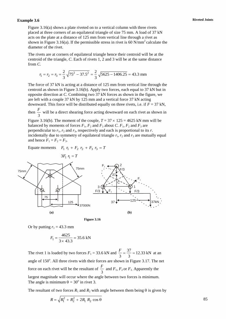
Riveted Joints Example 3.6
Figure 3.16(a) shows a plate riveted on to a vertical column with three rivets
placed at three corners of an equilateral triangle of size 75 mm. A load of 37 kN
acts on the plate at a distance of 125 mm from vertical line through a rivet as
shown in Figure 3.16(a). If the permissible stress in rivet is 60 N/mm2 calculate the
diameter of the rivet.
The rivets are at corners of equilateral triangle hence their centroid will be at the
centroid of the triangle, C. Each of rivets 1, 2 and 3 will be at the same distance
from C.
2 21 2 3
2 275 37.5 5625 1406.25 43.3 mm
3 3r r r
The force of 37 kN is acting at a distance of 125 mm from vertical line through the
centroid as shown in Figure 3.16(b). Apply two forces, each equal to 37 kN but in
opposite direction at C. Combining two 37 kN forces as shown in the figure, we
are left with a couple 37 kN by 125 mm and a vertical force 37 kN acting
downward. This force will be distributed equally on three rivets, i.e. if F = 37 kN,
then 3
F will be a direct shearing force acting downward on each rivet as shown in
Figure 3.16(b). The moment of the couple, T = 37 125 = 4625 kN mm will be
balanced by moments of forces F1, F2 and F3 about C. F1, F2 and F3 are
perpendicular to r1, r2 and r3, respectively and each is proportional to its r.
incidentally due to symmetry of equilateral triangle ri, r2 and r3 are mutually equal
and hence F1 = F2 = F3.
Equate moments 1 1 2 2 3 3F r F r F r T
1 13F r T
75mm75mm
75
12537000N
1
2
3
37
C
F2
F3
F/3
F/3F/3
37 37kN125
F1
(a) (b)
Figure 3.16
Or by putting r1 = 43.3 mm
1
462535.6 kN
3 43.3F
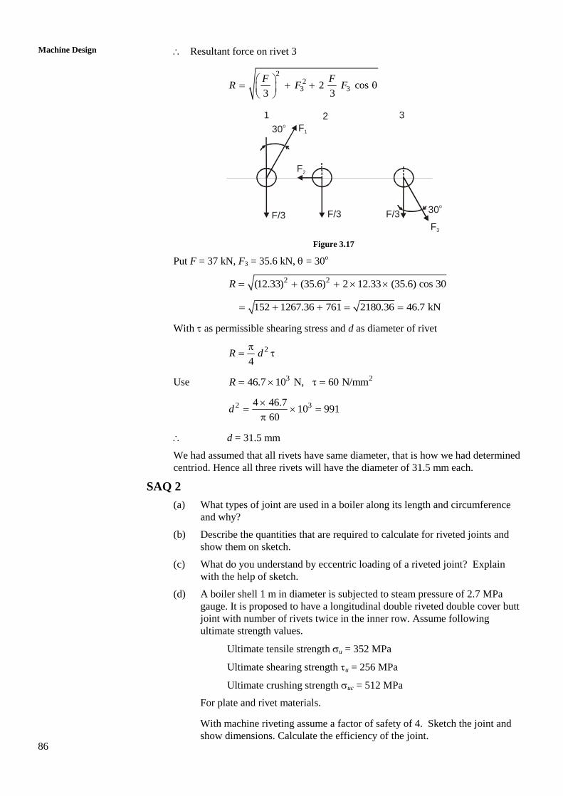
The rivet 1 is loaded by two forces F1 = 33.6 kN and 37
12.33 kN3 3
F at an
angle of 150o. All three rivets with their forces are shown in Figure 3.17. The net
force on each rivet will be the resultant of 3
F and F1, F2 or F3. Apparently the
largest magnitude will occur where the angle between two forces is minimum.
The angle is minimum = 30o in rivet 3.
The resultant of two forces R1 and R2 with angle between them being is given by
2 21 2 1 22 cos R R R R R
86
Machine Design
Resultant force on rivet 3
22
3 32 cos3 3
F FR F F
1 2 3
30o
30o
F/3 F/3F/3
F1
F2
F3
Figure 3.17
Put F = 37 kN, F3 = 35.6 kN, = 30o
2 2(12.33) (35.6) 2 12.33 (35.6) cos 30 R
152 1267.36 761 2180.36 46.7 kN
With as permissible shearing stress and d as diameter of rivet
2
4R d
Use 3 246.7 10 N, 60 N/mmR
2 34 46.710 991
60d
d = 31.5 mm
We had assumed that all rivets have same diameter, that is how we had determined
centriod. Hence all three rivets will have the diameter of 31.5 mm each.
SAQ 2
(a) What types of joint are used in a boiler along its length and circumference
and why?
(b) Describe the quantities that are required to calculate for riveted joints and
show them on sketch.
(c) What do you understand by eccentric loading of a riveted joint? Explain
with the help of sketch.
(d) A boiler shell 1 m in diameter is subjected to steam pressure of 2.7 MPa
gauge. It is proposed to have a longitudinal double riveted double cover butt
joint with number of rivets twice in the inner row. Assume following
ultimate strength values.
Ultimate tensile strength u = 352 MPa
Ultimate shearing strength u = 256 MPa
Ultimate crushing strength uc = 512 MPa
For plate and rivet materials.
With machine riveting assume a factor of safety of 4. Sketch the joint and
show dimensions. Calculate the efficiency of the joint.
87
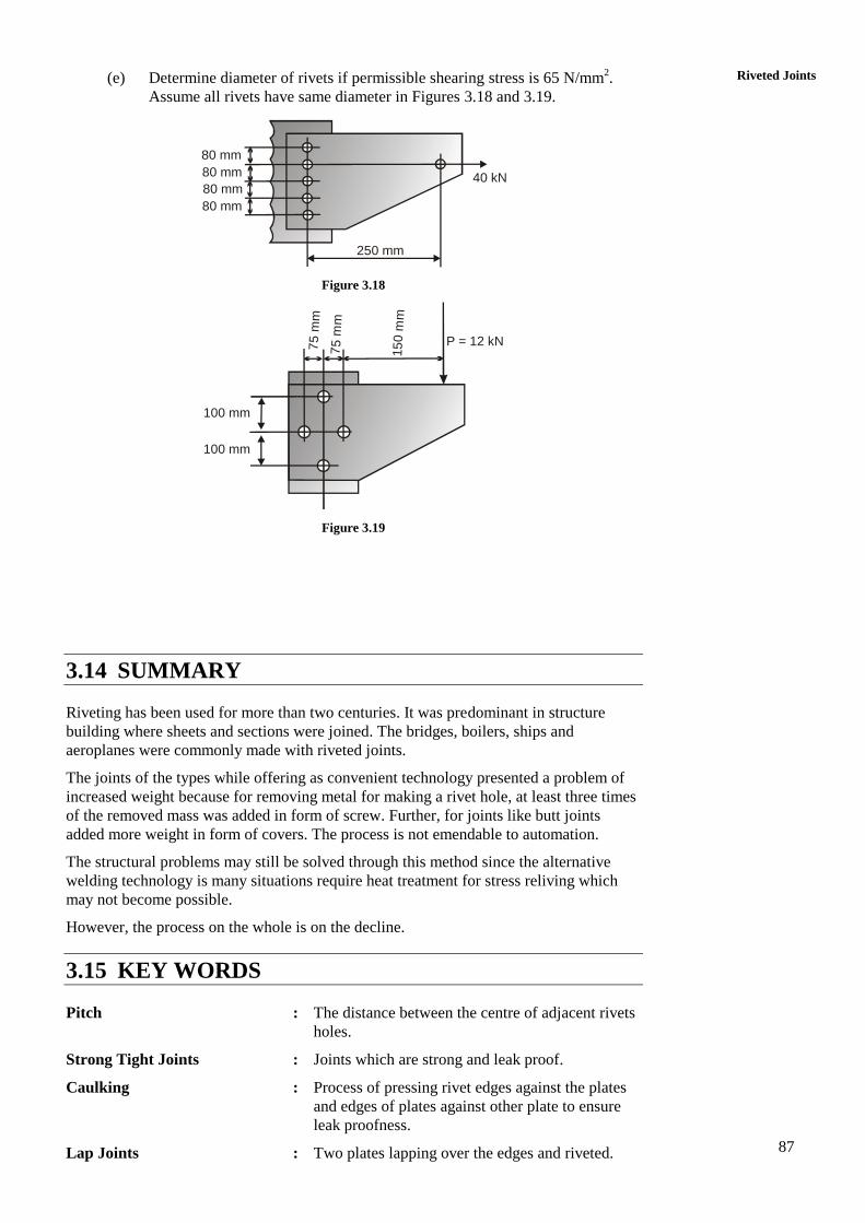
Riveted Joints (e) Determine diameter of rivets if permissible shearing stress is 65 N/mm2.
Assume all rivets have same diameter in Figures 3.18 and 3.19.
80 mm
80 mm
80 mm
80 mm
250 mm
40 kN
Figure 3.18
100 mm
100 mm
75 m
m
75
mm
15
0 m
m
P = 12 kN
Figure 3.19
3.14 SUMMARY
Riveting has been used for more than two centuries. It was predominant in structure
building where sheets and sections were joined. The bridges, boilers, ships and
aeroplanes were commonly made with riveted joints.
The joints of the types while offering as convenient technology presented a problem of
increased weight because for removing metal for making a rivet hole, at least three times
of the removed mass was added in form of screw. Further, for joints like butt joints
added more weight in form of covers. The process is not emendable to automation.
The structural problems may still be solved through this method since the alternative
welding technology is many situations require heat treatment for stress reliving which
may not become possible.
However, the process on the whole is on the decline.
3.15 KEY WORDS
Pitch : The distance between the centre of adjacent rivets
holes.
Strong Tight Joints : Joints which are strong and leak proof.
Caulking : Process of pressing rivet edges against the plates
and edges of plates against other plate to ensure
leak proofness.
Lap Joints : Two plates lapping over the edges and riveted.
88
Machine Design
Butt Joint : Two plates buttering along the edges, covered
with straps and riveted.
Failure Modes : The riveted joint may fail due to fail of plate or
rivet. Each failure is due to a particular stress.
Combination of stress and part defines the mode.
Efficiency : The ratio of least load carrying capacity to the
strength of solid plate.
3.16 ANSWERS TO SAQs
SAQ 1
(e) Follow the method of Example 3.11, Section 3.11 and determine
d = 19.5 mm, d1 = 18 mm
Width of plate = 130 mm
Number of rivets = 5
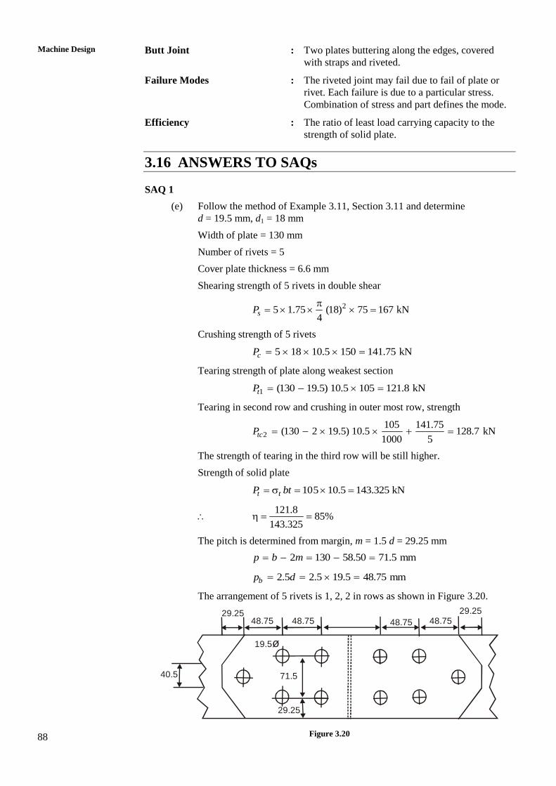
Cover plate thickness = 6.6 mm
Shearing strength of 5 rivets in double shear
25 1.75 (18) 75 167 kN4
sP
Crushing strength of 5 rivets
5 18 10.5 150 141.75 kNcP
Tearing strength of plate along weakest section
1 (130 19.5) 10.5 105 121.8 kNtP
Tearing in second row and crushing in outer most row, strength
2
105 141.75(130 2 19.5) 10.5 128.7 kN
1000 5tcP
The strength of tearing in the third row will be still higher.
Strength of solid plate
105 10.5 143.325 kNt tP bt
121.8
85%143.325
The pitch is determined from margin, m = 1.5 d = 29.25 mm
2 130 58.50 71.5 mmp b m
2.5 2.5 19.5 48.75 mmbp d
The arrangement of 5 rivets is 1, 2, 2 in rows as shown in Figure 3.20.
29.2548.75 48.75 48.75 48.75
29.25
40.5
19.5ø
71.5
29.25
Fig. 6.29
Figure 3.20
89
Riveted Joints SAQ 2
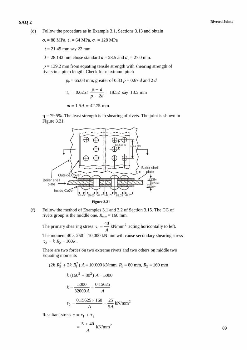
(d) Follow the procedure as in Example 3.1, Sections 3.13 and obtain
t = 88 MPa, s = 64 MPa, c = 128 MPa
t = 21.45 mm say 22 mm
d = 28.142 mm chose standard d = 28.5 and d1 = 27.0 mm.
p = 139.2 mm from equating tensile strength with shearing strength of
rivets in a pitch length. Check for maximum pitch
pb = 65.03 mm, greater of 0.33 p + 0.67 d and 2 d
0.625 18.52 say 18.5 mm2
c
p dt t
p d
1.5 42.75 mmm d
= 79.5%. The least strength is in shearing of rivets. The joint is shown in
Figure 3.21.
Outside Cover
Boiler shell plate
Inside Cover
42.7542.75 42.75 42.7565.03 65.03
18.5 mm
18.5 mm
22 mm
Boiler shell plate
69.6 mm 139.2 mm
Figure 3.21
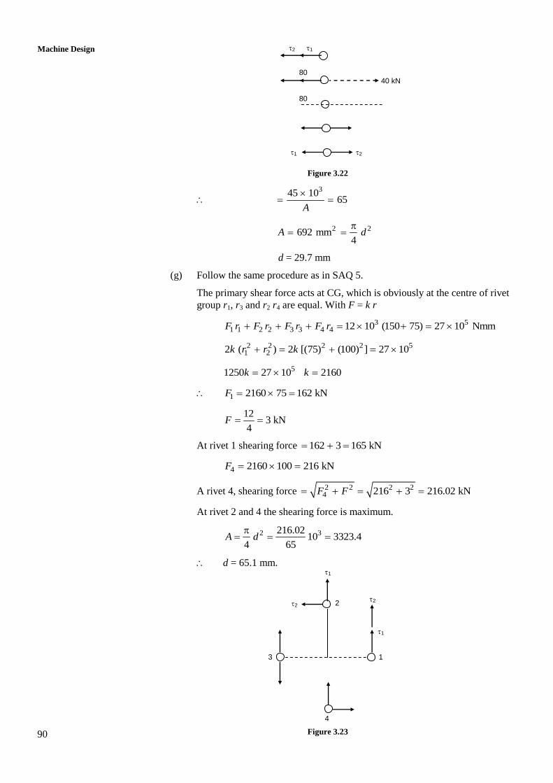
(f) Follow the method of Examples 3.1 and 3.2 of Section 3.15. The CG of
rivets group is the middle one. Rmax = 160 mm.
The primary shearing stress 21
40kN/mm
A acting horicontally to left.
The moment 40 250 = 10,000 kN mm will cause secondary shearing stress
2 2 160k R k .
There are two forces on two extreme rivets and two others on middle two
Equating moments
2 22 1 1 2(2 2 ) 10,000 kNmm, 80 mm, 160 mm k R k R A R R
2 2(160 80 ) 5000 k A
5000 0.15625
32000 k
A A
22
0.15625 160 25kN/mm
5A A
Resultant stress 1 2
25 40kN/mm
A
90
Machine Design
Figure 3.22
345 10
65A
2 2692 mm4
A d
d = 29.7 mm
(g) Follow the same procedure as in SAQ 5.
The primary shear force acts at CG, which is obviously at the centre of rivet
group r1, r3 and r2 r4 are equal. With F = k r
3 51 1 2 2 3 3 4 4 12 10 (150 75) 27 10 NmmF r F r F r F r
2 2 2 2 51 22 ( ) 2 [(75) (100) ] 27 10k r r k
51250 27 10 2160k k
1 2160 75 162 kNF
12
3 kN4
F
At rivet 1 shearing force 162 3 165 kN
4 2160 100 216 kNF
A rivet 4, shearing force 2 2 2 24 216 3 216.02 kNF F
At rivet 2 and 4 the shearing force is maximum.
2 3216.0210 3323.4
4 65A d
d = 65.1 mm.
Figure 3.23
2 1
80
80
40 kN
2 1
1
2 2
1
2
3
4
1