Unit 3 Flow Measurement - WordPress.com · Bernoulli’s theorem •BERNOULLI'S PRINCIPLE: An...
117
Unit 3 Flow Measurement Process Instrumentation I
Transcript of Unit 3 Flow Measurement - WordPress.com · Bernoulli’s theorem •BERNOULLI'S PRINCIPLE: An...
Unit 3 Flow MeasurementProcess Instrumentation I
Introduction to flow measurement
• Flow measurement is essential in many industries such as the oil, power, chemical, food, water, and waste treatment industries.
• These industries require the determination of the quantity of a fluid, either gas, liquid, or steam, that passes through a check point, either a closed conduit or an open channel, in their daily processing or operating.
• The quantity to be determined may be volume flow rate, mass flow rate, flow velocity, or other quantities related to the previous three.
• The instrument to conduct flow measurement is called flowmeter.
02-Apr-18 UNIT 3 FLOW MEASUREMENT 2
Introduction to flow measurement
Units of Flow
• The units used to describe the flow measured can be of several types depending on how the specific process needs the information.
• Solids: Normally expressed in weight rate like Tones/hour, Kg/minute etc.
• Liquid: Expressed both in weight rate and in volume rate.
• Examples: Tones/hour, Kg/minute, liters/hour, liters/minute, m3/hour etc.
• Gases: Expressed in volume rate at NTP (Natural Temperature (20°C) and Pressure (760 mm Hg)) or STP (Standard (0°C) Temperature and Pressure (760 mm Hg)) like m3/hour, Nm3/hour etc. Steam. Expressed in weight rate like Tones/hour, Kg/minutes etc.
02-Apr-18 UNIT 3 FLOW MEASUREMENT 3
Flow measurement terminologies:
• Specific Gravity: The specific gravity is the ratio between the density of an object, and a reference substance.
• Density: It is defined as mass per unit volume.
ρ=m/V
• Viscosity: Viscosity is defined as the resistance to flow of liquid.• Viscosity is often referred to as the thickness of a fluid. You can think of water
(low viscosity) and honey (high viscosity).
• Compressibility: Compressibility is a measure of the relative volume change of a fluid or solid as a response to a pressure change.
02-Apr-18 UNIT 3 FLOW MEASUREMENT 4
Flow measurement terminologies:
Mass Flow rate and Volumetric Flow rate
• 𝑀𝑎𝑠𝑠 𝐹𝑙𝑜𝑤 𝑅𝑎𝑡𝑒 =𝑀𝑎𝑠𝑠
𝑇𝑖𝑚𝑒; 𝑞𝑚 =
𝑚
𝑡(𝑘𝑔
𝑠,𝑔
𝑠,𝑘𝑔
ℎ)
• 𝑉𝑜𝑙𝑢𝑚𝑒 𝐹𝑙𝑜𝑤 𝑅𝑎𝑡𝑒 =𝑉𝑜𝑙𝑢𝑚𝑒
𝑇𝑖𝑚𝑒; 𝑞𝑣 =
𝑉
𝑡(𝑚3
𝑠,𝑙
𝑠,𝑚3
ℎ)
Effect of pressure and temperature on flow measurement. • Gases are compressible and change its volume when placed under
pressure, are heated or are cooled. In gas flow measurement, the density of the gas changes as pressure and temperature change. This change in density can affect the accuracy of the measured flow rate if it is uncompensated.
• Liquids are incompressible and does not change its volume when placed under pressure, but change its volume when liquids are heated or cooled
02-Apr-18 UNIT 3 FLOW MEASUREMENT 5
Equation of Continuity
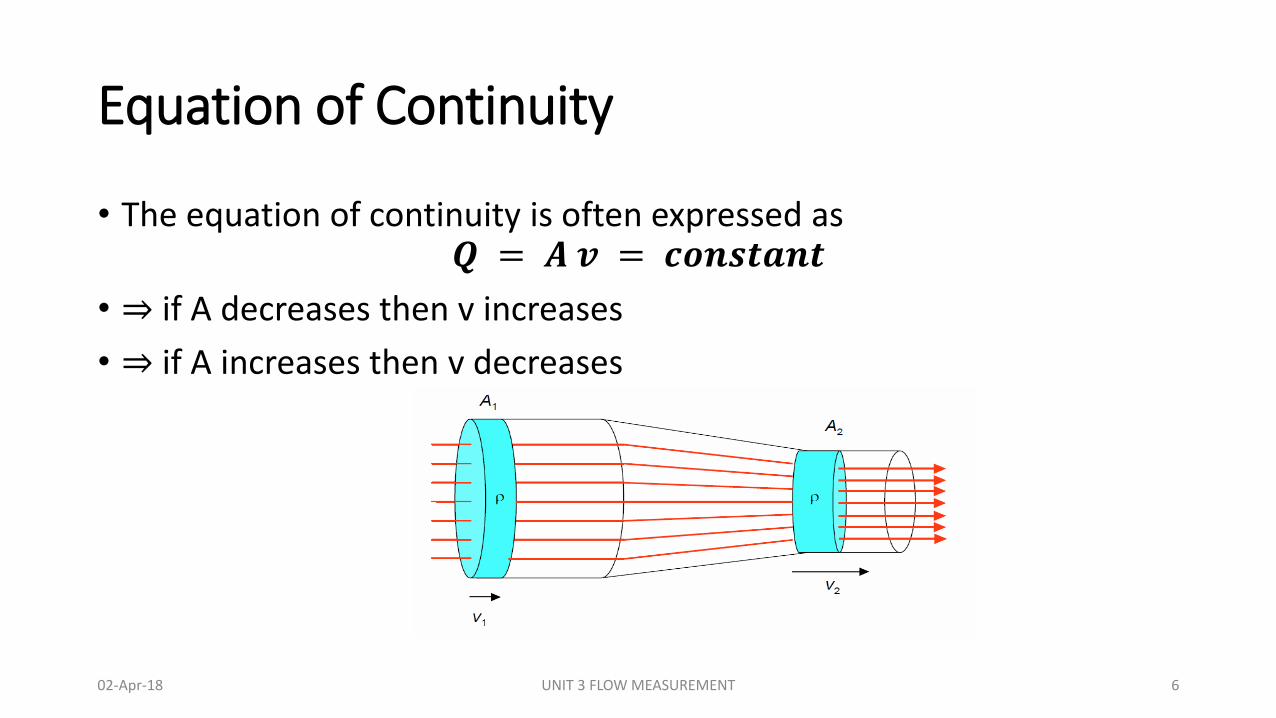
• The equation of continuity is often expressed as𝑸 = 𝑨 𝒗 = 𝒄𝒐𝒏𝒔𝒕𝒂𝒏𝒕
• ⇒ if A decreases then v increases
• ⇒ if A increases then v decreases
02-Apr-18 UNIT 3 FLOW MEASUREMENT 6
Bernoulli’s theorem
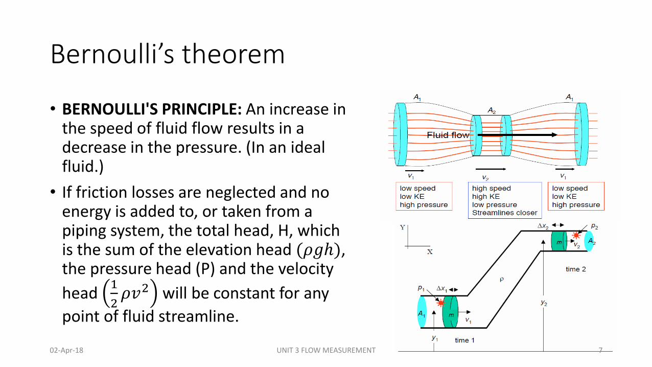
• BERNOULLI'S PRINCIPLE: An increase in the speed of fluid flow results in a decrease in the pressure. (In an ideal fluid.)
• If friction losses are neglected and no energy is added to, or taken from a piping system, the total head, H, which is the sum of the elevation head (𝜌𝑔ℎ), the pressure head (P) and the velocity
head 1
2𝜌𝑣2 will be constant for any
point of fluid streamline.
02-Apr-18 UNIT 3 FLOW MEASUREMENT 7
Bernoulli’s theorem
• Consider conservation of energy
Work done = kinetic energy + potential energy∆𝑊 = ∆𝐾 + ∆𝑈
• Now from pressure P=F/A, we have F=PA
• Therefore W=PAd
• So, the positive work done on our system by the water near point 1 will be 𝑊1 =𝑃1𝐴1𝑑1 And the work done by the water near point 2 will be 𝑊2 = 𝑃2𝐴2𝑑2
• But the terms A1d1 and A2d2 have to be equal since they represent the volumes of the fluid displaced near point 1 and point 2.
𝑉 = 𝐴1𝑑1 = 𝐴2𝑑2
• Therefore work done will be 𝑃1𝑉 − 𝑃2𝑉 = 𝛥𝐾 + 𝛥𝑈
02-Apr-18 UNIT 3 FLOW MEASUREMENT 8
Bernoulli’s theorem
• Now we'll substitute in the formulas for kinetic energy 𝐾 =1
2𝑚𝑣2
and gravitational potential energy 𝑈 = 𝑚𝑔ℎ to get,
𝑃1𝑉 − 𝑃2𝑉 = (1
2𝑚2𝑣2
2 +𝑚2𝑔ℎ2) − (1
2𝑚1𝑣1
2 +𝑚1𝑔ℎ1)
• In this equation P1 and P2 represent the pressures of the fluid in volumes 1 and 2 respectively. The variables v1 and v2 represent the speeds of the fluid in volumes 1 and 2 respectively. And h1 (or y1) and h2 (or y2) represent the height of the fluid in volumes 1 and 2 respectively.
02-Apr-18 UNIT 3 FLOW MEASUREMENT 9
Bernoulli’s theorem
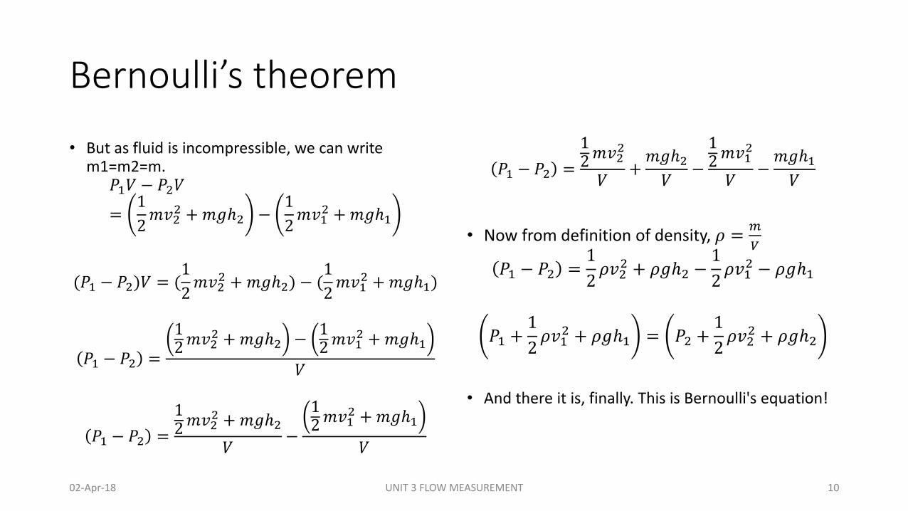
• But as fluid is incompressible, we can write m1=m2=m.
𝑃1𝑉 − 𝑃2𝑉
=1
2𝑚𝑣2
2 +𝑚𝑔ℎ2 −1
2𝑚𝑣1
2 +𝑚𝑔ℎ1
(𝑃1 − 𝑃2)𝑉 = (1
2𝑚𝑣2
2 +𝑚𝑔ℎ2) − (1
2𝑚𝑣1
2 +𝑚𝑔ℎ1)
𝑃1 − 𝑃2 =
12𝑚𝑣2
2 +𝑚𝑔ℎ2 −12𝑚𝑣1
2 +𝑚𝑔ℎ1
𝑉
𝑃1 − 𝑃2 =
12𝑚𝑣2
2 +𝑚𝑔ℎ2
𝑉−
12𝑚𝑣1
2 +𝑚𝑔ℎ1
𝑉
𝑃1 − 𝑃2 =
12𝑚𝑣2
2
𝑉+𝑚𝑔ℎ2𝑉
−
12𝑚𝑣1
2
𝑉−𝑚𝑔ℎ1𝑉
• Now from definition of density, 𝜌 =𝑚
𝑉
𝑃1 − 𝑃2 =1
2𝜌𝑣2
2 + 𝜌𝑔ℎ2 −1
2𝜌𝑣1
2 − 𝜌𝑔ℎ1
𝑃1 +1
2𝜌𝑣1
2 + 𝜌𝑔ℎ1 = 𝑃2 +1
2𝜌𝑣2
2 + 𝜌𝑔ℎ2
• And there it is, finally. This is Bernoulli's equation!
02-Apr-18 UNIT 3 FLOW MEASUREMENT 10
Turbulent and Laminar Flow
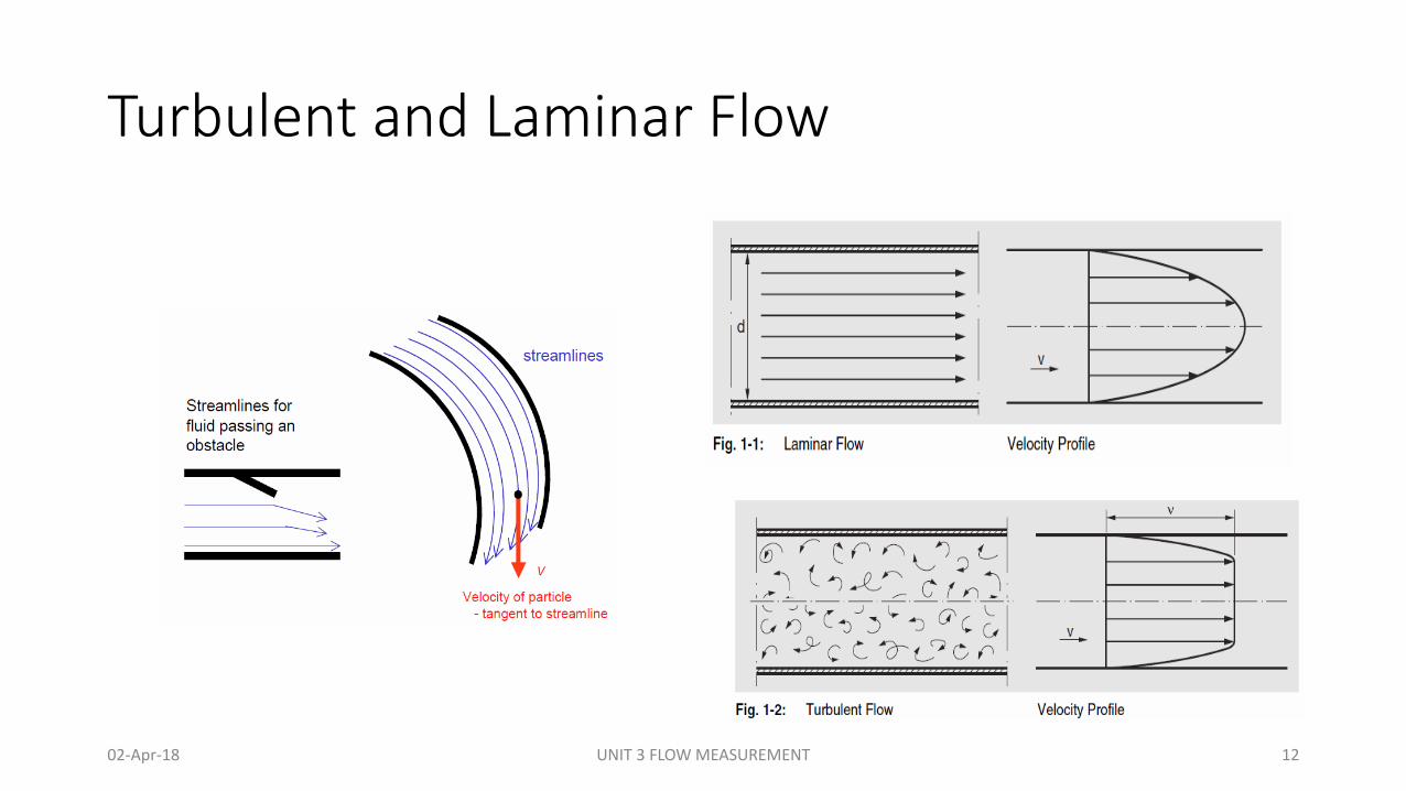
• If the velocity of fluid inside the pipe is small, streamlines will be in straight parallel lines. As the velocity of fluid inside the pipe gradually increase, streamlines will continue to be straight and parallel with the pipe wall until velocity is reached when the streamlines will waver and suddenly break into diffused patterns. The velocity at which this occurs is called "critical velocity". At velocities higher than "critical", the streamlines are dispersed at random throughout the pipe.
• The regime of flow when velocity is lower than "critical" is called laminar flow (or viscous or streamline flow). At laminar regime of flow the velocity is highest on the pipe axis, and on the wall the velocity is equal to zero.
• When the velocity is greater than "critical", the regime of flow is turbulent. In turbulent regime of flow there is irregular random motion of fluid particles in directions transverse to the direction on main flow. Velocity change in turbulent flow is more uniform than in laminar.
• Transitional Flow is type of flow, in which both types of flow may be present at different points along the pipe line or the flow may switch between the laminar and turbulence.
02-Apr-18 UNIT 3 FLOW MEASUREMENT 11
Turbulent and Laminar Flow
02-Apr-18 UNIT 3 FLOW MEASUREMENT 12
What is Reynolds’s number?
• Osborne Reynolds states that the nature of flow in pipe, is depending on the pipe diameter, the density and viscosity of the flowing fluid and the velocity of the flow.
• Reynold’s number is a dimensionless quantity that is used to determine the type of flow pattern as laminar or turbulent while flowing through a pipe. Reynold’s number is defined by the ratio of inertial forces to that of viscous forces. It is given by the following relation
𝑅𝑒𝑦𝑛𝑜𝑙𝑑𝑠𝑁𝑢𝑚𝑏𝑒𝑟 =𝐼𝑛𝑒𝑟𝑡𝑖𝑎𝑙𝐹𝑜𝑟𝑐𝑒
𝑉𝑖𝑠𝑐𝑜𝑢𝑠𝐹𝑜𝑟𝑐𝑒𝑅𝑒 = 𝜌𝑉𝐷/𝜇
• where, Re is the Reynold’s number, ρ is the density of the fluid, V is the velocity of flow, D is the pipe diameter, μ is the viscosity of the fluid
02-Apr-18 UNIT 3 FLOW MEASUREMENT 13
What is Reynolds’s number?
If Reynold’s number calculated is
• high (greater than 4000), then the flow through the pipe is said to be turbulent.
• low (less than 2000), the flow is said to be laminar.
• Numerically, these are acceptable values, but generally, laminar and turbulent flows are classified according to a range. Laminar flow falls below Reynold’s number of 1100 and turbulent falls in a range greater than 2200. For transitional flow, Reynolds number falls between 2000 an 4000.
02-Apr-18 UNIT 3 FLOW MEASUREMENT 14
Differential Flow sensing elements: Orifice
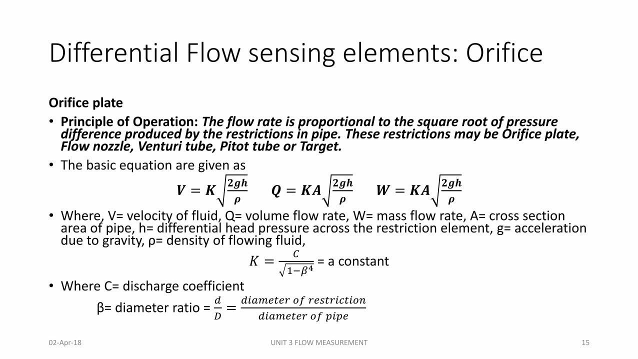
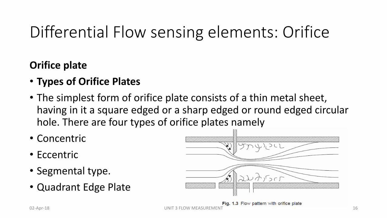
Orifice plate
• Principle of Operation: The flow rate is proportional to the square root of pressure difference produced by the restrictions in pipe. These restrictions may be Orifice plate, Flow nozzle, Venturi tube, Pitot tube or Target.
• The basic equation are given as
𝑽 = 𝑲𝟐𝒈𝒉
𝝆𝑸 = 𝑲𝑨
𝟐𝒈𝒉
𝝆𝑾 = 𝑲𝑨
𝟐𝒈𝒉
𝝆
• Where, V= velocity of fluid, Q= volume flow rate, W= mass flow rate, A= cross section area of pipe, h= differential head pressure across the restriction element, g= acceleration due to gravity, ρ= density of flowing fluid,
𝐾 =𝐶
1−𝛽4= a constant
• Where C= discharge coefficient
β= diameter ratio = 𝑑
𝐷=
𝑑𝑖𝑎𝑚𝑒𝑡𝑒𝑟 𝑜𝑓 𝑟𝑒𝑠𝑡𝑟𝑖𝑐𝑡𝑖𝑜𝑛
𝑑𝑖𝑎𝑚𝑒𝑡𝑒𝑟 𝑜𝑓 𝑝𝑖𝑝𝑒
02-Apr-18 UNIT 3 FLOW MEASUREMENT 15
Differential Flow sensing elements: Orifice
Orifice plate
• Types of Orifice Plates
• The simplest form of orifice plate consists of a thin metal sheet, having in it a square edged or a sharp edged or round edged circular hole. There are four types of orifice plates namely
• Concentric
• Eccentric
• Segmental type.
• Quadrant Edge Plate
02-Apr-18 UNIT 3 FLOW MEASUREMENT 16
Differential Flow sensing elements: ConcentricOrifice
02-Apr-18 UNIT 3 FLOW MEASUREMENT 17
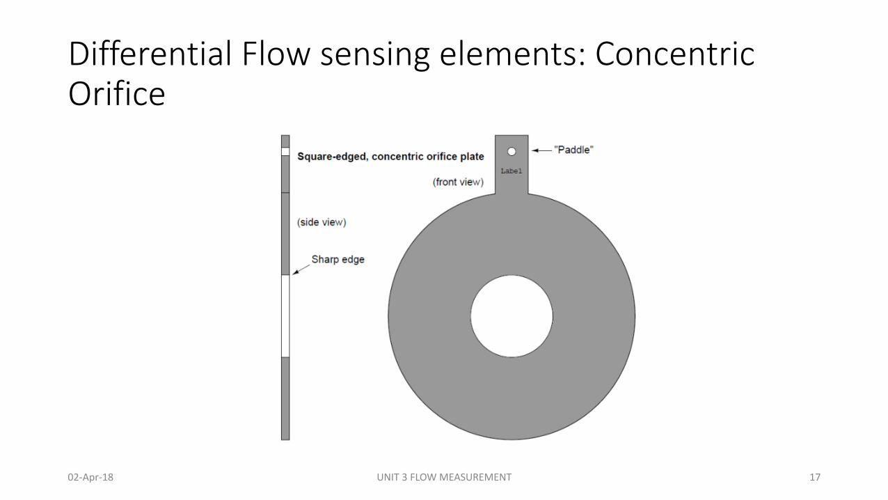
Differential Flow sensing elements: Concentric Orifice• The simplest design of orifice plate is the concentric orifice. This type of orifice
plate is manufactured by machining a precise, straight hole in the middle of a thin metal plate.
• Looking at a side view of a concentric orifice plate reveals sharp edges (90o corners) at the hole. A text label printed on the “paddle” of any orifice plate customarily identifies the upstream side of that plate, but in the case of the square-edged orifice plate it does not matter.
• It is also made from other materials such as nickel, monel, phosphor bronze, etc. to withstand the corrosive effect of the fluid.
• The plate thickness at the orifice edge should not exceed any of the following:• D/50• d/8• (D-d)/8
• Where d = the pipe internal diameter, D = the orifice diameter or bore
02-Apr-18 UNIT 3 FLOW MEASUREMENT 18
Differential Flow sensing elements: Concentric OrificeApplication:
• Used primarily for clean homogeneous liquids, gases, non-viscous fluids.
02-Apr-18 UNIT 3 FLOW MEASUREMENT 19
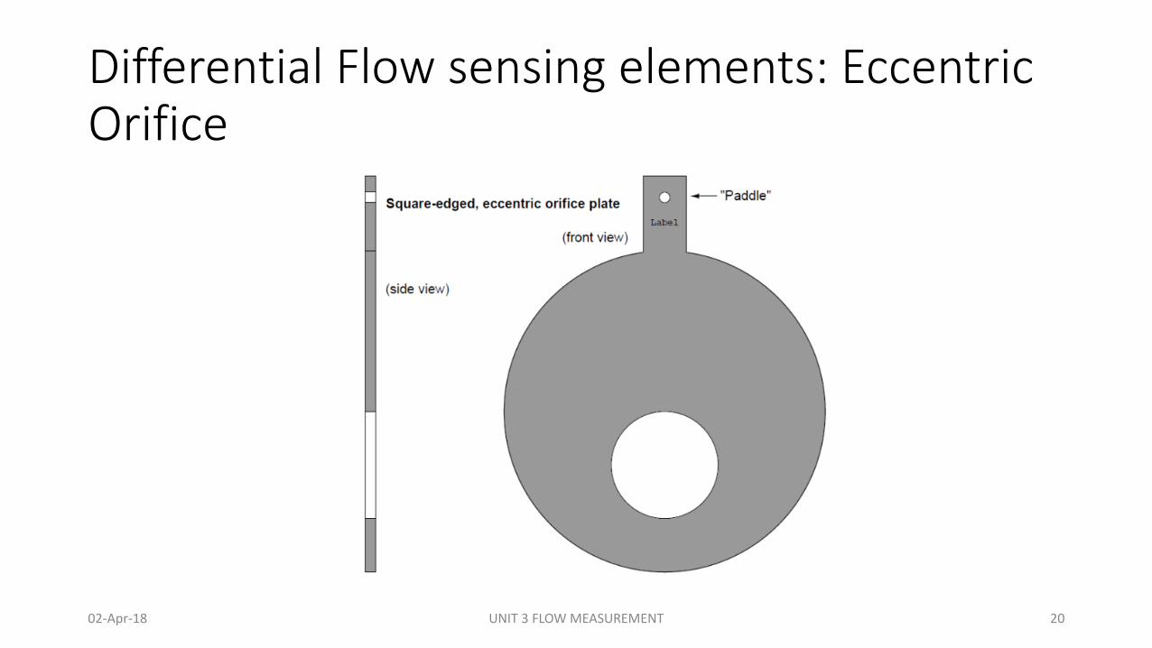
Differential Flow sensing elements: EccentricOrifice
02-Apr-18 UNIT 3 FLOW MEASUREMENT 20
Differential Flow sensing elements: Eccentric Orifice• Here the hole is located off-center to allow the undesired portions of the
fluid to pass through the orifice rather than build up on the upstream face. • For gas flows, the hole should be offset downward, so any liquid droplets
or solid particles may easily pass through. For liquid flows, the hole should be offset upward to allow gas bubbles to pass through and offset downward to allow heavy solids to pass through.
• An alternative to offsetting or re-shaping the bore hole of an orifice plate is to simply drill a small hole near the edge of the plate, flush with the inside diameter of the pipe, allowing undesired substances to pass through the plate rather than collect on the upstream side.
• If such a hole is oriented upward to pass vapor bubbles, it is called a vent hole. If the hole is oriented downward to pass liquid droplets or solids, it is called a drain hole.
02-Apr-18 UNIT 3 FLOW MEASUREMENT 21
Differential Flow sensing elements: Eccentric OrificeApplication:
• Used for measurement of flow for fluids containing solids and slurries.
• It is also used for vapors and gases where condensation is present.
02-Apr-18 UNIT 3 FLOW MEASUREMENT 22
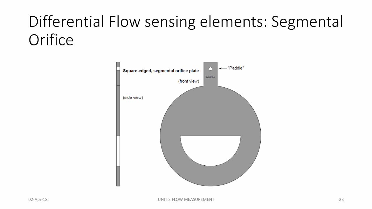
Differential Flow sensing elements: Segmental Orifice
02-Apr-18 UNIT 3 FLOW MEASUREMENT 23
Differential Flow sensing elements: Segmental Orifice• The second off-center orifice plate type is called the segmental orifice
plate, where the hole is not circular but rather just a segment of a concentric circle.
• As with the eccentric orifice plate design, the segmental hole should be offset downward in gas flow applications and either upward or downward in liquid flow applications depending on the type of undesired material(s) in the flow stream.
• Application:• This type is used primarily for slurries or extremely dirty gases where the flow
may contain impurities heavier than the fluid.
02-Apr-18 UNIT 3 FLOW MEASUREMENT 24
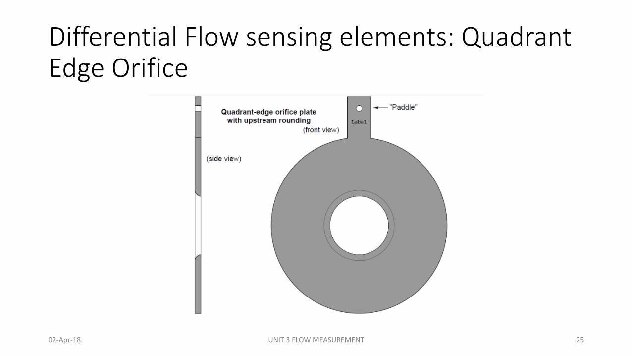
Differential Flow sensing elements: Quadrant Edge Orifice
02-Apr-18 UNIT 3 FLOW MEASUREMENT 25
Differential Flow sensing elements: Quadrant Edge Orifice• This orifice plates employ non-square-edged holes for the purpose of improving
performance at low Reynolds number values, where the effects of fluid viscosity are more apparent.
• It employs rounded- or conical-entrance holes in an effort to minimize the effects of fluid viscosity.
• Experiments have shown that decreased Reynolds number in a venturi-type flow element causes an increase in differential pressure due to the effects of friction against the entrance cone walls.
• By manufacturing an orifice plate in such a way that the hole exhibits “venturi-like” properties (i.e. a dull edge where the fast-moving fluid stream has more contact with the plate), these two effects tend to cancel each other, resulting in an orifice plate that maintains consistent accuracy at lower flow rates and/or higher viscosities than the simple square-edged orifice.
02-Apr-18 UNIT 3 FLOW MEASUREMENT 26
Differential Flow sensing elements: Quadrant Edge OrificeApplication:
• Used for high viscous fluids such as heavy crude, syrups and slurries. It is always recommended for flow where Reynolds number is less than 10,000.
02-Apr-18 UNIT 3 FLOW MEASUREMENT 27

Differential Flow sensing elements: Orifice
• Advantages:
• Orifices are small plates and easy to install/remove.
• Offer very little pressure drop.
• Orifice meter can be easily maintained.
• Measures a wide range of flow rates.
• They have a simple construction.
• They have easily fitted between flanges.
• They are most suitable for most gases and liquids.
• They are inexpensive.
• Around 65% of pressure drop can be recovered.
• Disadvantages:
• Requires homogeneous fluid.
• Requires single phase liquid.
• Causes a pressure drop in fluid.
• Their accuracy is affected by density, pressure and viscosity fluid.
• Fluid viscosity limits measuring range.
• Requires straight pipe runs to ensure accuracy is maintained.
• Pipe line must be fully especially for liquid flow measurement.
• They have low range ability.
02-Apr-18 UNIT 3 FLOW MEASUREMENT 28
Differential Flow sensing elements: flow nozzle
02-Apr-18 UNIT 3 FLOW MEASUREMENT 29
Differential Flow sensing elements: flow nozzleConstruction and Working:
• The flow nozzles are used for flow measurements at high fluid velocities and are more rugged and more resistant to erosion than the sharp edged orifice plate.
• Basically, there are two types of flow nozzles, the long-radius flow nozzles and the I.S.A. (International Federation of the National Standardizing Associations) flow nozzle.
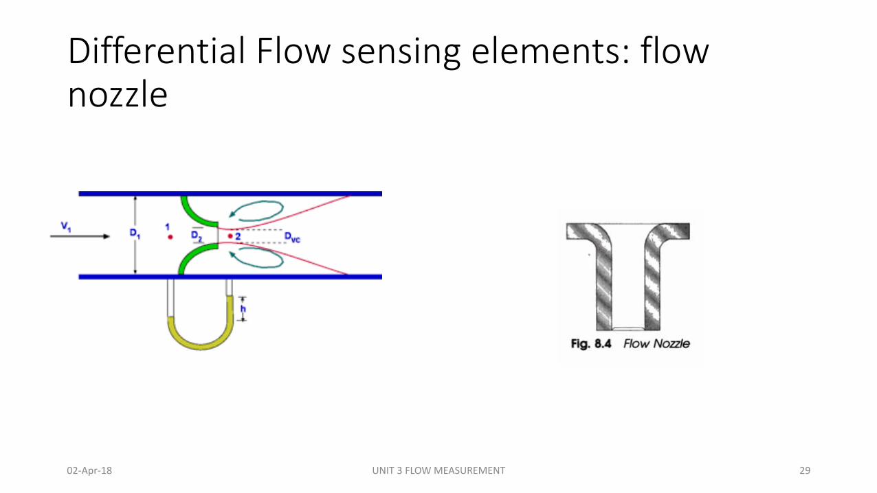
• A flow nozzle consists of a convergent inlet whose shape is a quarter ellipse, and a cylindrical throat, as shown in Fig. 8.4.
• Differential pressure measurement taps are normally located one pipe diameter upstream and one-half diameter downstream from the inlet faces of the nozzle.
• For a given diameter and a given differential pressure, it allows measurement of flow rates almost 65% more than that of the orifice plate.
02-Apr-18 UNIT 3 FLOW MEASUREMENT 30
Differential Flow sensing elements: flow nozzle• Flow nozzles are manufactured commonly from materials such as
stainless steel or chrome-moly steel.
• They are made commercially in various configurations, viz. flange type, holding ring type, weld-in type, and throat type.
• Flow nozzles should be used at Reynolds numbers of 50,000 or above.
• However, data is available for Reynolds number down to 6,000; so it is possible to use nozzles with more viscous fluids.
• Flow nozzles have very high coefficients of discharge, typically 0.99 or greater, and a wide range of beta ratios of 0.2 to 0.8.
02-Apr-18 UNIT 3 FLOW MEASUREMENT 31
Differential Flow sensing elements: flow nozzle• Advantages:
• Its permanent pressure loss is lower than that for an orifice plate.
• It is available in numerous materials.
• It is useful for fluids containing solids that settle.
• It is widely accepted for high-pressure and temperature steam flow.
• Disadvantages:• Its cost is higher than orifice plate.
• It is limited to moderate pipe sizes.
• It requires more maintenance (t is necessary to remove a section of pipe to inspect or install it.).
02-Apr-18 UNIT 3 FLOW MEASUREMENT 32
Differential Flow sensing elements: Venturitube
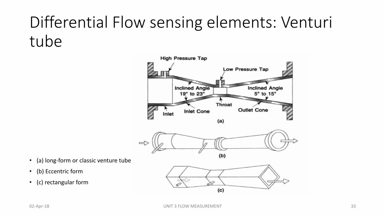
• (a) long-form or classic venture tube
• (b) Eccentric form
• (c) rectangular form
02-Apr-18 UNIT 3 FLOW MEASUREMENT 33
Differential Flow sensing elements: VenturitubeConstruction:
• A venturi tube is used where permanent pressure loss is of prime importance, and where maximum accuracy is desired in the measurement of high viscous fluids.
• It consists of • (i) a straight inlet section of the same diameter as the pipe in which the high pressure tap is
located, • (ii) a converging conical inlet section in which the cross-section of the stream decreases and
the velocity head and decrease of pressure head,• (iii) a cylindrical throat which provides for the low pressure tap location of the decreased
pressure in an area where flow velocity is neither increasing nor decreasing, and • (iv) a diverging recovery cone in which velocity decreases and the decreased velocity head is
recovered as pressure head, as shown in Figure 1.
• The pressure taps are located one-quarter to one-half pipe diameter up-stream of the inlet cone and at the middle of the throat section.
02-Apr-18 UNIT 3 FLOW MEASUREMENT 34
Differential Flow sensing elements: VenturitubeWorking:
• The function of the different size cones is to produce differential pressure inside the tube, which can be connected to the secondary pressure-measuring device.
• This will measure the differential pressure produced by the tube. This pressure difference can be calibrated in terms of flow rate.
• The venturi tube can be used to handle a fluid, which is handled by an orifice plate, and fluids that contains some solids, because these venturitubes contain no sharp corners and do not project into the fluid stream.
• It can be also used to handle slurries and dirty liquids that build up around other primary elements, if the pressure taps are protected from plugging.
02-Apr-18 UNIT 3 FLOW MEASUREMENT 35
Differential Flow sensing elements: VenturitubeWorking:
• The venturi tubes are usually made of cast iron or steel, and are built in several forms such as • (i) long-form or classic venturi tube.
• (ii) short-form where the outlet cone is shortened,
• (iii) an eccentric form to minimize the built up of heavy material and a
• (iv) rectangular form used in air duct-work.
02-Apr-18 UNIT 3 FLOW MEASUREMENT 36
Differential Flow sensing elements: Venturitube• Advantages:
• Less chances of getting clogged with sediments.• co-efficient of discharge is high.• Its behavior can be predicted perfectly.• Can be installed vertically, horizontally and inclined.• They are more accurate and can be used for a wide range of flows.• Around 90% of pressure drop can be recovered.
• Disadvantages:• They are large in size and hence where space is limited, they cannot be used.• Higher initial cost, installation and maintenance.• Require long laying length.• Cannot be used in pipes below 7.5 cm diameter.• Maintenance is not easy.• Cannot be altered for measuring pressure beyond a maximum velocity.
02-Apr-18 UNIT 3 FLOW MEASUREMENT 37
Differential Flow sensing elements: Pitot tube
02-Apr-18 UNIT 3 FLOW MEASUREMENT 38
Differential Flow sensing elements: Pitot tube
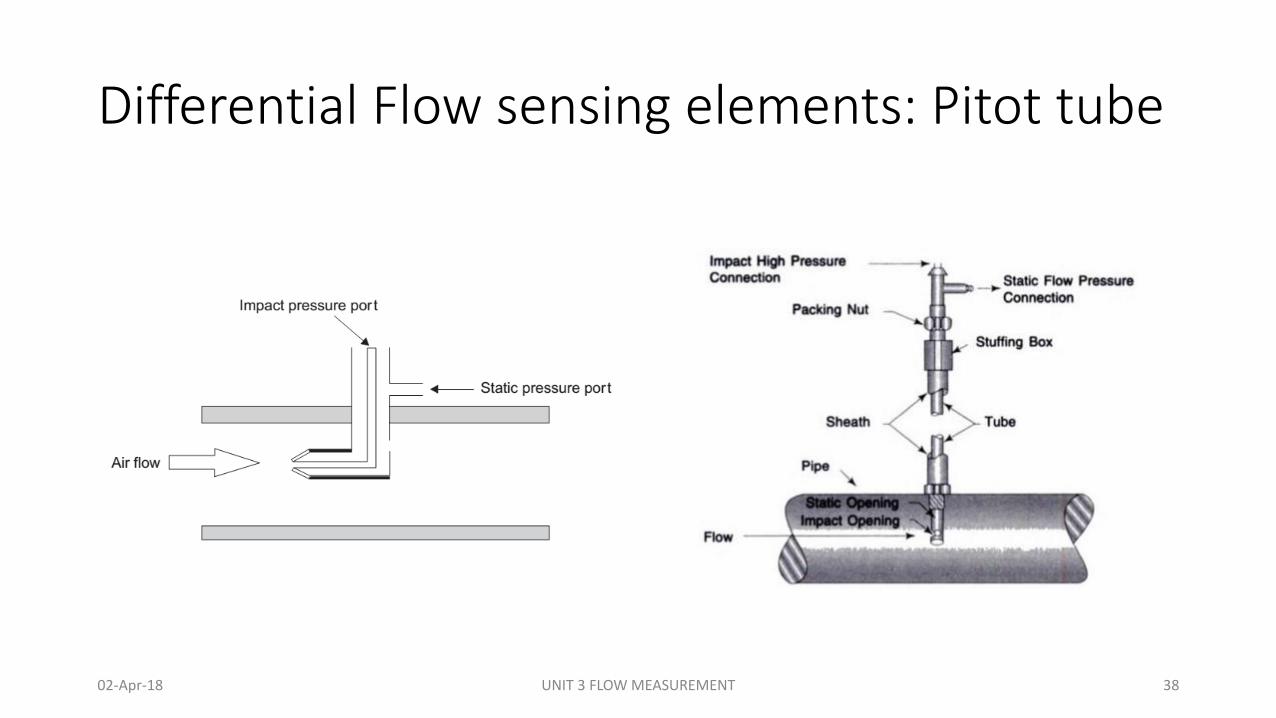
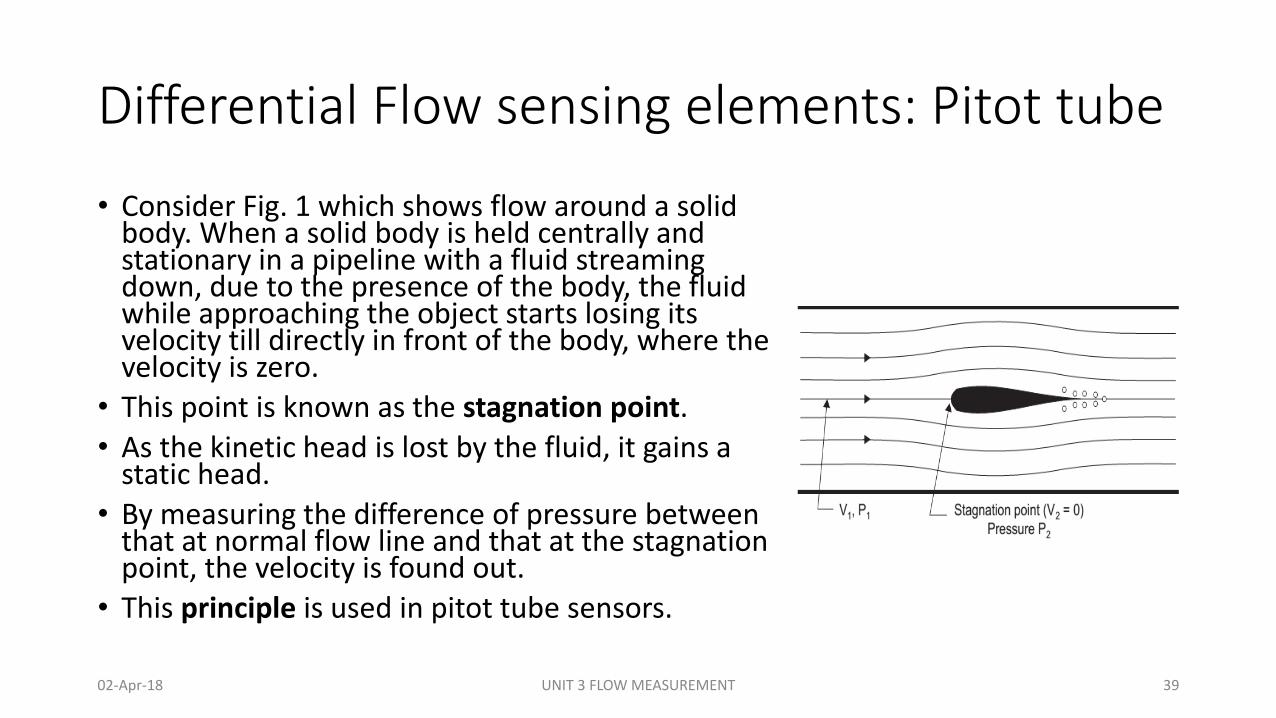
• Consider Fig. 1 which shows flow around a solid body. When a solid body is held centrally and stationary in a pipeline with a fluid streaming down, due to the presence of the body, the fluid while approaching the object starts losing its velocity till directly in front of the body, where the velocity is zero.
• This point is known as the stagnation point.
• As the kinetic head is lost by the fluid, it gains a static head.
• By measuring the difference of pressure between that at normal flow line and that at the stagnation point, the velocity is found out.
• This principle is used in pitot tube sensors.
02-Apr-18 UNIT 3 FLOW MEASUREMENT 39
Differential Flow sensing elements: Pitot tube
Construction:
• The simplest Pitot tube consists of a tube with an impact opening of 3.125 mm to 6.35 mm diameter pointing towards the approaching fluid.
• This measures the stagnation pressure. An ordinary upstream tap can be used for measuring the line pressure.
• A common industrial type of pitot tube consists of a cylindrical probe inserted into the air stream, as shown in Fig. 2.
• Fluid flow velocity at the upstream face of the probe is reduced substantially to zero.
• Velocity head is converted to impact pressure, which is sensed through a small hole in the upstream face of the probe.
02-Apr-18 UNIT 3 FLOW MEASUREMENT 40
Differential Flow sensing elements: Pitot tube
Working:• A corresponding small hole in the side of the probe senses static pressure. • A pressure instrument measures the differential pressure, which is
proportional to the square of the stream velocity in the vicinity of the impact pressure sensing hole.
• The total pressure developed at the point where the flow is stagnated is assumed to occur at the tip of a pitot tube or at a specific point on a bluff body immersed in the stream.
• The pitot tube causes practically no pressure loss in the flow stream. It is normally installed through a nipple in the side of the pipe.
• It is frequently installed through an isolation valve, so that it can be moved back and forth across the stream to establish the profile of flow velocity.
02-Apr-18 UNIT 3 FLOW MEASUREMENT 41
Differential Flow sensing elements: Pitot tube
• Advantages:• No pressure loss.• It is relatively simple.• It is readily adapted for flow measurements made in very large pipes or ducts.
• Disadvantages:• Poor accuracy.• Not suitable for dirty or sticky fluids and fluids containing solid particles.• Sensitive to upstream disturbances.
• Applications• Pitot tube is employed in a variety of flow measurement applications like air speed in racing
cars and Air Force fighter jets. In industries, pitot tubes are invariably put into use for measurement of
• Air flow in pipes, ducts, and stacks, and• Liquid flow in pipes, weirs, and open channels
02-Apr-18 UNIT 3 FLOW MEASUREMENT 42

Differential Flow sensing elements: Target flow meter
02-Apr-18 UNIT 3 FLOW MEASUREMENT 43
Differential Flow sensing elements: Target flow meterConstruction:
• The target meter measures flow by measuring the force on a target (or disc), centered in the pipe at right angles to the direction of fluid flow.
• The fluid flow develops a force on the target which is proportional to the square of the flow.
• A target meter consists of a target (or disc) which is mounted on a force bar (or beam) passing through a flexible seal, and is positioned in the centre of and perpendicular to the flowing stream.
• The device may be installed directly in the flow line, thus eliminating the need for pressure-tap connections.
02-Apr-18 UNIT 3 FLOW MEASUREMENT 44
Differential Flow sensing elements: Target flow meterWorking:• The flowing fluid while passing through the pipe, develops a force on the
target which is proportional to velocity head (the square of the flow). • The force bar transmits this force to a force transducer (either electronic or
pneumatic) to measure the force which is proportional to the square of the flow.
• The relationship between the flow rate and force is expressed by the equation
𝑄 = 𝐾 𝐹• Where Q= flow rate, K= a known coefficient, F= force
• The target meters are available in sizes from 12.5 to 203 mm pipe diameter, and an accuracy of about ±1/2% with proper calibration. The targets (or discs) are available with diameters of 0.6 to 0.8 times pipe diameter.
02-Apr-18 UNIT 3 FLOW MEASUREMENT 45
Differential Flow sensing elements: Target flow meterWorking:
• Another variation of target meter is also available which is known as drag body flow meter, as shown in Fig. 8.15. It also uses the same operating principle where the force is given by the equation,
𝐹 = 𝐶𝑑𝐴 𝜌 (𝑉2/2𝑔)
• where, F=force, Cd= drag coefficient, A= sensor area, ρ = fluid density, V2/2g= velocity head
• This force is detected and transmitted by a strain gauge bridge circuitry, into a voltage signal which is proportional to the square of the flow rate.
• The accuracy of this device ranges from ±1/2 to ±3% depending on the calibration used.
02-Apr-18 UNIT 3 FLOW MEASUREMENT 46
Differential Flow sensing elements: Target flow meter• Advantages:
• They are useful for difficult measurements such as slurries, polymer bearing and sediment-bearing materials corrosive mixtures, etc.
• They provide good accuracy when calibrated for specific streams.• Their repeatability is good.• They are good for relatively high temperatures and pressures.
• Disadvantages:• In-line mounting required in these flowmeters.• They have a limited calibration data.• In case of target flowmeters no-flow conditions must exist for zeroing
• Applications:• Target meters are applied in a number of fields for measurement of liquids, vapours and gases.
They are especially useful for measuring heavy viscous, dirty or corrosive fluids. The force-balance type (i.e. target type) can handle pressures upto 1,500 psig and temperatures to 398 °C, and the strain gauge type (i.e. drag body type) can handle pressures upto 5000 psig and temperature to 315 °C.
02-Apr-18 UNIT 3 FLOW MEASUREMENT 47
Variable area meter: Rotameter
02-Apr-18 UNIT 3 FLOW MEASUREMENT 48
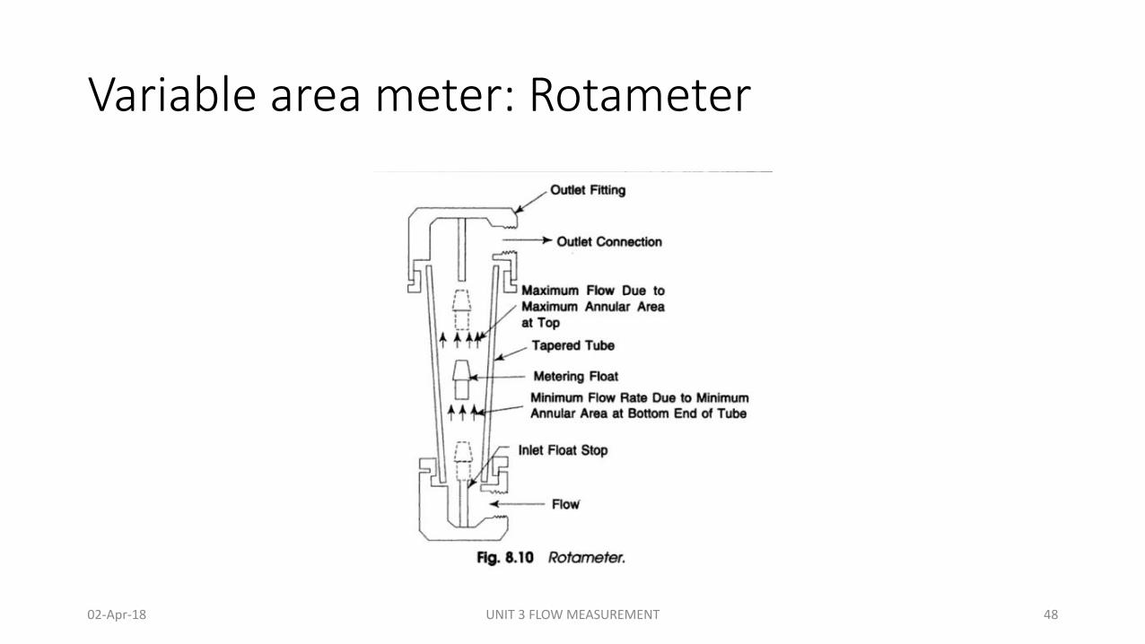
Variable area meter: Rotameter
Principle:
• When fluid or gas flows through a taper tube containing a float, a pressure difference is created between upper and lower side of the float. The float moves upwards by a force obtained by multiplying the pressure differential by the maximum cross sectional area of the float.
• Due to taper tube, as the float moves upwards, the fluid passing area increases because of which the differential pressure decreases. Upward movement of float stops when the differential pressure dynamically balances the dead load.
• Tapering of metering tube is so designed that the vertical movement of the float becomes linearly proportional to the rate of flow and the scale is provided to read the position of the float, thus it gives flow rate indication.
• Based on Bernoulli's theorem, the principle mentioned above can be theoretically expressed as follows.𝑄 = 𝑘𝐴 gh
• Where: Q = volumetric flow rate, e.g., gallons per minute• k = a constant• A = annular area between the float and the tube wall• g = force of gravity• h = pressure drop (head) across the float
02-Apr-18 UNIT 3 FLOW MEASUREMENT 49
Variable area meter: Rotameter
Construction:
• A rotameter consists of a tapered tube, typically made of glass with a 'float'.
• Float is made of anodized aluminum or a ceramic and it moves freely inside the glass tube.
• Floats will be pushed up by the drag force of the flow and pulled down by gravity.
• The drag force for a given fluid and float cross section is a function of flow speed squared only.
• A higher volumetric flow rate through a given area increases flow speed and drag force, so the float will be pushed upwards.
• However, as the inside of the rotameter is cone shaped (widens), the area around the float through which the medium flows increases, the flow speed and drag force decrease until there is mechanical equilibrium with the float's weight.
02-Apr-18 UNIT 3 FLOW MEASUREMENT 50
Variable area meter: Rotameter
Working:
• The position of float inside the glass tube is measured using appropriate scale or tube itself have scale printed on it. This height of the float can be calibrated in terms of the flow rate.
• Floats are made in many different shapes, with spheres and ellipsoids being the most common.
• The float may be diagonally grooved and partially colored so that it rotates axially as the fluid passes. This shows if the float is stuck since it will only rotate if it is free.
• Readings are usually taken at the top of the widest part of the float; the center for an ellipsoid, or the top for a cylinder. Some manufacturers use a different standard.
• The "float" must not float in the fluid: it has to have a higher density than the fluid, otherwise it will float to the top even if there is no flow.
• The mechanical nature of the measuring principle provides a flow measurement device that does not require any electrical power.
• If the tube is made of metal, the float position is transferred to an external indicator via a magnetic coupling. This capability has considerably expanded the range of applications for the variable area flowmeter, since the measurement can observed remotely from the process or used for automatic control.
02-Apr-18 UNIT 3 FLOW MEASUREMENT 51
Variable area meter: Rotameter
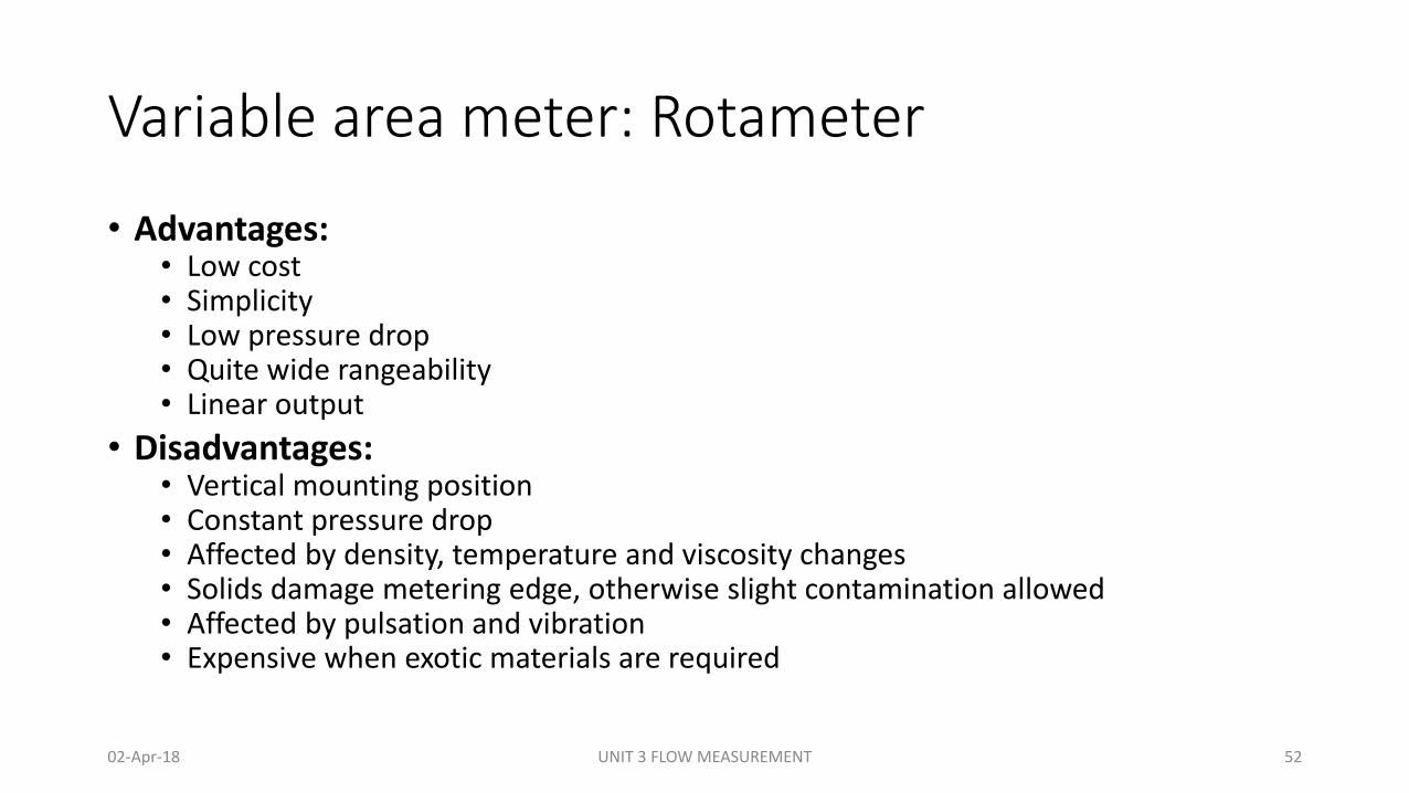
• Advantages:• Low cost• Simplicity• Low pressure drop• Quite wide rangeability• Linear output
• Disadvantages:• Vertical mounting position• Constant pressure drop• Affected by density, temperature and viscosity changes• Solids damage metering edge, otherwise slight contamination allowed• Affected by pulsation and vibration• Expensive when exotic materials are required
02-Apr-18 UNIT 3 FLOW MEASUREMENT 52
Magnetic flow meters
02-Apr-18 UNIT 3 FLOW MEASUREMENT 53

Magnetic flow meters
Principle:
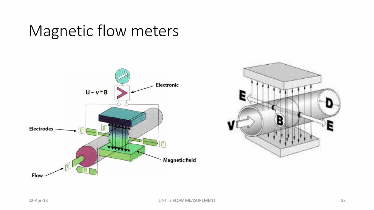
• The operation of a magnetic flowmeter or mag meter is based upon Faraday's Law, which states that the voltage induced across any conductor as it moves at right angles through a magnetic field is proportional to the velocity of that conductor.
• Faraday's Formula
E =C x V x B x L
where: E = The voltage generated in a conductor, C= Constant,
V = The velocity of the conductor, B = The magnetic field strength
L = The length of the conductor
• To apply this principle to flow measurement with a magnetic flowmeter, it is necessary first to state that the fluid being measured must be electrically conductive.
• As applied to the design of magnetic flowmeters, Faraday's Law indicates that signal voltage (E) is dependent on the average liquid velocity (V) the magnetic field strength (B) and the length of the conductor (L) (which in this instance is the distance between the electrodes).
02-Apr-18 UNIT 3 FLOW MEASUREMENT 54
Magnetic flow meters
Construction:
• The magnetic flowmeter consists of an electrically insulated or non conducting pipe such as fiber glass.
• A pair of electrodes mounted opposite to each other and flush with the inside walls of its pipe
• Magnetic coil mounted around the pipe so that a magnetic field is generated in a plane mutually perpendicular to the axis of the flowmeter body and to the plane of electrodes.
• If a metal pipe is used, an electrically insulating liner is provided to the inside of the pipe. A cut way view of the magnetic flow meter is shown in Fig. 1.
• Flowing liquid acts as the conductor, the length L is the distance between the electrodes and equals to the pipe diameter.
• The magnetic coils may energized either by AC or DC voltage, but the recent development is the pulse DC-type in which the magnetic coils are periodically energized.
02-Apr-18 UNIT 3 FLOW MEASUREMENT 55
Magnetic flow meters
Working:• As conductive fluid passes through the electrodes and magnetic field,
voltage is generated at tip of electrodes.• Magnetic meters are available in sizes from 2.54 to 2540 mm in diameter,
with an accuracy range ±1/2 to ±2%. The rangeability of such meters may be 30:1, however, normally accepted range is about 20:1. The measurement of these meters are independent of viscosity, density, temperature and pressure.
• In a new design of magnetic flowmeter, it can be inserted into the line through couplings. It consists of electrodes mounted on each side of the probe and magnetic coils which are also integral to the probe. The probe can be mounted on pipes of any size, and can easily be mounted for open channel flow.
02-Apr-18 UNIT 3 FLOW MEASUREMENT 56
Magnetic flow meters
• Advantages:
• They consist of no moving parts; hence there are no restrictions to the flow.
• They are competent enough to measure intricate and corrosive liquids and slurries.
• Moreover, they are capable of measuring forward as well as reverse flow with the same accuracy.
• Initial designs of electromagnetic flowmeters involved high power consumption and zero meter settings (i.e. no flow to initially set the meter to zero). However, advanced designs have eradicated all these problems. New Pulse-type excitation techniques have reduced power consumption to a great extent. Zero meter settings are also no longer mandatory
• Disadvantages:
• It is relatively expensive.
• It works only with fluids which are adequate electrical conductors.
• It is relatively heavy, especially in larger sizes.
• It must be full at all times.
• It must be explosion proof when installed in hazardous electrical areas.
02-Apr-18 UNIT 3 FLOW MEASUREMENT 57
Ultrasonic flow meters
02-Apr-18 UNIT 3 FLOW MEASUREMENT 58
Ultrasonic flow meters
• The term ‘ultrasonic’ refers to the signals (usually are short bursts of sine waves) whose frequency is above the range audible to human hearing which is 20 to 20000 Hz.
Principle
• The ultrasonic flow meter operates on the principle that the velocity of sound in a fluid in motion is the resultant of the velocity of sound in the fluid at rest plus or minus the velocity of the fluid itself.
• Types of Ultrasonic Flow Meters• Transit time flow meters
• Doppler Flow meter.
02-Apr-18 UNIT 3 FLOW MEASUREMENT 59
Ultrasonic flow meters
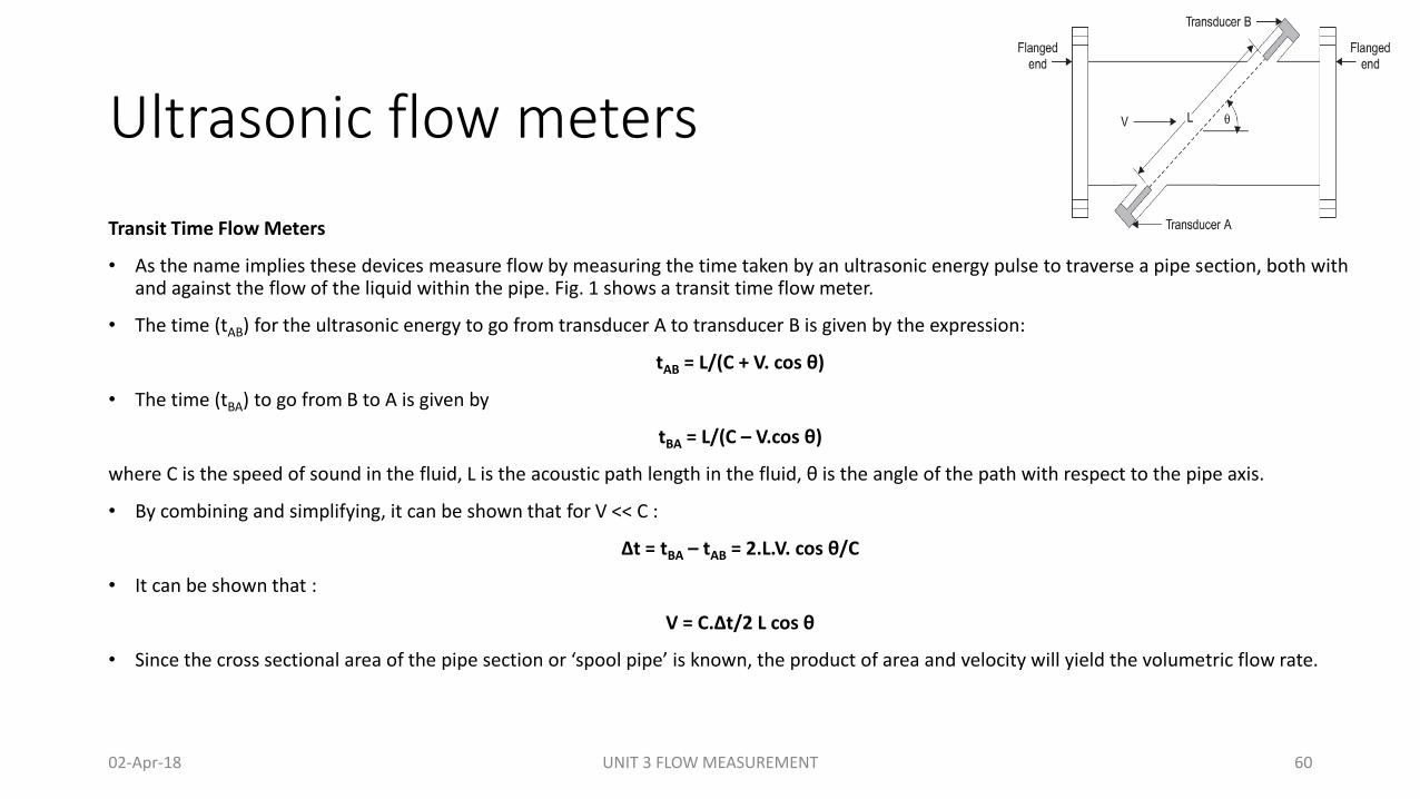
Transit Time Flow Meters
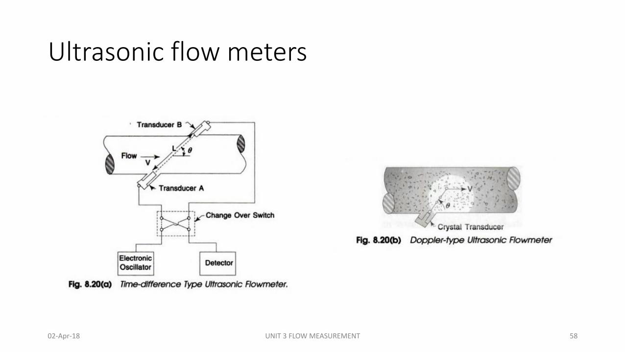
• As the name implies these devices measure flow by measuring the time taken by an ultrasonic energy pulse to traverse a pipe section, both with and against the flow of the liquid within the pipe. Fig. 1 shows a transit time flow meter.
• The time (tAB) for the ultrasonic energy to go from transducer A to transducer B is given by the expression:
tAB = L/(C + V. cos θ)
• The time (tBA) to go from B to A is given by
tBA = L/(C – V.cos θ)
where C is the speed of sound in the fluid, L is the acoustic path length in the fluid, θ is the angle of the path with respect to the pipe axis.
• By combining and simplifying, it can be shown that for V << C :
∆t = tBA – tAB = 2.L.V. cos θ/C
• It can be shown that :
V = C.∆t/2 L cos θ
• Since the cross sectional area of the pipe section or ‘spool pipe’ is known, the product of area and velocity will yield the volumetric flow rate.
02-Apr-18 UNIT 3 FLOW MEASUREMENT 60
Ultrasonic flow meters
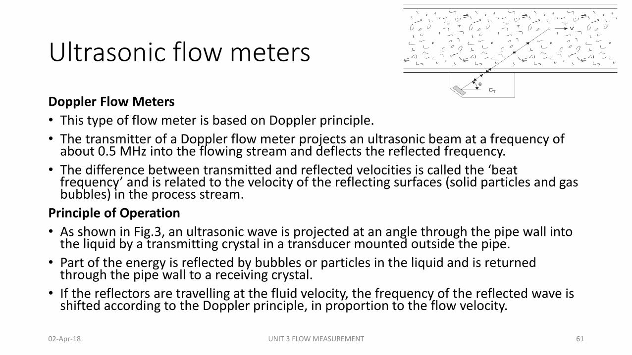
Doppler Flow Meters
• This type of flow meter is based on Doppler principle.
• The transmitter of a Doppler flow meter projects an ultrasonic beam at a frequency of about 0.5 MHz into the flowing stream and deflects the reflected frequency.
• The difference between transmitted and reflected velocities is called the ‘beat frequency’ and is related to the velocity of the reflecting surfaces (solid particles and gas bubbles) in the process stream.
Principle of Operation
• As shown in Fig.3, an ultrasonic wave is projected at an angle through the pipe wall into the liquid by a transmitting crystal in a transducer mounted outside the pipe.
• Part of the energy is reflected by bubbles or particles in the liquid and is returned through the pipe wall to a receiving crystal.
• If the reflectors are travelling at the fluid velocity, the frequency of the reflected wave is shifted according to the Doppler principle, in proportion to the flow velocity.
02-Apr-18 UNIT 3 FLOW MEASUREMENT 61
Ultrasonic flow meters
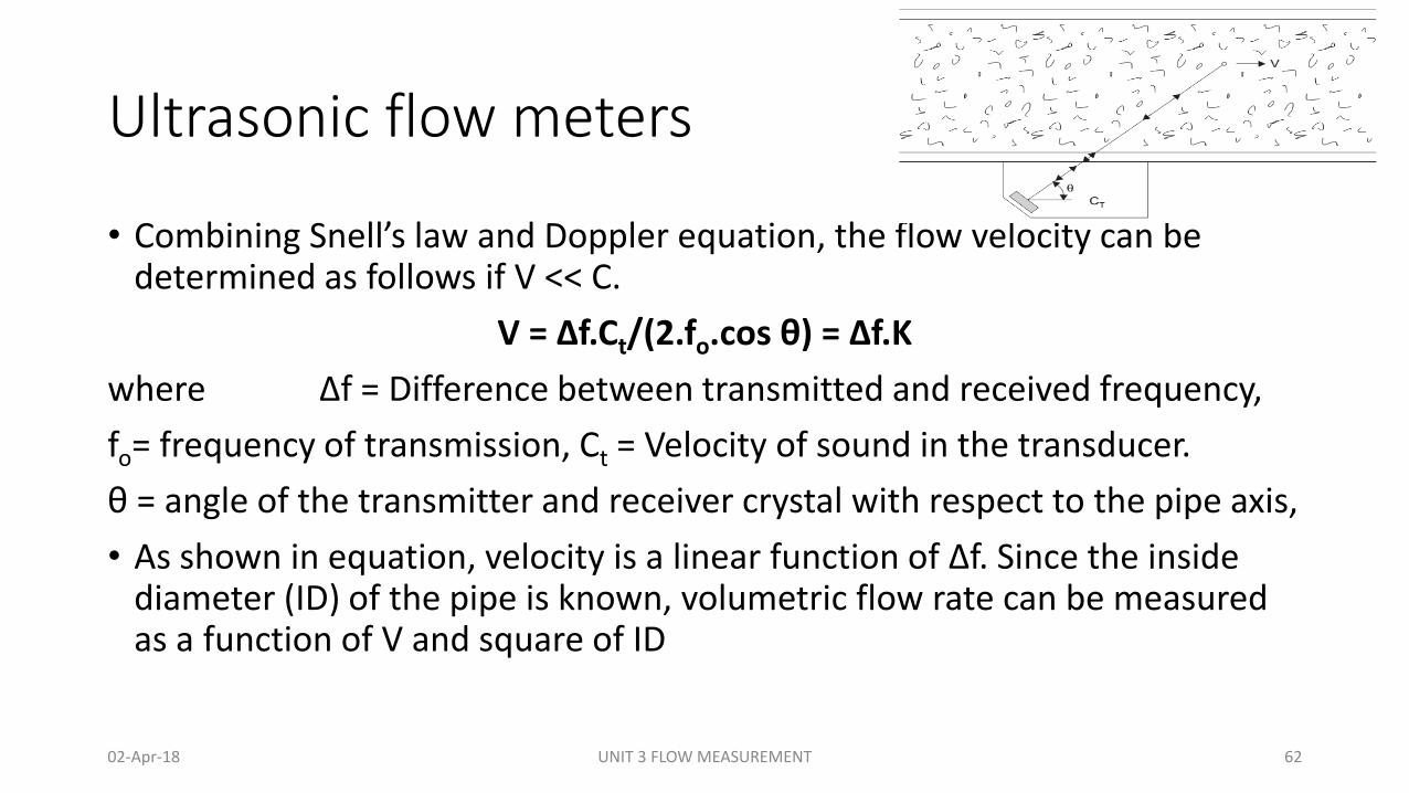
• Combining Snell’s law and Doppler equation, the flow velocity can be determined as follows if V << C.
V = ∆f.Ct/(2.fo.cos θ) = ∆f.K
where ∆f = Difference between transmitted and received frequency,
fo= frequency of transmission, Ct = Velocity of sound in the transducer.
θ = angle of the transmitter and receiver crystal with respect to the pipe axis,
• As shown in equation, velocity is a linear function of ∆f. Since the inside diameter (ID) of the pipe is known, volumetric flow rate can be measured as a function of V and square of ID
02-Apr-18 UNIT 3 FLOW MEASUREMENT 62

Ultrasonic flow meters
• Advantages:
• Ultrasonic meters are made up of no moving parts.
• They experience no pressure loss.
• They endow with maintenance-free operation. It is a key advantage as compared to conventional mechanical meters such as positive displacement meters, turbines etc.
• Furthermore, Ultrasonic flowmeters are consistently more accurate and reliable than a lot of other metering systems.
• With the emergence of 3-beam ultrasonic, all other flowmeters like mass, vortex, positive displacement and turbine flowmeters which are used to measure non-conductive fluids, have been successfully replaced by ultrasonic meters.
• Disadvantages:
• Still problematic for liquid and gas measurements
• Sound beam must traverse a representative cross section, therefore flow profile dependent. Long inlet and outlet sections required
• Errors due to deposits
• Transit time meters require clean liquids
• Doppler meters only for slight contamination or few gas bubbles
• Doppler meters affected by sound velocity changes due to temperature, density and concentration
• Unsuitable for heavily contaminated liquids
• Gas bubbles cause errors
02-Apr-18 UNIT 3 FLOW MEASUREMENT 63
Ultrasonic flow meters
Applications
• Ultrasonic flowmeters are perfect for wastewater applications or any other dirty liquid which is conductive or water based.
• Ultrasonic flowmeters normally does not work with distilled water or drinking water. Aerations would be needed in the clean liquid applications.
• Ultrasonic flowmeters are also best suited for applications where low pressure drop, chemical compatibility, and low maintenance are involved
02-Apr-18 UNIT 3 FLOW MEASUREMENT 64
Turbine flow meter.
02-Apr-18 UNIT 3 FLOW MEASUREMENT 65
Turbine flow meter.
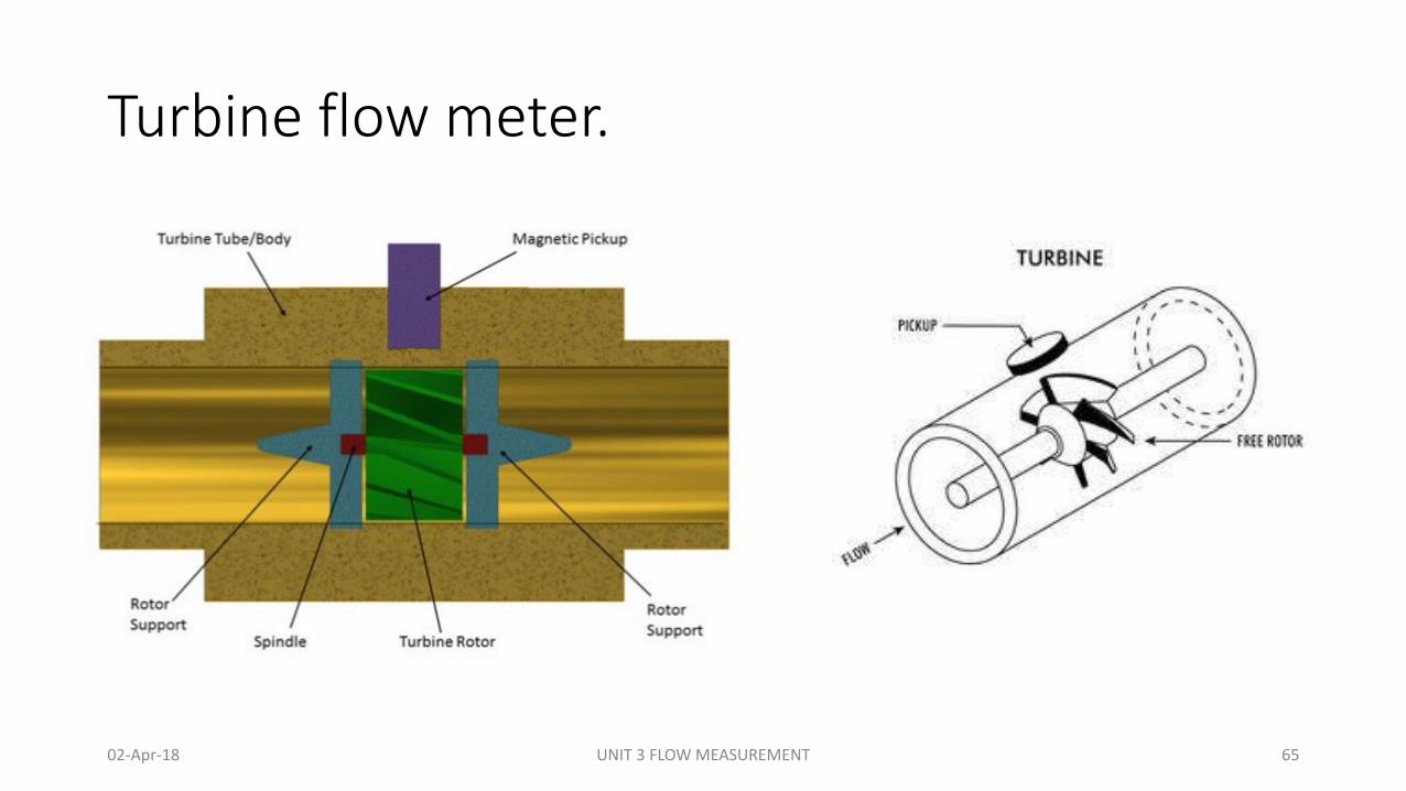
Principle:
• The turbine flowmeter is used for the measurement of liquid, gas and very low flow rates. It works on the basic principle of turbine.
Construction:
• It consists of a multi-bladed rotor (turbine wheel) which is mounted at right angles to the axis of the flowing liquid, as shown in Fig. 1.
• The rotor is supported by ball or sleeve bearings on a shaft which is retained in the flowmeter housing by a shaft-support section. The rotor is free to rotate about its axis.
02-Apr-18 UNIT 3 FLOW MEASUREMENT 66
Turbine flow meter.
• Working:• The flowing fluid impinges on the turbine blades (rotor), imparting a force
to the blade surface which causes the rotation of the rotor. • The speed of rotor is directly proportional to the fluid velocity, and hence
to volumetric flow rate when it is at a steady rotational speed. • The speed of rotation is monitored in most of the meters by a magnetic
pickup coil, which is fitted to the outside of the meter housing. • The magnetic-pickup coil consists of a permanent magnet with coil
windings which is mounted in close proximity to the rotor but internal to the fluid channel.
• As each rotor blade passes the magnetic-pickup coil, it generate a voltage pulse which is a measure of the flow rate, and the total number of pulses give a measure of the total flow.
02-Apr-18 UNIT 3 FLOW MEASUREMENT 67
Turbine flow meter.
• The electrical voltage pulses can be totalled; subtracted and manipulated by digital techniques so that a zero error characteristic of digital handling is provided from the pulse generator to the final read out.
• The K factor (i e, the number of pulses generated per gallon of flow) is given as
𝐾 =𝑇𝑘𝑓
𝑄
• where, K = pulses per volume unit, Tk =a time constant in min, Q =a volumetric flow rate in gpm and f= frequency in Hz
02-Apr-18 UNIT 3 FLOW MEASUREMENT 68
Turbine flow meter.
Advantages:
• No external power supply for Rotating vane and Woltman meters
• Turbine flowmeters suitable for cryogenic liquids
• Turbine flowmeters usable at extreme temperatures and pressures
Disadvantages:
• Limited choice of materials
• Only for low viscosities
• Moving parts, wear
• Sensitive to contamination
• Axial flow totalizers are flow profile sensitive
• Inlet and outlet sections required (not for rotating vane meters)
• Affected by overloading and quick changes at high differential pressure, danger of over speeding
• Vibration sensitive
02-Apr-18 UNIT 3 FLOW MEASUREMENT 69
Thermal flow meter (Mass Flow Meter)
02-Apr-18 UNIT 3 FLOW MEASUREMENT 70
Thermal flow meter (Mass Flow Meter)
Principle:
• It works on the principle of thermal conductivity.
Construction:
• Thermal flowmeters are very popular for the measurement of unsteady flow of gases, and can be used to measure flow rate in terms of mass, which is a very desirable feature, especially on gas service. There are two types of thermal flowmeters:
1. Heat Transfer Flowmeters
2. Hot-Wire Flow meters
02-Apr-18 UNIT 3 FLOW MEASUREMENT 71
Thermal flow meter (Mass Flow Meter)
Heat Transfer Flowmeters
• This type of flowmeter measures the rise in the temperature of the fluid after a known amount of heat has been added to it. Its theory is based upon the specific heat equation which is given as,
𝑄 = 𝑊𝐶𝑝 (𝑇2 − 𝑇1)
Where Q= heat transfer,
W= mass flow rate of fluid
Cp= Specific heat of the fluid
T1 = initial temperature of fluid after heat has been transferred
T2 = final temperature of fluid after heating the fluid.
02-Apr-18 UNIT 3 FLOW MEASUREMENT 72
Thermal flow meter (Mass Flow Meter)
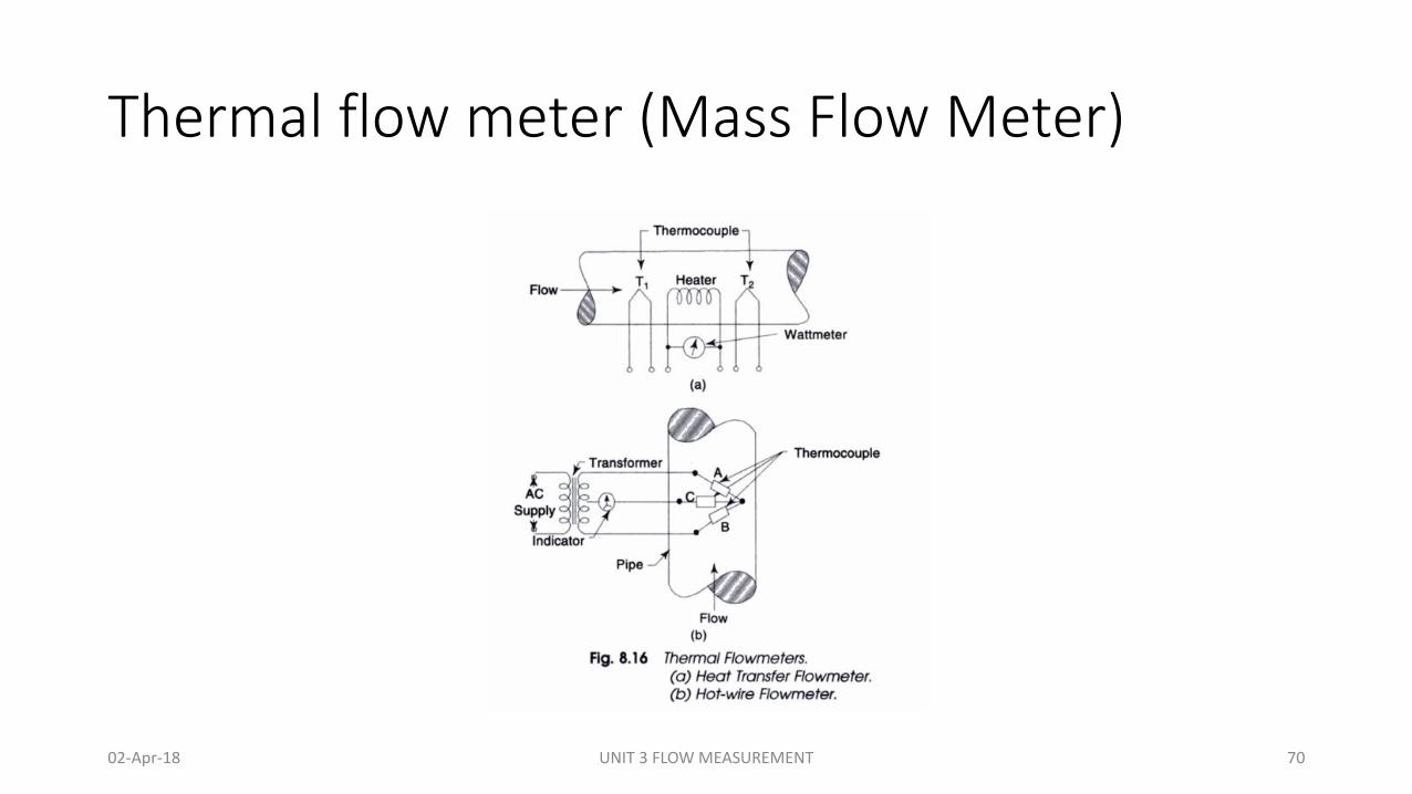
CONSTRUCTION AND WORKING
• A schematic diagram of a heat transfer flowmeter is shown in Fig. 8.16 (a), which consists of an electric immersion heater for the heating of flowing fluid.
• Two thermocouples (or resistance thermometers) TI and T2 are placed at each side of the heater as in Fig. 8.16(a).
• The thermocouple TI measures the temperature of fluid before it is heated, while the thermocouple T2 measures the temperature so after.
• The power supply to the heater equals the heat transferred to the fluid, i e. Q, and is measured by a wattmeter. Thus by measuring the values of Q, TI and T2 the flow rate W of liquid is determined from the above equation.
• This type of flowmeter has disadvantages in that the temperature sensor and the heater are directly placed into the fluid stream, and thus, they are easily damaged by corrosion and erosion.
• Furthermore, large input power is required to measure high flow rates. These disadvantages are overcome by mounting the heater, and upstream and downstream temperature sensors (TI and T2) on the outside of the piping. But it results in non-linear response.
02-Apr-18 UNIT 3 FLOW MEASUREMENT 73
Thermal flow meter (Mass Flow Meter)
Hot-Wire Flow meters
• This type of flowmeter measures the effect of the flowing fluid on a hot body.
• A hot-wire flowmeter consists of two thermocouples, A and B, connected in series to form a thermopile.
• A third thermocouple C is placed in the output circuit of the thermopile, as shown in Fig. 8.16(b). The thermopile is heated by passing an alternating current to it.
• The alternating current does not pass through the third thermocouple and it is therefore not electrically heated.
• The whole assembly is placed into the fluid (usually gas) stream whose flow rate is to be determined. The fluid (gas) cools the heated thermopile by convection, and since the input power to the thermopile is held constant, the thermopile attains an equilibrium temperature and produces an emf that is a function of the temperature of the gas, velocity of the gas, and its density, specific heat, and thermal conductivity.
• The third thermocouple (unheated) attains the ambient temperature of the gas, generating an emf that is proportional to the gas temperature and which cancels the effect of the ambient gas temperature on the output signal of the heated thermopile.
02-Apr-18 UNIT 3 FLOW MEASUREMENT 74
Thermal flow meter (Mass Flow Meter)
• The output voltage signal of this type of instrument is given by the equation.
• 𝐸 =𝐶
2 𝜋𝐾𝐶𝑝𝜌𝑑𝑉1/2
+𝐾
• Where E= voltage generated, C= instrument constant, K= thermal conductivity of fluid, Cp= specific heat of fluid, d= diameter of heated thermocouple wire, V=velocity of fluid and 𝜌 = density of the flowing fluid
• It can be designed to work with pressure upto 1200 psig (8.3 MPa).
02-Apr-18 UNIT 3 FLOW MEASUREMENT 75
Thermal flow meter (Mass Flow Meter)
• Advantages:
• Thermal flow meters have no moving parts, which reduces maintenance and permits the use in demanding application areas, including saturated gas.
• Gas mass meters calculate mass flow rather than volumetric flow and do not require temperature or pressure correction, which means there is no additional expense for the purchase and installation of additional equipment.
• Thermal flowmeters provide excellent accuracy and repeatability over a wide range of flow rates.
• Thermal mass flow meters can measure flow in large pipes.
• Disadvantages:
• Gas mass meter use is limited to clean, non abrasive fluids
• Presence of moisture or droplets can lead to measurement inaccuracy
• Thermal properties must be known: variation from calibrated values can cause inaccuracies
• Relatively high initial cost
02-Apr-18 UNIT 3 FLOW MEASUREMENT 76
Vortex flow meter
02-Apr-18 UNIT 3 FLOW MEASUREMENT 77
Vortex flow meter
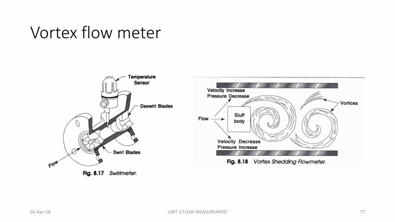
• Currently, there are three types of vortex flowmeters commercially available.
1. Swirlmeters
2. Vortex shedding meter
3. Fluidic meter
02-Apr-18 UNIT 3 FLOW MEASUREMENT 78
Vortex flow meter
Swirlmeters:
Principle:
• They operates on the principle of vortex precession
Construction:
• It is a digital volumetric device which has no moving parts. It gives an output in the form of pulses whose frequency is proportional to fluid flow rate.
• Figure 1 shows the construction of a swirlmeter. It consists of a fixed set of swirl blades, usually made of stainless steel, which introduce a spinning or swirling motion to the fluid at the inlet.
• At the downstream of the swirl blades, there is a venturi-like contraction and expansion of the flow passage.
• A temperature sensor (e.g. thermistor) is placed at the downstream to the blades which is heated by a constant electric current.
• At the exit of the meter, deswirl blades are fixed to straighten out the flow leaving the meter, as shown in figure. Its purpose is to isolate the meter from downstream piping effects.
02-Apr-18 UNIT 3 FLOW MEASUREMENT 79
Vortex flow meter
Working:
• As the fluid passes through the fixed set of swirl blades at the inlet, a swirling (or spinning) motion is imparted to it.
• In the area where expansion occurs, the swirling flow precedes or oscillates at a frequency proportional to the fluid.
• This procession of the fluid causes variations in temperature and resistance of the thermistor (sensor).
• The amount of heat extracted from the thermistor is dependent upon the fluid velocity.
• Consequently, each high velocity vortex passed the thermistor, changes the resistance and, since a constant current is applied, the resistance changes is converted into voltage pulses which are amplified, filtered and transformed into constant amplitude high level pulses of square waveform.
• The frequency of the pulses are measured by an electronic counter which gives the flow rate of fluid.
02-Apr-18 UNIT 3 FLOW MEASUREMENT 80
Vortex flow meter
Vorter Shedding Flowmeters:
Principle:
• The operation of the vortex shedding flowmeter is based on the phenomenon known as vortex shedding which occurs when a gas or liquid flows around a non-stream lined (or blunt) object known as sluff body.
02-Apr-18 UNIT 3 FLOW MEASUREMENT 81
Vortex flow meter
• Construction:
• When a fluid flows past an obstacle, boundary layers of slow moving fluid are formed along the outer surfaces of the obstacle and the flow is unable to follow contours of the obstacle on its downstream side.
• Thus the flow layers are separated from the surface of the object, and a low pressure area is formed behind the object which causes the separated layers to get detached from the main stream of the fluid and roll themselves into eddies or vortices in the low pressure area, as shown Fig. 11.18.
• Each eddy on vortex first grows and gets detached or shed from alternate sides of the object. The frequency at which the vortices are formed is directly proportional to the fluid velocity
02-Apr-18 UNIT 3 FLOW MEASUREMENT 82
Vortex flow meter
Working:
• As a vortex is shed from one side of the bluff body the fluid velocity on that side increases and the pressure decreases, and at the same time the velocity of the opposite side decreases and pressure increases, thus causing a net pressure change across the body.
• As the next vortex is shed from the opposite side of the bluff body, the entire effect is reversed. Therefore, the pressure of velocity and distribution in and around the bluff body changes at the same frequency as the vortex shedding frequency.
• A flow sensitive detector senses the changes in pressure of velocity, which can be either a heated thermistor or a spherical magnetic shuttle.
02-Apr-18 UNIT 3 FLOW MEASUREMENT 83
Vortex flow meter
Advantages:• No moving parts• Rugged construction• Suitable for liquids, gases and steam• Easily sterilized• Unaffected by pressure, temperature and density changes• Linear relationship between flow rate and measured valueDisadvantages:• Inlet and outlet sections required• Minimum Reynolds number required
02-Apr-18 UNIT 3 FLOW MEASUREMENT 84
Mass flow meter
• Mass meters measure the mass flow rate directly.
• Thermal Flowmeter
• The thermal mass flowmeter operates independent of density, pressure, and viscosity. Thermal meters use a heated sensing element isolated from the fluid flow path where the flow stream conducts heat from the sensing element. The conducted heat isdirectly proportional to the mass flow rate and the temperature difference is calculated to mass flow.
• The accuracy of the thermal mass flow device depends on the calibrations reliability of the actual process and variations in the temperature, pressure, flow rate, heat capacity and viscosity of the fluid.
• Coriolis Flowmeter
• Direct mass measurement sets Coriolis flowmeters apart from other technologies. Mass measurement is not sensitive to changes in pressure, temperature, viscosity and density. With the ability to measure liquids, slurries and gases, Coriolis flowmeters are universal meters.
• Coriolis Mass Flowmeter uses the Coriolis effect to measure the amount of mass moving through the element. The fluid to be measured runs through a U-shaped tube that is caused to vibrate in an angular harmonic oscillation. Due to the Coriolis forces, the tubes will deform and an additional vibration component will be added to the oscillation. This additional component causes a phase shift on some places of the tubes which can be measured with sensors.
• The Coriolis flow meters are in general very accurate, better than +/-0,1% with an turndown rate more than 100:1. The Coriolis meter can also be used to measure the fluids density.
02-Apr-18 UNIT 3 FLOW MEASUREMENT 85
Mass flow meter
Advantages of Mass Flow Measurement
• Thermal flow meters have no moving parts, which reduces maintenance and permits the use in demanding application areas, including saturated gas.
• Gas mass meters calculate mass flow rather than volumetric flow and do not require temperature or pressure correction, which means there is no additional expense for the purchase and installation of additional equipment.
• Thermal flowmeters provide excellent accuracy and repeatability over a wide range of flow rates.
• Thermal mass flow meters can measure flow in large pipes.
02-Apr-18 UNIT 3 FLOW MEASUREMENT 86
Positive displacement meters:
• Positive displacement type flow meters are generally used for accurate measurement of steady flow. These flow meters are working under the following principle.
Principle:• Positive displacement meters split the flow of liquids into separate
known volumes based on the physical dimensions of the meter, and count them or totalize them.
• They are mechanical meters in that one or more moving parts, located in the flow stream, physically separate the fluid into increments.
• The general accuracy of these meters is dependent upon minimizing clearances between the moving and stationary parts and maximizing the length of the flowing path. For this reason, accuracy tends to increase as size increases.
02-Apr-18 UNIT 3 FLOW MEASUREMENT 87
Positive displacement meters:
Reciprocating Piston Meter (Piston cylinder type)
• Construction and Working:
• The reciprocating piston meter is the oldest of the positive displacement meters. It is widely used in petroleum industry.
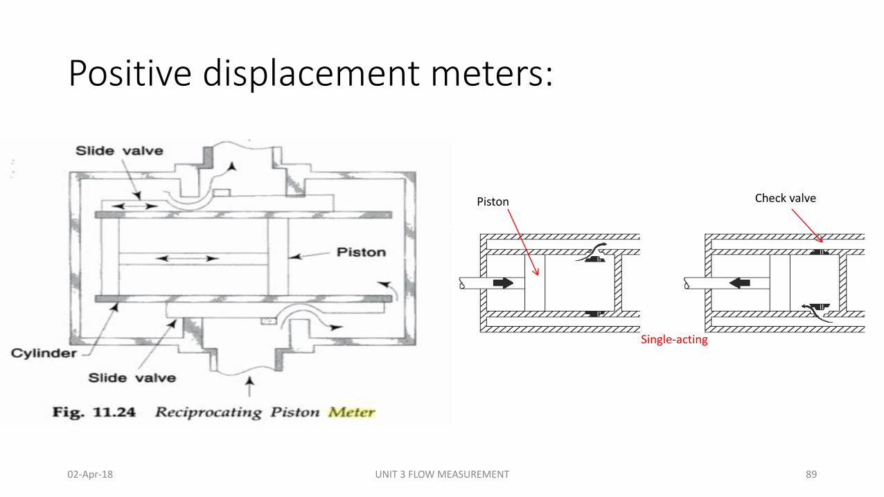
• It consists of a cast iron cylinder fitted with a piston, as shown in Fig. 11.24. Two slide valves are attached at the inlet and outlet ports.
• The fluid to be measured enters through the inlet forcing the piston to the left until the cylinder is full and piston is in its extreme left position.
• At this point, an external leakage causes both slide valves to move and thus the liquid enters the left cylinder forcing the piston to its extreme right position.
• When the cylinder becomes full, the slide valves again move and the cycle is repeated. The external arm of the slide valve drives a counter which provides a total of the fluid quantity that has passed through the meter.
• Instead of one piston, a number of pistons operating on a center crank are generally incorporated with this type of meter The accuracy of these meters are from +0.2 to +0.3%.
02-Apr-18 UNIT 3 FLOW MEASUREMENT 88
Positive displacement meters:
Single-acting
Piston Check valve
02-Apr-18 UNIT 3 FLOW MEASUREMENT 89
Piston pump:
Positive-Displacement Pumps:Reciprocating Pumps
02-Apr-18 UNIT 3 FLOW MEASUREMENT 90
Positive displacement meters:
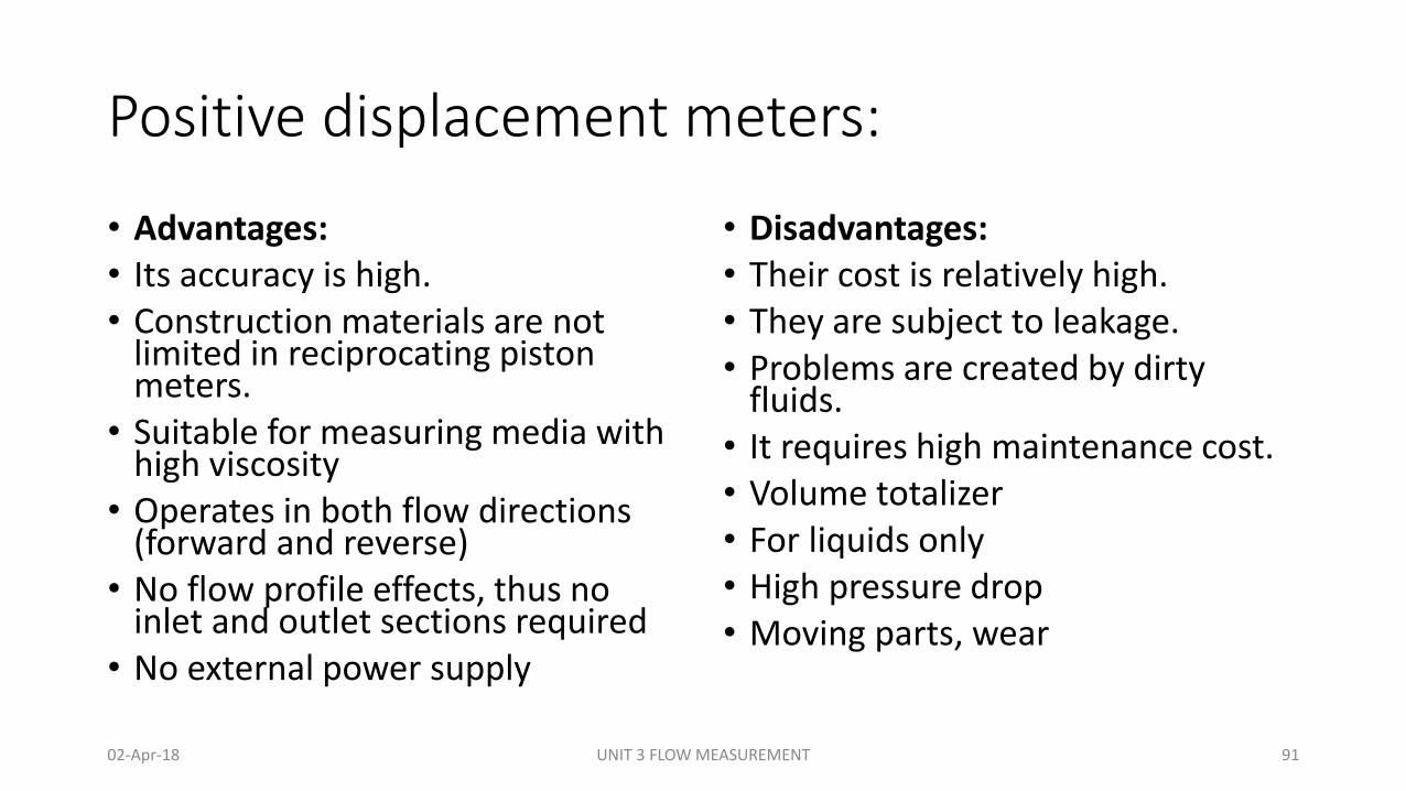
• Advantages:• Its accuracy is high.• Construction materials are not
limited in reciprocating piston meters.
• Suitable for measuring media with high viscosity
• Operates in both flow directions (forward and reverse)
• No flow profile effects, thus no inlet and outlet sections required
• No external power supply
• Disadvantages:• Their cost is relatively high.• They are subject to leakage.• Problems are created by dirty
fluids.• It requires high maintenance cost.• Volume totalizer• For liquids only• High pressure drop• Moving parts, wear
02-Apr-18 UNIT 3 FLOW MEASUREMENT 91
Positive displacement meters:
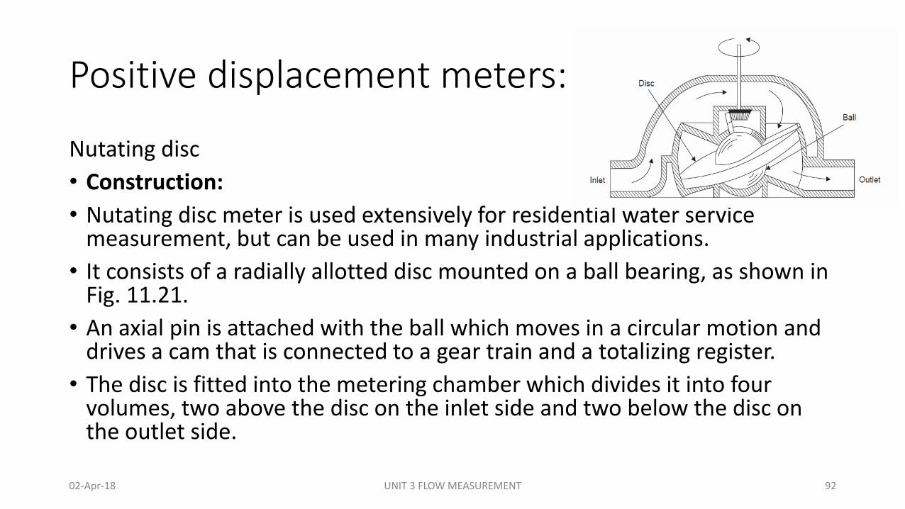
Nutating disc
• Construction:
• Nutating disc meter is used extensively for residential water service measurement, but can be used in many industrial applications.
• It consists of a radially allotted disc mounted on a ball bearing, as shown in Fig. 11.21.
• An axial pin is attached with the ball which moves in a circular motion and drives a cam that is connected to a gear train and a totalizing register.
• The disc is fitted into the metering chamber which divides it into four volumes, two above the disc on the inlet side and two below the disc on the outlet side.
02-Apr-18 UNIT 3 FLOW MEASUREMENT 92
Positive displacement meters:
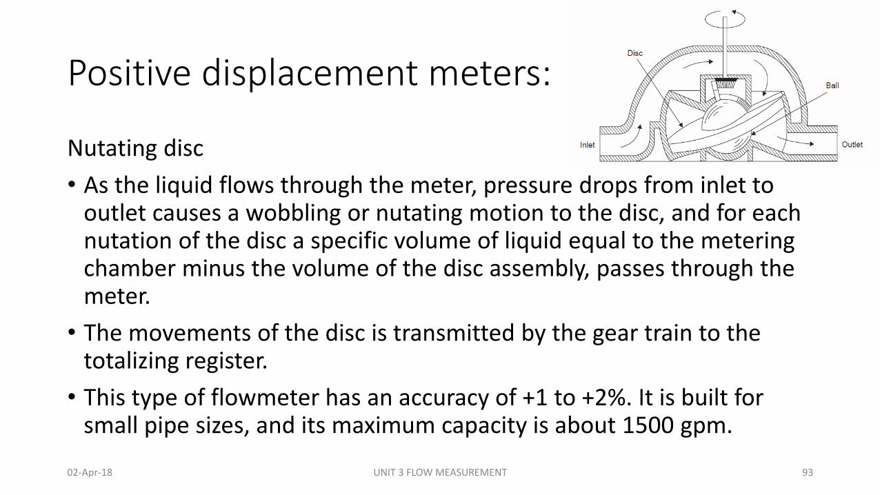
Nutating disc
• As the liquid flows through the meter, pressure drops from inlet to outlet causes a wobbling or nutating motion to the disc, and for each nutation of the disc a specific volume of liquid equal to the metering chamber minus the volume of the disc assembly, passes through the meter.
• The movements of the disc is transmitted by the gear train to the totalizing register.
• This type of flowmeter has an accuracy of +1 to +2%. It is built for small pipe sizes, and its maximum capacity is about 1500 gpm.
02-Apr-18 UNIT 3 FLOW MEASUREMENT 93
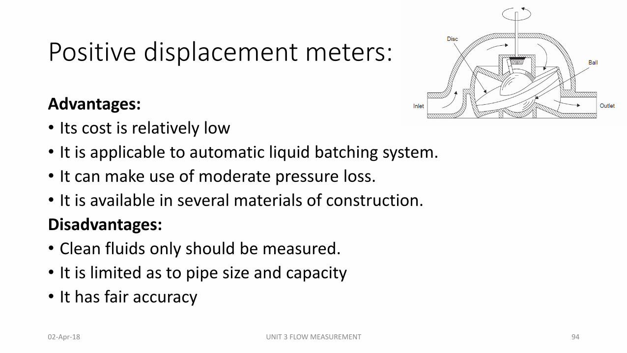
Positive displacement meters:
Advantages:
• Its cost is relatively low
• It is applicable to automatic liquid batching system.
• It can make use of moderate pressure loss.
• It is available in several materials of construction.
Disadvantages:
• Clean fluids only should be measured.
• It is limited as to pipe size and capacity
• It has fair accuracy
02-Apr-18 UNIT 3 FLOW MEASUREMENT 94
Positive displacement meters:
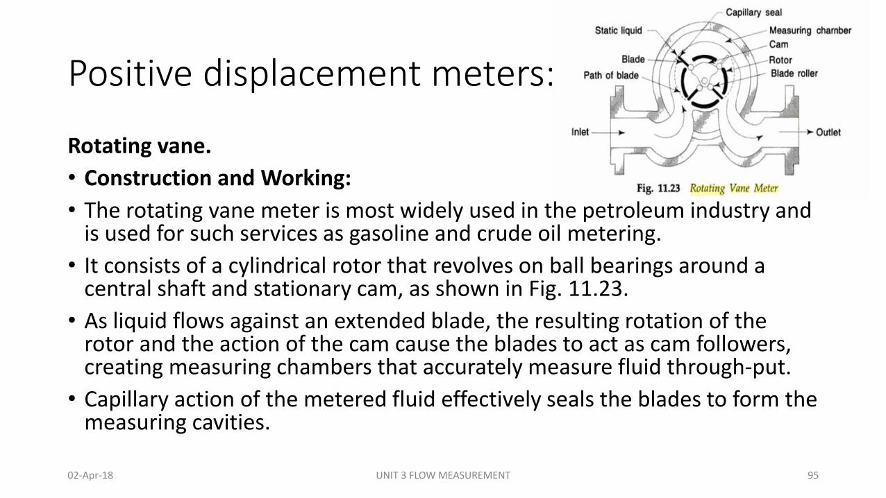
Rotating vane.
• Construction and Working:
• The rotating vane meter is most widely used in the petroleum industry and is used for such services as gasoline and crude oil metering.
• It consists of a cylindrical rotor that revolves on ball bearings around a central shaft and stationary cam, as shown in Fig. 11.23.
• As liquid flows against an extended blade, the resulting rotation of the rotor and the action of the cam cause the blades to act as cam followers, creating measuring chambers that accurately measure fluid through-put.
• Capillary action of the metered fluid effectively seals the blades to form the measuring cavities.
02-Apr-18 UNIT 3 FLOW MEASUREMENT 95
Positive displacement meters:
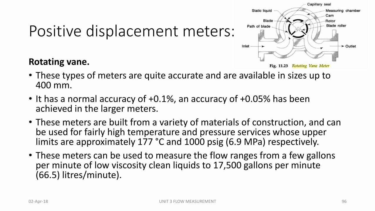
Rotating vane.
• These types of meters are quite accurate and are available in sizes up to 400 mm.
• It has a normal accuracy of +0.1%, an accuracy of +0.05% has been achieved in the larger meters.
• These meters are built from a variety of materials of construction, and can be used for fairly high temperature and pressure services whose upper limits are approximately 177 °C and 1000 psig (6.9 MPa) respectively.
• These meters can be used to measure the flow ranges from a few gallons per minute of low viscosity clean liquids to 17,500 gallons per minute (66.5) litres/minute).
02-Apr-18 UNIT 3 FLOW MEASUREMENT 96
Positive displacement meters:
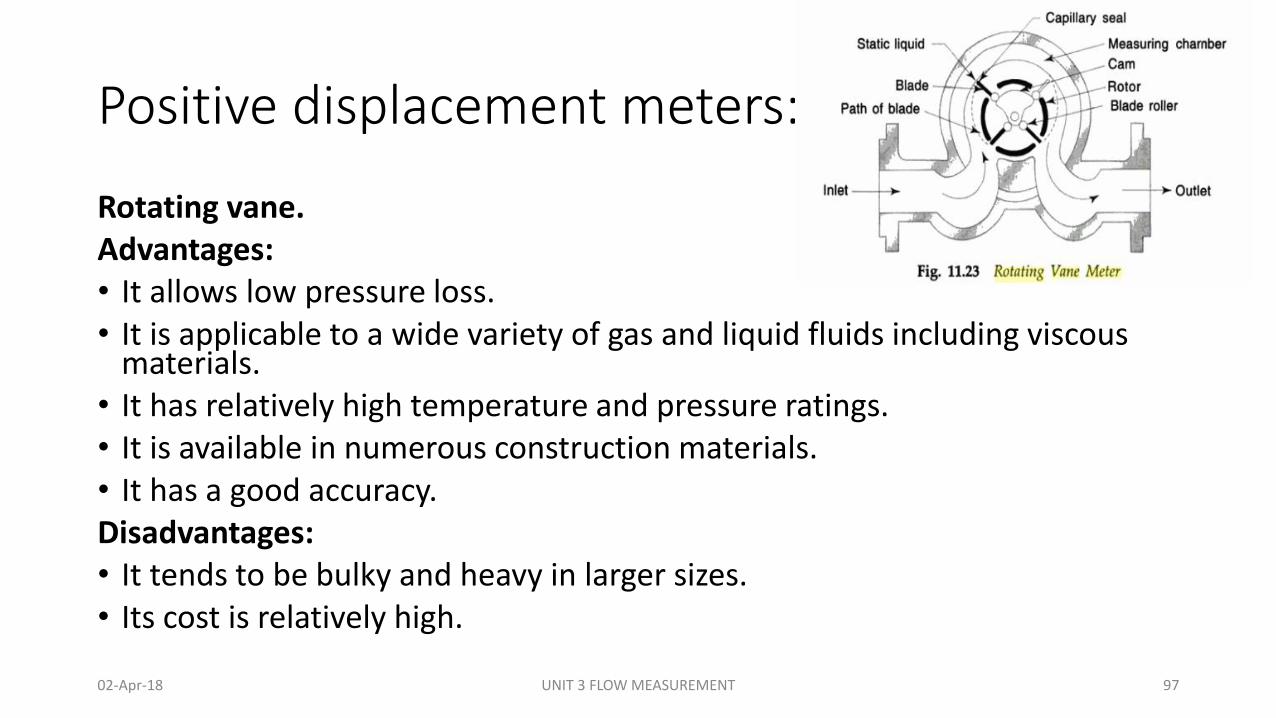
Rotating vane.Advantages:• It allows low pressure loss.• It is applicable to a wide variety of gas and liquid fluids including viscous
materials.• It has relatively high temperature and pressure ratings. • It is available in numerous construction materials. • It has a good accuracy.Disadvantages:• It tends to be bulky and heavy in larger sizes. • Its cost is relatively high.
02-Apr-18 UNIT 3 FLOW MEASUREMENT 97
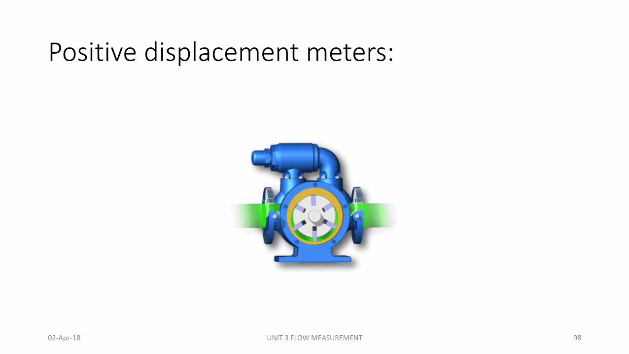
Positive displacement meters:
02-Apr-18 UNIT 3 FLOW MEASUREMENT 98
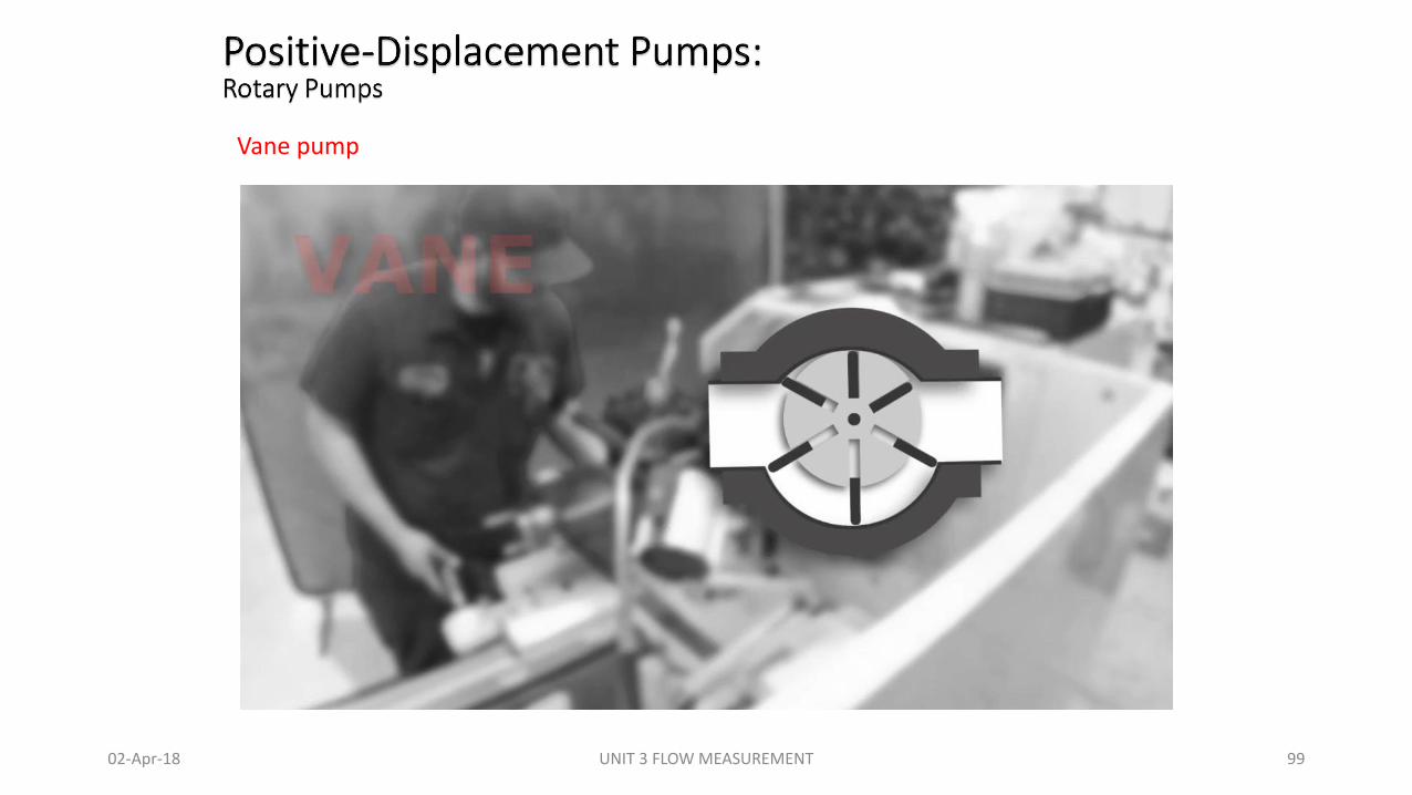
Vane pump
02-Apr-18 UNIT 3 FLOW MEASUREMENT 99
Positive-Displacement Pumps:Rotary Pumps: Vane gear
02-Apr-18 UNIT 3 FLOW MEASUREMENT 100
Positive-Displacement Pumps:Rotary Pumps: Vane gear
02-Apr-18 UNIT 3 FLOW MEASUREMENT 101
Flow Switch Types
• Flow switches are categorized either by the flowing media or by the measurement type. This means that the types can be combined, such as volumetric liquid flow switch.
• Gas flow switches are for media such as air and steam. They are commonly used in HVAC applications.
• Liquid flow switches are for media including water, lubricants, chemicals, and slurries. They are used in a wide variety of industry applications.
• Volumetric flow switches are used to measure the flow of liquids or gases. This measurement is done based on volume per unit time (i.e. cubic feet per minute).
• Velocity flow switches are used to measure the flow rate of moving media. This measurement is done in terms of velocity (i.e. feet per minute).
02-Apr-18 UNIT 3 FLOW MEASUREMENT 102

Flow switches
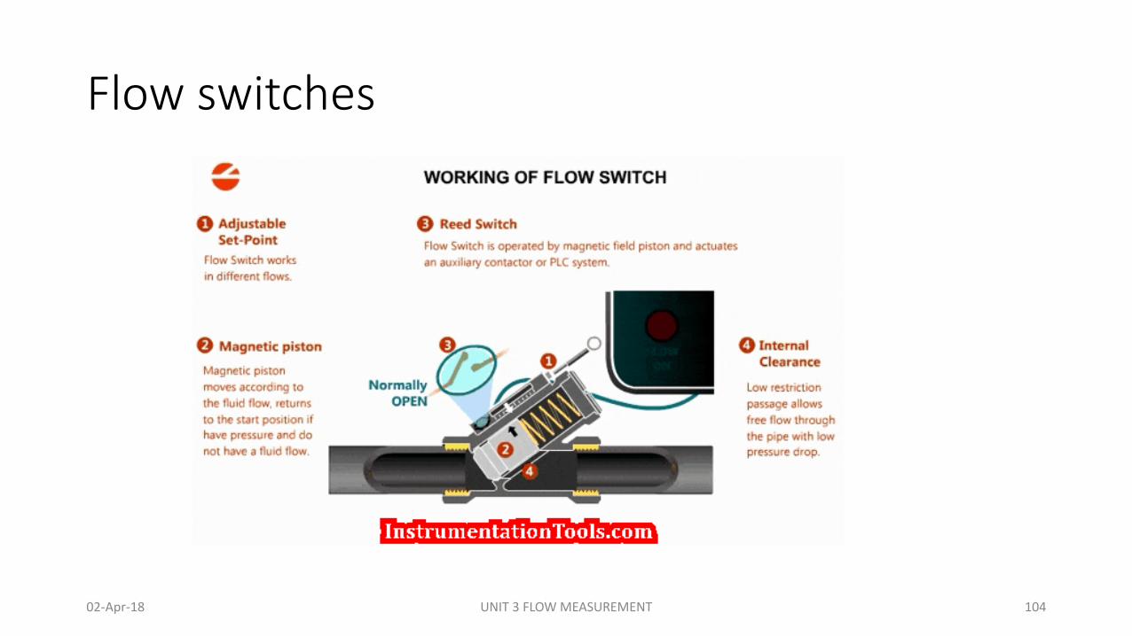
• Flow switches are used to determine if the flow rate is above or below a certain flow rate. This value (the set point) can be fixed or adjustable.
• When the set point is reached, the response can be the actuation of an electric circuit.
• When the flow switch is actuated, it will stay in that condition until the flow rate moves back from the set point by some amount.
• The operating principle is based on a free floating magnetic piston which responds only to the motion of fluids within the line, not to static or system pressures.
• In the presence of fluid flow, controlled movement of the piston actuates an external sealed reed switch.
• This switch can be used to actuate audible or visual alarms, as well as relays, or other controls. The piston’s movement by the fluid flow can be seen in the animation.
02-Apr-18 UNIT 3 FLOW MEASUREMENT 103
Flow switches
02-Apr-18 UNIT 3 FLOW MEASUREMENT 104
Flow transmitters (Pneumatic and Electronic).
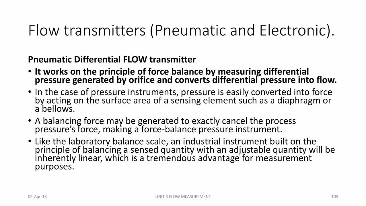
Pneumatic Differential FLOW transmitter• It works on the principle of force balance by measuring differential
pressure generated by orifice and converts differential pressure into flow.• In the case of pressure instruments, pressure is easily converted into force
by acting on the surface area of a sensing element such as a diaphragm or a bellows.
• A balancing force may be generated to exactly cancel the process pressure’s force, making a force-balance pressure instrument.
• Like the laboratory balance scale, an industrial instrument built on the principle of balancing a sensed quantity with an adjustable quantity will be inherently linear, which is a tremendous advantage for measurement purposes.
02-Apr-18 UNIT 3 FLOW MEASUREMENT 105
Flow transmitters
02-Apr-18 UNIT 3 FLOW MEASUREMENT 106
Flow transmitters (Pneumatic and Electronic).
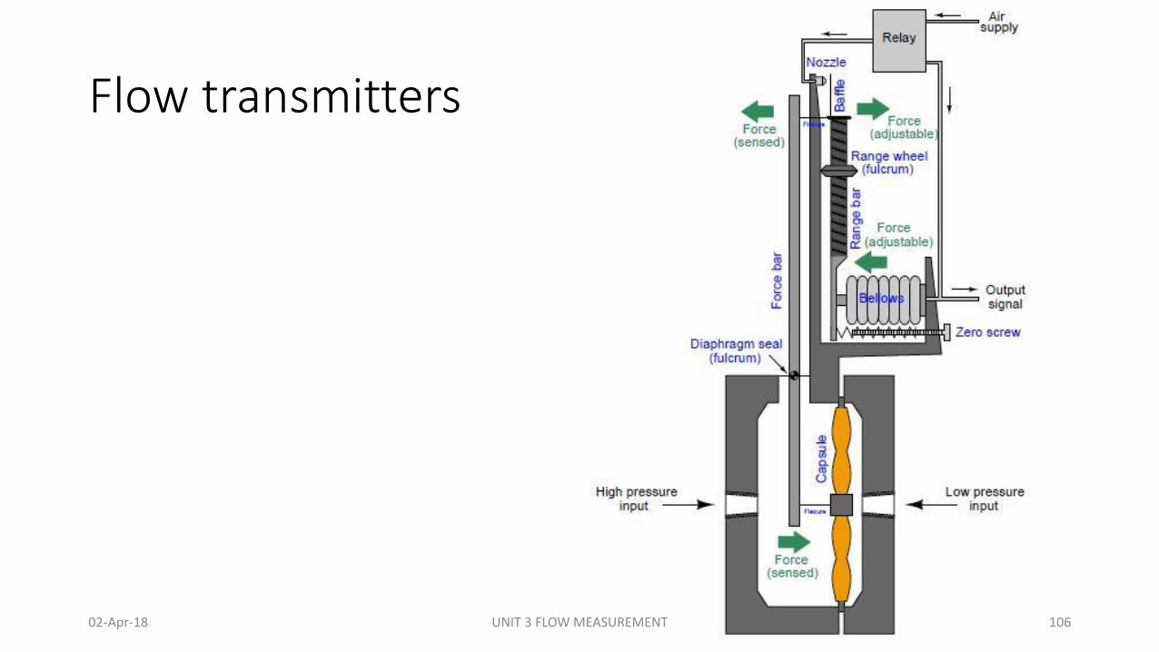
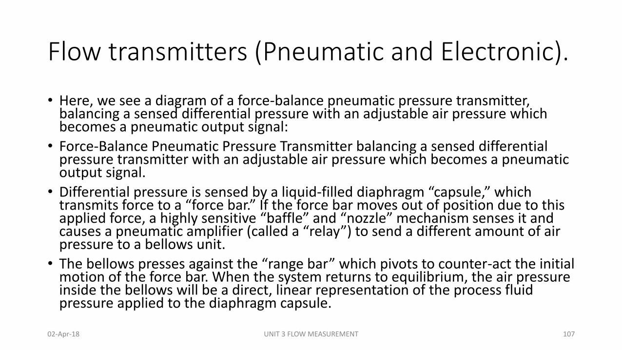
• Here, we see a diagram of a force-balance pneumatic pressure transmitter, balancing a sensed differential pressure with an adjustable air pressure which becomes a pneumatic output signal:
• Force-Balance Pneumatic Pressure Transmitter balancing a sensed differential pressure transmitter with an adjustable air pressure which becomes a pneumatic output signal.
• Differential pressure is sensed by a liquid-filled diaphragm “capsule,” which transmits force to a “force bar.” If the force bar moves out of position due to this applied force, a highly sensitive “baffle” and “nozzle” mechanism senses it and causes a pneumatic amplifier (called a “relay”) to send a different amount of air pressure to a bellows unit.
• The bellows presses against the “range bar” which pivots to counter-act the initial motion of the force bar. When the system returns to equilibrium, the air pressure inside the bellows will be a direct, linear representation of the process fluid pressure applied to the diaphragm capsule.
02-Apr-18 UNIT 3 FLOW MEASUREMENT 107
Flow transmitters
Electronic Differential Flow transmitter.
• It works on the principle of force balance by measuring differential pressure generated by orifice and converts differential pressure into flow.
• With minor modifications to the design of this pressure transmitter, we may convert it from pneumatic to electronic force-balancing:
• Differential pressure is sensed by the same type of liquid-filled diaphragm capsule, which transmits force to the force bar.
• If the force bar moves out of position due to this applied force, a highly sensitive electromagnetic sensor detects it and causes an electronic amplifier to send a different amount of electric current to a force coil.
• The force coil presses against the range bar which pivots to counteract the initial motion of the force bar. When the system returns to equilibrium, the mill ampere current through the force coil will be a direct, linear representation of the process fluid pressure applied to the diaphragm capsule.
02-Apr-18 UNIT 3 FLOW MEASUREMENT 108
Flow transmitters
Electronic Differential Flow transmitter.
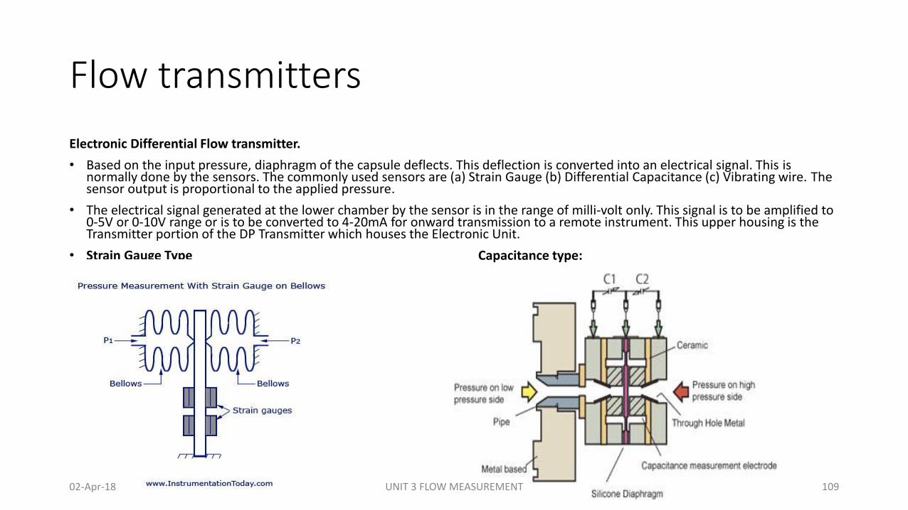
• Based on the input pressure, diaphragm of the capsule deflects. This deflection is converted into an electrical signal. This is normally done by the sensors. The commonly used sensors are (a) Strain Gauge (b) Differential Capacitance (c) Vibrating wire. The sensor output is proportional to the applied pressure.
• The electrical signal generated at the lower chamber by the sensor is in the range of milli-volt only. This signal is to be amplified to 0-5V or 0-10V range or is to be converted to 4-20mA for onward transmission to a remote instrument. This upper housing is the Transmitter portion of the DP Transmitter which houses the Electronic Unit.
• Strain Gauge Type Capacitance type:
02-Apr-18 UNIT 3 FLOW MEASUREMENT 109
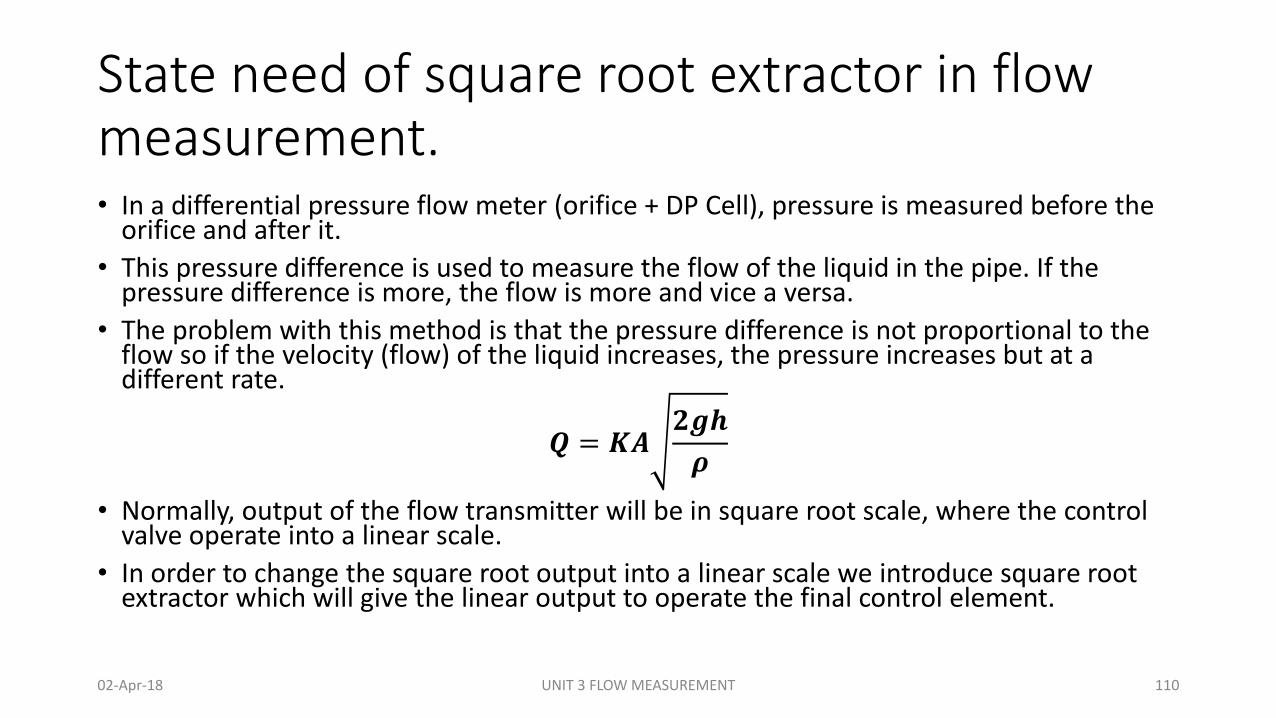
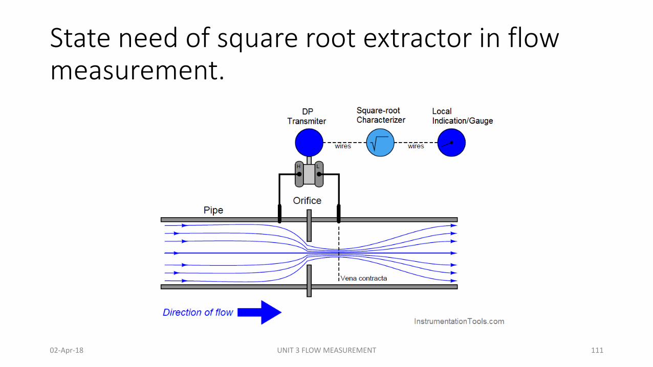
State need of square root extractor in flow measurement.• In a differential pressure flow meter (orifice + DP Cell), pressure is measured before the
orifice and after it.
• This pressure difference is used to measure the flow of the liquid in the pipe. If the pressure difference is more, the flow is more and vice a versa.
• The problem with this method is that the pressure difference is not proportional to the flow so if the velocity (flow) of the liquid increases, the pressure increases but at a different rate.
𝑸 = 𝑲𝑨𝟐𝒈𝒉
𝝆
• Normally, output of the flow transmitter will be in square root scale, where the control valve operate into a linear scale.
• In order to change the square root output into a linear scale we introduce square root extractor which will give the linear output to operate the final control element.
02-Apr-18 UNIT 3 FLOW MEASUREMENT 110
State need of square root extractor in flow measurement.
02-Apr-18 UNIT 3 FLOW MEASUREMENT 111
Considerations When Selecting a Flow Meter
1. Purpose & Application of the Flow Meter
• What exactly do you want the flow meter to accomplish? What are the requirements of the job at hand? What is the application type?
• In addition to these questions, it's also important to consider the category of flow measurement (liquids & gases), as that will help to define the type of sensor best suited in your respective environment. Similarly, identifying the place, or environment, where the flow meter will be used can help identify the size and range of the flow meter that will be necessary to achieve required accuracy.
2. Flow Profile of the Flow Meter
• What are the flow rates and characteristics of the liquids or gases for your application? Have you identified minimum and maximum flow rates for your application? What do you know about the performance qualities of the specific flow meter?
• Profile of the flow determines the momentum and other behaviors of fluid. Newtonian or non-Newtonian fluids have different viscosity, flow rate, pressure and velocity that will contribute to flowrates. It is important to be aware of these attributes to select the correct flow meter according to your specific requirements.
02-Apr-18 UNIT 3 FLOW MEASUREMENT 112
Considerations When Selecting a Flow Meter
3. Flow Meter Performance & Capabilities
• What size flow meter will be sufficient for your needs? Does the flow meter material or construction have any impact on the fluids of gases that you are moving? What about the pressure and temperature of the fluids and gas - how will that affect the performance of the flow meter or accuracy of measurement?
• Behavior of the flow meter is prominently defined by the Reynolds number. It is a dimensionless quantity which defines the relationship between momentum and velocity of fluid that can determine whether the flow or stream is laminar or turbulent. This flow meter attribute, along with the flow meter chemical compatibility (material), fluid pressure and temperature will help identify the performance capabilities and accuracy of the flow meter for the specific liquid or gas application.
4. External Factors
• What real life conditions may contribute to equipment downtime? Are their local environment or government regulations that might affect your operations? What about vendor selection?
• There are a host of environmental conditions and factors beyond your control that may affect everything from flow meter selection to operations. In addition, factors tied to the installation of the flow meter and the general lifespan of the equipment might also weigh in on the flow meter decision making process.
02-Apr-18 UNIT 3 FLOW MEASUREMENT 113
Considerations When Selecting a Flow Meter
5. Budget• What is the cost of the flow meter and related equipment? What about
installation and maintenance costs? What are the costs of operations? Have you considered the expected lifespan of the flow meter or depreciation values?
• You should plan to assign costs to the installation, preventative maintenance, repair, and running costs of a particular flow meter during the decision making process.
Flow Meters - Select the Right Instrument for Your Specific Application• Various parameters influence maintenance requirements and the life span
of flow meters. Keeping in mind all parameters will direct buyers and users to select the best suited flow meter for their respective application.
02-Apr-18 UNIT 3 FLOW MEASUREMENT 114
Assignment
• State importance of flow measurement in process industries.
• Enlist different type of flow and define any one.
• Give difference between turbulent and laminar flow.
• List units of Flow Measurements.
• What do you mean by reynold’s number?
• State Bernoulli’s theorem with equation.
• List types of Orifice plate.
• Explain detail construction for Orifice plate.
• Write merits and Demerits of Orifice Plate.
• List applications of orifice plate.
• Explain pressure profile through orifice plate with diagram.
• Explain working principle of Flow nozzle.
• List merits & demerits of flow nozzle.
• Draw figure of venture tube.
• Explain construction of venture tube.
• Write merits of venture tube.
• Define Stagnation point. Explain working principle of pitot tube.
• Explain construction of Pitot tube.
• Explain target flow meter.
• Draw figure of target and magnetic flow meter.
• Classify differential flow sensing element and explain any one.
02-Apr-18 UNIT 3 FLOW MEASUREMENT 115
Assignment
• Why rotameter is called variable area meter?
• Explain working principle of Rotameter.
• Explain construction and working of rotameter.
• List out merits and demerits of rotameter
• Explain working principle of Magnetic Flowmeter
• List out application of magnetic and mass flow meter
• Write merits and Demerits of Ultrasonic Flow meter.
• Explain Working principle of turbine flowmeter.
• List merits & demerits of turbine flow meter.
• Draw diagram of vortex flow meter.
• Explain working principle of vortex flowmeter.
• Explain working of vortex flow meter.
• Explain ultrasonic flow meter in detail with diagram.
• List merits and demerits of ultrasonic flowmeter.
• Write types of positive displacement meter.
• List various types of flow switch.
• State need of square root extractor in flow measurement.
• Draw diagram of Mass flow meter.
• Explain pneumatic type flow transmitter.
• Discussed about factor consideration for flow meter selection.
02-Apr-18 UNIT 3 FLOW MEASUREMENT 116

Thanks