Unit 3 Design for Manufacturing and Assembly
99
Unit 3 Design for Manufacturing and Assembly Presented By: Akshay Shah Assistant Professor Indus University 1
Transcript of Unit 3 Design for Manufacturing and Assembly

Unit 3
Design for Manufacturing and
Assembly
Presented By:
Akshay Shah
Assistant Professor
Indus University
1

• Design for Manufacture (DFM): Design of components taking into
consideration the processes that will be used to manufacture
them to ensure that manufacturing costs are minimized.
• Design for Assembly (DFA): Design of the product for ease of
assembly.
• Design for manufacture and Assembly (DFMA): DFA + DFM.
DFMA Definition

• DFMA shortens the time to bring the product to market
• DFMA reduces product costs
Example of DFMA

• Reduces the time to market and quality of the product.
• Provides a systematic procedure for analysing a proposed design from the
point of view of assembly and manufacture.
• Any reduction in the number of parts reduces the cost as well as the inventory
• Increases Reliability
Advantages of DFMA

Steps involved in DFMA

• No time: Designers are constrained to minimize their “design to manufacture
time” for a new product.
• The ugly baby syndrome: Designer ego crashes if there is some suggestion for
design change.
• Low assembly cost: Since assembly cost of a particular product is less as
compared to the total material and manufacturing cost, DFA analysis is not
required.
• Low volume: Often it is expressed that DFMA is applicable for large quantity
production.
• Refuse to use DFMA: Individual doesn't have the incentive to adopt the new
technology and use the tools available.
Reasons for not using DFMA
7
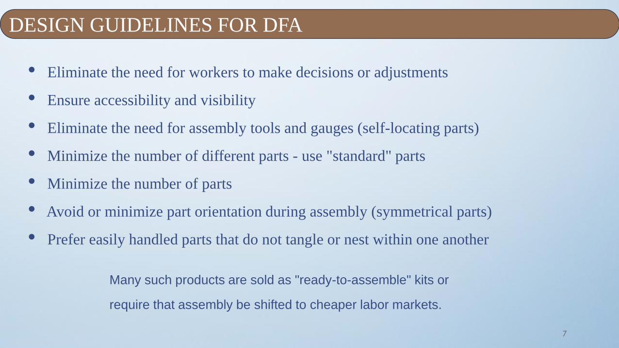
• Eliminate the need for workers to make decisions or adjustments
• Ensure accessibility and visibility
• Eliminate the need for assembly tools and gauges (self-locating parts)
• Minimize the number of different parts - use "standard" parts
• Minimize the number of parts
• Avoid or minimize part orientation during assembly (symmetrical parts)
• Prefer easily handled parts that do not tangle or nest within one another
Many such products are sold as "ready-to-assemble" kits or
require that assembly be shifted to cheaper labor markets.
DESIGN GUIDELINES FOR DFA

8
• The process of DFA can be divided into two separate areas:
1. Handling (acquiring, orienting, and moving the parts)
2. Insertion and Fastening (mating a part to another part
or group of parts)
GENERAL DESIGN GUIDELINES FOR MANUAL ASSEMBLY [1]

9
a) Parts must have end-to-end symmetry and rotational
symmetry about the axis of insertion.
b) Part cannot be made symmetric, are obviously asymmetric.
c) Provide features that will prevent jamming of parts that tend
to nest or stack when stored in bulk
d) Parts which can tend to nest or stack when stored in bulk,
e) Parts must be tangled free
f) Avoid parts that are sharp and splinter easily.
(f)
PART HANDLING

10
1. Design so that there is little or no resistance to insertion and provide chamfers to guide
insertion of two mating parts.
FOR INSERTION AND FASTENING

11
2. Standardize of Parts, Processes and Methods across all models.
3. Use pyramid assembly
4. Avoid the necessity for holding parts down to maintain their
5. orientation during manipulation of the subassembly.
6. Design so that a part is located before it is released.
7. Cost of different fastening processes.
(c)(b)
(a)
Cont.…..

12
(d)
(e)
i. a. Snap fitting
ii. b. Plastic bending
iii. c. Riveting
iv. d. Screw fastening
Cont…

13
1. Avoid connections 2. Avoid adjustments
A
B
A A A
B
B B
FURTHER DESIGN GUIDELINES

14
3. Design so that access for assembly operations is not restricted

15

Design Efficiency
• Design Efficiency is the number of essential parts divided by the
total number of parts, expressed as a percentage:
𝐴
𝐴 + 𝐵× 100%
• The Lucas methodology labels parts as ‘A’ (essential) and ‘B’
(target for designing out).
• Boothroyd& Dewhurst use ‘1’ and ‘0’, but the result is similar.
16

Low budget version
17

18

19

20

21

22

23

Result Analysis of DFA
Eleven parts were found essential (A):
• The box the toy came in
• The ceiling mount plate, swivel and cable
• The upper and lower body mouldings
• The motor, and attached fan
• The switch
• The spring steel battery contacts (3 parts)
Total there were 30 parts (A+B)
24
Design Efficiency
𝐴
𝐴+𝐵× 100% =
11
30× 100%
= 36.7 %

Making use of Design Efficiency
• Some companies use design efficiency as a decision gate (for
example, proceed with the design if efficiency is over 45%)
• Use design efficiency to compare two or more alternative design
concepts, and go with the best one
• Examine each ‘B’ part in turn, and state how it might be
designed out (if reasons such as manufacturing complexity
prevent its elimination, record the reasons)
25

TYPICAL DFMA CASE STUDIESDefense Industry
• Figure shows original design of a reticleassembly for a thermal gun sight usedin a ground-based armored vehicle.
• Used to track and sight targets atnight, under adverse battlefieldconditions, and to align the videoportion of the system with thetrajectory path of the vehicle'sweapon to ensure accurate remotecontrolled aiming.
26

TYPICAL DFMA CASE STUDIESDefense Industry
• The new design was analyzed usingDFA
• Table 1.5: results for original designand for redesign.
• In the original design there were 24different parts and in the new designonly eight.
• 16 part types has been eliminated.
27

TYPICAL DFMA CASE STUDIESDefense Industry
28

29

Design features to facilitate :
Machining
Milling - Cutters
Drills
Keyways
Design for Assembly - Machining Considerations 30
Tab
le
of
Co
nte
nt

Design for Assembly - Machining Considerations 31

Design for Assembly - Machining Considerations 32
Design features to facilitate Machining [1]:
1 Avoid machining operations if possible.
2 Part should be easy for fixturing and secure holding.
Work piece For planner
machineX
Design for Assembly - Machining Considerations 33
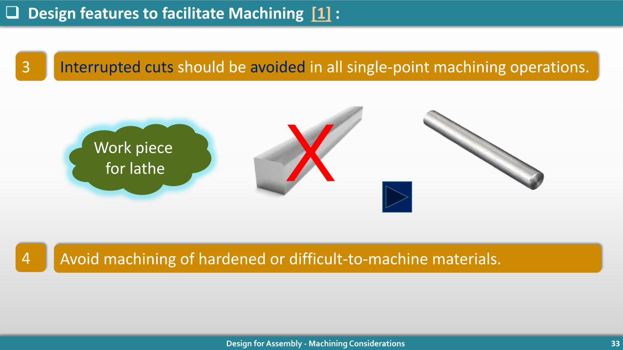
Design features to facilitate Machining [1] :
Interrupted cuts should be avoided in all single-point machining operations.
Avoid machining of hardened or difficult-to-machine materials.
Work piece for lathe
3
4
X

Design for Assembly - Machining Considerations 34
Design features to facilitate Machining [1] :
Parts should be rigid enough to withstand the forces of clamping andmachining without distortion
Provide sufficient allowances to the stock for both rough and finishmachining.
Work piece to be clamped
in lathe chuck
5
6
X

Design for Assembly - Machining Considerations 35
Design features to facilitate Machining [1] :
Number of operations required are reduced by using the same plane forsubsequent machining.
Avoid undercuts to avoid separate operation of specially ground tools.
7
8
XX

Design for Assembly - Machining Considerations 36
Design features to facilitate Machining [1] :
Provide access room for cutters bushing and fixture.
10 Avoid parting lines or draft surfaces for clamping or locating surfaces.
9
11 Provide relief space for burr removal.
12 Work piece should permituse of standard cutters.
XX
Design for Assembly - Machining Considerations 37
Design for Assembly - Machining Considerations 38
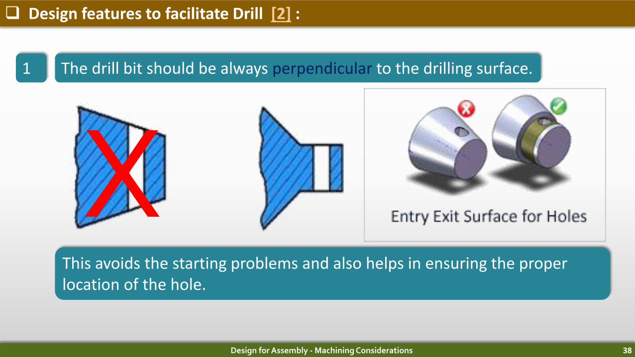
Design features to facilitate Drill [2] :
1 The drill bit should be always perpendicular to the drilling surface.
This avoids the starting problems and also helps in ensuring the properlocation of the hole.
X

Design for Assembly - Machining Considerations 39
Design features to facilitate Drill [2] :
2 Avoid interrupted cut when straightness of hole is important.
It is advised to use a guide bushat each re-entry surface.
The center point of the drill mustremain in the work piecethroughout the cut.
X

Design for Assembly - Machining Considerations 40
Design features to facilitate Drill [2] :
3 Through holes are preferable than blind holes. It provides clearance to thetool and chip in secondary operations like reaming, tapping, or honing.
4 The drill bit always generates pointed holes in blind holes. Flat bottoms arecostlier in blind holes as secondary operations are required.
Costly Better Best

Design for Assembly - Machining Considerations 41
Design features to facilitate Drill [2] :
5 Recommended depth of the hole is maximum 3 times that of the diameterof the hole.
If it is more, it creates chip clearanceproblems and the possibility ofdeviations from straightness.
Special tooling, equipment andtechniques are used for deep holedrilling.
For example, Gun barrel boredholes can be as deep as 5 timesthat of the hole diameter.

Design for Assembly - Machining Considerations 42
Design features to facilitate Drill [2] :
6 A minimum diameter about 3mm is preferred for hole drilling as smalldiameter drills are more prone to breakage.
7 It is required to dimension holes from the same surface to simplifyfixturing.
Dimensioning from
different surface
Dimensioning from
Same surface
Design for Assembly - Machining Considerations 43
Design features to facilitate Drill [2] :
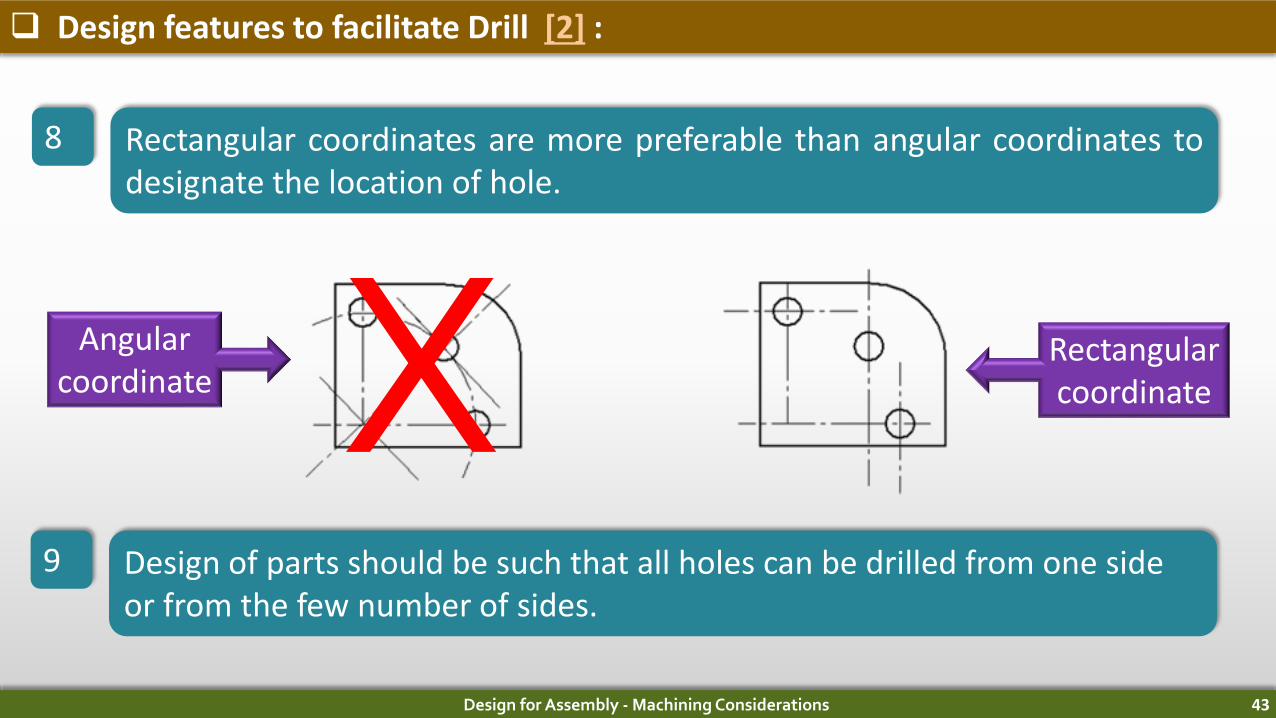
8 Rectangular coordinates are more preferable than angular coordinates todesignate the location of hole.
9 Design of parts should be such that all holes can be drilled from one side or from the few number of sides.
Angularcoordinate
RectangularcoordinateX

Design for Assembly - Machining Considerations 44
Design features to facilitate Drill [2] :
10 Allow room for drill bushings close to the work piece surface to be drilled.
11 For multiple-drilling arrangements, the spacing between the holes shouldnot be less than 19 mm for small holes.
Design for Assembly - Machining Considerations 45

Design for Assembly - Machining Considerations 46
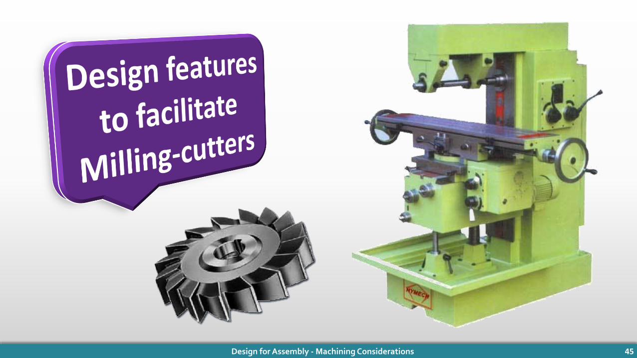
Design features to facilitate Milling-cutters [3] :
1 Use standard cutter shapes and sizes.
Specialized nonstandard cutters arecostly and difficult to maintain. XX

Design for Assembly - Machining Considerations 47
Design features to facilitate Milling-cutters [3] :
2 Product design should permit the use of the radii provided by the cuttingtool.

Design for Assembly - Machining Considerations 48
Design features to facilitate Milling-cutters [3] :
3 Allowing a beveled rather than a rounded corner for more economicalmachining.
Corner rounding
cutter
Facemill
Do
Don’t

Design for Assembly - Machining Considerations 49
Design features to facilitate Milling-cutters [3] :
4 Use standard cutter to produce both sides and ends of keyways in oneoperation.
5 Avoid milling at parting lines, flash areas, and weld-ments for higher cutterlife.

Design for Assembly - Machining Considerations 50
Design features to facilitate Milling-cutters [3] :
6 Surfaces in the same plane or at least in the same direction and in parallel planes are preferred.
7 End-milling slots in mild steel shouldnot be deeper than the diameter ofthe cutter.

Design for Assembly - Machining Considerations 51
Design features to facilitate Milling-cutters [3] :
8 Form milling is an economical approach if product design permits stackingor slicing operations.
Stacked and milled
Un -stacked

Design for Assembly - Machining Considerations 52

Design for Assembly - Machining Considerations 53
Design features to facilitate Keyways [4]:
1 For generating external keyways, end milling cutter or a slotting cutter hasto be used and can be done much faster compared to other processes.
To suit a cutting tool, blind axial keyways should be radiused at the end.

Design for Assembly - Machining Considerations 54
Design features to facilitate Keyways [4] :
2 Width of keyways should be such that standard cutters can be used.
3 If the end of keyway is radiused in such away that it could be cut by a slotting cutter,it will improve the speed of machiningkeyways.

Design for Assembly - Machining Considerations 55
Design features to facilitate Keyways [5] :
4 Milling and shaping is not recommended for internal keyways generation.
For internal keyways, broaching machine should be used.
Horizontal Broaching Machine
VerticalBroaching Machine

Design for Assembly - Machining Considerations 56
Design features to facilitate Keyways [5] :
5 For keyways in hardened material, wire-cut EDM is recommended.
Wire-cut EDM
Broaching and wire-cut EDM can’t beused for blind keyway.

DESIGN GUIDELINES FOR
WELDING

Introduction
• Arc welding can be used to weld almost any kind of
assembly.
• Commonly produced devices by arc welding are tube
fittings, storage tanks, pressure vessels, machine frames,
structures for industrial equipment, railroad cars etc.

Design guidelines for welding
• Welded assemblies should have few parts.
• Weld joints should be placed in such a way that there is easy access of the
welding nozzle.
• Provide minimum amount of weld filler, with respect to both fillet size and
length that meets functional requirements of the assembly.
• Welding should be done horizontally, with the stick or electrode holder
pointing downward during welding

Design guidelines for welding• Product design should minimize the number of welds because, unless
automated.
• Weld location should be selected so as to avoid excessive stresses or
stress concentrations in the welded structure and for appearance.
• Components should fit properly prior to Welding. The method used to
prepare edges, such as sawing, machining, or shearing, also can affect
weld quality.
• The need for edge preparation should be avoided or minimized.
• Weld-bead size should be as small as possible, While maintaining the
strength of the joint, to conserve Weld metal and for better appearance

Design guidelines for Welding
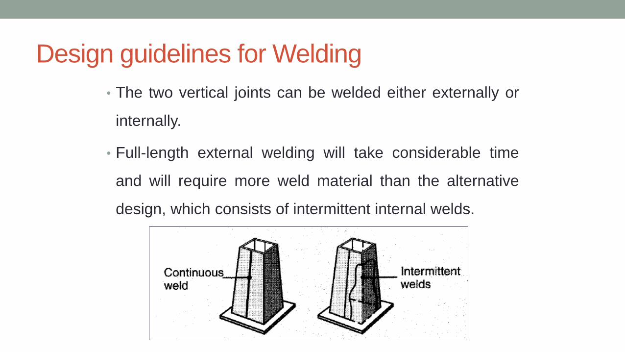
• The two vertical joints can be welded either externally or
internally.
• Full-length external welding will take considerable time
and will require more weld material than the alternative
design, which consists of intermittent internal welds.

Design Guidelines for welding
• Design on the right can carry 3 times the moment ‘M’ of the one on the left.
• Both designs require the same amount of weld metal and Welding time.

Design guidelines for welding
• Left side welding - weld metal is twice the amount of weld material than
welding on the right.
• Edge preparation for left side weld requires more time than on right side
because of more material

Design guidelines for welding
• The designer should be aware of poor and good fit-up of parts at the weld
joint. It is essential not only for welding speed but also for minimizing distortion
of the finished weldment.

Design guidelines for welding
• The build-up of weld fillets should be kept to a minimum as it doesn’t add
significant strength to the joint
• If Forgings or castings are part of a welded assembly, one should ensure good
fit-up of the parts to be welded. For example untrimmed parting-line areas
shouldn’t be included in the welded joint.
• In the cast part the wall thickness of both parts to be joined should be equal
at the joint.

Design guidelines for welding

Design guidelines for welding
• The joint should be designed so that it requires minimal edge preparation.
For this, one should use slip or lap joints in welded assemblies to avoid the
cost of close edge preparation and to simplify fit-up problems.

Design guidelines for welding
• If machining after welding is
required, it is advisable to place
welds away from the material
to be machined to avoid
machining problems.
• In the second figure the welded
portion on right side is not
desirable because the hole to
be bored will be difficult.

Design guidelines for welding
• Sometimes it is advantageous to include a weld backup strip as an integral part of one of the
component to be welded.
• Short flanged butt joints are preferable to join thin materials. Unless joints have good
supports long sections of thinner material, when welded together, are apt to distort and buckle.

Design guidelines for welding
• If possible, place welds opposite one
another to reduce distortion.
• If sections of unequal thickness are to
be welded, distortion can be reduced by
equalizing wall thickness at the joint by
machining a groove in the thicker piece
adjacent to the weld joint

DESIGN GUIDELINES FOR PLASTICS,
RUBBER AND CERAMIC

Plastics• A polymer is a compound consisting of long-chain
molecules, each molecule made up of repeating units
connected together
• Polymers can be separated into plastics and rubber. As
engineering materials, they are relatively new compared
to metals and ceramics, dating only from around the mid-
1800s.

Design guidelines for Plastic
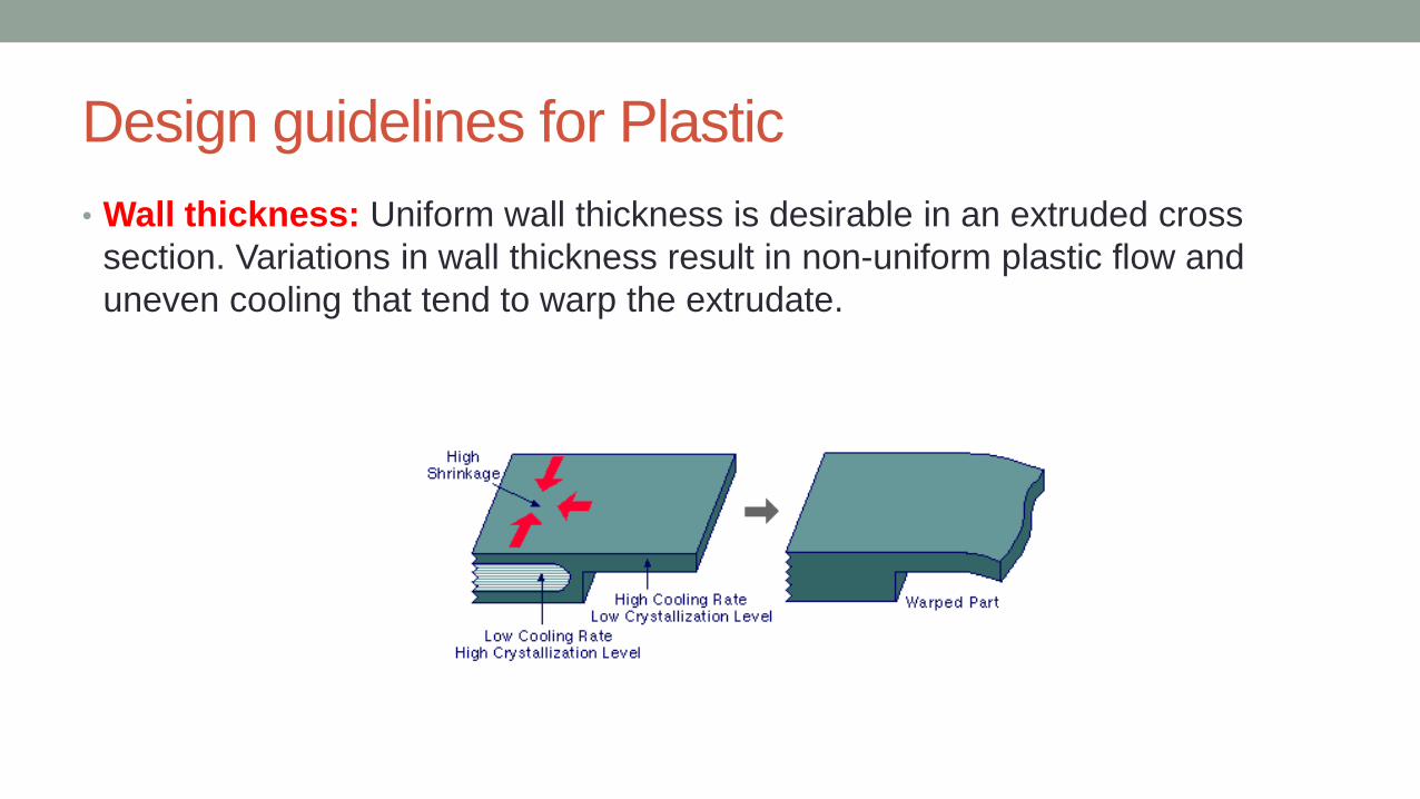
• Wall thickness: Uniform wall thickness is desirable in an extruded cross
section. Variations in wall thickness result in non-uniform plastic flow and
uneven cooling that tend to warp the extrudate.

Design guidelines for Plastic
• Always try to keep wall thickness uniform
• There should be gradual transition between changing sections.
• Wall thickness for reinforced materials 0.75 mm to 3 mm and for unreinforced
material it is 0.5 mm to 5 mm

Design guidelines for Plastic
• Hollow sections complicate die design and plastic flow. It is desirable to use
extruded cross sections that are not hollow yet satisfy functional requirements
Design guidelines for Plastic
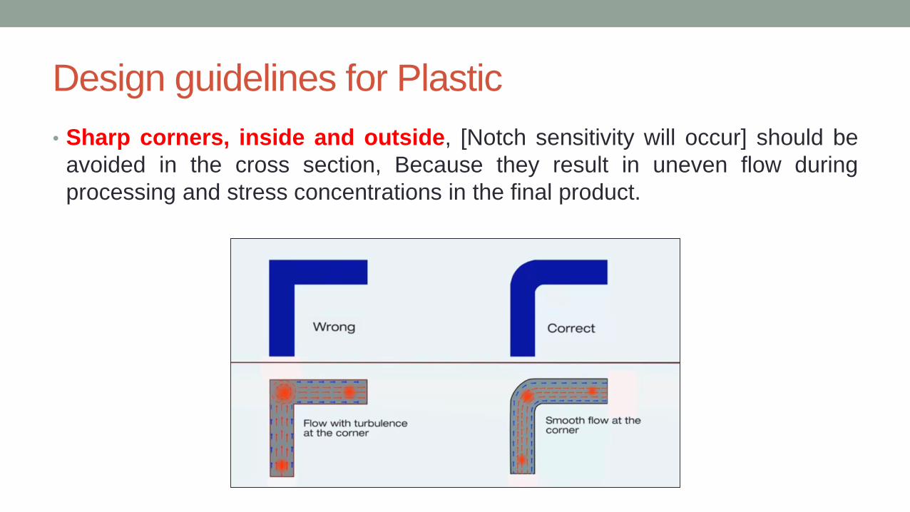
• Sharp corners, inside and outside, [Notch sensitivity will occur] should be
avoided in the cross section, Because they result in uneven flow during
processing and stress concentrations in the final product.

Design guidelines for Plastic
• Economic production quantities: Each molded part requires a unique mold,
and the mold for any of these processes can be costly, particularly for injection
molding.
Process Minimum number of pieces
Injection Molding > 10000
Transfer Molding 1000 to 10000
Compression molding >1000

Manufacturing of rubber

Design guidelines for Rubber
• Economic production quantities. Rubber parts produced by compression
molding (the traditional process) can often be produced in quantities of a
thousand or less.
• The mold cost is relatively low compared with other molding methods.
Injection molding, as with plastic parts, requires
• Draft is usually unnecessary for rubber molded parts. The flexibility of the
material allows it to deform for removal from the mold.
• The low stiffness and high elasticity of the material permits removal from the
mold.
• Holes are difficult to cut into the rubber after initial forming, due the flexibility
of the material. It is generally desirable to mold holes into the rubber during
the primary shaping process.

Design considerations for ceramics
• Ceramic components should be designed to be subjected to compressive
stresses, not tensile stresses.
• Ceramic parts should not be used in applications that involve impact loading
or high stresses that might cause fracture.
• Deep holes, channels, and undercuts should be avoided,
• Part shrinkage in drying and firing (for traditional ceramics) and sintering (for
new ceramics) may be significant and must be taken into account by the
designer in dimensioning and tolerancing
• Screw threads in ceramic parts should be avoided.

Design Consideration for castings

Introduction
• Variables in Casting process: characteristics of the metals (or alloys) casts, method of
casting, mold/die materials, mold/die design.
• The flow of the molten metal in the mold cavities, the gating systems, the rate of
cooling, and the gases evolved all influence the quality of a casting.
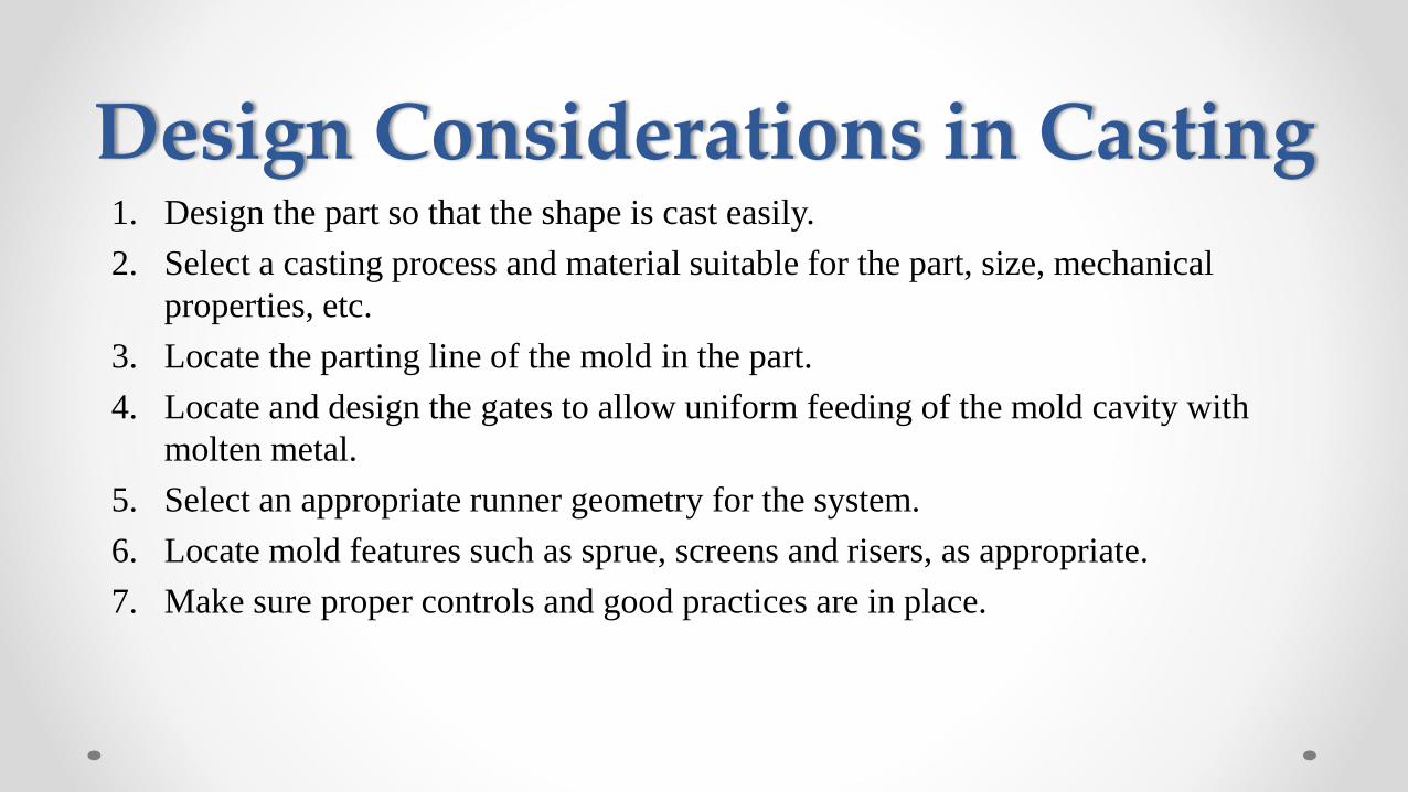
Design Considerations in Casting1. Design the part so that the shape is cast easily.
2. Select a casting process and material suitable for the part, size, mechanical
properties, etc.
3. Locate the parting line of the mold in the part.
4. Locate and design the gates to allow uniform feeding of the mold cavity with
molten metal.
5. Select an appropriate runner geometry for the system.
6. Locate mold features such as sprue, screens and risers, as appropriate.
7. Make sure proper controls and good practices are in place.

Why design considerations for casting?

Design Considerations in Casting
• Corners, angles and section thickness: avoid using sharp corners and angles (act as
stress raisers) and may cause cracking and tearing during solidification. Use fillets
with radii ranging from 3 to 25 mm

Design Considerations in Casting• Sections changes in castings should be blended smoothly into each other.
• Because the cooling rate in regions with large circles is lower, they are called hot
spots.
• Cavities at hot spots can be eliminated by using small cores (e).
Design Considerations in Casting
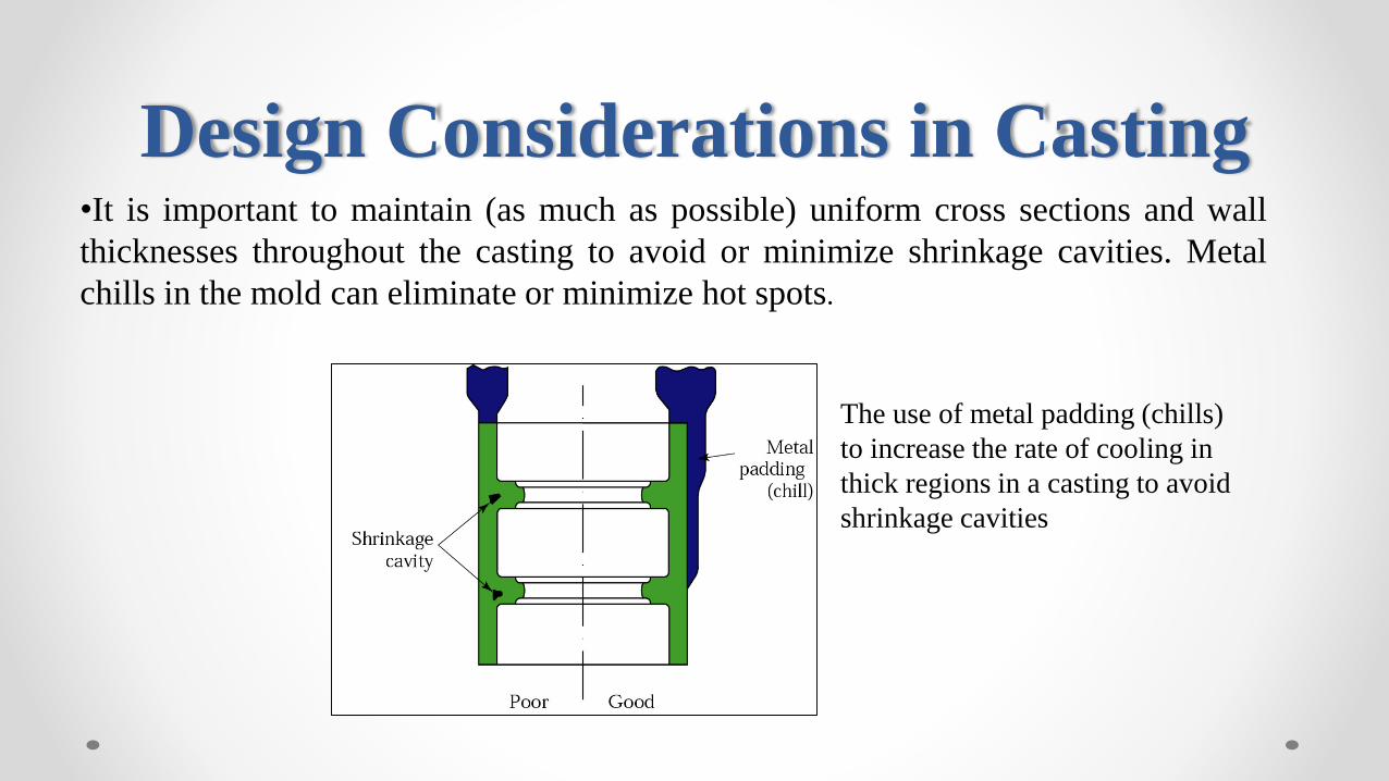
The use of metal padding (chills)
to increase the rate of cooling in
thick regions in a casting to avoid
shrinkage cavities
•It is important to maintain (as much as possible) uniform cross sections and wall
thicknesses throughout the casting to avoid or minimize shrinkage cavities. Metal
chills in the mold can eliminate or minimize hot spots.

Design Considerations in Casting
• Draft: a small draft (taper) typically is provided in sand mold pattern to enable
removal of the pattern without damaging the mold. Depending on the quality of the
pattern, draft angles usually range from 0.5o to 2o.
• Dimensional tolerances: tolerances should be as wide as possible, within the limits
of good part performance; otherwise, the cost of the casting increases. In commercial
practices, tolerances are usually in the range of ± 0.8 mm for small castings. For
large castings, tolerances may be as much as ± 6 mm.

Design Considerations in Casting
• Lettering and markings: it is common practice to include some form of part
identification (such lettering or corporate logos) in castings. These features can be
sunk into the casting or protrude from the surface.
• Machining and finishing operations: should be taken into account. For example, a
hole to be drilled should be on a flat surface not a curved one. Better yet, should
incorporate a small dimple as a starting point. Features to be used for clamping
when machining.
Design Considerations in Casting -Locating the parting line
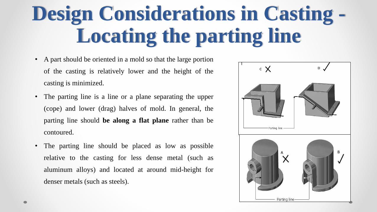
• A part should be oriented in a mold so that the large portion
of the casting is relatively lower and the height of the
casting is minimized.
• The parting line is a line or a plane separating the upper
(cope) and lower (drag) halves of mold. In general, the
parting line should be along a flat plane rather than be
contoured.
• The parting line should be placed as low as possible
relative to the casting for less dense metal (such as
aluminum alloys) and located at around mid-height for
denser metals (such as steels).

Design Considerations in Casting -Locating the parting line
Figure 12.5 Redesign of a casting by making the parting line
straight to avoid defects.

Factors affecting selection of parting direction and parting line
• Draft- To facilitate removal of manufactured component
from mould the cross-sectional area should gradually
decrease from the parting surface in parting direction.
• Necessary draft has to be applied to the part in the
parting direction if the projected area does not decrease
on the parting direction.
• An optimal parting direction and line will have
minimum possible draft.

Factors affecting selection of parting direction and parting line
• Flash- Material flowing into gaps at the plane of separation ofthe two mould halves produces fin like protrusions or flashand is treated as imperfection.
• This is generally trimmed after manufacturing. For optimalparting direction and parting line the flash must be less andeasy to trim.
• Flatness- The selection of the parting direction shouldensure the flatness of the parting line.
• A flat parting line alone can take care of the other aspectslike side thrust, dimensional stability, sealing off, flash etc.
• The complexity of a non-flat parting line should beminimum possible

Decision criteria for parting line selection
• Factors affecting parting line selection are rated according to high, medium and low
priority.
• The criteria with high priority are number of undercuts, draft, projected area and
dimensional stability.
• Criteria with medium priority are draw, flash, flatness and placement of ejector pins.
• The criteria with low priority are side thrust, placement of overflow wells, trimming
and finishing operations, scrap generated.

Change in Parting Line
The example shown in figure indicates the
effect of Air Pressure in the cavity before (~3.8
bar) and after changing the parting line (~1.8
bar) in the product design. The customer
requirement was porosity level 1 as per ASTM
E 505.Source: ALUCAST India
Solidification Time – Before (10 Sec) and after (8 Sec) change in shape of the boss

Additional rib for providing material flow
The following example indicates how the addition of ribs change the filling pattern and
sudden change in cross section to improve the material filling and reduce the air
pressure in the cavity. This has helped to reduce the cold fill and shrink porosity.
Source: ALUCAST India
Air Pressure – Before (3.8 bar) and after 1.8 bar) change in parting line near the boss.

99