UNIT 1- INTRODUCTION TO POWER GENERATION · UNIT 1- INTRODUCTION TO POWER GENERATION INTRODUCTION...
67
UNIT 1- INTRODUCTION TO POWER GENERATION INTRODUCTION Whenever, we are going to study about the power plants, we must know about the sources of energy. In this unit, we will be discussing the concepts of various power plants, their advantages and disadvantages. Fuels used in the power plants. The important fuels used in the power plants like, coal, diesel, steam, uranium, etc. are also clearly described here. Objectives After studying this unit, you should be able to understand the concept of power plant , understand the types of power plants, know the types of fuels, and describes the main components of power plants SOURCES OF ENEGY – FUELS There are many different ways in which the abundance of energy around us can be stored, converted, and amplified for our use. To help understand the key energy sources that will play an important role in the world‘s future, it is required to familiarize with some of the history, theory, economics, and problems of the various types of energy. The energy sources have been split into three categories: fossil fuels, renewable sources, and nuclear sources. The fossil fuels here are coal, petroleum, and natural gas. The renewable energy sources are solar, wind, hydroelectric, biomass, and geothermal power. The nuclear- powered sources are fission and fusion. Types of Fuels Fossil Fuels Fossil fuels have been a widely used source of energy ever since the Industrial Revolution just before the dawn of the 20th century. Fossil fuels are relatively easy to use to generate energy because they only require a simple direct combustion. However, a problem with fossil fuels is their environmental impact. Not only does their excavation from the ground significantly alter the environment, but their combustion leads to a great deal of air pollution.
Transcript of UNIT 1- INTRODUCTION TO POWER GENERATION · UNIT 1- INTRODUCTION TO POWER GENERATION INTRODUCTION...

UNIT 1- INTRODUCTION TO POWER GENERATION
INTRODUCTION
Whenever, we are going to study about the power plants, we must know about the sources of energy. In
this unit, we will be discussing the concepts of various power plants, their advantages and disadvantages.
Fuels used in the power plants. The important fuels used in the power plants like, coal, diesel, steam,
uranium, etc. are also clearly described here. Objectives After studying this unit, you should be able to
understand the concept of power plant
, understand the types of power plants,
know the types of fuels, and
describes the main components of power plants
SOURCES OF ENEGY – FUELS
There are many different ways in which the abundance of energy around us can be stored, converted, and
amplified for our use. To help understand the key energy sources that will play an important role in the
world‘s future, it is required to familiarize with some of the history, theory, economics, and problems of
the various types of energy. The energy sources have been split into three categories: fossil fuels,
renewable sources, and nuclear sources. The fossil fuels here are coal, petroleum, and natural gas. The
renewable energy sources are solar, wind, hydroelectric, biomass, and geothermal power. The nuclear-
powered sources are fission and fusion.
Types of Fuels
Fossil Fuels
Fossil fuels have been a widely used source of energy ever since the Industrial Revolution just before the
dawn of the 20th century. Fossil fuels are relatively easy to use to generate energy because they only
require a simple direct combustion. However, a problem with fossil fuels is their environmental impact.
Not only does their excavation from the ground significantly alter the environment, but their combustion
leads to a great deal of air pollution.

Theory
The theory behind fossil fuels is actually quite simple. Burning coal, natural gas, and petroleum releases
energy stored in the fuel as heat. The energy contained by the fuels is derived from the energy of the sun.
The heat that is recovered upon combustion of the fuel can be used by us in several ways. Industrial
processes that require extremely high temperatures may burn a great deal of very pure coal known as
―coke‖ and use the energy released to directly heat a system. Some people make use of clean burning
natural gas to heat their homes. Combustion of fossil fuels can also be used to generate electricity; the
fuel is burned to heat water, and the steam from the boiling water spins turbines that power a generator,
thereby manufacturing electricity:
COAL\
About 300 million years ago, enormous ferns and other prehistoric plants were common on the swamp-
like earth. When those plants died and fell to the ground, they were covered with water and they slowly
decomposed. As decomposition took place in the absence of oxygen, much of the hydrogen content of the
matter was eroded away, leaving a material rich in carbon. The material was compressed over the years
by sand and dirt, leaving the form of carbon known as coal.
Types

The nature of coal is such that the higher the carbon content, the more cleanly and brilliantly the coal
burns. Thus ―peat‖, which is the state of the decomposing plants before being compressed, is a weak,
impure substance. The other states of coal from lowest carbon content to highest are lignite, bituminous
coal, and anthracite coal. If the coal is heated and compressed even more, the result is graphite, almost
completely pure carbon. Nearly all the different forms of coal are used in some way or another. For
instance, peat has been used for burning in furnaces, whereas bituminous coal is used extensively for the
generation of electricity. ―Coke‖, a very pure form of coal with high heat content is used primarily in the
steel industry, where high temperatures are required.
POLLUTION
Global Warming
Scientists believe that global warming is caused by the Greenhouse effect. The greenhouse effect
describes the accumulation of carbon dioxide in our earth‘s atmosphere. A layer of gas forms that traps
heat inside the atmosphere, thereby acting as the glass ceiling of a greenhouse. Because heat is trapped by
the carbon dioxide, it is believed that the earth is slowly warming. A potential danger of global warming
is the melting of the so-called polar ice caps at the north and south poles. This occurrence would cause the
ocean level to rise and perhaps flood many coastal cities.
The Advent of Fossil Fuels
Before humans were around on the earth, there was a relatively even recycling of carbon dioxide and
oxygen. Plants require carbon dioxide to live, and they emit oxygen in return. Animals, on the other hand,
need oxygen, but exhale carbon dioxide. But as humans began to burn fossil fuels to create energy
(especially beginning just before the 20th century during the Industrial Revolution), more and more
carbon dioxide was emitted into the air until the balance was slowly destroyed. How Do Fossil Fuels and
Biomass Pollute? All fossil fuels and biomasses consist of carbon and hydrogen atoms. When these fuels
are burned, or combusted, carbon atoms unite with oxygen in the air to form carbondioxide :
Other Polluting
Byproducts of Fossil Fuel and Biomass Burning Carbon dioxide is not the only byproduct of direct
combustion of fuel. Small particulates that can become imbedded in the human respiratory system are
also emitted. Particulates can cause coughing and damage to the lungs. Further, they can lead to cancer
and lung disease.

Carbon monoxide is produced when less oxygen is available in the immediate area. Carbon monoxide is
more directly harmful to humans because it is odorless, colorless, and reduces the body‘s ability to
transport oxygen. This leads to fatigue, nausea, and headaches.
The Spectrum of Pollution
Materials on the low end of the energy scale such as wood and charcoal create the most pollution. Sources
on the high end of the energy scale, such as natural gas burn very cleanly resulting in less air pollution.
HYDROELECTRIC
Man has utilised the power of water for years. Much of the growth of early colonial industry can be
attributed to hydropower. Because fuel such as coal and wood were not readily available to inland cities,
settlers were forced to turn to other alternatives. Falling water was ideal for powering sawmills and grist
mills. As coal became a better-developed source of fuel, however, the importance of hydropower
decreased.
Theory
Hydroelectric systems make use of the energy in running water to create electricity. In coal and natural
gas systems, a fossil fuel is burned to heat water. The steam pressure from the boiling water turns
propellers called turbines. These turbines spin coils of wire between magnets to produce electricity.
Hydro powered systems also make use of turbines to generate electrical power; however, they do so by
using the energy in moving water to spin the turbines. Water has kinetic energy when it flows from higher
elevations to lower elevations. The energy spins turbines like as shown in Figure 1.3. In larger scale
hydroelectric plants, large volumes of water are contained by dams near the generator and turbines. The
―forebay‖ is a storage area for water that must be deep enough that the penstock is completely submerged.
The water is allowed to flow into the electricity-generating system through a passage called the penstock.
The controlled high-pressure water spins the turbines, allowing the generator to produce an electric
current. The powerhouse contains and protects the equipment for generating electricity. The high-pressure
water exits the system through a draft tube. The fish ladder attempts to minimise the environmental
impact of hydroelectric systems by providing a path for migrating fish to take

Types of Hydroelectric Power Plants
Micro-Scale
As their name implies, micro-hydroelectric plants are the smallest type of
hydroelectric energy systems. They generate between one kilowatt and one
megawatt of power. The main application for these hydro systems is in small,
isolated villages in developing countries. They are ideal for powering smaller
services such as the operation of processing machines.
Small-Scale
Small hydropower systems can supply up to 20 megawatts of energy. These
systems are relatively inexpensive and reliable. They have the potential to provide
electricity to rural areas in developing countries throughout the world. Small
systems are especially important to countries that may not be able to afford the
costs of importing fossil fuels such as petroleum from other countries.
Run-of-the-River
In some areas of the world, the flow rate and elevation drops of the water are
consistent enough that hydroelectric plants can be built directly in the river. The
water passes through the plant without greatly changing the flow rate of the river.

In many instances a dam is not required, and therefore the hydroelectric plant
causes minimal environmental impact on its surroundings. However, one problem
with run-of-the-river plants is the obstruction of fish and other aquatic animals.
This and other problems are discussed in the next section.
Problems with Hydroelectric Power
Although hydroelectric power is admittedly one of the cleanest and most
environmentally-friendly sources of energy, it too has the capability to alter or
damage its surroundings. Among the main problems that have been demonstrated
by hydroelectric power is significant change in water quality. Because of the
nature of hydroelectric systems, the water often takes on a higher temperature,
loses oxygen content, experiences siltation, and gains in phosphorus and nitrogen
content.
Another major problem is the obstruction of the river for aquatic life. Salmon,
which migrate upstream to spawn every year, are especially impacted by
hydroelectric dams. Fortunately, this problem has been dealt with by the
production of fish ladders. These structures provide a pathway for fish to navigate
past the hydroelectric dam construction.
Advantages
Inexhaustible fuel source
Minimal environmental impact
Viable source--relatively useful levels of energy production
Can be used throughout the world

Disadvantages
Smaller models depend on availability of fast flowing streams or
rivers.
Run-of-the-River plants can impact the mobility of fish and other
river life.
Note : Building a fish ladder can lessen this negative aspect of hydroelectric
power
SOLAR
The name solar power is actually a little misleading. In fact, most of the energy known to
man is derived in some way from the sun. When we burn wood or other fuels, it releases
the stored energy of the sun. In fact, there would be no life on earth without the sun,
which provides energy needed for the growth of plants, and indirectly, the existence of
all animal life. The solar energy scientists are interested in energy obtained through the
use of solar panels. Although the field of research dealing with this type of solar power
is relatively new, one should bear in mind that man has known about the energy of the
sun for thousands of years.
Theory
The energy of the sun can be used in many ways. When plants grow, they store the
energy of the sun. Then, when we burn those plants, the energy is released in the
form of heat. This is an example of indirect use of solar energy.
The form we are interested in is directly converting the sun‘s rays into a usable

energy source : electricity. This is accomplished through the use of ―solar
collectors‖, or, as they are more commonly known as, ―solar panels‖.
There are two ways in which solar power can be converted to energy. The first,
known as ―solar thermal applications‖, involve using the energy of the sun to
directly heat air or a liquid. The second, known as ―photoelectric applications‖,
involve the use of photovoltaic cells to convert solar energy directly to electricity.
There are two types of solar thermal collectors. The first, known as flat plate
collectors, contain absorber plates that use solar radiation to heat a carrier fluid,
either a liquid like oil or water, or air. Because these collectors can heat carrier
fluids to around 80oC, they are suited for residential applications. The second type
of solar collectors is known as concentrating collectors. These panels are intended
for larger-scale applications such as air conditioning, where more heating potential
is required. The rays of the sun from a relatively wide area are focused into a
small area by means of reflective mirrors, and thus the heat energy is concentrated.
This method has the potential to heat liquids to a much higher temperature than
flat plate collectors can alone. The heat from the concentrating collectors can be
used to boil water. The steam can then be used to power turbines attached to
generators and produce electricity, as in wind and hydroelectric power systems.
Photovoltaic cells depend on semiconductors such as silicon to directly convert
solar energy to electricity. Because these types of cells are low-maintenance, they
are best suited for remote applications.
Solar power has an exciting future ahead of it. Because solar power utilizes the
sun's light, a ubiquitous resource (a resource that is everywhere), solar panels can
be attached to moving objects, such as automobiles, and can even be used to
power those objects. Solar powered cars are being experimented with more and
more frequently now.

Problems with Solar Power
Solar power is actually one of the cleanest methods of energy production known.
Because solar panels simply convert the energy of the sun into energy that
mankind can use, there are no harmful byproducts or threats to the environment.
One major concern is the cost of solar power. Solar panels (accumulators) are not
cheap; and because they are constructed from fragile materials (semiconductors,
glass, etc.), they must constantly be maintained and often replaced.
Further, since each photovoltaic panel has only about 40% efficiency, single solar
panels are not sufficient power producers. However, this problem has been offset
by the gathering together of many large panels acting in accord to produce energy.
Although this setup takes up much more space, it does generate much more power.
Advantages
Inexhaustible fuel source.
No pollution.
Often an excellent supplement to other renewable sources.
Versatile is used for powering items as diverse as solar cars and
satellites.
Disadvantages
Very diffuse source means low energy production – large numbers of
solar panels (and thus large land areas) are required to produce useful
amounts of heat or electricity.
Only areas of the world with lots of sunlight are suitable for solar
power generation.
WIND
Mankind has made use of wind power since ancient times. Wind has powered boats and
other sea craft for years. Further, the use of windmills to provide power for the

accomplishment of agricultural tasks has contributed to the growth of civilization. This
important renewable energy source is starting to be looked at again as a possible source
of clean, cheap energy for years to come.
Theory
Differences in atmospheric pressure due to differences in temperature are the main
cause of wind. Because warm air rises, when air fronts of different temperatures
come in contact, the warmer air rises over the colder air, causing the wind to blow.
Wind generators take advantage of the power of wind. Long blades, or rotors,
catch the wind and spin. Like in hydroelectric systems, the spinning movement is
transformed into electrical energy by a generator.
The placement of wind systems is extremely important. In order for a
wind-powered system to be effective, a relatively consistent wind-flow is required.
Obstructions such as trees or hills can interfere with the rotors. Because of this,
the rotors are usually placed atop towers to take advantage of the stronger winds
available higher up. Furthermore, wind speed varies with temperature, season, and
time of day. All these factors must be considered when choosing a site for a windpowered
generator.
Another important part of wind systems is the battery. Since wind does not always
blow consistently, it is important that there be a backup system to provide energy.
When the wind is especially strong, the generator can store extra energy in a
battery.
There are certain minimal speeds at which the wind needs to blow. For small
turbines it is 8 miles an hour. Large plants require speeds of 13 miles an hour.
Remote
Remote systems are small, relatively cheap sources of energy. They are best suited
for rural environments because they can be left unattended for long periods of

time. Further, they can operate under harsh conditions, and thus have potential for
powering extremely remote regions
Hybrid
The very nature of wind-powered generators makes them ideal to use in
conjunction with other sources of energy. Wind and solar generators have been
extremely successful as supplements to one another. The presence of the wind
generator means that the other energy source does not have to be producing as
much of the time.
Grid Connected
Grid Connected systems are already in wide use in areas that are already hooked
up to a utility grid. Their main use is as a supplement to other forms of energy.
This is important because average wind turbines only generate electricity about
25% of the time
Utilities
Because individual wind-powered systems by themselves do not produce a great
deal of energy, so-called wind farms have been developed. These collections of
many wind generators gathered in one place provide a source of relatively high
energy output.
Problems
One of the main problems with wind power is the space that is used up by the socalled
wind farms. In some cases, the space taken up can seriously alter the
environment.

The good news is that although wind farms require a great deal of square mileage,
there is quite a bit of space between the actual wind machines. This space can be
used for agricultural purposes.
Another problem with wind power is that relatively speaking, it does not generate
very much energy for the price. Perhaps this setback is made up for in friendliness
to the environment.
Advantages
Inexhaustible fuel source.
No pollution.
Often an excellent supplement to other renewable sources.
Disadvantages
Very diffuse source means low energy production – large numbers of
wind generators (and thus large land areas) are required to produce
useful amounts of heat or electricity.
Only areas of the world with lots of wind are suitable for wind power
generation.
Relatively expensive to maintain.
GEOTHERMAL
The center of the earth can reach 12000 degrees Fahrenheit. Just imagine if we could tap that heat for our
own use. Well, geothermal systems do just that. Convection (heat) currents travel quite near the surface in
some parts of the world.
Theory
The earth‘s crust is heated by the decay of radioactive elements. The heat is carried by magma or water
beneath the earth's surface. Some of the heat reaches the surface and manifests itself in geysers and hot
springs throughout the world. Geothermal power can be used to directly heat buildings. Further, the
pressurised steam from superheated water beneath the earth‘s surface can be used to power turbines and
thus generate electricity.

Although geothermal power seems ideal in that it is naturally occurring and does not require structures to
trap or collect the energy (as in solar panels or windmills), it does have limitations. The greatest drawback
is that naturally occurring geothermal vents are not widely available. Artificial vents have been
successfully drilled in the ground to reach the hot rocks below and then injected with water for the
production of steam. However, oftentimes the source of heat is far too deep for this method to work well.
Nor can geothermal power realistically generate enough electricity for the entire country or any large
industrialised nation. A good-sized hot spring can power at most a moderate sized city of around 50,000
people. And there just isn‘t enough viable hot springs to power all the cities in any large country.
Advantages and Disadvantages
Advantages
Theoretically inexhaustible energy source.
No pollution.
Often an excellent supplement to other renewable sources.
Does not require structures such as solar panels or windmills to
collect the energy – can be directly used to heat or produce electricity
(thus very cheap).
Disadvantages
Not available in many locations.
Not much power per vent.

OCEAN ENERGY
Tidal Energy
Tides are caused by the gravitational pull of the
moon and sun, and the rotation of the earth.
Near shore, water levels can vary up to 40 feet.
Only a few locations have good inlets and a
large enough tidal range- about 10 feet- to produce
energy economically. The simplest generation
system for tidal plants involves a dam, known
as a barrage, across an inlet. Sluice gates on the
barrage allow the tidal basin to fill on the
incoming high tides and to empty through the
turbine system on the outgoing tide, also
known as the ebb tide. There are two-way
systems that generate electricity on both the
incoming and outgoing tides.

Tidal barrages can change the tidal level in the basin and increase turbidity in the water. It can also affect
navigation and recreation. Potentially the largest disadvantage of tidal power is the effect a tidal station
can have on plants and animals in the estuaries. Tidal fences can also harness the energy of tides. A tidal
fence has vertical axis turbines mounted in a fence. All the water that passes is forced through the
turbines. They can be used in areas such as channels between two landmasses. Tidal fences have less
impact on the environment than tidal barrages although they can disrupt the movement of large marine
animals. They are cheaper to install than tidal barrages too. Tidal turbines are a new technology that can
be used in many tidal areas. They are basically wind turbines that can be located anywhere there is strong
tidal flow. Because water is about 800 times denser than air, tidal turbines will have to be much sturdier
than wind turbines. They will be heavier and more expensive to build but will be able to capture more
energy
Wave Energy
Waves are caused by the wind blowing over the surface of the ocean. There is tremendous energy in the
ocean waves. The total power of waves breaking around the world‘s coastlines is estimated at 2-3 million
megawatts. The west coasts of the US and Europe and the coasts of Japan and New Zealand are good sites
for harnessing wave energy. One way to harness wave energy is to bend or focus the waves into a narrow
channel, increasing their power and size. The waves can then be channeled into a catch basin or used
directly to spin turbines. There are no big commercial wave energy plants, but there are a few small ones.
Small, on-shore sites have the best potential for the immediate future; they could produce enough energy
to power local communities. Japan, which imports almost all of its fuel, has an active wave-energy
program.
NUCLEAR ENERGY
In a universe, energy and matter have a common origin. None the energy nor the matter can be created or
destroyed; instead they just change their state. As well, they are convertible to each other. Albert Einstein

was the first man who explained this relation by the well known formula : E = mC2 This equation defines
: E (Energy) equals to m (mass) times C 2 (C stands for speed of light). By looking in close, we may find
the enormous energy exist in a small piece of material. The name of atom comes from Greek language,
referring to smallest part of nature.
Nowadays we have a better knowledge on atom structure, and we know a nucleus,
surrounded by electrons, form the atoms. This structure is somehow similar to our solar
system.
Nuclear Fission
Any try for splitting a part a nucleus will cause a tremendous energy be released.
This energy would be released in both forms of heat and light.
In a harnessed, controlled way of doing this, a useful energy for producing
electricity is possible. Doing this at once would result to a big explosion, as seen
in an automatic bomb.
In a nuclear power plant, uranium is the element used as fuel. Uranium is found in
many parts of the world but in a low quantity. It is loaded in to the reactor in a tiny
pallet form inside long rods.
Fission meaning splitting a part is what happens in a reactor. Here uranium atoms
are split in a paced controlled chain of reactions.
Inside a reactor the intensity of crashes are harnessed by inserting-taking of
control roads.
In an atomic bomb a different process occurs, by using almost pure pieces of
elements-uranium 235 or plutonium, in a precise mass and shape, burning them
together in a great force. As we see there is no requisite like this in a reactor.
Byproducts of such reactions are radioactive materials. If released, they would be
gravely harmful. Knowing this, strong structures must keep the materials in the
case of any accident.
The released heat energy would be used for boiling water in the core of reactor. So
instead of burning fuel, we may use the heat of reactor core.
By sending the hot water around the nuclear to the heat exchanger section, water
filled pipes produce steam needed for steam turbine.
Nuclear Fusion
In another form of nuclear reaction, joining of smaller nuclei makes a larger
nucleus. Such a process in sun changes the hydrogen atoms to helium. The result
heat and light we receive in earth.
In a more detailed explanation, two different types of atoms, deuterium and
tritium, combine to make a helium plus and extra particle called neutron.
There has been a fierce competition among scientists, but to their frustration, they
have yet trouble in controlling reaction in a closed space.

The advantage of fusion is its abundance of supply (hydrogen) as well as its less
radioactive material than fission
MAGNETOHYDRODYNAMIC (MUD) POWER
GENERATION
When an electrical conductor is moved so as to cut lines of magnetic
induction, the charged particles in the conductor experience a force in a
direction mutually perpendicular to the B field and to the velocity of the
conductor. The negative charges tend to move in one direction, and the
positive charges in the opposite direction. This induced electric field, or
motional emf, provides the basis for converting mechanical energy into
electrical energy. At the present time nearly all electrical power generators
~tilize a solid conductor which is caused to rotate between the poles of a
magnet. In the case of hydroelectric generators, the energy required to
maintain the rotation is supplied by the gravitational motion of river water.
Turbogenerators, on the other hand, generally operate using a high-speed
flow of steam or other gas. The heat source required to produce the.
high-speed gas flow may be supplied by the combustion of a fossil fuel or by
a nuclear reactor (either fission or possibly fusion).
It was recognized by Faraday as early as 1831 that one could employ a
fluid conductor as the working substance in a power generator. To test this
concept Faraday immersed electrodes into the Thames river at either end of
the Waterloo Bridge in London and connected the electrodes at mid span on
the bridge through a galvanometer. Faraday reasoned that the electrically
conducting river water moving through the earth's magnetic field should
produce a transverse emf. Small irregular deflections of the galvanometer
were in fact observed. The production of electrical power through the use of a
conducting fluid moving through a magnetic field is referred to as magnetohydrodynamic,
or MHO, power generation. One of the earliest serious
attempts to construct an experimental MHO generator was undertaken at the
Westinghouse laboratories in the .period 1938-1944, under the guidance of
Karlovitz (see Karlovitz and Halasz, 1964). This generator (which was of the
annular Hall type-see Fig. 20) utilized the products of combustion of
natural gas, as a working fluid, and electron beam ionization. The experiments
did not produce the expected power levels because of the low
electrical conductivity of the -gas and the lack of existing knowledge of
plasma properties at that time. A later experiment at Westinghouse by Way,

OeCorso, Hundstad, Kemeny, Stewart, and Young (1961), utilizing a liquid fossil fuel .. seeded" with a
potassium compound, was much more successful
and yielded power levels in excess of 10 kW. Similar power levels were
achieved at the Avco Everett laboratories by Rosa (1961) using arc-heated
argon at 30OQoK .. seeded" with powdered potassium carbonate. In these
latter experiments .. seeding" the working gas with small concentrations of
potassium was essential to provide the necessary number of free electrons
required for an adequate electrical conductivity. (Other possible seeding materials having a relatively low
ionization potential are the alkali metals cesium or rubidium.) During the decade beginning about 1960
three general types of MHD generator systems envolved, classified according to the working fluid and the
anticipated heat source. Open-cycle MHD generators operating with the products of combustion of a
fossil fuel are closest to practical realization. In the United States, operation ora 32 MW alcohol-fueled
generator with run times up to three minutes was achieved in 1965 (see Mattsson, Ducharme, Govoni,
Morrow, and Brogan, 1965). In the Soviet Union tests on a 75 MW (25 MW from MHD and 50 MW
from steam) pilot plant burning natural gas began in 1971. Closed-cycle MHD generators are usually
envisaged as operating with nuclear reactor heat sources, although fossil fuel heat sources have also been
considered. The working fluid for a closedcycle system can be either a seeded noble gas or a liquid metal.
Because of temperature limitations imposed by the nuclear fuel materials used in reactors, closed-cycle
MHD generators utilizing a gas will require that the generator operate in a nonequilibrium mode. We
shall have more to say later about some of the difficulties that nonequilibrium operation entails. The
subject of liquid metal MHD generators lies outside the scope of our discussion. An MHD generator, like
a turbogenerator, is an energy conversion device and can be used with any high-temperature heat source-
chemical, nuclear, solar, etc. The future electrical power needs of industrial countries will have to be met
for the most part by thermal systems composed of a heat source and an energy conversion device. In
accordance with thermodynamic considerations, the maximum potential efficiency of such a system (i.e.,
the Carnot efficiency) is determined by the temperature of the heat source. However, the maximum actual
efficiency of the system will be limited by the maximum temperature employed in the energy conversion
device. The closer the temperature of the working fluid in the energy conversion device to the

temperature of the heat source, the higher the maximum potential efficiency of the overall system. A
spectrum of heat source temperatures are currently available, up to about 3000oK. However, at the
present time large centralstation power production is limited to the use of a single energy-conversion
scheme-the steam turbogenerator-which is capable of operating economically at a maximum temperature
of only 850oK. The over-all efficiencies of present central-station power-producing systems are limited
by this fact to values below about 42 percent, which is a fraction of the potential efficiency. It is clear that
a temperature gap exists in our energy conversion technology. Because MHD power generators, in
contrast to turbines, do not require
the use of moving solid materials in the gas stream, they can operate at much higher temperatures.
Calculations show that fossil-fueled MHD generators may be capable of operating at efficiencies between
50 and 60 percent. Higher operating efficiencies would lead to improved conservation of natural
resources, reduced thermal pollution, and lower fuel costs. Studies currently in progress suggest also the
possibility of reduced air pollution. In this section an elementary account of some of the concepts
involved in MHD power generation is presented. A more complete discussion may be found in the book
by Rosa (1968). The essential elements of a simplified MHD generator are shown in Fig. 15. This type of
generator is referred to as a continuous electrode Faraday generator. A field of magnetic induction B is
applied transverse to the
CLASSIFICATION OF POWER PLANTS
Power plants are classified by the type of fuel and the type of prime mover installed.
By Fuel
In thermal power stations, mechanical power is produced by a heat engine,which transforms thermal
energy, often from combustion of a fuel, into rotational energy
Nuclear power plants use a nuclear reactor‘s heat to operate a steam turbine generator.
Fossil fuel powered plants may also use a steam turbine generator or in the case of Natural gas fired
plants may use a combustion turbine.
Geothermal power plants use steam extracted from hot underground rocks.
Renewable energy plants may be fuelled by waste from sugar cane, municipal solid waste, landfill
methane, or other forms of biomass.
In integrated steel mills, blast furnace exhaust gas is a low-cost, although low-energy-density, fuel.
Waste heat from industrial processes is occasionally concentrated enough to use for power
generation, usually in a steam boiler and turbine.
Prime Mover
Steam turbine plants use the pressure generated by expanding steam to turn
the blades of a turbine.
Gas turbine plants use the heat from gases to directly operate the turbine.
Natural-gas fuelled turbine plants can start rapidly and so are used to supply
peak energy during periods of high demand, though at higher cost than
base-loaded plants.
Combined cycle plants have both a gas turbine fired by natural gas, and a
steam boiler and steam turbine which use the exhaust gas from the gas
turbine to produce electricity. This greatly increases the overall efficiency
of the plant, and most new base load power plants are combined cycle
plants fired by natural gas.
Internal combustion Reciprocating engines are used to provide power for
isolated communities and are frequently used for small cogeneration plants.
Hospitals, office buildings, industrial plants, and other critical facilities also

use them to provide backup power in case of a power outage. These are
usually fuelled by diesel oil, heavy oil, natural gas and landfill gas.
Microturbines, stirling engine and internal combustion reciprocating
engines are low cost solutions for using opportunity fuels, such as landfill gas, digester gas from water
treatment plants and waste gas from oil
production.
Steam Turbine Power Station
The conversion from coal to electricity takes place in three stages :
Stage 1
The first conversion of energy takes place in the boiler. Coal is burnt in the
boiler furnace to produce heat. Carbon in the coal and Oxygen in the air
combine to produce Carbon Dioxide (CO2) and heat.
(a) The heat from combustion of the coal boils water in the boiler to produce steam. In modern power
plant, boilers produce steam at a high pressure and temperature.
(b) The steam is then piped to a turbine.
(c) The high pressure steam impinges and expands across a number of sets of blades in the turbine.
(d) The impulse and the thrust created rotate the turbine.
(e) The steam is then condensed and pumped back into the boiler to repeat the cycle.
n the third stage, rotation of the turbine rotates the generator rotor to
produce electricity based of Faraday‘s Principle on electromagnetic
induction.

Gas Turbine Power Station
The schematic arrangement of a gas turbine power plant is shown in Figure 1.8.
The main components of plants are :
Compressor
Regenerator
Combustion Chamber
Gas Turbine
Alternator
Starting mot
Compressor
The compressor used in the plant is generally of rotatory type. The air at atmospheric pressure is drawn
by the compressor via the filter which removes the dust from the air. The rotatory blades of the
compressor push the air between stationary blades to raise its pressure. Thus air at high pressure is
available at the output of the compressor
Regenerator
A regenerator is a device which recovers heat from the exhaust gases of the turbine. The exhaust is passed
through the regenerator before wasting to atmosphere. A regenerator consists of a nest of tubes contained
in a shell. The compressed air from the compressor passes through the tubes on its way to the combustion
chamber.
In this way compressor is heated by the hot exhaust

Combustion Chamber
The air at high pressure from the compressor is led to the combustion chamber via the regenerator. In the
combustion chamber, heat is added to the air by burning oil. The oil is injected through the burner into the
chamber at high pressure ensure atomisation of oil and its thorough mixing with air. The result is that the
chamber attains a very high temperature. The
combustion gases are suitably cooled and then delivered to gas turbine.
Gas Turbine
The products of combustion consisting of a mixture of gases at high temperature and pressure are passed
to the gas turbine. These gases in passing over the turbine blades expand and thus do the mechanical
work.
The temperature of the exhaust gases from the turbine is about 900oF.
Alternator
The gas turbine is coupled into the alternator. The alternator converts the mechanical energy of the
turbine into electrical energy. The output of the alternator is given to the bus-bars through transformers,
isolators and circuit breakers.
Starting Motor
Before starting the turbine, compressor has to be started. For this purpose, an electric motor is mounted on
the same shaft as that of the turbine. The motor is energised by the batteries. Once the unit starts, a part of
the mechanical power of the turbine drives the compressor and there is no need of the motor now.
Internal Combustion Engines Plant
It is a plant in which the prime mover is an internal combustion engine. An
internal combustion engine has one or more cylinders in which the process
of combustion takes place, converting energy released from the rapid
burning of a fuel-air mixture into mechanical energy. Diesel or gas-fired
engines are the principal types used in electric plants. The plant is usually
operated during periods of high demand for electricity.
Cogeneration
Simultaneous production of electricity and thermal energy
President Carter coined the phrase cogeneration in the 1970s
Also called Combined Heat and Power (CHP)
Thermal demand can include hot water, steam, space heating, cooling, and refrigeration
Cogeneration Technologies\
Steam or gas turbines
Engines
Fuel cells
Micro turbines

Cogeneration Fuels
Natural gas
Coal
Biomass
o Bagasse (waste product from sugar cane processing)
Waste gas
o Sludge gas from sewage treatment plant
o Methane from landfills and coal bed methane
Liquid fuels (oil)
Renewable gases
Cogeneration Fuels
CO2 Emission by Fuel Type
Natural gas
55%
Coal
14%
Bagasse
14%
Waste gas
10%
Liquid fuels
6%Renew able gases
1%
0.0
0.2
0.4
0.6
0.8
1.0
1.2
1.4
Brown coal Black coal Natural gas Combined
cycle
Cogeneration
CO
2 E
mis
sio
ns (
t/M
Wh
)

Cogeneration Schematic
Piping and instrumentation diagram
A piping and instrumentation diagram (P&ID) is a detailed diagram in the process industry which shows
the piping and vessels in the process flow, together with the instrumentation and control devices.
Superordinate to the piping and instrumentation flowsheet is the process flow diagram (PFD) which
indicates the more general flow of plant processes and equipment and relationship between major
equipment of a plant facility.

UNIT II
Electrical Instruments and Measurement: Insturements used to measure, current, voltage,
power energy, flux, frequency etc., are called electrical measuring insturments.
Classification of Electrical Instrument
Absolute Instrument: It gives the value of the parameters under measurement in terms of the
instrument.
e.g., Tangent galvanometer, Rayleighs current balance.
Secondary Instrument: It gives the value of parameters directly under measurement.
e.g., Voltmeter, thermometer, pressure gauge etc.
Note Absolute instruments are highly accurate than secondary instrument as they contain less
number of moving mechanical parts resulting in a lower operational of power consumption.

Analog Instrument: Its output varies contiuously with respect to time all the while maintaining
a constant relationship with the input.
Deflecting Instrument: It gives the value of the parameters under measurement in terms of the
deflection of the pointer away from the zero position. e.g., PMMC
Null Deflection: Null deflecting instruments indicate their end of measurement with a zero
deflection. e.g., Bridge circuit, DC potentiometer etc.
Note: Null deflecting instrument are highly accurate as comparison to deflecting instrument as
their operational power consumption at zero deflection is zero.
Indicating Instrument: It gives the instantaneous value of the parameters under measurement.
e.g., Ammeter, voltmeter, wattmeter, galvanometer.
Integrating Instrument: It gives the sum total of the electrical parameter consumed over a
specified period of time. e.g., Energy meter
Recording Instrument: e.g., Recording voltmeter.
Key Points
PMM type instruments are used only in DC voltage and current.
Induction type instruments are used only in AC (voltage and current) measurement.
An electrodynamometer type instrument can be used to measure DC well as AC voltage.
Principle of Operation of Analog Instrument
Electro Magnetic Effect Moving iron coil type, PMMC type, electro dynamometer type
instrument.
Induction Effect Energy meter
Heating Effect Hot wire type, thermocouple, bolometer.
Electrostatic Effect Electrostatic type instrument.

Hall’s Effect Fluxmeter, pyonting vector type wattmeter.
Essentials of Indicating Instrument
Deflecting Torque/Force: Deflecting torque is proportional to quantity under measurement.
The utility of this torque is to deflect the pointer away from the zero position.
Controlling Torque/Force (TC): It controls the deflection by bringing the pointer to rest at the
steady state position.
It brings the pointer back to zero position when the parameter under measurement is removed.
Note: If control force is absent then pointer will be deflected beyond maximum scale.
Damping Torque/Force (TD): This torque is responsible for damping out the oscillation of the
pointer due to inertia.
Construction Details of Indicating Instrument: Moving System Moving system of indicating
produces the deflecting torque. Various types of supports for moving system as
Suspension
Used in galvanometer class instrument.
Used only in vertically held instrument.
Taut Suspension: It is used in PMMC type instrument require a low friction and high
sensitivity.
Pivot and Jewel Bearing Type Supports: Weight of moving system decides the sensitivity of
the instrument.

Note: Torque to weight ratio of the moving system should be high and equal to 0.1

Control System: There are two types of mechanism is considered here. One is spring control
and other is gravity control mechanism as given below.

Spring Control Mechanism
Control torque TCS = kθ
where, k = spring constant

θ = deflection
as Td ∞ l
at steady state position Td = Tc; θ ∞ l
Spring control has a uniform scale
Where, l = Length of strip
b = Width of strip
t = Thickness of strip
θ = Angle of deflection
E =Young‘s modulus of the spring,
TCS = Control torque of spring torque mechanism.
Maximum fibre stress
Gravity Control Mechanism
Tcg = K sin θ
Td ∞ l
at steady state position Td = Tcg
I ∞ sin θ

Where, Td = Deflection torque
Tcg = Control torque of gravity control mechanism
Note: Gravity control mechanism has initially scale.
Key Points
If damping torque Td is absent then pointer oscillate around the mean position.

Fatigue in spring is avoided by annealing and ageing.
Damping System: Damping system is provided in the instrument which helps the moving
system of the instrument to reach to final position at the earliest.
Eddy Current Dampin: Mechanism Used in a strong operating field. e.g., PMMC (Permanent
Magnet Moving Coil instrument) type.
Air Friction Damping: Used when the operating field is weak as used in moving iron and
electro dynamometer type instrument.
Fluid Friction Damping: Used in high voltage measurement. Used in vertically mounted
instrument. e.g., Electrostatic type instrument.
Measuring Current: Ammeters
To measure current, the circuit must be broken at the point where we want that current to be
measured, and the ammeter inserted at that point. In other words,an ammeter must be connected
in series with the load under test.

As it‘s very important that the insertion of the ammeter into a circuit has little effect the
circuit‘s existing resistance and, thus, alter the current normally flowing in the circuit,
ammeters are manufactured with very low values of internal resistance.
Because ammeters have a very low internal resistance, it is vitally important that they
are never inadvertently connected in parallel with any circuit component —and especially with
the supply. Failure to do so will result in a short -circuit current flowing through the instrument
which may damage the ammeter (although most ammeters are fused) or even result in personal
injury.
Measuring Voltage: Voltmeters

To measure potential-difference, or voltage, a voltmeter must be connected between two points
at different potentials. In other words, a voltmeter must always be connected in parallel with the
part of the circuit under test.
In order to operate, a voltmeter must, of course, draw some current from the circuit under test,
and this can lead to inaccurate results because it can interfere with the normal condition of the
circuit. We call this the ‗loading effect‘ and, to minimise this ‗loading effect‘ (and, therefore,
improve the accuracy of a reading), this operating current must be as small as possible and, for
this reason, voltmeters are manufactured with a very high value of internal resistance —usually
many megohms.

Exercise
Examine the following circuit, and identify which circles represent ammeters, and which circles
represent voltmeters, by placing an ‗A‘ or a ‗V‘ within each circle:
The answers are shown at the end of this Chapter.
Measuring Resistance: Ohmmeters
To measure the resistance of a circuit or of a circuit component, we use an instrument called
an ohmmeter. Ohmmeters also provide a convenient way in which to check continuity —that is,

to find out whether there are any breaks in a circuit. When checking continuity, we are usually
only interested in observing a deflection, and not necessarily the value of the resistance reading.
An ohmmeter works by using its internal battery to pass a small test current through the
unknown resistance, and measuring the value of that current: the higher the resulting current, of
course, the lower the resistance and vice-versa. Its scale, of course, is graduated in ohms and
kilohms.
The following schematic diagram shows the basic internal circuit for a typical ohmmeter:
The ohmmeter‘s moving-coil movement is connected in series with a battery, a fixed-
value limiting resistor, and a pair of terminals across which the unknown resistance will be
connected.
Connected in parallel with the movement is a variable ‗zero-adjust’ shunt resistor, which is
used to zero the instrument in order to compensate for any changes in the battery‘s
voltage. Using this variable resistor to obtain a full-scale deflection is called ‗zero-ohms
adjustment‘, and this action must be carried out prior to taking any resistance measurement . In

the case of a multiple-range ohmmeter, the zero-ohms adjustment must also be
made after changing the range, but beforetaking a new measurement. This compensates for any
variations in the voltage of the instrument‘s built -in battery; if a zero-ohms
adjustment cannot be achieved, then the voltage is too low and the battery must be replace d.
The function of the limiting resistor is to protect the movement from burning out, by preventing
the current that flows during the zeroing process from significantly-exceeding the movement‘s
full-scale deflection current.
The scale of an ohmmeter differs from that of an ammeter or voltmeter, in twovery important
ways. Firstly, its scale is reversed —i.e. it reads from right to left— with ‗zero ohms‘
corresponding to its full-scale deflection. Secondly, the scale isnon-linear, with its graduations
becoming closer and closer together and, therefore, more difficult to read, at the higher values
of resistance (i.e. towards the left-hand end of the scale).
Types of Instruments used for Ammeter and Voltmeter
PMMC (Permanent Magnet Moving Coil) Only for DC current measurement.
Moving Iron Type For both AC and DC
Electro Dynamometer Type For both AC and DC
Electro Thermic Type For both AC and DC

Also for hot wire type, thermocouple type and bolometer.
Induction Type Only for AC measurement.
Electrostatic Type Both AC and DC
Rectifier Type Both AC and DC
Permanent Magnet Moving Coil (PMMC)
Type Instrument
It is used for measurement of DC only. Material used for magnet in PMMC is Alnico (AI + Ni +
Co) and Alcomax (Al + Co + max….). The field strength in PMMC var ies from 0.1 Wb/m2 to
1Wb/m2.

Concentric magnetic construction is used to get longer angular movement of the pointer.
Due to strong operating field of the permanent magnet, the eddy current damping
mechanism is used to produce the damping torque.
The control torque in PMMC is provided with spiral shaped hair type hosphor -bronze
spring.
Td = NBIA due to magnetic field
TC = Kθ due to control spring
At balance
As θ ∞ I
The scale of the PMMC instrument is uniform scale
where, N = Number of turns of the moving coil
B = Flux density of permanent magnet in Wb/m2
A = Area of the coil in m2
I = Current in amp
G = NBA = Displacement constant of the galvanometer
Key Points
The control spring in PMMC have dual utility, they not only produce controlling torque
but also used to lead the current into the system.
Due to strong operating torque at the permanent magnet an eddy current damping is used
to produce damping torque.
Advantages of PMMC
High torque to weight ratio.

High accuracy and sensitivity.
Magnetic shielding not required due to strong operating field.
Low power consumption (25 – 200 μ W).
Disadvantages of PMMC
High cost.
Used for measurement of DC only.
Limited current carrying capacity (100 mA) approx.
Sources of Errors
Ageing effect of the permanent magnet (can be compensated by using a pre-edged
magnet.
Ageing effect of the spring.
Temperature effect of the coil and the control spring.
Application of PMMC Instrument
Ammeter Shunt
Shunt resistance

Where, Multiplying factor of the shunt
Rsh = Shunt resistance (Ω)
Rm = Internal resistance of the movement (Ω)
Im = Ifs = Full scale deflection current of the movement (A)
I = Full scale current of the ammeter including the shunt.
Key Points
Shunt should have small and constant temperature coefficient.
The materials used for shunt in PMMC is magnain as it gives small thermal emf with
copper.
Constanton is used for construction of shunt in AC ammeter.

Effect of Temperature Change in Ammeter Reading
As temperature increases the resistance of copper increases and this result into change of
reading of the instrument. To reduce the effect of temperature a resistance having very small
temperature coefficient made up of magnanin is connected in series with the coil and this is
known as swamping resistance.
Multi Range Ammeters
The combination of a millivoltmeter and shunt employed as an ammeter is readily adaptable to
multirange construction either by separate, in interchangeable, single -range shunts or
multirange shunts.
By Using Separate Shunts
The circuits have three shunts which can be placed in parallel with the meter
movement to give three different ranges I1, I2 and I3.

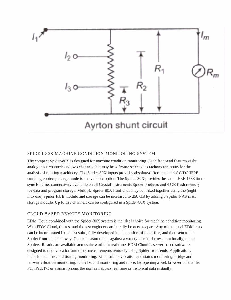
By Using Universal or Ayrton Shunt
The universal shunt or ayrton shunt is shown in figure is also used for multi range ammeters.
The advantage of this is that it climinates the possibilitiy of the meter being in the circuit
without shunt.
SPIDER-80X MACHINE CONDITION MONITORING SYSTEM
The compact Spider-80X is designed for machine condition monitoring. Each front-end features eight
analog input channels and two channels that may be software selected as tachometer inputs for the
analysis of rotating machinery. The Spider-80X inputs provides absolute/differential and AC/DC/IEPE
coupling choices; charge mode is an available option. The Spider-80X provides the same IEEE 1588 time
sync Ethernet connectivity available on all Crystal Instruments Spider products and 4 GB flash memory
for data and program storage. Multiple Spider-80X front-ends may be linked together using the (eight-
into-one) Spider-HUB module and storage can be increased to 250 GB by adding a Spider-NAS mass
storage module. Up to 128 channels can be configured in a Spider-80X system.
CLOUD BASED REMOTE MONITORING
EDM Cloud combined with the Spider-80X system is the ideal choice for machine condition monitoring.
With EDM Cloud, the test and the test engineer can literally be oceans apart. Any of the usual EDM tests
can be incorporated into a test suite, fully developed in the comfort of the office, and then sent to the
Spider front-ends far away. Check measurements against a variety of criteria; tests run locally, on the
Spiders. Results are available across the world, in real-time. EDM Cloud is server-based software
designed to take vibration and other measurements remotely using Spider front-ends. Applications
include machine conditioning monitoring, wind turbine vibration and status monitoring, bridge and
railway vibration monitoring, tunnel sound monitoring and more. By opening a web browser on a tablet
PC, iPad, PC or a smart phone, the user can access real time or historical data instantly.

SOFTWARE FEATURES
EDM Remote Monitoring Software
Automated Production Testing
PRODUCT SPECIFICATIONS:
Inputs: 8 BNC connectors per front-end, front-ends are networked to form up to 128 inputs, voltage or
IEPE, single-ended or differential, AC or DC coupling, 150 dBFS dynamic range, 24-bit A/D converters,
range ±20 volts, up to 102.4 kHz fs per channel
Outputs: 2 BNC connectors per front-end, 100 dB dynamic range, 24-bit A/D converters. ±10 volts
Channel Phase Match: Better than ±1.0 degree up to 20 kHz among all channels
Dimensions: 238.8 x 215.7 x 20 mm, four Spider-80X front-ends fit into one 1U 19 inch rack-mount slot
Weight: 1.3 kg per front-end
Power: Powered from external DC power
Computer Connections: 100Base-T, RJ45 female connector supports connection to PC or network
switch
Internal Memory: Flash memory for data storage is 4 GB per unit
Real Time Analysis Functions:Data recording, Math (+,-,*,/), integration ,differentiation, FFT, average,
window, auto power spectra, cross-spectra, FRF, coherence, real-time filters, RMS, swept sine, limiting,
alarm/abort and many more.
Operation Modes: Connected to computer or stand alone Black Box mode.
UNIT III ANALYTICAL MEASUREMENT
Measuring method
The E+E CO2 sensors feature the dual wavelength/dual detector NDIR principle. One detector is tuned to
4.2 µm wavelengths, which is absorbed by CO2, the second detector on 3.9 µm, which is not affected by
any gas. For every single measurement the CO2 concentration is calculated from the outputs of the two
detectors.
This procedure is highly insensitive to pollution and appropriate for both HVAC and demanding
applications.
A multiple point CO2 and temperature adjustment procedure leads to excellent CO2 measurement
accuracy over the entire temperature working range.
Several E+E CO2 measuring devices feature also temperature and humidity measurement.
Product range: HVAC transmitters

Transmitters for agriculture and other demanding applications
OEM modules and probes Data loggers
Hand-held instruments
Applications: Demand controlled ventilation
Indoor air quality
Stables
Incubators
Greenhouses
Industrial process control
For decades users in environmental and water analysis rely on TOC analyzers by Elementar. The whole
spectrum ranging from ultrapure water, waste water to sludges and solids is covered by a single flexible
TOC analyzer. In addition to the determination of TOC, the content of total bound nitrogen (TNb) can
also be determined simultaneously in aqueous samples. Even difficult samples like sea water and
concentrated chemicals and acids are no longer a challenge. The measuring range extends from a lower
detection limit of 3 µg/l (vario TOC cube) up to 100,000 mg/l (vario TOC select).
There is no need to mention that the analysis of water is performed fully automatically. But also solids
can be analyzed for TOC through automatic sample feeding. Just weigh the sample in tin capsules, seal
the capsule and put it on the sample tray - that‘s it. Even the change from liquid to solid mode can be
performed in max. 5 minutes. Analysis times of 3 to 4 minutes turn Elementar‘s TOC analyzers into work
horses for routine operation in environmental and water analysis.
Oxygen Analyzer SGM5
General Information
The compact high-precision oxygen analyzer SGM5T contains the approved calibration- and
drift-free ZIROX zirconia measuring cell as well the electronic unit (for cell heating control, flow
monitoring, cell signal processing, calculations and signal output, e.g. oxygen concentration, air factor ,
redox-quotient or H2O/H2-ratio). A microprocessor changes the cell signal to the oxygen concentration
according to the NERNST equation. The value is displayed as an analog current signal (option: digital
interface RS232, software for measuring value recording and storage is available). In addition, the
electronic unit can process and provide the signals of another, optionally integrable sensor (e.g. CO2-,
humidity- or pressure sensor with standard interface).
The oxygen analyzer SGM5S was especially developed for measurements in CO2-atmosphere of
breweries. It contains additional parts for gas filtering and pressure reduction.
In the SGM5, the measuring cell is continuously monitored. In case of an error, an
alarm signal is generated.

Applications
In many technological processes under protective or inert gases, oxygen traces are disadvantageous for
the product properties. Precondition for detection and prevention of problems is the fast and precise
measurement of oxygen and the determination of the reducing force of inert gases respectively. Due to the
increasing adoption of a quality management system (e.g. ISO 9000), a constant monitoring and
documentation of quality parameters becomes more important. The SGM5 provides various options for
process optimization (soldering and welding processes, heat treatment of metallic surfaces,
microelectronic production, food packing technology). For the monitoring of reducing gases, further
parameters (redox-quotient, air factor λ, H2O/H2-ratio or CO2/CO-ratio) can be calculated by special
mathematical methods.
Blast air burner
The blast air burners can be divided
into the electromechanical integration type and split type according to different structures of the burner.
The series of burners are composed of multiple internal-mixed inside nozzle,external-mixed nozzle and
air distribution duct. In order to realize complete combustion and facilitate adjustment, the air shall be
divided into two parts to enter into the burner during combustion(the primary air and secondary air). The
flame shape and combustion conditions shall be adjusted by adjusting the primary air and secondary air
flow and air speed, to realize stable and complete combustion. It can be applicable for the high-
pressure,medium-pressure and low-pressure fuel gas and the product has been obtained the National
Patent with the patent number ZL00200606.5.
Feature 1. The burners are compact structure,artistic appearance and convenient installation.

2. The method of combining the internal-mixed multipleheads and external-mixed multiheads are applied,
to realize safe,stable and high-efficient combustion.
3. The designed pressure of the natural gas is 8-10KPa usually and it can also be designed according to
the actual working conditions of the user.
4. Wide power adjustment range:30% to 110%.
5. The flame dimensions can be designed according to user‘s requirements.
6. The different forms of automatic control can be configured: type (air door sectioned control and
frequency conversion sectioned control), air door adjusting proportion type and frequency conversion
adjusting proportion type, touch screen digital control, industrial computer frequency conversion
proportion control and so on. It can meet different user's requirements.
7. The fuel gas and the air door shall be controlled by the separate channel, the air / gas proportion K
value shall be set online to accurately control the air / gas proportion and prevent error caused by
connecting rod transmission.
8. The system shall be equiped with flame detection, over-temperature, overpressure, leakage detection in
valve groups and other safety interlock protection.
9. If the self-control system is removed, normal combustion can be conducted with manual operation,
which is easy to adjust.
Introduction of the model
Technical performance Figure

Non-blast burner
The non-blast burners can be divided into the non-blast burner and non-blast / blast burner according to
different forms of the air distribution. The burners adopts the new design idea, which combine the
traditional combustion process( the single internal mixed and the external mixed combustion), forming a
new type of internal and external mixed combined non-blast fuel gas burner. The non-blast / blast burner
is also the new burner which combine the non-blast combustion technology and blast combustion
technology. The s burners have been obtained the National Utility Model Patent with the patent number
ZL94248195.X.
Till now, more than 500 sets of non-blast burners have been applied in the Jidong, Daqing, Liaohe,
Dagang, Shengli, Zhongyuan, Henan, Changsheng oilfield, which stable performance, convenient
operation, creating the high economic and security benefits.
Performance characteristics
1,The non-blast combustion technology is applied in the large negative pressure fuel gas furnace, heating
furnace and industrial furnace. The single burner can be non-blast high-efficient combustion in the fuel
gas negative pressure furnace with less than 20t/h (14MW or 1200*104kcal/h).

2,It can be realized that the stable and high-efficient combustion within the designed scope of 30% to
110% output, meeting requirements for the ulimate load.
3,Local control. It can be electricity-free self-control. With simple operation, it is applicable for outdoor
operation.
4,The non-blast / blast burner can be operation with or without blast. It is wide scope of application.
5,The blast air is forced to work before the igniton in the non-blast / blast burner, to guarantee safe
ignition. After the ignition is Ok and the main fire is established, the fan is stopped automatically. The air
and the gas can be automatic matched by utilizing the fuel gas pressure and the negative pressure of the
furnace chamber. So that the safe and high-efficient combustion is guaranteed and the ulimate energy-
saving effect is reached.
6,According to the user's requirements, the fire-off protection, automatic ignition control, automatic
adjustment and the interlock control system required for operation can be configured with stable
performance.
7,In addition to the natural gas, the burners shall also be applicable for the semi-water gas, coke oven gas,
gas and so on. The designed pressure shall be 20-50kpa.
Introduction of the model
Technical performance Figure

UNIT IV CONTROL LOOPS IN BOILERS
sat-nms MNC Monitoring & Control System
SatService´s Monitoring & Control System sat-nms MNC is a comprehensive software-based system
providing monitoring and control of any type of satellite ground station and associated baseband
equipment.
The system consists of two parts:
2RU 19" Industrial PC with Ethernet interface and serial interfaces connected to the ground
station equipment

sat-nms IO-FEP parallel interface for low level devices like alarm contacts or waveguide/coxial
switches.
The sat-nms MNC Software is seperated into two in Java implemented modules: sat-nms MNC Server
and Client. Both modules are installed on the industrial PC and running under the Linux operating
system. The platform-indepented client software can also run on every TCP/IP connected workstation.
Features
Client Server Software Architecture
TCP/IP-based Design
Server operating under LINUX with full remote Administration and Support Capability
Clients are operating independent from System
Unlimited Number of Clients possible
Event/Alarm Log with a lot of Filter Utilities
Task- and device-oriented User Interfaces
Macro Recording Functionality
Software configurable Interface Device Configuration
Integrated graphical Tool for User Interface Configuration
Comparable Equipment of different Manufacturers has the same "look and feel"
Applications
VSAT-Hub
SNG, SNG Central Station
TV-Uplink
Teleport
Hardware
2RU 19" rack-mount Industrial PC
LAN (TCP/IP) Interface
Power Supply Wide Range Input Voltage 90V to 240V 50/60Hz AC
CD- and ZIP-Drive for Backup Capability
Rack-mountable 15" TFT Monitor, Keyboard and Trackball for local Control
Interfaces to Satcom Equipment
The sat-nms MNC is able to monitor and control the attached equipment via the following types of
interfaces:
Serial RS232 Interface
Serial RS422/RS485 Interface
Network Interface (Ethernet,TCP/IP)
SNMP Interface via Network

Parallel Interface for low level Devices like Alarm Contacts or waveguide/coaxial Switches via
the sat-nms IO-FEP
sat-nms MNC-Server
The sat-nms MNC Server monitors and controls the equipment of a satellite ground station. The
monitoring is performed locally without any influence and connection by any operator client. The
connected equipment is polled and monitored continuously. Typical alarm flags of the equipment, like
summary alarm, lock alarm, etc., thresholds or limits of data quality are detected. The alarm message is
stored in the internal sat-nms MNC database at the sat-nms MNC Server and the client operator is alerted
via both a graphical and an audible alarm.
Virtual Device Driver defines families of satellite ground station equipment with common user interfaces
for operator with multi vendor equipment in the field, e.g. all satellite modems are presented to the
operator in the same look and feel. This simplifies the handling because device specific details are hidden
from the operator.
Logical Devices are also available like EIRP Adjustment, Data Logging (any parameter that is displayed
can be logged to file), Redundancy Switching and Site Diversity Switching.
sat-nms Drivers
The Universal Device Driver concept reduces the cost for the configuration of new drivers. The user can
configure its own drivers without writing software. Parallel to that SatService will always provide the
service to adapt new equipment with drivers to the system. Drivers are always the same for sat-
nms MNC- and VLC-Systems.
The Driver Development Kit (sat-nms DDK), which is an eclipse-platform-based Integrated Development
Environment supports the user to configure and test new drivers and protocols. For details please
see datasheet.
Device Licenses, Configuration Changes and Upgrades
The basic sat-nms MNC-0/0 System already contains 5 device licenses that can be used, e.g. for devices
connected via TCP/IP. Additionally, each sat-nms MNC System Package contains device licenses for
every serial interface that is included e.g. the sat-nms MNC-4/8 System contains 5+4+8=17 licenses to
monitor and control 17 units.
With the included configuration tools for the interface setup and the graphical user interface our customer
is able to add, remove or change the connected equipment. Our customer is also able to add new types of
devices from the sat-nmsDriver Library or even configure new drivers by himself.
This flexible approach provides you with all possibilities to use our sat-nms MNC System even with
changed conditions in the future. Upgrade kits to extend the number of available interfaces are also
available.

sat-nms MNC-Client
The client software is the user interface for the operator of the ground station. The operator accesses
the sat-nms MNC System directly via the sat-nms MNC Industrial PC or via an arbitrary workstation in
the network connected via TCP/IP. The number of clients is not limited.
The platform independend Java software requires only a Java virtual machine on the Client-PC. We have
tested the software successfully on Windows 9x/NT4/W2K/XP/7/8 and of course on Linux PCs.
With the purchase of the sat-nms MNC System you obtain the licenses for an unlimited number of clients
so that you do not have additional costs.
There are two kinds of user interfaces available:
device-oriented user interface
task-oriented user interface
The device-oriented user interface provides all parameters of the satellite ground station equipment and
gives a deep insight in the equipment for system engineers. It is part of the delivery and shows every
attached device in a block diagram view. The device-oriented screen will be mostly used in stations with a
static configuration for monitoring & control and redundancy switching.
The task-oriented user interface is a customized user interface, fully configurable and reduces the user
interface to the special requirements of the operators. Several task-oriented and or device-oriented user
interfaces can be used in parallel. SatService will be glad to offer you the configuration regarding your
needs, but you are also able to do this on your own with the integrated graphical screen editor.
Remote Access
The sat-nms MNC Server is completely configurable and maintainable remotely. These actions only
require a TCP/IP connection and for the clients only a TCP/IP connection to the sat-nms MNC Server.
This can be an already existing network (LAN) or a dialup connection (e.g. PPP).
SatService offers also ISDN and VPN solutions to connect different locations on request. Via these
routers SatService can give you remote support if you need it.
UNIT V NUCLEAR POWER PLANT INSTRUMENTATION
I N T R O D U C T I O N
The Instrumentation and Control (I&C) of a nuclear power plant (NPP) are the eyes and ears of the
operator. If properly planned, designed, constructed and maintained they will present him with correct,
appropriate information that will enable him to take judicious action during abnormal operations. They
thus form, along with the human operator, the most vital link for the safe, efficient operation of a plant.
Under normal operating conditions, the I&C systems steer the plant for the operator, allowing him time to
observe the overall behaviour of the plant, perform calculations and operations of an ancillary nature, etc.,
at the same time presenting the operator with all the necessary relevant information at his finger tips,
allowing him — so to speak - constantly to monitor the pulse of his plant so that he is poised to take
corrective action when required. Despite the importance of I&C to safe, efficient plant operation, it plays
a very small role in the selection of a reactor type or a nuclear steam supply system (NSSS) vendor. This
can be governed by many other considerations. The I&C specialist may therefore find that he may have
little to say in plant selection, though later on — during commissioning and operation — what was
selected may greatly affect his work as well as plant operation. The I&C specialists may also find that
during the planning and pre-project phases, the activities such as I&C manpower and organizational
planning will take a second place to fuel economics, siting, etc. This situation need not be accepted
passively. I&C personnel can and should — right from the beginning — develop an appreciation and
knowledge of the equipment and systems and determine whether stated objectives for safe, efficient
operation of the plant will be met by the equipment proposed to be supplied. They can also determine
whether adequate measures are included in the national programme as well as in the contract agreement
with vendors for the requisite transfer of technology that will enable I&C personnel to support the plant
during its lifetime. One purpose of this guidebook is to present the I&C specialists with various
considerations and implications so that they can prepare themselves and proffer to their management
cogent reasons and measures for I&C planning and organization right from the very inception of the
project. Since it takes a minimum of six to seven years from signing of the contract to commercial
operation, this lead time is quite adequate for preparing the I&C personnel for the responsibility of the
operation and maintenance of I&C equipment and systems, provided that recruitment and training is
started from the planning phase. One fact that may already be apparent to the reader is that the I&C
specialists — more than any other NPP specialists — have to be versatile, as their work is interactive with
many areas outside their discipline: with 3 the operation of the plant, with process systems, with health
physics and radiation monitoring, and of course with safety. There is a need for the I&C specialist not to
confine his learning to I&C equipment and systems only. He should be equally familiar with operating
procedures, plant dynamics, and process systems as with I&C systems. This broad base of knowledge will

greatly ease his job, and will assist him in communicating with non-I&C personnel in their language
rather than in the specialized jargon which tends to be used by computer and I&C personnel. I&C
personnel will find that they have to interpret plant transients or faults (such as a sudden spike in coolant
pressure or power output) in terms of specific control equipment behaviour (be it genuine or a result of
equipment malfunction). A knowledge of process systems and their operation is therefore invaluable. The
I&C personnel for a country‘s first nuclear power plant may be drawn either from nuclear research
centres, from process industries (refineries, etc.) or from fossil-fuelled power plants. It may be worth
while pointing out some of the special I&C requirements of a nuclear power plant and the spheres of
activity of an I&C organization. The instrumentation and control requirements of a nuclear power plant
are far more complex and diverse in nature than those of a conventional plant. There are several reasons
for this, some of which are: (1) The availability of a nuclear power plant is of much greater concern than
that of a conventional station because of the nuclear plant‘s higher capital cost. The plant availability is
totally dependent on the reliable measurement of plant parameters and their control. (2) Due to non-
accessibility of the reactor during plant operation, the state of the reactor and associated systems is
required to be displayed in, and manipulated from, a central control room. (3) Highly reliable redundant
safety systems are required to ensure the automatic safe shutdown of the plant to prevent damage to the
equipment and personnel. (4) Since reactors and their instrumentation are experiencing rapid
technological advances, the I&C of these systems are being regularly updated. New systems and
equipment are being introduced as a result of obsolescence caused by these technological advances, and
to provide improved performance and safety. The following needs are therefore important while planning
for I&C support: (1) Engineers and technicians familiar with the conventional process instrumentation
and/or with instrumentation of a research reactor. (2) Engineers and technicians specifically trained in the
I&C of the nuclear power plant being acquired. 4 (3) Training facilities for providing an understanding of
the I&C of a nuclear power plant and imparting skills for repair and maintenance of I&C equipment. (4)
Design knowledge for reviewing, and where necessary, upgrading the performance of I&C equipment and
systems. This is essential for modification of systems that do not meet the design intent and safety
requirements and for subsequently combating obsolescence in I&C equipment. (5) Facilities for carrying
out periodic in-service inspection of plant equipment. (6) Ability to carry out major repairs to I&C
equipment speedily and effectively without jeopardizing the availability and safety of plant equipment.
(7) Ready availability of spares for the repair and maintenance of I&C equipment throughout the life of
the plant and avoidance of loss of production because of lack of availability of spares. (8) Monitoring the
performance of the safety systems. (9) Capability of generating better specifications for succeeding plants
based on experimental data and performance figures of the first plant. This section of the guidebook
attempts to highlight some of the problems encountered in each phase of a NPP project — and presents
possible remedies. Although the problems may be of common nature in many non-vendor, developing
countries, the solutions proposed are by no means universal. The Guidebook may however assist the
countries in problem identification and provide guidelines for solutions. 2. ORGANIZATION AND
METHODS The I&C is only a part of the overall nuclear project framework that will have to be
established at national as well as at owner/utility level. It is necessary to understand the various
organizational structures and interrelationships that are possible, and how and where I&C activities fit
into this overall scheme. For a detailed treatment of this subject, the reader is referred to IAEA Code of
Practice 50-C-G on Governmental Organization for the Regulation of Nuclear Power Plants (1978), and
TRS 200 — Manpower Development for. Nuclear Power: a Guidebook — and references therein. I&C
specialists will be required in each organization participating in the project and methods will need to be

established in this phase to enable I&C specialists to communicate and even to be shared, and to ensure
that rigid boundaries between these organizations are not set up. One suggestion is to establish technical
committees based on the various specializations required for a nuclear power programme, e.g. an I&C
Technical Committee could be 5 comprised of I&C specialists from all the above organizations. The
problem of communication may not be acute in an early stage of project development with only a few
people, but later on it can be a major hindrance if there is a lack of proper and timely planning. 2.1. I&C
for the Safety Regulatory Authority Once a government takes a decision to embark on nuclear power,
specific programme-oriented activities can be started. Among the most important of these is the nuclear
safety regulatory activity and the establishment of a Nuclear Safety Regulatory Authority. An I&C
Technical Committee comprising I&C specialists working in various organizations could serve as the
technical arm of the regulatory body to assist it during the early stages where it may not have the
necessary technical expertise itself. Consultants from the IAEA or from a country other than the one
supplying the nuclear power plant would be especially valuable and necessary for the regulatory body. In
an early phase the work of the regulatory I&C staff may include: (1) Getting thoroughly familiar with the
various I&C standards, such as the Institute of Electrical and Electronics Engineers (IEEE) standards for
reactor protection, International Electrotechnical Commission (IEC) and IAEA safety guides and the
general design criteria of some of the major NSSS vendors and their application to their reference plants.
(2) Getting familiar with reliability techniques, fault-tree analysis failure modes and effects, etc., and with
the available computer codes. (3) Dissemination of information, either compiled initially or later
internally generated studies and analyses, on design features and operational experience of nuclear power
plants. 2.2. Nuclear licensing and regulation Whereas there could be considerable I&C expertise available
in a country embarking on a nuclear power programme, on the other hand, with a country‘s first nuclear
power project, there may be a total lack of experience in nuclearsafety-related I&C activities. The
following is recommended as prerequisite reading for all I&C professionals, especially those involved in
nuclear safety regulatory activities: (1) IAEA Safety Guides, specifically 50-SG-D3: Protection System
and Related Features in Nuclear Power Plants 50-SG-D8: Safety-Related Instrumentation and Control
Systems for Nuclear Power Plants 6 (2) Nuclear IEEE Standards (in 2 volumes) (3) Material1 from the
IAEA training course on nuclear power safety analysis review, held at the Argonne Centre for
Educational Affairs in 1978. The work of an I&C specialist on safety regulatory activities falls into the
following categories: Codes and standards Adoption and adaptation of codes and standards of the IAEA
and/or the vendor country to the nuclear power plant being built specifically, and generally for the nuclear
power programme. Interpreting and clarifying these to the owner/utility using specific examples from the
nuclear power plant being built. In addition to IAEA Codes of Practice and Safety Guides, of interest to
the regulatory I&C specialists are the IEEE and IEC standards and relevant sections of the ASME guides
which specify the penetrations and fittings required for transducers such as resistance temperature
detectors (RTDs), etc., within the reactor pressure boundary. A detailed list of these standards and guides
is contained in the bibliography. Licensing and safety assessment Ii The work starts in 'the pre-project
phase with discussions with vendors on the safety aspects of their proposed NSSS types, and explaining
to them the specific national requirements. Subsequently I&C specialists participate in the preparation or
review of the bid specifications and later in the evaluation of the bids from the safety; point of view. Once
the contract is signed and the design work starts, participation in the design review process at the design
offices of the main supplier can provide extremely valuable knowledge not only of the plant being
constructed but also of the various methodologies of the design review process, and knowledge of the
process system parameters and design. This will assist verifying that the design conforms to the

applicable criteria and codes. The I&C specialists in this area of activity will be responsible for reviewing
the safety analysis reports and the assessment of applications for construction permits, operating
licenfces, etc. During commercial operation, the I&C specialists would be responsible for reviewing
performance reports of the safety systems and of other I&C systems and ensuring that the integrity of the
systems as designed is being maintained. They would also review and give approval to any design
changes or modifications. 1 For example, the lectures by YAREMY, E. on ― Introduction to Review of
I&C Systems‖ and SCHOLL, R.F., Jr. on ― Reactor Trip Systems‖ . 7 Inspection and enforcement These
activities ensure the enforcement of standards, rules and regulations, and include investigations of unusual
occurrences or any suspected breach of regulations, etc. Development work and dissemination of
information The dilemma of I&C specialists working in nuclear regulatory activities in a country
embarking on its first nuclear power plant is that they have to review and adjudge activities in which they
play no participating role, and thus have little opportunity for gaining experience by actually doing things
like their counterparts in the utility and the project design engineering group. Furthermore, they may find
no technical support within the country, i.e. from independent specialists, consultants or advisory bodies,
to advise and assist them. A clear definition of their authority by the highest management level and by
national legislation is vital, and will assist the I&C specialists in obtaining the required information and
acceptance by the owner/utility. This definition of their authority will result in the owner/utility being
required to involve the nuclear regulatory personnel at the appropriate times and also explain and clarify
to them the reasons for the various decisions and courses of action taken by the owner/utility. This will
enable a learning process and a growing in maturity of the I&C safety personnel. The exercise of
authority vested in the regulatory body may bring about compliance and obedience from the owner/utility
but will not solve the problem of gaining respect by virtue of superior technical expertise. It is therefore
recommended that the image of the I&C specialists of the regulatory authority (and even of the Safety
Division of the plant) as ‗inspectors‘ and ‗enforcers‘ be tempered with the role of disseminators of
information and as sources of advice. Starting from the project preparation phase, the I&C personnel of
the Regulatory Authority could also perform the following work which would enhance their knowledge
and also assist the owner/utility: — preparation of explanatory notes with specific examples of how the
codes, standards and design criteria are to be applied to the evaluation of the I&C of the plant systems; -
carrying out analysis and design review studies of the operating power plant; — developing simplified
models and computer programs to analyse and illustrate the dynamics of overall plant control and the
major control systems; - collating, analysing and disseminating information pertaining to experience in
the design and operation of nuclear power plants. 8 The various organizational and work considerations of
nuclear licensing and regulation are discussed below: Advisory services and consultants I The advisory
services of an independent agency such as the IAEA can prove invaluable in establishing the programme
of the regulatory body and in complementing the regulatory authority personnel by specialists in various
disciplines. ii Adoption of proven standards and codes A basis for the safety assessment and licensing of
I&C systems must be established in the form of a set of safety criteria, guides and rules. In a country
embarking on a nuclear power programme usually the base of related engineering standards is narrow and
nuclear standards are lacking completely. It is usual therefore to adopt another country‘s regulatory
framework, in most cases that of the main supplier. This tends to save costs because the supplier can use
standards familiar to him. A global adoption, however, can create problems: differencesjn the state of
development of the exporting and the importing country have to be taken into account. Local conditions
and characteristics have to be given proper consideration .in order to avoid misuse or misunderstanding of
adopted standards or codes. Differences in application can arise from varying interpretation of how

certain criteria may be satisfied. In other cases requirements may not be applicable at all (e.g. historical
seismic data). Applying a given set of rules also requires a certain amount of supporting software, such as
computer programs, data banks, etc., to enable verification of vendor calculations and data. I
Development of national codes and standards ■ A country initiating a nuclear power programme may not
have the experience to develop and codify a complete set of nuclear codes and guides of its own. In fact,
even countries having extensive experience in safety practices have not documented in all cases their
experience in a form suitable for general use. To provide a frameiof reference for the government, the
regulatory body ii and other relevant organizations of Member States, the IAEA has been preparing a set
of Codes of Practice and Safety Guides. These codes and guides are based on current practices and
recommendations. They establish general recommendations and minimum requirements. They 9 do not
contain, however, specific standards for design or maintenance of equipment. If a country wishes to use
them as part of its own national regulations, this can be achieved by transferring them fully or partly into
national codes or guides. Another way of adjusting regulations to the specific needs of a country is to
modify existing codes or their range of application. Difficulties encountered in combining different codes
and standards Care must be taken in simultaneously using existing codes and standards of different origin
as a basis for review work. Using various guides and combining them to form an ‗envelope‘ does not
necessarily make an optimum safety frame of reference. Avoiding licensing delays The following may
lead to delays in licensing: (a) A licensing aspect is not considered from the beginning of the licensing
process, e.g. — fire protection — building construction (separation, plant layout) — air crash —
meteorological aspects — earthquake — flood — new industry (explosion danger, air pollution with
aggressive effluents) — man-induced accidents (b) The regulatory body obtains knowledge of aspects
relevant to safety too late and therefore some quality postulations and need for certificates may arise after
a certain component has already been manufactured (c) The material given to the licensing staff needs too
much investigation before licensing (d) The communication possibilities between licensing staff, safety
assessors, vendor‘s and operator‘s personnel are too inefficient (distance, no permission for direct
communication, no readiness for direct conferences, language problems) (e) Too many of those
examinations, tests and investigations which are possible during the construction phase are postponed
until later. Another significant reason for prolongation of the project is re-interpretation of regulatory
criteria, after the project has started, such as those relating to seismic protection, fire protection, missile
protection, plant security, etc. 10 Changes and additions, especially during the later stages of construction
add extremely to costs and to construction time. Such changes may have a much more significant side-
effect on I&C than is apparent at first. Fire barriers, seismic reinforcements, additional equipment
redundancies required, etc., affect not only the systems in question but also power supplies,
instrumentation, ventilation, cable raceways, additional penetrations of barriers, etc. Careful, timely
consideration of the above points can prevent expensive delays arising from the licensing process. 3.
TECHNOLOGY TRANSFER AND NATIONAL PARTICIPATION I Instrumentation and Control is
one area of the nuclear power plant where national participation can produce substantial benefits not only
for the power plant but for the country as a whole. Instrumentation and Control of a current nuclear power
plant is heavily biased towards electronics (very few pneumatic controls are used, other than for the final
control elements, i.e. control valves, etc.) and electronics is aHvery fast-changing technology with a built-
in obsolescence factor that is a cause of grave concern for a developing country installing its first nuclear
power plant. It expects its instrumentation to last for the lifetime of a plant. ; Simplifying somewhat, one
may define I&C obsolescence in this context as lack of the support necessary to keep I&C equipment and
systems operational. If an instrument recorder cannot be repaired because parts of it are no longer

available or/and the manufacturer is not making this type of recorder any more or has gone out of
business, this installed recorder (though it may still be functional) has to be considered obsolete because
support for it is unavailable. The factors behind this lack of support, i.e. technological improvements that
may have allowed bigger, better and cheaper recorders to be made, can be regarded as irrelevant for the
owner of the recorder who has already paid for his recorder and is happy with its capability if only he can
keep it running. Thus, if the I&C technological and industrial infrastructure can be geared towards
support for theil&C of the plant, i.e. parts, services, components and functional substitution design
capability are available within the country, the problem of obsolescence may not arise, a problem which
may otherwise result in costly and expensive imported replacement equipment plus plant down-time. The
following text, and the data in Table I are reproduced from the IAEA Guidebook
―Manpower.Development for Nuclear Power‖ (page 216 ff.). ―Items such as instrumentation have high
technical difficulties combined with relatively low cost;1 These, however, involve a high technological
content and might have important spin-off effects on the overall industrial development of the country.
Therefore special efforts for national participation might be justified.
Radiation monitoring
Radiation Detectors and X-Ray Measurement
Radiation safety quality assurance is top of mind for hospitals, nuclear power facilities, nuclear medicine
laboratories, x-ray manufacturers, government agencies, state inspectors, emergency response and
HAZMAT teams, and police and fire departments around the world. Fluke Biomedical offers a complete
line of radiation detection and safety products and solutions that allow these professionals the versatility
they need to get the job done and the quality they trust in a radiation-safety device.
Start the conversation »
451P Pressurized μR Ion Chamber Radiation Survey Meter
The auto-ranging 451P features a pressurized ion chamber, providing enhanced sensitivity (µR resolution)
and improved energy response to measure radiation rate and dose from x-ray and gamma sources.

Well-suited for a wide range of end users, including: x-ray manufacturers, government agencies,
state inspectors, biomedical technicians, and maintenance technicians for airport baggage
scanners
A fast response time to radiation from leakage, scatter beams and pinholes
The low noise chamber bias supply provides for fast background settling time
451B Ion Chamber Survey Meter with Beta Slide
The auto-ranging 451B measures radiation rate and accumulated dose from beta, gamma and x-ray
radiation sources.
Well-suited for a wide range of end users, including: police and fire departments, x-ray
manufacturers, government agencies, state inspectors, emergency response and HAZMAT teams,
nuclear medicine labs, hospital radiation safety officers, and nuclear power workers
A fast response time to radiation from leakage, scatter beams and pinholes
Victoreen® ASM-990 Advanced Survey Meter

The Victoreen® ASM-990 series can detect alpha, beta, gamma, or x-ray radiation within an operating
range of 1 µR/hr to 1 R/hr (1 to 5,000,000 CPM), depending on the selected probe (Geiger-Mueller,
neutron, proportional counter, scintillation). With the proper probe combination, this meter can be used
as:
A general survey meter
An area monitor
A wipe test counter
A contamination monitor
Check out our state of art X-ray quality assurance solution - RaySafe X2!
The RaySafe X2 is our flagship for radiology and fluoroscopic x-ray test and measurement. The X2
combines advanced sensor technology with a completely new user interface, plus we‘ve added a new
survey sensor that completes the set. Features of the RaySafe X2 system include:
Covers all x-ray modalities and offers sensors for R/F, MAM, CT, Survey, and even light
applications
Large touch screen display for great overview of measured parameters and waveforms
No selections, just connect and measure
Small size sensor with stacked diodes for easy positioning
Built-in-memory storing all measurements and waveforms in the base unit
Wide dynamic range for all types of measurements