UNIT -1 DESIGN OF FIELD SYSTEM AND ARMATURE PART-A
59
UNIT -1 DESIGN OF FIELD SYSTEM AND ARMATURE PART-A 1. Define specific electric loading [NOV/DEC2016,NOV/DEC2017,NOV/DEC2019] It is defined as the ratio of total number of ampere conductors and the armature periphery at the air gap. 2. What are the factors that affect the size of rotating machine?[Nov/Dec 2016] Speed, output, coefficient, specific electric loading, specific magnetic loading. 3. Write down the classification of magnetic materials [MAY/JUNE 2015] (i) Soft magnetic materials (ii) Hard magnetic materials (or) (i)Ferro magnetic materials (ii)Paramagnetic materials (iii)Diamagnetic materials 4. What are the major considerations in electrical machine design [MAY/JUNE 2013] The major considerations to achieve a good electrical machine are specific electric loading, specific magnetic loading, temperature rise, efficiency, length of wire gap and power factor. 5. Define gap contraction factor for slots[NOV/DEC 2014] It is defined as the ration of reluctance of air gap of slotted armature to reluctance of air gap of smooth armature. 6. What is peripheral speed? Write the expression for peripheral speed of rotating machine [NOV/DEC 2013] The peripheral speed is a translational speed that may exist at the surface of the factor, while it is rotating. (Translational speed equivalent to the angular speed at the surface of the ratio) z z I ac D
Transcript of UNIT -1 DESIGN OF FIELD SYSTEM AND ARMATURE PART-A

UNIT -1
DESIGN OF FIELD SYSTEM AND ARMATURE
PART-A
1. Define specific electric loading [NOV/DEC2016,NOV/DEC2017,NOV/DEC2019]
It is defined as the ratio of total number of ampere conductors and the armature periphery at the
air gap.
2. What are the factors that affect the size of rotating machine?[Nov/Dec 2016]
Speed, output, coefficient, specific electric loading, specific magnetic loading.
3. Write down the classification of magnetic materials [MAY/JUNE 2015]
(i) Soft magnetic materials
(ii) Hard magnetic materials
(or)
(i)Ferro magnetic materials
(ii)Paramagnetic materials
(iii)Diamagnetic materials
4. What are the major considerations in electrical machine design [MAY/JUNE 2013]
The major considerations to achieve a good electrical machine are specific electric loading,
specific magnetic loading, temperature rise, efficiency, length of wire gap and power factor.
5. Define gap contraction factor for slots[NOV/DEC 2014]
It is defined as the ration of reluctance of air gap of slotted armature to reluctance of air gap of
smooth armature.
6. What is peripheral speed? Write the expression for peripheral speed of rotating machine
[NOV/DEC 2013]
The peripheral speed is a translational speed that may exist at the surface of the factor, while it is
rotating.
(Translational speed equivalent to the angular speed at the surface of the ratio)
z
zIac
D
Va = Dn m/sec
D = diameter of rotar in m
N = speed of rotar in rps.
7. List the Indian Standard Specifications for a transformer [NOV/DEC2017]
IS 2026-1972: Specifications of power transformer.
8. List the Indian Standard Specifications for induction motor.
IS 325 – 1966
IS 1231 – 1974
IS 4029 – 1967
IS 996 – 1979
9. Give the expression for total Electric loading and total magnetic loading.
Total magnetic loading = P
Total Electric loading = Izz
10. What is super conductivity? List few of the materials and compounds that exhibits the
property of super conductivity.
The state of material in which it has zero resistivity is called super conductivity. The super
conductivity is obtained when temperature is brought down below the transition temperature.
The super conductivity materials are mercury, metals and alloys.
11. Define heating time constant.
The heating time constant of a machine is the index of time taken by the machine to attain its
final steady temperature rise.
tn =
Gh
S secs
12. Define cooling time constant.
The cooling time constant is defined as the time taken by the machine for its temperature rise fall
to 0.368 of its initial value.
tc =
Gh
S
13. Distinguish between continuous rating and short time rating of an electrical machine.
Continuous rating :- The output of machine is obtained continuously without exceeding the
permissible temperature rise. The machines are permitted to overload upto 20% more than the
specified rating.
Short time rating :- It is the output which a machine can deliver for a specified period and
remaining duration in off position for a long to reach its cold conditions.
14. What are the major considerations to evolve a good design of electrical machine.
[NOV/DEC2011]
(i) Cost
(ii) Durability
(iii) Small size and less weight
(iv) Wider temperature operating limits
15. Define space factor
It is defined as the ratio copper (or) conductor area to the total winding
Sf =
( )copper or conductorarea
totalwindingarea
16. Define Short time rating.[NOV/DEC2017]
It is the output which a machine can deliver for a specified period and remaining duration in off
position for a long to reach its cold conditions.
17. What are the different conducting materials used in rotating machines?[NOV/DEC2018]
Copper, Aluminium,Iron and Steel, Alloys of copper.
18. Mention the various duty cycles of motor.[NOV/DEC2018]
(i) Continuous duty.
(ii) Short time duty.
(iii) Intermittent periodic duty.

(iv) Intermittent periodic duty with starting.
(v) Intermittent periodic duty with starting and braking.
(vi) Continuous duty with periodic duty.
(vii) Continuous duty with starting and braking.
(viii) Continuous duty with speed changes.
19. Define specific and magnetic loading.[NOV/DEC2017]
Specific electric loading:
It is defined as the ratio of total number of ampere conductors and the armature periphery at the
air gap.
Specific magnetic loading:
The average flux density over the air gap of a machine is known as specific magnetic loading.
Bav = Total flux around the air gap
Area of flux path of the air gap
20. What are the causes of failure of insulation?[NOV/DEC2019]
The losses produced in the machine are converted in to heat energy, as a result of which various
parts of the machine are heated .i.e. losses are produced mainly in iron parts of the machine
which carry flux and conductor which carry current resulting in increase in temperature of iron
and copper leads to insulation failure.
21. What are the factors that decide the choice of specific magnetic loading?[NOV/DEC2019]
(i) Maximum flux density in the iron parts.
(ii) Magnetizing current.
(iii) Core losses or iron losses.
PART – B
z
zIac
D
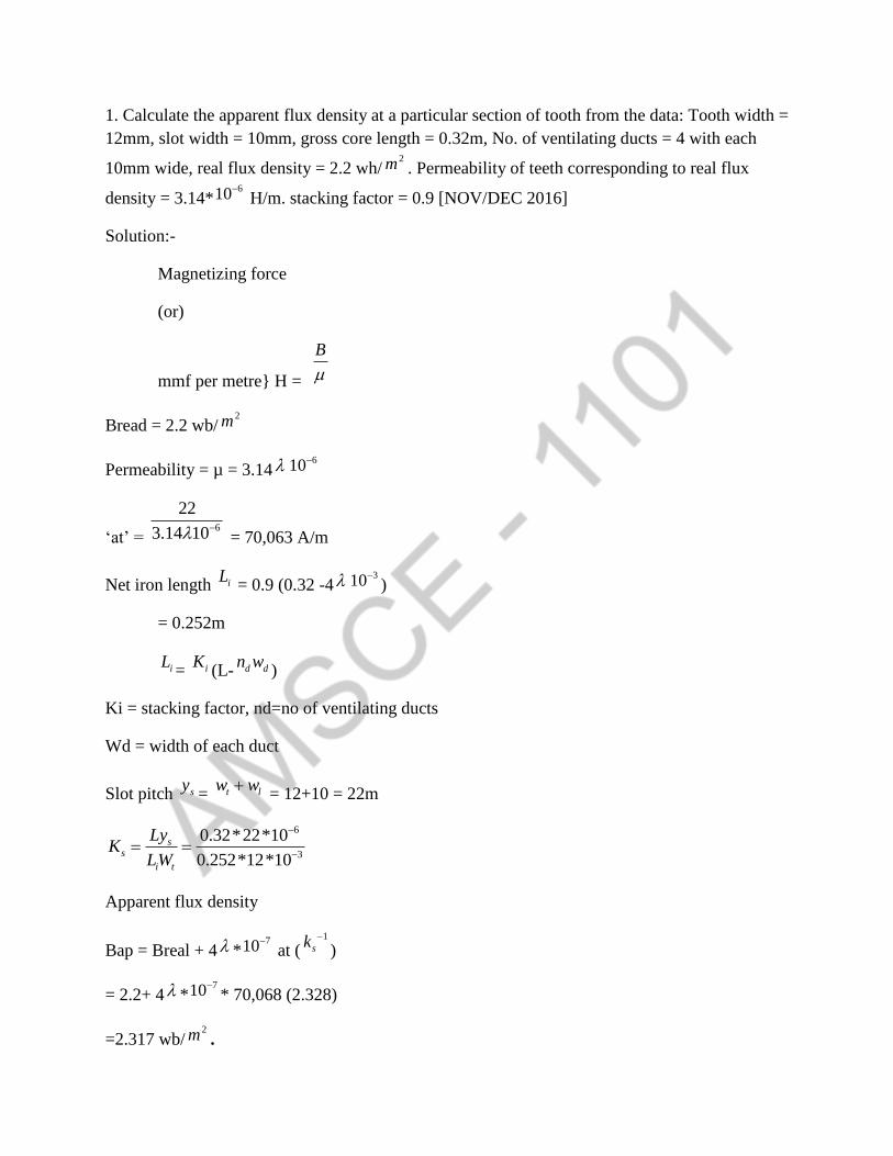
1. Calculate the apparent flux density at a particular section of tooth from the data: Tooth width =
12mm, slot width = 10mm, gross core length = 0.32m, No. of ventilating ducts = 4 with each
10mm wide, real flux density = 2.2 wh/2m . Permeability of teeth corresponding to real flux
density = 3.14*610
H/m. stacking factor = 0.9 [NOV/DEC 2016]
Solution:-
Magnetizing force
(or)
mmf per metre} H =
B
Bread = 2.2 wb/2m
Permeability = µ = 3.14610
‘at’ = 6
22
3.14 10
= 70,063 A/m
Net iron length iL = 0.9 (0.32 -4
310
)
= 0.252m
iL= iK
(L- d dn w)
Ki = stacking factor, nd=no of ventilating ducts
Wd = width of each duct
Slot pitch sy= t lw w
= 12+10 = 22m
6
3
0.32*22*10
0.252*12*10
ss
i t
LyK
LW
Apparent flux density
Bap = Breal + 4 *710
at (1
sk
)
= 2.2+ 4 *710
* 70,068 (2.328)
=2.317 wb/2m .

2. Calculate the mmf required for the airgap of a machine having core length 0.32m including
4ducts of 10mm each. Pole arc = 0.19m, slot pitch = 65.4m, slot opening = 5mm, airgap length =
5mm, flux per pole = 52mwh. Given carter’s coefficient is 0.18 for opening 1gap = 1 and is 0.28
opening per gap = 2.[Nov/Dec 2016]
Solution:-
Ratio
51
5
slotopening
gaplength
Carter’s coefficient for slots 0.18. This is a salient pole machine with semi-closed slots gap
contraction factor for slots
sg s s
c o
yK y
K W
65.4
65.4 0.18*5 =1.014
Ratio=
102
5
ductlength
gaplength
Carter’s coefficient for ducts cdK=0.28 gap contraction fctor for ducts
gd
cd d d
LK
L k n W
3
0.32
0.32 0.28*4*1*10
=1.036
Total gap construction factor = gK = 1.014*1.036
= 1.05
Flux density at the centre of pole
/
*g
flux poleB
polearc corelength
3252*10
0.854 /0.19*0.32
wh m
mmf required for air gap gAT = 800000 kg lg lg

=800000*1.05*0.854*5*310
=3587A
3. State and explain the of hydrogen cooling as applied to turbo alternator [NOV/DEC2016]
Hydrogen when mixed with air forms an explosive mixture over a very wide range(4y to
767) of hydrogen in air.
Therefore the frame of hydrogen cooled machine has to be made strong enough to
withstand possible internal explosions without suffering serious damage.
All joist in cooling circuits are made gas tight oil film shaft seals are used to prevent
leakage of hydrogen
The risk of explosion in the machine casing are reduced by maintaining the hydrogen
above atmospheric pressure so that any leakage is from machine to atmosphere where the
hydrogen can be quickly dissipated [105KN/2m Pressure is wpt]
Fans maintained on the rotar circulate hydrogen through the violating ducts and internally
arranged gas coolers
The gas pressure is maintained by an automatic regulating and reducing valve controlling
the supply from gas cylinders.
When filling and emptying the casing of machine, an explosive hydrogen air mixture
must be avoided, so that air is first displaced by carbon dioxide gas before hydrogen gas
is admitted. The process is reversed when emptying the machine
The purity of hydrogen is checked by measuring its thermal conductivity.
4. The temperature rise of a transformer is *25 C after one hour and
*37.5 C after two hours of
starting from cold conditions. Calculate its final steady temperature vise and the heating time
constant, it its temperature falls from the final steady value to *40 C in 1.5 hour when
disconnected. Calculate its cooling time constant. The ambient temperature is *30 C
[MAY/JUNE2016]
SOLUTION:-
*
1 25 ,C t = 1hr
*
2 37.5 ,C t = 2hr

*30a C
1 (1 )n
t
T
m e
2 (1 )n
t
T
m e
25 (1 )n
t
T
m e
37.5 (1 )n
t
T
m e
37.5
25 =
1
1
n
n
t
T
t
T
e
e
=
1 1
1
(1 )(1 )
(1 )
n n
n
T T
T
e e
e
37.5
25 =
1
(1 )
1
nTe
1
1 nTe
=
25
37.5
1
nTe
=
25
37.5 -1
5. Describe the classification of insulating materials used to electrical materials [May/June216/
OR
What are the electrical properties of insulating materials? Classify the insulating materials
based on thermal considerations.[NOV/DEC2018]
Insulating materials.
To avoid any electrical activity between parts at different potentials, insulation is used. An ideal
insulating material should possess the following properties.
1
25
n
m
Te
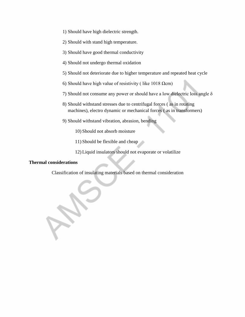
1) Should have high dielectric strength.
2) Should with stand high temperature.
3) Should have good thermal conductivity
4) Should not undergo thermal oxidation
5) Should not deteriorate due to higher temperature and repeated heat cycle
6) Should have high value of resistivity ( like 1018 Ωcm)
7) Should not consume any power or should have a low dielectric loss angle δ
8) Should withstand stresses due to centrifugal forces ( as in rotating
machines), electro dynamic or mechanical forces ( as in transformers)
9) Should withstand vibration, abrasion, bending
10) Should not absorb moisture
11) Should be flexible and cheap
12) Liquid insulators should not evaporate or volatilize
Thermal considerations
Classification of insulating materials based on thermal consideration
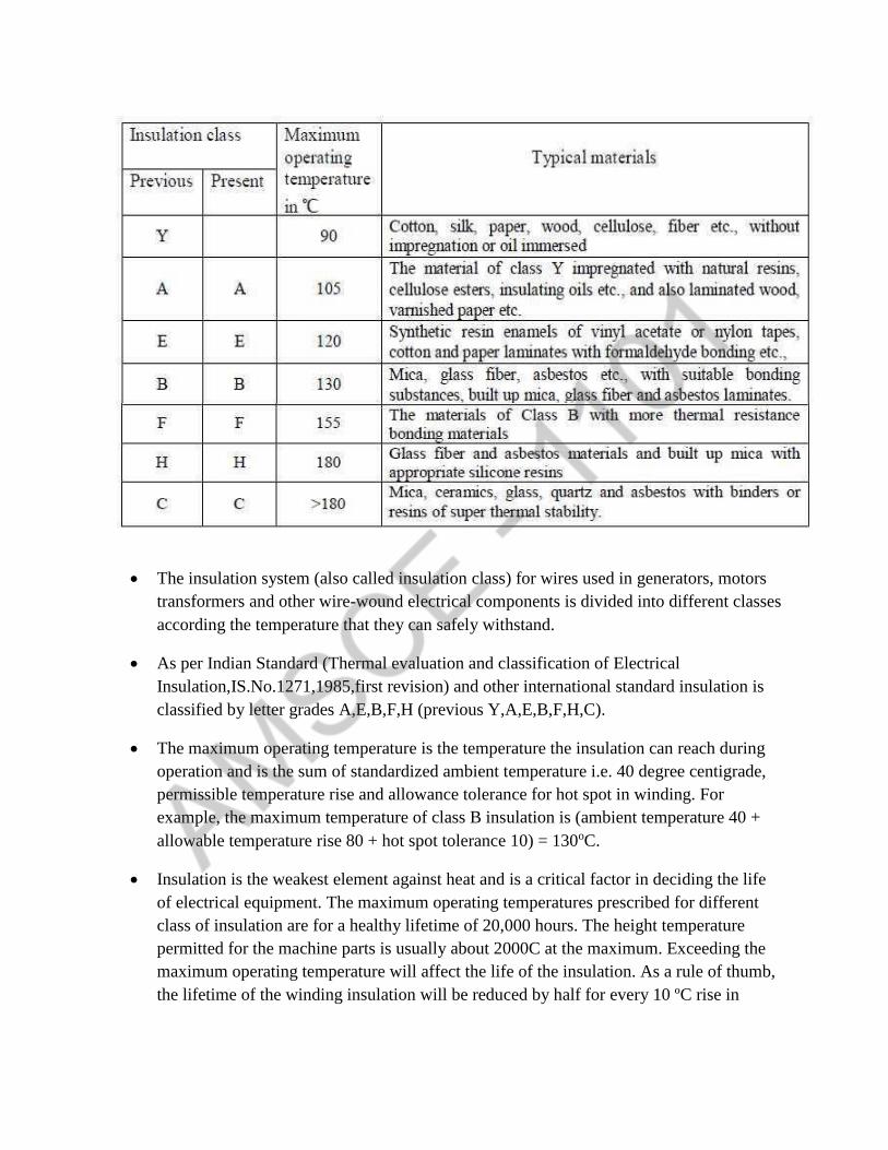
The insulation system (also called insulation class) for wires used in generators, motors
transformers and other wire-wound electrical components is divided into different classes
according the temperature that they can safely withstand.
As per Indian Standard (Thermal evaluation and classification of Electrical
Insulation,IS.No.1271,1985,first revision) and other international standard insulation is
classified by letter grades A,E,B,F,H (previous Y,A,E,B,F,H,C).
The maximum operating temperature is the temperature the insulation can reach during
operation and is the sum of standardized ambient temperature i.e. 40 degree centigrade,
permissible temperature rise and allowance tolerance for hot spot in winding. For
example, the maximum temperature of class B insulation is (ambient temperature 40 +
allowable temperature rise 80 + hot spot tolerance 10) = 130oC.
Insulation is the weakest element against heat and is a critical factor in deciding the life
of electrical equipment. The maximum operating temperatures prescribed for different
class of insulation are for a healthy lifetime of 20,000 hours. The height temperature
permitted for the machine parts is usually about 2000C at the maximum. Exceeding the
maximum operating temperature will affect the life of the insulation. As a rule of thumb,
the lifetime of the winding insulation will be reduced by half for every 10 ºC rise in

temperature. The present day trend is to design the machine using class F insulation for
class B temperature rise.
6. Discuss in detail the factors affecting the choice of specific electric and magnetic loading in
rotating machines.[NOV/DEC2017,NOV/DEC2018]
Specific magnetic loading (Bav)
The specific magnetic loading is defined as the average flux density over the air-gap of a
mixture
totalfluxaroundtheair gap pBav
areaoffluxpathattheair gap DL
Factors that affect the choice of specific magnetic loading
(i) Maximum flux density in iron
Maximum flux density will occur in teeth (particular narrow end of the teeth)
ie Bt is not to exceed maximum specified limit 2 to.2 2/wh m
small machine (which have very narrow teeth width) will have lower specific magnetic loading.
(ii) Magnetising current
Increase in specific magnetic loading will have result in increased magnetising current. The
value of magnetising current is not a serious consideration in d.c machine, But an increased
value of magnetising current in induction result into low power factor
(iii) Core loss
Increase in specific magnetic loading will also increase the core loss and consequently decreased
efficiently and an increased temperature rise.
(iv) Frequently of operation of armature
High speed d.c machine (or) high frequently are machine, specific magnetic loading must be
reduced in order to get lower iron loss so that resonable efficiency is maintained
(v) Size of machine
At a given specific electric loading, if lineal dimension is increased by x times, then core loss
will increase by 3x times & output will increase by
4x times.
Then for the same percentage of core loss in two machines, specific magnetic loading may be
increased slightly for the larger machine
Typical value of bow (2/wh m )
0.4 to 0.8 – D.C Machine
0.3 to 0.6 – Induction motor
0.52 to 0.65 – synchronous machine
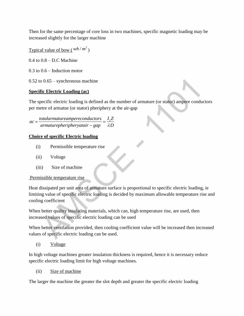
Specific Electric Loading (ac)
The specific electric loading is defined as the number of armature (or stator) ampere conductors
per metre of armatue (or stator) pheriphery at the air-gap
2I Ztotalarmatureampereconductorsac
armaturepheripheryatair gap D
Choice of specific Electric loading
(i) Permissible temperature rise
(ii) Voltage
(iii) Size of machine
Permissible temperature rise
Heat dissipated per unit area of armature surface is proportional to specific electric loading, ie
limiting value of specific electric loading is decided by maximum allowable temperature rise and
cooling coefficient
When better quality insulating materials, which can, high temperature rise, are used, then
increased values of specific electric loading can be used
When better ventilation provided, then cooling coefficient value will be increased then increased
values of specific electric loading can be used.
(i) Voltage
In high voltage machines greater insulation thickness is required, hence it is necessary reduce
specific electric loading limit for high voltage machines.
(ii) Size of machine
The larger the machine the greater the slot depth and greater the specific electric loading

Typical values of ac in amp cord/metre
15000 to 50000 -> D.C machine
5000 to 45000 -> Induction motor
20000 to 40000 -> syn motor
5000 to 75000 -> turbo alternator
Types of duties and ratings
S1 – Continuous duty
S2 – Short time duty
S3 – Intermittent periodic duty
S4 – Intermittent periodic duty with starting
S5 - Intermittent periodic duty with starting & braking
S6 – Continues duty with intermittent periodic loading
S7 - Continues duty with intermittent periodic loading & Braking
S8 - Continues duty with intermittent periodic speed charges
Limitations in design
1. Saturation
2. Temperature rise
3. Insulation
4. Efficiency
5. Mechanical parts
6. Communication
7. Power factor
8. Consumers specifications
9. Standard specifications
Standard specification
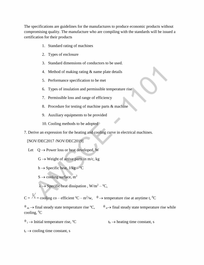
The specifications are guidelines for the manufactures to produce economic products without
compromising quality. The manufacture who are compiling with the standards will be issued a
certification for their products
1. Standard rating of machines
2. Types of enclosure
3. Standard dimensions of conductors to be used.
4. Method of making rating & name plate details
5. Performance specification to be met
6. Types of insulation and permissible temperature rise
7. Permissible loss and range of efficiency
8. Procedure for testing of machine parts & machine
9. Auxiliary equipments to be provided
10. Cooling methods to be adopted
7. Derive an expression for the heating and cooling curve in electrical machines.
[NOV/DEC2017 /NOV/DEC2019]
Let Q Power loss or heat developed, W
G Weight of active parts in m/c, kg
h Specific heat, J/kg – oC
S cooling surface, m2
λ Specific heat dissipation , W/m2 – oC,
C = 1 = cooling co – efficient oC – m2/w, temperature rise at anytime t, 0C
m final steady state temperature rise oC, n final steady state temperature rise while
cooling, 0C
i Initial temperature rise, oC th heating time constant, s
tc cooling time constant, s
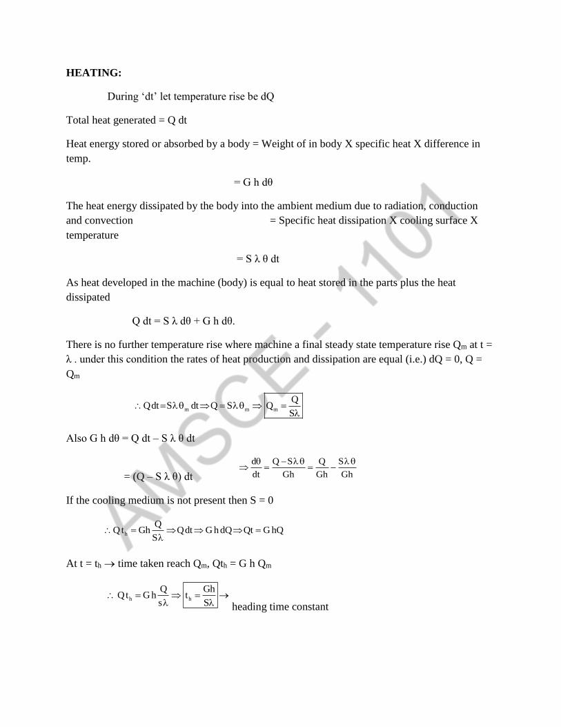
HEATING:
During ‘dt’ let temperature rise be dQ
Total heat generated = Q dt
Heat energy stored or absorbed by a body = Weight of in body X specific heat X difference in
temp.
= G h dθ
The heat energy dissipated by the body into the ambient medium due to radiation, conduction
and convection = Specific heat dissipation X cooling surface X
temperature
= S λ θ dt
As heat developed in the machine (body) is equal to heat stored in the parts plus the heat
dissipated
Q dt = S λ dθ + G h dθ.
There is no further temperature rise where machine a final steady state temperature rise Qm at t =
λ . under this condition the rates of heat production and dissipation are equal (i.e.) dQ = 0, Q =
Qm
m m m
QQdt S dt Q S Q
S
Also G h dθ = Q dt – S λ θ dt
= (Q – S λ θ) dt
d Q S Q S
dt Gh Gh Gh
If the cooling medium is not present then S = 0
h
QQt Gh Qdt G h dQ Qt G hQ
S
At t = th time taken reach Qm, Qth = G h Qm
h h
Q GhQt G h t
s S
heading time constant
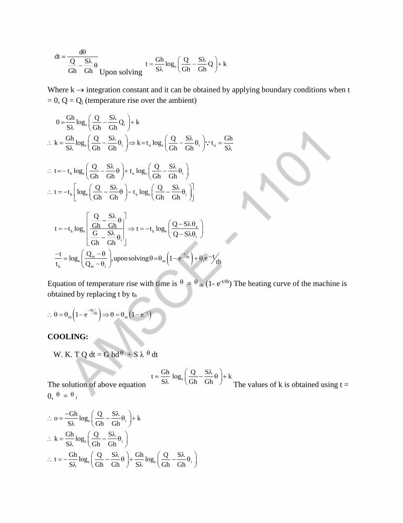
ddt
Q S
Gh Gh
Upon solving e
Gh Q St log Q k
S Gh Gh
Where k integration constant and it can be obtained by applying boundary conditions when t
= 0, Q = Qj (temperature rise over the ambient)
e i
e i n e i n
Gh Q S0 log Q k
S Gh Gh
Gh Q S Q S Ghk log k t log t
S Gh Gh Gh Gh S
h e n e i
h e n e i
Q S Q St t log t log
Gh Gh Gh Gh
Q S Q St t log t log
Gh Gh Gh Gh
e
h e h e
ii
tm th
e m i
h m i
Q SQ SGh Ght t log t t log
G S Q S
Gh Gh
Qt tlog ,uponsolving 1 e etht Q
Equation of temperature rise with time is = m (1- e-t/th) The heating curve of the machine is
obtained by replacing t by th
th
1thm m1 e 1 e
COOLING:
W. K. T Q dt = G hd + S λ dt
The solution of above equation e
Gh Q St log k
S Gh Gh
The values of k is obtained using t =
0, = i
e i
e i
e e i
Gh Q So log k
S Gh Gh
Gh Q Sk log
S Gh Gh
Gh Q S Gh Q St log log
S Gh Gh S Gh Gh
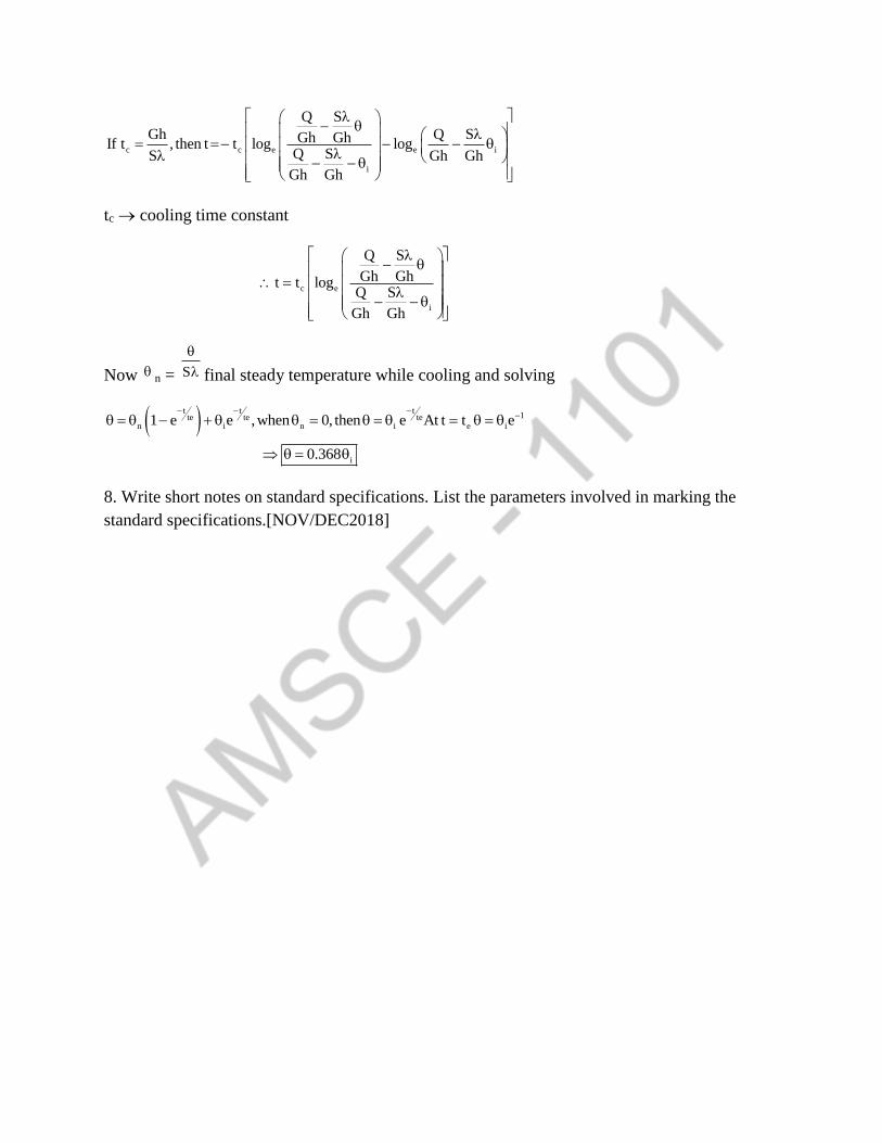
c c e e i
i
Q S
Gh Q SGh GhIf t , then t t log logQ SS Gh Gh
Gh Gh
tc cooling time constant
c e
i
Q S
Gh Ght t logQ S
Gh Gh
Now n = S
final steady temperature while cooling and solving
t t t
1te te ten i n i e i
i
1 e e ,when 0, then e At t t e
0.368
8. Write short notes on standard specifications. List the parameters involved in marking the
standard specifications.[NOV/DEC2018]


UNIT II
DESIGN OF TRANSFORMERS
PART A
1. What is window space factor (Nov /Dec 2016,Nov/Dec2019)
The Window space factor is defined as the ratio of copper area of window to total area of
window.
2. How heat is dissipated in a transformer? [Nov / dec2016)
The heat dissipation in a transformer occurs by conduction, connection and radiation.
3. Distinguish between core type and shell type transformers ( may / June 2016).
CORE TYPE SHELL TYPE
1.Easy in design and construction
2.Has lap mechanical strength
3.Better heat dissipation from windings
1.Comparatively complex
2.Has high mechanical strength
3.Heat is not easily dissipated from windings
since it is surrounded by core.
4. Why are the cores of large transformers built-up of circular section? (May/June2016)
*Circular cross section is preferred to obtain the optimum core within the circumscribing
circle of core.
*To provide high tensile strength
*To keep the hot spot temperature within specified limits.
5. Why stepped core are generally used for transformer (May/ June 2015)
Or
What are the advantages of stepped core in transformers?[Nov/Dec2018]
When stepped cores are used the diameter of the circumscribing circle is minimum for a
given area of the core, this helps in reducing the length of mean turn of the winding with
consequence reduction in both cost of copper and copper loss.
6. Why circular coils are preferred in transformer (May / June 2015).
The excessive leakage fluxes produced during short circuit and over-load, develop sever
mechanical stresses on the coils.
On circular coils these forces are radial and there is no tendency for the coil to change its shape.
But on rectangular coils the forces are perpendicular to the conductors and ends to deform the
coil in circular form.
7. Define the term voltage regulation. (May/June 2014)
It is defined as the ratio of difference between no-load voltage and full load voltage to no-
load voltage.
8. Mention the various methods of cooling for larger power transformers.
*Oil natural air forced
Oil natural water forced
Oil forced air natural
Oil forced air forced
Oil forced water forced.
9. Classify the transformer according to cooling methods?
According to cooling methods the transformers can be classified as follows,
Air Cooled transformer
Oil cooled transformers
Water cooled transformers
10. List the different types of windings used in core type transformers,
The different types of windings employed in core type transformer all.
Cylinder winding
Cross-over winding
Helical winding
Disc and cooking was disc winding,
Double helical winding
Aluminium foil winding
Multi layer helical winding
11. What do you mean by stacking factor or Iron space factor?[Apr/May2011]
In transformers, the core is made of lamination and the laminations are insulated from
each other by a thin coating of varnish. Hence when the laminations are stacked to form the core,
the actual iron area will be less them the core area.
The ratio of iron area and total care area is called stacking factor.The value is usually 0.9
12. Define copper space factor.
The copper space factor is the ratio of conductor area and window area in case of
transformers.
13. Write down the output equation of 1-phase and 3 phase transformers.
Single-Phase Transformer; Q = 2.22BmfKwAwAiδ x10-3
Three Phase Transformer; Q = 3.33 f BmKwAwAiδ x10-3 kVA
14. What are the various types of transformers construction based,
Care type x shell type
Application based
Distribution transformers
Power transformers
Special transformers
Instruments transformers
Electronics transformers
15. What are the factors to be considered for selecting the cooling method of transformers?
The choice of cooling method depends on kva rating of transformers, size, application
and the site condition where and the site condition where it will be installed.
16. Classify the transformers according to cooling method?
According to cooling method the transformers can be classified as
Air cooled transformers
Oil cooled transformers
Water cooled transformers
17. How to design the winding of a transformer?
The winding design consists of estimation of number of turns and area of cross section of
winding conductions.
Usually the number of burns in low voltage winding is estimated by assuming ernf per
turn and the turns of high voltage winding are estimated from the voltage ratio.
Number of turns in low voltage winding} equation
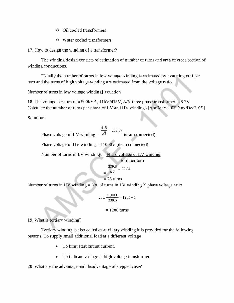
18. The voltage per turn of a 500kVA, 11kV/415V, Δ/Y three phase transformer is 8.7V.
Calculate the number of turns per phase of LV and HV windings.[Apr/May 2005,Nov/Dec2019]
Solution:
Phase voltage of LV winding =
415239.6
3v
(star connected)
Phase voltage of HV winding = 11000V (delta connected)
Number of turns in LV windings = Phase voltage of LV winding
Emf per turn
=
239.627.54
8.7
= 28 turns
Number of turns in HV winding = No. of turns in LV winding X phase voltage ratio
11,00028x 1285 5
239.6
= 1286 turns
19. What is tertiary winding?
Tertiary winding is also called as auxiliary winding it is provided for the following
reasons. To supply small additional load at a different voltage
To limit start circuit current.
To indicate voltage in high voltage transformer
20. What are the advantage and disadvantage of stepped case?
Advantage
For the same area of cross – section the stepped cores will have lesser diameter of
circumscribing circle than square mean turn of the winding with consequent reduction in caste of
copper and copper loss.
Disadvantage
With large number of steps a large number of different sizes if laminations have to be
used. This results in higher labour charges for shearing assembling different types of
laminations.
21. How does a distribution transformer differ from a power transformer?[NOV/DEC2017]
Solution:
Distribution transformer are used in distribution network where as power transformers
are used in transmission networks
Distribution transformer voltages are 11 KV, 6.6 KV, 3.3 KV, 440 V on the other hand
power transformer voltage are 33 KV, 110 KV, 220 KV, 400 KV
Part B:
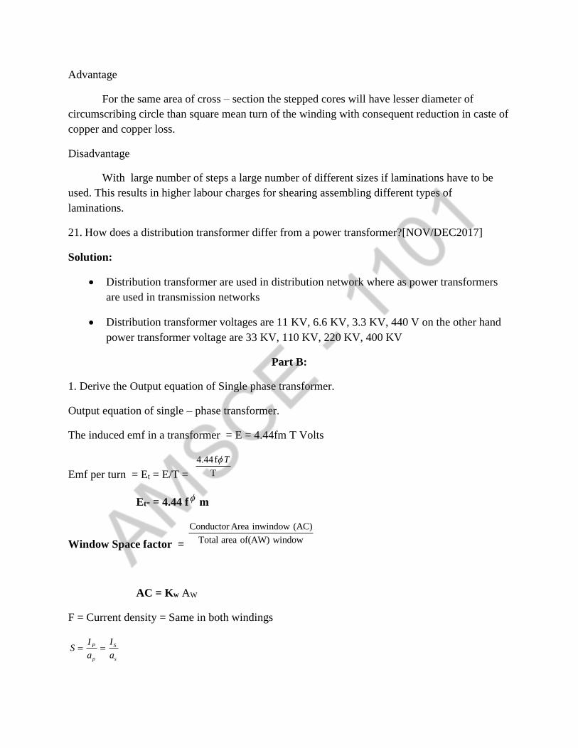
1. Derive the Output equation of Single phase transformer.
Output equation of single – phase transformer.
The induced emf in a transformer = E = 4.44fm T Volts
Emf per turn = Et = E/T =
4.44f
T
T
Et- = 4.44 f m
Window Space factor =
Conductor Area inwindow (AC)
Total area of(AW) window
AC = Kw AW
F = Current density = Same in both windings
SP
p s
IIS
a a
, SPp s
s
IIa d
a
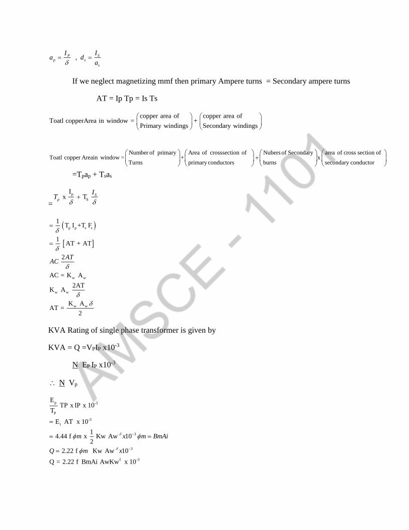
If we neglect magnetizing mmf then primary Ampere turns = Secondary ampere turns
AT = Ip Tp = Is Ts
copper area of copper area ofToatl copperArea in window = +
Primary windings Secondary windings
Number of primary Area of crosssection of Nubers of Secondary area of cross section of Toatl copper Areain window = + x
Turns primary conductors burns secondary conductor
=Tpap + Tsas
=
p
S
Ix T S
p
IT
p p s s
w w
w w
w w
1T I +T F
1AT + AT
2
AC = K A
2ATK A
K AAT =
2
ATAC
KVA Rating of single phase transformer is given by
KVA = Q =VPIP x10-3
N EP IP x10-3
N Vp
p -3
P
-3
t
3
3
f -3
ETP x IP x 10
T
E AT x 10
14.44 f x Kw Aw 10
2
2.22 f Kw Aw 10
Q = 2.22 f BmAi AwKw x 10
m x m BmAi
Q m x

2. Derive the Output equation of three phase transformer.(Nov/Dec2018)
Output equation of three phase transformer the induced emf per phase E – 4.47f m T
Emf per turn = E/T = 4.44 f m T
C
W
A
AwK
AC = KW AW
Note: one window is considered
Current density =
IP S
P
I
sI,PI
ap as
On neglecting magnetising ampere turns
AT = ap Tp = as Ts
Total copper area in window = Ac = 2Tp ap + 2 Ts as
PIAC 2Tp 2
δ
2AT + AT
8
4AT
S
S
C
IT
A
AC =Kw Aw
4ATKw Aw
1Kw Aw x
4AT
Q = 3Vp IP x 10-3 = 3 Ep Ip x 10-3 KA
-3
-3
Ep3x x Tp Ip x 10
Tp
13x 1.1f m x x Kw Aw
4
Q=3.33f Bm AiAw Kwf X 10
3. Calculate the core and window area required for a 1000KVA , 6600/400V, 50HZ , single
phase core type transformer. Assume a maximum flux density of 1.25 wb/m2 Voltage per turn =
30V. Window space facker = 0.32.
Given data
KVA = 1000, F = 50Hz Bm = 1.25 wn/m2 Vp = 6600V, Vs = 400V , = 2.5 A / mm2
Et = 30v , Kw = 0.32 1-phae case type.
Solution:
Emf per turn , Et -=- 4.44 f m f
300.135 /
4.44 4.44 x 50
EtQm wb
f
Bm =
Qm
Ai
2
6 2
0.13510. 108
1.25
0.108 x 10
QmAi m
Bm
mm
Q = 2.22 f Bm Ai Kw Aw f x 10-3
6 -3
1000
2.22x50 x 1.25 x 0.108 x 0.32 x 2.5x 10 x 10
= 0.0834 m2
= 0.834 x 106 mm2
4. Determine the dimensions of care and window for a 5KVA, 50Hz, 1- phase core type
transformer. A rectangular core is used with long side device as long as start 57 the window
height is 3 times the width voltages per turn = 1.8V. Space factor = 0.2 = 1.8A /mm2 Bm =
1wb/m2
Data given
Q = 5kVA , F = 50Hz = 1.8A/mm2
BM = 1 Wb/m2 Ef = 1.8V Kw = 0.2
Core type, rectangular core , I phase long side = 2 x short size
Hw = 3Ww

IMAGE
Emf per turn Et = 4.4 f m
1.80.0081
4.4 4. 4 50
tEm wb
uf u
Net are area
20.00810.0081
1
mAi m
Bm
Cross core area , Agi
20.00880.0009
0.9f
Aim
S
Cross section of core is rectangle Hence
Agi = length x breadth = a x b
Given =- a = 2b
Agi = 2b x b = 2b2
b
Agi 0.0090.067
2 2m
a = 2b = 2x 0.067 = 0.134m
Q = 2.22f Bm Ai Kw Aw f x 10-3
Aw = -32.22 x10m w
Q
f B Ai K
= 6 -3
5
2.22 x 50 x 1 x 0.0081 x 0.2 x 1.8 x10 x10
= 0.0154m2
Window area Aw = Hw Ww
Hw = 3Ww
Aw = Hw Ww = 3Ww x Ww = 3Ww2
0.0154Ww = 0.716
3 3
Awm
Hw = 3Ww = 3 x 0.0716

= 0.2145m
The Net core area . Ai = 0.0081m2
Dimensation of the core a x b = 0.1314 x 0.067m
Window area Aw = 0.0154m2
Dimension of window , Hw x Ww = 0.2148 x 0.0716m
5. Estimate the main dimensions including winding conductor area of a 3 phase A- y core type
transformer raped at 300kva, 6600/440V, 50Hz . A suitable core with 3 – steps having a
circumscribing circle of 0.25m diameter and a leg spacing of 0.4m is available amf per turn =
8.5V s = 2.5A/mm2 Kw = 0.28 , sf = 0.9(Nov/Dec2017)
Data given
3- Phase A – y 50hz, Et = 8.5v 3- Stepped core, s = 2.5 A/mm2 correct type 300Km , d = 0.25
Kw =- 0.28 leg Spacing = 0.4m sf = 0.9 6600/4400
Let 440v side be secondary
Vs = 440V/
Vp 6600V
Vs =
440254
3V
Es Vs
Et = Es/Ts
Voltage ratio of transformer =
254
6600
Vs
Vp
6600x 30 x
254
VpTp Ts
Vs
= 779.5 N 780 turns
-33 x 10Q VcpIlp
3 Vls Ils x 10-3
-33 x 10
QIlp
Vlp

-3
30026.24
3 6600 x 10Ilp A
Since primary is delta connected phase current on primary side.
Ip = 3
Ilp
26.2415.15A
3Ip
2393.65157.5mm
2.5
Ipap
Copper area in window
Ac = 2[ap Tp + as Ts]
= 2[6.06 x 780 + 157.5 x 30]
18903.6 mm2
Window Area
18903.6
0.28
AcAw
Kw
67512.86mm2
67512.86 x 10-6 m2
0.0675m2
Area of circumscribing circle =
22(0.25)
0.0494
m
For 3-stepped core
crosscoreArea (Agi)0.84
Area of circumscribing
Agi = 0.84 x 2 / 4d
0.84 x 0.049 = 0.41m2
Ai = Sf x Agi
= 0.9 x 0.041
= 0.0369 m2
= 0.037 x 106 mm2
Given that leg spacing = 0.4m = Ww
Height of window Hw =
Aw
Ww
0.06750.15
0.45m
Number of primary turns/phase Tp = 780
Ni=umber of secondary turns/phase = Ts = 30
ap = 6.06mm2
as = 157.5mm2
At = 0.0369 m2
Aw = 0.0675m2
Hw = 0.15m
Ww = 0.45m
6. Calculate the main dimensions and windings details of a 100KVA, 2000/400Volts, 50HZ,
single phase shell type, oil immersed self cooled transformer. Assume Voltage per turns 10V
flux density in core 1.1wb/m2 , current density 2A/mm2 Window space factor = 0.33
The ratio of window height to window width and ratio of care depth o width of control limb =
2.5 the skading factor is 0.9.
10Ai =
4.44 4.44 x 50 x1 1
Et
m f Bm
0.441m2
0.04095Agi =
0.9
Ai
Sf
0.0455m2
2.52
b
a
Agi = 2a x b
2.5 (2a)2 = 0.0455
2 0.04552 0.0182
2.5a
2a = 0.1349 0.135
Width of central limb = 2a = 2.5 x 0.135
Core depth = b = 2.5 x 2a = 2.5 x 0.135
= 0.3375m
The Yoke core half of the flux in the central limb. Assuming the same flux density in the core as
in the limb the area of yoke is equal to half the area of the central limb
0.0455Corss area of area Ay =
2
= 227.75 x 10⁻³m2
Depth of yoke Dy = b= 0.3375m
Height of yoke Hy =-
-322.275x100.0675
0.3375m
IMAGE
The side limbs carry half of the flux in the central limb. Therefore the width of side limbs is half
of the width of central limbs width of side a = 0.0675m
Q = 0.22f Bm Kw f Af Aw x 10-3
100 = 2.22 x 50 x 1.11 x 0.32 x 2x 106 x 0.041 x Aw x 10-3
Aw = 0.0303 m2
Hw Ww = 0.0303
Hw3
Ww
3Ww2 = 303 x 10-4
Ww = 0.1m Hw = 0.3m
H = Hw + 2Hy = 0.3 + 2 x 0.0675

= 0.435m
W = 2Ww = +4a = 2x0.1 + 4 x 0.675
= 0.47m
b- 0.3375m
H.V Winding turns = Tp
2000200
10
L.V Winding turns = Ts =
40040
10
H.V Winding Current = Ip =
100 x 100050A
2000
H.V Winding conductor area = ap =
25025
2mm
L.V Winding Current = Is =
100 x 1000250A
400
L.V Winding Area = as =
2250125
2mm
7. The tank of 1250 KVA, natural oil cooked transformer has the dimension length width and
height as 0.62 x 1.55 x 1.85m respectively. The full load loss = 13.1Kw, loss dissipation due to
redactions = 6w/m2oc loss dissipation due to convection due to provision of tubes = 40%
temperature rise = 40oc. Length of each tube = 1m, diameter of tube = 50mm. Find the number
of tubes for this transformer Neglect the top and bottom surface of the tank as regards the
cooling
Data given:
KVA = 1250
Tank dimenastion = 0.65 x 1.55 x 1.85m
l1 = 1m conv = 6.5w/m2 –C
dt = 50mm red = 6w / m2 –C
= 40oc . Improvement in cooling = 40%
Full load Loss = 13.1 Kw

LT = Lenght = 0.65m
WT = Width = 1.55m
HT = Height = 1.85m
Image
Heat dissipating surface of bank = Total Area of Vertical side
St =2 [LT HT + WT AT]
2 HT [LT + WT]
2 x 1.85 x [0.65 + 1.55]
= 8.14m2
Loss dissipated by tank walls by rediation and convection = (6+6.5) St
= 12.5 St
Let heat dissipating area of tubs = XSt
Loss dissipated by cooling tubes due to convection = 6.5 x t
140x S
100
= 9.1 txS
Total loss dissipated by tank and tubes - = 12.5 St + 9.1 txS
= St (12.5 + 9.1 x)
Temperature rise in transformer Total Loss
with cooling tubes Total Loss dissipated
Total loss = Pcos = 13.1 Kw = 13.1 x 10³w
313.1 x10
12.5 9.( )S x
313.1 1012.5 9.1
t
xx
S

-3
3
1 13.1 x 1012.5
9.1
1 13.1 x 1012.5 3.0476
9.1 40 x8.14
tS
Total Area of tubes = xst = 3.0476 x 8.14
= 24.8075 m2
Total number of cooling tubes = Total Area of tubes
Area of each tube
Area of each tube = x 50 x 10-3 x 1 = 0.157m2
Total number of cooling tubes
24.8075158
0.157
tubes
The diameter of the tube is 50mm and the standard distance between the tube is half of the
diameter and so let distance between tubs = 25mm.
The width of the bank is 1550mm. If we leave an edge spacing of 62.5mm on either sides then
we can arrange 20 tubes width wise with a spacing of 75mm between centres of tubes on length
we can arrange 8 tubes with same spacing as that of width wise tubes. But one row is not
sufficient to accommodate the required 158 cooling tubes. Hence three rows of cooling tubes are
provided on both length wise and width wise
The total number of tubes provided = 160
8. A 250 KVA . 660/440V 3-Phase core type transformer has a total loss of 48000 watts on full
load the transformer bank is 1.255m in height and 1m x 0.5m in plan. Design a suitable scheme
for cooling tubes if the average temperature rise i to be limited to 35oC. The diameter of the tube
is 50mm and are spaced 75mm form each other the average height of the tube is
1.05m(Nov/Dec2018,Nov/Dec2019)
Data given
KVA = 250 , = 35oC , dt = 50mm
Lt= 1.05m Tank dimension = 0.5 x 1 x 1.25m
Total power loss = 4800W
Distance between tube centers = 75mm

6600/440V 3Phase Corev type
IMAGE
LT = Lenght = 0.5m
WT = Width = 1m
HT = Height = 1.25m
t
Heat dissiatingS = Totalarea of Vertical sides
surfaceof tank
= 2 [LT HT + WT HT]
2 HT [LT + WT]
2 x 1.25 x [0. 5 + 1] = 3.75m2
Loss dissipated by tank walls by radiation and convection = (6+6.5) St
= 12.5 St
Let heat dissipating area of tubs = XSt
Loss dissipated by cooling tubes due to convection = 6.5 x t
135x S
100
= 8.775 txS N 8.8 txS
Total loss dissipated by tank and tubes - = 12.5 St + 8.8 txS
= St (12.5 + 8.8 x)
Temperature rise in transformer Total Loss
with cooling tubes Total Loss dissipated
Total loss, P loss = 4800w
4800
12.5 8.8Q
St x

1 480012.5
8.8
1 480012.5
8.8 35 x 3.75
t
XS
= 2.7354
Total area of cooling tubes = x st = 2.7354 x 3.75
= 10.2578m2
Area of each cooling tube = dr lt = x 50 x 10-3 x 1.05
= 0.1649m2
Number of Totalarea of tubes
cooling tube Area of each tubetn
10.257862.206 62 tubes
0.1649
The width of the bank is 1000mm. If we leave an edge spacing of 87.5mm on either sides then
we can arrange 12 tubes width wise with a spacing of 75mm between centres of tubes.
The Length of the bank is 500mm. If we leave an edge spacing of 100mm on either sides then we
can arrange 5 tubes width wise with a spacing of 75mm between centres of tubes.
But one row is not sufficient to accommodate the required 62 cooling tubes. Hence 2 rows of
cooling tubes are provided on both length wise and width wise
The total number of tubes provided = 64
They are arrange as 2 rows an widthwise each row of 12 and 11 tubes and 2 rows on length wise
with each row consisting of 5 and 5 tubes.
9. Explain the different methods of cooling of Transformers(Apr/May2019)
The losses developed in the Transformers cores and windings are converted into thermal
energy and cause heating of corresponding Transformers parts
The heat dissipation in temperature occurs by conditions convection and radiation
The paths of heat flow in Transformers
Heat developed in core (or) ending to their outer surface in contact with
the oil (conduction)
From the outer surface of a Transformers parts to the oil that cools it
(convection)
From the oil to the wall of a cooler eg wall of tank (convection)
Form the walls of the cooler to the cooling medium air -(or) water (
radiation)
The various methods of cooling Transformers are
1. Air natural
2. Air
3. Oil natural
4. Oil natural – air forced
5. Oil natural water forced
6. Forced circulation of oil
7. Oil forced - water forced
The choice of cooling method depends upon the
Size
Type of application
Condition of the site
Natural cooling is suitable upto 10MVA the forced oil and oil air circulation are employed for
Transformers of capacities 30mvA and upwards
The forced oil and water is used for Transformers designed for power plants
10. Explain briefly cores used in Transformers?
For core types Transformers the cross – section may be rectangular square (or) stepped
Circular coils are used for distribution Transformers
Square and stopped cores are used for power Transformers
For shell type rectangular cross section is used usually rectangular core is used for small
and low voltage Transformers

In square core the diameter of the circumscribing circle is larger than the diameter of
stepped core of same area of cross section thus when stepped core are used the length of mean
turns of winging reduced with consequent reduction in both costs of copper and loss.
However with large number of steps a large number of different sizes of lamination have
to be used this results in higher labour changes for shearing and assembling different types of
laminations
Square core
IMAGE
D = diameter of circumscribing circle
(or)
a = Side of square
Diameter of circumscribing circle 2 2d a a
22 2d a a
2
da
Gross core area = Agi = a2
2
2
d = 0.5 d2
Agi = 0.5 d2
Sf = 0.9 stocking factor
Ai = Sf x Agi = 0.9 x 0.5 d2
Ai = 0.45d2
Area of circumscribing circle =
2
4d
Ratio of area of core and circumscribing circle
Ratio Square core circumscribing
circle
3- stepped
core
4 –stepped
core
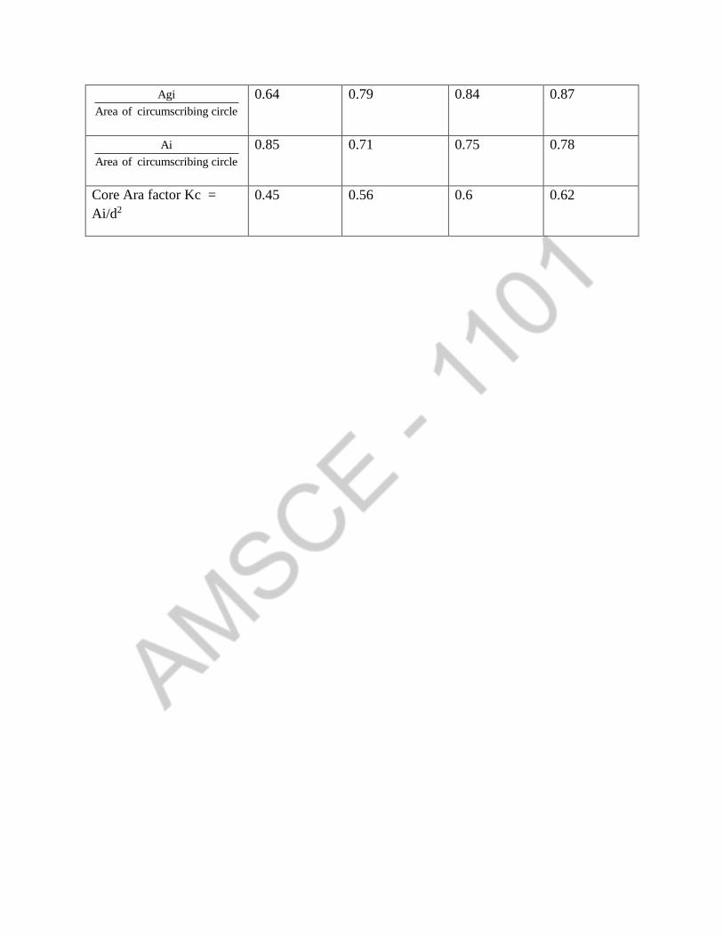
Agi
Area of circumscribing circle
0.64 0.79 0.84 0.87
Ai
Area of circumscribing circle
0.85 0.71 0.75 0.78
Core Ara factor Kc =
Ai/d2
0.45 0.56 0.6 0.62

Unit-3
Design of DC Machines
PART – A
1. Write the expression for output coefficient of D.C machines
Co = 2 3*10Bgac
2. Mention guiding factors for the selection of number of poles [NOV/DEC 2016]
Factors to be considered for the selection of number of poles in d.c machine
(i) Frequency
(ii) Weight of iron parts
(iii) Weight of copper
(iv) Length of commentator
(v) Labour charges
(vi) Flash over and distraction of field form
3. What is meant by magnetic circuit calculation [MAY/JUNE 2016]
The calculation of reductance, flux density and mmf for various sections of magnetic circuit are
commonly referred to as magnetic circuit calculations
4. What are the factors to be considered in the design of Commutator of a D.C machine?
Peripheral speed
Number of coils in the armature
Number of brushes
Voltage between adjacent Commutator segment
Commutator losses
5. Write down the output equation of a d.c machine [MAY 2013]
Output Equation of D.C machine = Po = Co 2
nD L Kw
Po = Power developed in armature of dc machine
Co = Output coefficient
Co = 2 3 3*10 /Bavac Kw m ps
6. Mention the factors governing the length of armature core in a d.c machine [NOV/DEC 2014]
Dimensions of the pole
Moment of inertia
Pheripheral speed
Voltage between adjacent Commutator segments
7. Mention the factor that, governing the choice of number of armature slots in a d.c machine
The factor governing the choice of armature of armature slot are
Slot pitch
Slot loading
Flux pulsation
Commutation
Suitability for winding
8. Why square pole is preferred [MAY/JUNE 2015]

If the cross-section of the pole-body is square then the length of the mean turn of field winding is
minimum. Hence to reduce the copper requirement a square cross-section is preferred for the
poles of dc machine
9. Define copper space factor of coil [MAY/JUN2015]
The copper space factor of a coil is defined as the ratio of conductor area and the area of cross-
section of the coil.
Copper Space Factor = sec
ConductorArea
Areaofcross tionofthecoil
Conductor Area = Number of turns * Area of cross – section of conductor
10. State the relation between the number of Commutator number of armature coils in a d.c
generator
The number of Commutator segment is equal to the number of coils in a d.c generator
cc
D
C
c = Commutator segment pitch
C = No of coils
cD = Diameter of Commutator
11. State the conditions of electrical armature windings electrical symmetry is achieved if the
conductors are placed symmetrically with regard to the field systems. For this the number of slot
and Commutator segments should be multiples of pair of pole
12. Discuss the parameters governing the length of Commutator
The length of the Commutator depends upon the number of brushes and clearance between the
brushes. The surface area required to dissipate the heat generated by the Commutator losses is
provided by keeping sufficient length of Commutator
13. How the effects of armature reaction can be reduced?
The effects of armature reaction can be reduced by
Increasing the length of air-gap at pole tips
Increasing the reductance at pole tips
Providing compensating winding and interpoles
14. What is the effect of interpole on main pole?
In case of generator the interpole will magnetize the leading edge and demagnetize the trailing
edge of main pole. In case of motor the interpoles will demagnetize the leading edge and
magnetize the trailing edge of main pole.
15. How do design the number of brushes for a dc machine?
The number of brush locations are decided by the type of winding. In lap-winding the number of
brush locations is equal to number of poles and in wave winding it is always two.
In each location there may be more than one brush mounted on a spindle, whenever the current
per brush location is more than 70A. Hence the number of brushes in a spindle are selected such
that each brush does not carry more than 70A
16. Calculate the output coefficient of a dc shunt generator from the given data. 20.89 /gB wh m , ac = 32000 amp.cond/m = 0.66
Co = 2 3*10Bgac

= 2 *0.66*0.89*32000*
310
=185.5 kw/3m -ps
17. What are the factors to be considered for the choice of specific magnetic loading? And give the
range
The choice of specific magnetic loading depends on the following
Flux density in teeth
Frequency of flux reversals
Size of machine
Range of specific magnetic loading in d.c machine is = 0.4 to 0.8 2/wh m
18. What are the factors to be considered for the choice of specific electric loading? And give the
range.
The choice of specific electric loading depends on the following.
Temperature rise
Speed of machine
Voltage
Size of machine
Armature reaction
Commutation
Range of specific Electric loading = 15000 to 50000 amp.cord/m
19. What are the factors to be considered for estimating the length of air-gap in d.c machine
The factors to be considered for estimating the length of air-gap are
Armature reaction
Cooling
Iron losses
Distertion of field form and noise
20. State any three conditions in deciding the choice of number of slots for a large dc machine
The slot loading should be less than 1500 ampere conductors
The number of slot per pole should be greater the (or) equal to 9 to avoid sparking
The slot pitch should be between 25 to 35mm
21. Explain how depth of armature core for a dc machine is determined
2c
, c
c
c
AB
2 cB
cA = i cL d
i cL d = 2 cB
2c
i c
dL B
=Flux per pole
c = Flux in armature core
cB =Flux density in armature core

iL =Net iron length of armature
=Depth of armature core
mb=Area of cross-section of armature core
PART-B
1. Explain the procedure for the selection of number of poles in d.c machine[NOV/DEC2-16]
The number of poles used in D.c machines has an important bearing upon the magnetic and
electric circuits. The selection of number of poles depends on
(i) The frequency should lie between 25 t0 50 Hz
(ii) The value of current per parallel path is limited to 200 ampc. Thus the current per brush
arm should not be more than 400mps
Current per parallel path = aI
plap winding
=2
aI for lap winding
Current per brush arm = 2 aI
p lap winding
= aI lap winding
P=number of poles
(iii) The armature mmf should not be too large. The normal values of armature mmf per pole
Armature mmf per pole
Output in KW Armature mmf per pole in AT
Upto 100
100 to 500
500 to 1500
Over 1500
5000 (or) less
5000 to 7500
7500 to 10000
Upto 12500
(iv) If there are more than one choice for ch of poles which satisfies the above three conditions,
then choose the largest value for poles. This results in reduction in iron and copper
By increasing the number of poles, the weight iron in the armature core can be
decreased
The overall diameter of the machine decreases as the number of poles is increased.
The use of large number of pole in increased danger of flash over between adjacent
brush arms
With the increase in number of poles labor charges will increase
With the increase in number of poles there is reduction in distortion of field from
under load conditions

2. For a preliminary design of a 50 Hp, 230v, 1400 rpm, dc shunt motor. Calculate the armature
diameter and core length, number of poles and peripheral speed. Take Bav = 0.5 wh/sq.m ar/m =
25000 efficiency = 0.9[Nov/Dec 2016]
Solution:-
50o
Hpp , v = 230v , N = 1400rpm, Bav = 0.5 wb/sq.m, ac/m = 25000, = 0.9
Power input = Pi = P/ = 50*0.746
0.9
41.44KW
Also power input Pi = VI*310
I = 3*10
Pi
V =
3
41.44
230*10
= 180.17A
Armature current = Ia = I = 180.17A
Since the armature current is less than 200A, the current per parallel path will not exceed the upper
limit 200A
Let, P = 2, f = 120
PW =
2*1400
120 = 23.33 Hz
P = 4, f = 4*1400
120 = 46.66 Hz
P = 6, f = 6*1400
120 = 70
The frequency of flux reversals should lie in the range of 25 to 50 Hz. For minimum cost the highest
possible choice of poles should be choosen.
Hence the number of poles P = 4
Output coefficient Co = 2 Bav ac*
310
= 2 * 0.5 * 25000*
310
= 123.370 KW/3m nps
For dc motor, power developed in armature = Pa P = 50*0.726 = 37.3 KW
Pa = co2D Ln
M
= o
Pa
C n =
37.3
1400123.370*( )
60
KW
37.3
2878.633 = 0.01296
3m
Let us assume a square pole face for a square pole face 0.7L
c
L = 0.7c = 0.7 D
p
=
0.7*
4
D

L = 0.5498D 2D L= 0.01296 2D (0.5498D) = 0.01296
3D = 0.01296
0.5498
D = 0.01296
30.5498
= 0.2867m
Va = nD
= *0.2867*1400
60
= 21.016 3m
L = 0.1576m P =4
D = 0.2867m
Va = 21.0163m
3. Explain the various steps involved in the design of shrunk field winding of dc machine
(I) Determine the dimensions of the pole. Assume suitable value of leakage coefficient
form leakage co efficient table and flux density in the range 1.2 to 1.7 wb/m2
flux in the pole body Pp = cr
Area of pole body = P
P
for cylindrical pole
Diameter of pole body dp= 4Ap
for rectangular pole
Length of pole Lp = L - 10.00/to 0.015
Net iron length of pole Lpi = 0.9Lp
Width of the pole bp Ap
Lpi
(ii) Determine the length of mean turn of Field coil. Assume a suitable depth of field winding
from (Depth of field winding table)
for rectangular field coils
Length of mean tune Lmt = 2 Lp + bp + 2df
For cylindrical field colis
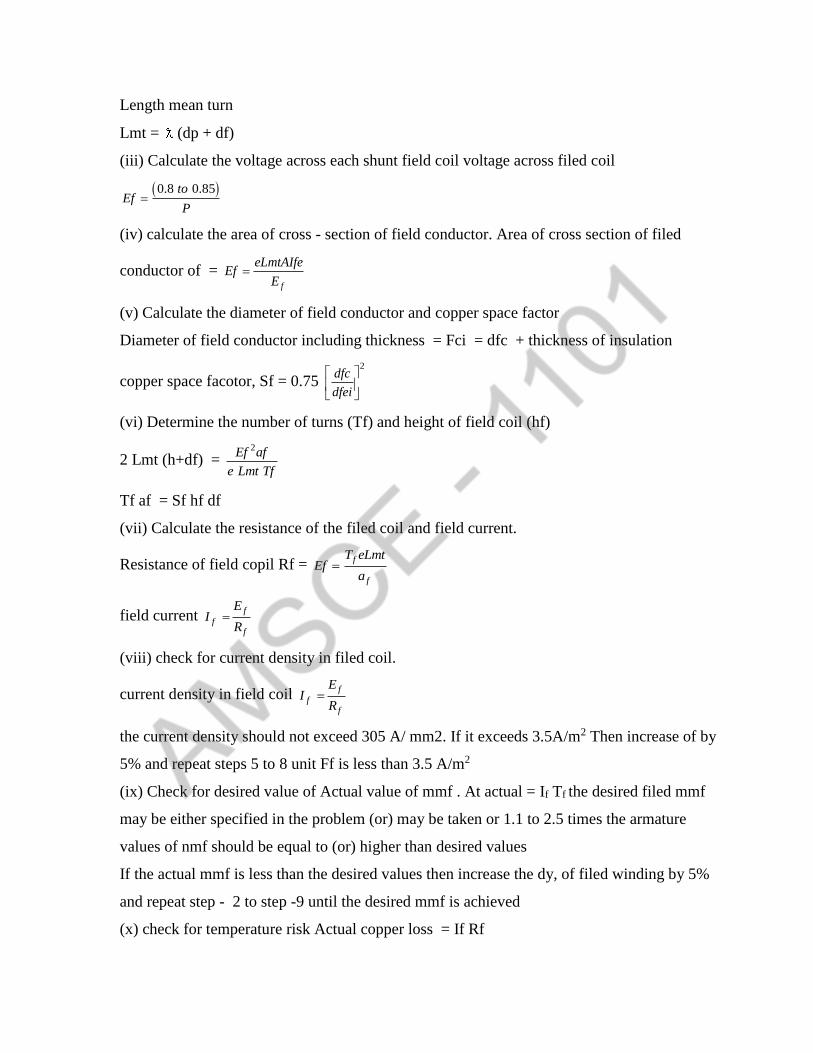
Length mean turn
Lmt = (dp + df)
(iii) Calculate the voltage across each shunt field coil voltage across filed coil
0.8 0.85toEf
P
(iv) calculate the area of cross - section of field conductor. Area of cross section of filed
conductor of = f
eLmtAIfeEf
E
(v) Calculate the diameter of field conductor and copper space factor
Diameter of field conductor including thickness = Fci = dfc + thickness of insulation
copper space facotor, Sf = 0.75 2
dfc
dfei
(vi) Determine the number of turns (Tf) and height of field coil (hf)
2 Lmt (h+df) = 2Ef af
e Lmt Tf
Tf af = Sf hf df
(vii) Calculate the resistance of the filed coil and field current.
Resistance of field copil Rf = f
f
T eLmtEf
a
field current f
ff
EI
R
(viii) check for current density in filed coil.
current density in field coil f
ff
EI
R
the current density should not exceed 305 A/ mm2. If it exceeds 3.5A/m2 Then increase of by
5% and repeat steps 5 to 8 unit Ff is less than 3.5 A/m2
(ix) Check for desired value of Actual value of mmf . At actual = If Tf the desired filed mmf
may be either specified in the problem (or) may be taken or 1.1 to 2.5 times the armature
values of nmf should be equal to (or) higher than desired values
If the actual mmf is less than the desired values then increase the dy, of filed winding by 5%
and repeat step - 2 to step -9 until the desired mmf is achieved
(x) check for temperature risk Actual copper loss = If Rf
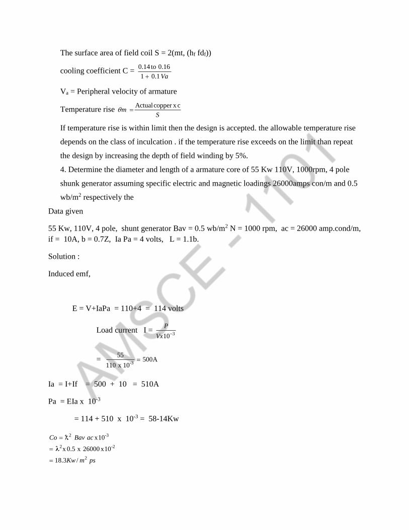
The surface area of field coil S = 2(mt, (hf fdf))
cooling coefficient C = 0.14 to 0.16
1 0.1 Va
Va = Peripheral velocity of armature
Temperature rise Actualcopper x c
mS
If temperature rise is within limit then the design is accepted. the allowable temperature rise
depends on the class of inculcation . if the temperature rise exceeds on the limit than repeat
the design by increasing the depth of field winding by 5%.
4. Determine the diameter and length of a armature core of 55 Kw 110V, 1000rpm, 4 pole
shunk generator assuming specific electric and magnetic loadings 26000amps con/m and 0.5
wb/m2 respectively the
Data given
55 Kw, 110V, 4 pole, shunt generator Bav = 0.5 wb/m2 N = 1000 rpm, ac = 26000 amp.cond/m,
if = 10A, b = 0.7Z, Ia Pa = 4 volts, L = 1.1b.
Solution :
Induced emf,
E = V+IaPa = 110+4 = 114 volts
Load current I = 310
P
Vx
= -3
55500A
110 x 10
Ia = I+If = 500 + 10 = 510A
Pa = EIa x 10-3
= 114 + 510 x 10-3 = 58-14Kw
2 -3
2 -2
2
x10
x 0.5 x 26000 x10
18.3 /
Co Bav ac
Kw m ps

Power developed in amateur Pa = CoD2Ln
2
3
2
58.14
128.3x 1000 / 60
0.0272
1.1b. b= 0.7
1.1b 1.1 0.7 0.77
0.77 x
0.72 x0.6048
4
0.6048 . 0.0272
PaD L
Con
m
L
L
P
D D
L D D L
D2 (0.6048 D)=0.0272
1/30.0272
D 0.3560.6048
m
L = 0.6048D = 0.6048 x 0.356 = 0.215m
The armature current , Ia = 510A
If wav winding is used turn
Current per parallel palm = Ia/2
Hence Lap winding is used,
Specific magnetic loading Bav = P
DL
Flux pa pole = Bav DL
P
= 0.5 0.355 0.215
4
= 0.03wb
Lap winding is used 2
E60
w
Number of armature conditions 2 = 60
N
E
60 114
2280.03 1000
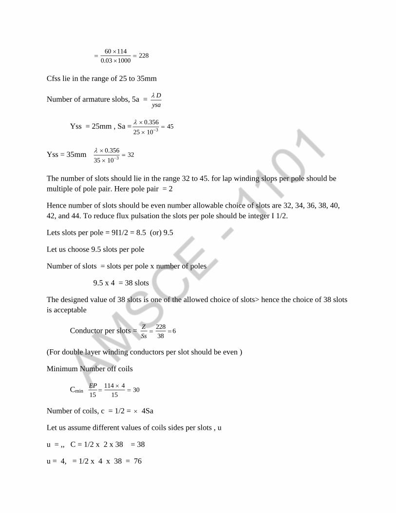
Cfss lie in the range of 25 to 35mm
Number of armature slobs, 5a = D
ysa
Yss = 25mm , Sa =3
0.35645
25 10
Yss = 35mm 3
0.35632
35 10
The number of slots should lie in the range 32 to 45. for lap winding slops per pole should be
multiple of pole pair. Here pole pair = 2
Hence number of slots should be even number allowable choice of slots are 32, 34, 36, 38, 40,
42, and 44. To reduce flux pulsation the slots per pole should be integer I 1/2.
Lets slots per pole = 9I1/2 = 8.5 (or) 9.5
Let us choose 9.5 slots per pole
Number of slots = slots per pole x number of poles
9.5 x 4 = 38 slots
The designed value of 38 slots is one of the allowed choice of slots> hence the choice of 38 slots
is acceptable
Conductor per slots = 228
638
Z
Ss
(For double layer winding conductors per slot should be even )
Minimum Number off coils
Cmin 114 4
3015 15
EP
Number of coils, c = 1/2 = 4Sa
Let us assume different values of coils sides per slots , u
u = ,, C = 1/2 x 2 x 38 = 38
u = 4, = 1/2 x 4 x 38 = 76

Choose the number of coils such that the conductor per slots is divisible by coils sides per slots.
Here to is divisible by 2. Hence the best choice for number of coils is 38
Solution:
Number of slots = 38
Number of coils = 38
Conductors per slots = 6
Total armature conductors
Z = slots x conductors /slots
= 38 x 6 == 228
Number of turn per coils = 2 228
32 2x38c
D = 0.356m
L = 0.215m
Sa = 38
C = 38
Z = 228
Conductors /slots = 6
Turn /coil = 3
5. A5KW 250 Voltas and pole 1500pm dc shunt generators is designed to have a square pole
face. The average magnetic flux density in the air gap is 0.42 wb/m2 and ampere conductors per
meter = 15000. Compute the main dimension of the machine. Assume full load efficiency =
87%. The repair of pole are to pole pitch = 0.06 [May/June 2015]
Data given:
5Kw, 250V , 4pole, N = 1500vpm Bav = 0.42wb/m2,ac = 15000 amp cad/m D =
87% L/T = 0.06
Solution:

Power developed in armature = Pa = 5
8.740.87
pKw
Output coefficient = Co = 2 Bw ac x 10-3
Co = 2 30.42 15000 10
= 62.178 KW/m2-rps
Pa = Co D2LA
2 5.74 5.74D L=
62.178 1500 / 60 1554.45
Pa
Co
= 0.00369
L/C = 0.06
L = 0.06
0.06
0.06 0.0471D4
PD
P
D2L = 0.00369
D2 [0.0471D] = 0.00369
0.0471D3 = 0.00369
0.00369
D 0.427890.471
m
L = 0.0471 x 0.4278 = 0.0201m
6 .Out put equation of a D.C machine
Induced emf in armature = E = 2
x60
N P
a
2
EP
a
In the armature of d.c machine the conductors are connected in parallel paths then the
currnt through each conuctors Iz = Ia
Ia aIza

Specific magnetic loading = Bav = P
DC
P = Bav x DL
Specific electric loading
2I Zac
D
2I Z = ac x D
power developed in armature Pa = EIa x 10-3 Kw
-32x Ia x10 Kw
ApPa
a
-32x I 2 x10 Kw
Ap
a
= I2 Z P x 10-3 kw
= 2I ZBw x x10-3KwDL
= -3x n x10ac Bav DL kw
2 2 3L 10D ac Bav Kw
2 3 210Bav ac Kw D L
co D2Ln
2 310Co Bavac
Co = output coefficient
7. Calculate the diameter and length of armature for 7.5KW 4 pole 1000rpm, 220V shunt motor.
Given full load efficiency =0 83 maximum gap flux density = 0.9 wb/m2. Specific electric
loading = 30.000 ampere conductor/metric field fam factor = 0.7. Assume that the maximum
efficiency occurs at full load and the field current is 2.5% of raped current the pole is square.
[May 2013]
Data Given:
Po = 7.5Kw, P = 4 n == 1000rpm V =- 220v, = 0.82 , Bg = 0.9wb/m2
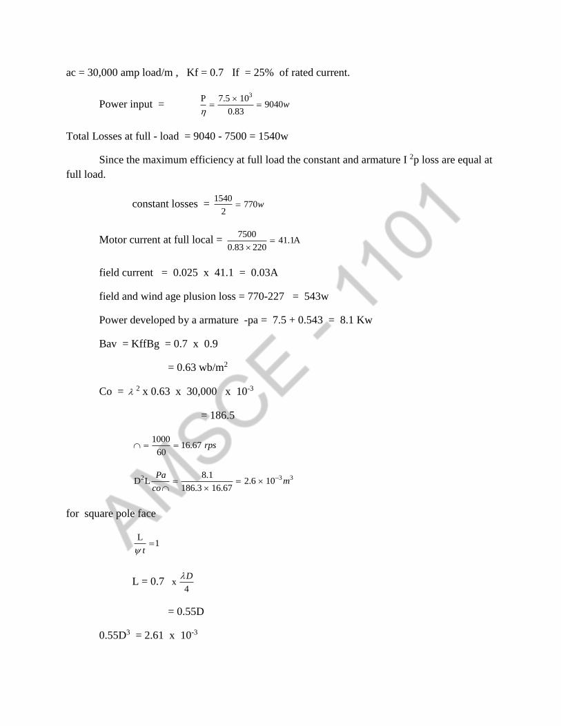
ac = 30,000 amp load/m , Kf = 0.7 If = 25% of rated current.
Power input = 3P 7.5 10
90400.83
w
Total Losses at full - load = 9040 - 7500 = 1540w
Since the maximum efficiency at full load the constant and armature I 2p loss are equal at
full load.
constant losses = 1540
7702
w
Motor current at full local = 7500
41.1A0.83 220
field current = 0.025 x 41.1 = 0.03A
field and wind age plusion loss = 770-227 = 543w
Power developed by a armature -pa = 7.5 + 0.543 = 8.1 Kw
Bav = KffBg = 0.7 x 0.9
= 0.63 wb/m2
Co = 2 x 0.63 x 30,000 x 10-3
= 186.5
1000
16.6760
rps
2 3 38.1D L 2.6 10
186.3 16.67
Pam
co
for square pole face
L
1t
L = 0.7 x4
D
= 0.55D
0.55D3 = 2.61 x 10⁻³
D = 0.17m
L= 0.09m
8. Explain various steps involved in the design of armature winding of DC machine [May -
2014]
Steps for design of lap winding for a dc machine
(i) find te range of slots form the RANGE OF SLOTS PITCH. armature slots pitch YSA
= 25 to 35mm. slots, sa = D /ysa , where D is diameter of armature.
(ii) In the above range of clots, list the values of slots which are multiples of pole pairs.
(iii) In order to reduce thus pulsations, the slots per pole should be an integer I Y2 the
integer should be in the range of 8 to 16 list all the multiples of integer 1/2 from the list obtained
in step 2
(iv) Choose the suitable slots from the list obtained in step 3
(v) Estimate the total number of armature conductor, Z using the equation of induced
emf,m E = 2n p/a. Find the conductors per slots and choose in to the nearest even number.
Conductors per slots = 2/w
(vi) Find the minimum number of coils Ep/15
(vii) Assume , u = 2,4,6,8,…..act where u = coils sides per slots
(viii) For each value of u calculate the number omf coils, C= = 1/2, S, choose the number
of coils such that it is greater than minimum number of coils. Also the values of u corresponding
to choose values of C should be a division of conductors per slots
(ix) Once the number of coils and slots are finalised. estimate the new values of odd
number of conductors and number of turns per coil. Total armature conductors, 2 = slots x
conductors per slots number of turn per coil = 2/2c
If a suitable value of c is slots obtained to satisfy the above conditions. then make another
choice of slots from the list obtained in step 3.
9. Find the minimum number of poles for a 1200 Kw generator if the arrange voltage between
Commutator systems is not to exceed 15 and the armature mmf per pole is not be exceed
10,000A.
Solution:
For simplex lap (or) wave winding, average voltage between adjacent segments
EP
EcC
Voltage of , machine C EP
EC
Taking single turn coil total number of coils in the machine
2
2 2
Z EcC E
P
P = EIa x 10-3 Kw = 2
Z Ec
pIa x 10-3
armature mmf paer pole .2
Ia ZATa
a p
AT2
IaZa a
p
P = aATa Ec x 10-3
Minimum number of paralel path = a 3x 10P
ATaEa
31200 10
810,000 15
These parallel paths can be obtained by using a simplex lap winding with poles
Minimum number of poles = 8
10. Design of Interpoles
The interpoles are small poles placed between main poles. The polarity of the main pole
just ahead for a generator and just behind it for a motor in the direction of rotation
The winding of the interpole must produce an mmf which is sufficient to naturalize the
cross magnetizing armature mmf of interpoler axis and enough more to produce the flux density
requried to generate rotational voltage in the coil undergoing commutation to cancle the
reactance voltage.
Since both the armature reaction and reactance voltage are proportional to armature current the
interpole winding should be connected in series with the armature for production of rectaxtizing
effect at all condition of load.
Average reactance voltage in the coil = 2Tc ac Va >L
Tc = Turns per (oil)
ac = Specific electric loading
Va = Peripheral speed of armature
L = Length of armature
= Specific per menace
The inductance of a coil in armature = 2TcL2
The interpoles are made of
Normally the length of interpole is made equal to length of main pole.
Bgi = Flux dendity under inter pole
L
Bgi acLi
Lip = Length of inter pole
2
12 s
a c
LBgi I Z
LiP V T
Zs = conductor per slots
lgi = Length of air gap under the interpole
Kgi = Interpole gap contraction factors
Ati - mmf required for interpole
Ati = mmf required to establish zgi + mmf required to overcome armature reaction
mmf required to establish bgi = 80,000 bgi
2
mmf requried to 2
overcome amature withoutcompensation winding2
reaction
I
P
21 4
2
I Z
p
(with compensation winding)
Number of turns in interpole = ATi/ In

Current density in interpole winding = I = 2.5 to 4A/mm2
Area if cross section of interpole conductor = Ia / i