Unigraphics NX to NX 2 CAM Transition - narod.ru · PDF fileCourse Overview Class Standards...
200
Unigraphics NX to NX 2 CAM Transition Student Guide October 2003 MT11015 — Unigraphics NX 2
Transcript of Unigraphics NX to NX 2 CAM Transition - narod.ru · PDF fileCourse Overview Class Standards...
Unigraphics NX to NX 2CAM Transition
Student GuideOctober 2003
MT11015 — Unigraphics NX 2
Manual History
ManualRevision
UnigraphicsVersion
PublicationDate
Version 16.0 June 2000
Version 17.0 January 2001
Version 18.0 September 2001
Unigraphics NX September 2002
A Unigraphics NX 2 October 2003
This edition obsoletes all previous editions.
Proprietary and Restricted Rights Notices
The following proprietary and restricted rights notices apply.
Copyright
Proprietary right of Unigraphics Solutions, Inc., its subcontractors, orits suppliers are included in this software, in the data, documentation, orfirmware related thereto, and in information disclosed therein. Neither thissoftware, regardless of the form in which it exists, nor such data, information,or firmware may be used or disclosed to others for any purpose except asspecifically authorized in writing by Unigraphics Solutions, Inc. Recipient byaccepting this document or utilizing this software agrees that neither thisdocument nor the information disclosed herein nor any part thereof shall bereproduced or transferred to other documents or used or disclosed to othersfor manufacturing or any other purpose except as specifically authorized inwriting by Unigraphics Solutions, Inc.
Copyright © 2003 Electronic Data Systems Corporation. All Rights Reserved.
Restricted Rights Legend
The commercial computer software and related documentation are providedwith restricted rights. Use, duplication or disclosure by the U.S. Governmentis subject to the protections and restrictions as set forth in the UnigraphicsSolutions Inc. commercial license for the software and/or documentation
© EDSAll rights reserved.Printed in the United States of America.
2 CAM Transition — Student Guide

as prescribed in DOD FAR 227-7202-3(a), or for Civilian agencies, in FAR27.404(b)(2)(i), and any successor or similar regulation, as applicable.Unigraphics Solutions Inc., 10824 Hope Street, Cypress, CA 90630.
Warranties and Liabilities
All warranties and limitations thereof given by Unigraphics Solutions, Inc.are set forth in the license agreement under which the software and/ordocumentation were provided. Nothing contained within or implied by thelanguage of this document shall be considered to be a modification of suchwarranties.
The information and the software that are that are the subject of thisdocument are subject to change without notice and should not be consideredcommitments by Unigraphics Solutions, Inc. Unigraphics Solutions, Inc.assumes no responsibility for any errors that may be contained within thisdocument.
The software discussed within this document is furnished under separatelicense agreement and is subject to use only in accordance with the licensingterms and conditions contained therein.
Trademarks
EDS, the EDS logo, I-DEAS, UNIGRAPHICS SOLUTIONS, UNIGRAPHICS,GRIP, PARASOLID, UG, UG/..., UG Solutions, and iMAN are trademarksor registered trademarks of Electronic Data Systems Corporation or itssubsidiaries. All other logos or trademarks used herein are the propertyof their respective owners.
CAM Transition — Student Guide 3


Contents
Course Overview . . . . . . . . . . . . . . . . . . . . . . . . . . . . . . . . . . . . . . . . . . 9
Course Description . . . . . . . . . . . . . . . . . . . . . . . . . . . . . . . . . . . . . . . 9Objectives . . . . . . . . . . . . . . . . . . . . . . . . . . . . . . . . . . . . . . . . . . 11Student Responsibilities . . . . . . . . . . . . . . . . . . . . . . . . . . . . . . . 12
Class Standards for Unigraphics Part Files . . . . . . . . . . . . . . . . . . . . 13Class Part File Naming . . . . . . . . . . . . . . . . . . . . . . . . . . . . . . . . 13Layers and Categories . . . . . . . . . . . . . . . . . . . . . . . . . . . . . . . . . 14
How to Use This Manual . . . . . . . . . . . . . . . . . . . . . . . . . . . . . . . . . . 14Classroom System Information . . . . . . . . . . . . . . . . . . . . . . . . . . 16Toolbar Information . . . . . . . . . . . . . . . . . . . . . . . . . . . . . . . . . . . 17
Usability Enhancements . . . . . . . . . . . . . . . . . . . . . . . . . . . . . . . . . . 1-1
Dynamic MCS and RCS Support . . . . . . . . . . . . . . . . . . . . . . . . . . . . 1-2Palette Support . . . . . . . . . . . . . . . . . . . . . . . . . . . . . . . . . . . . . . 1-3Activity: Use of Palettes . . . . . . . . . . . . . . . . . . . . . . . . . . . . . . . 1-5Post Process Dialog . . . . . . . . . . . . . . . . . . . . . . . . . . . . . . . . . . 1-10Dialog items outside of a Property Page . . . . . . . . . . . . . . . . . . . 1-11
Summary . . . . . . . . . . . . . . . . . . . . . . . . . . . . . . . . . . . . . . . . . . . . 1-12
Visualization Enhancements . . . . . . . . . . . . . . . . . . . . . . . . . . . . . . . 2-1
Replay Enhancements . . . . . . . . . . . . . . . . . . . . . . . . . . . . . . . . . . . 2-2Dynamic Material Removal Enhancements . . . . . . . . . . . . . . . . . 2-3
Summary . . . . . . . . . . . . . . . . . . . . . . . . . . . . . . . . . . . . . . . . . . . . . 2-4
General CAM Enhancements . . . . . . . . . . . . . . . . . . . . . . . . . . . . . . . 3-1
Creation of Ball Mill Milling Tools . . . . . . . . . . . . . . . . . . . . . . . . . . . 3-2Machine Coordinate System Purpose . . . . . . . . . . . . . . . . . . . . . . 3-4Operation Navigator . . . . . . . . . . . . . . . . . . . . . . . . . . . . . . . . . . 3-7Orientation of WCS to MCS . . . . . . . . . . . . . . . . . . . . . . . . . . . . . 3-8Spindle Output . . . . . . . . . . . . . . . . . . . . . . . . . . . . . . . . . . . . . . 3-9Tool Holder Definition . . . . . . . . . . . . . . . . . . . . . . . . . . . . . . . . 3-10Tool Number Output . . . . . . . . . . . . . . . . . . . . . . . . . . . . . . . . . 3-13
Activity: Defining Tool Numbers at the Pocket, Tool and OperationLevel . . . . . . . . . . . . . . . . . . . . . . . . . . . . . . . . . . . . . . . . . . 3-14
Summary . . . . . . . . . . . . . . . . . . . . . . . . . . . . . . . . . . . . . . . . . . . . 3-18
©EDS, All Rights Reserved CAM Transition — Student Guide 5

Contents
Wire EDM Enhancements . . . . . . . . . . . . . . . . . . . . . . . . . . . . . . . . . 4-1
Multiple Boundary Selection . . . . . . . . . . . . . . . . . . . . . . . . . . . . . . . 4-2Summary . . . . . . . . . . . . . . . . . . . . . . . . . . . . . . . . . . . . . . . . . . . . . 4-3
General Milling Enhancements . . . . . . . . . . . . . . . . . . . . . . . . . . . . . 5-1
Automatic Wall Detection in Face Milling . . . . . . . . . . . . . . . . . . . . . 5-3Cut Area in Face Milling Operations . . . . . . . . . . . . . . . . . . . . . . 5-5Preselect Wall Geometry in Face Milling . . . . . . . . . . . . . . . . . . . 5-6Wall Stock and Wall Geometry in Face Milling . . . . . . . . . . . . . . . 5-7Corner Roughing . . . . . . . . . . . . . . . . . . . . . . . . . . . . . . . . . . . . 5-20Activity: Using Corner Roughing . . . . . . . . . . . . . . . . . . . . . . . . 5-21Extend at Edges . . . . . . . . . . . . . . . . . . . . . . . . . . . . . . . . . . . . 5-26Activity: Extend at Edges . . . . . . . . . . . . . . . . . . . . . . . . . . . . . 5-29IPW in Fixed Axis Milling . . . . . . . . . . . . . . . . . . . . . . . . . . . . . 5-40Output Tracking Point . . . . . . . . . . . . . . . . . . . . . . . . . . . . . . . . 5-41Text Engraving . . . . . . . . . . . . . . . . . . . . . . . . . . . . . . . . . . . . . 5-42Activity: Planar and Contour Text Engraving . . . . . . . . . . . . . . 5-44Toward Drive Projection Method . . . . . . . . . . . . . . . . . . . . . . . . 5-48Trochoidal Cut Pattern . . . . . . . . . . . . . . . . . . . . . . . . . . . . . . . 5-49Activity: Trochoidal Cut Pattern . . . . . . . . . . . . . . . . . . . . . . . . 5-51Zlevel Corner Finishing with Reference Tool . . . . . . . . . . . . . . . 5-57ZigZag 3D Stepover . . . . . . . . . . . . . . . . . . . . . . . . . . . . . . . . . . 5-602D Contact Contour . . . . . . . . . . . . . . . . . . . . . . . . . . . . . . . . . . 5-613D Contact Ouput . . . . . . . . . . . . . . . . . . . . . . . . . . . . . . . . . . . 5-65
Summary . . . . . . . . . . . . . . . . . . . . . . . . . . . . . . . . . . . . . . . . . . . . 5-66
Turning Enhancements . . . . . . . . . . . . . . . . . . . . . . . . . . . . . . . . . . . 6-1
A-Axis Tool Control . . . . . . . . . . . . . . . . . . . . . . . . . . . . . . . . . . . . . . 6-2B-Axis Tool Control . . . . . . . . . . . . . . . . . . . . . . . . . . . . . . . . . . . . . . 6-4Summary . . . . . . . . . . . . . . . . . . . . . . . . . . . . . . . . . . . . . . . . . . . . . 6-5
Hole Making Enhancements . . . . . . . . . . . . . . . . . . . . . . . . . . . . . . . 7-1
Alternate Groups of Operations . . . . . . . . . . . . . . . . . . . . . . . . . . . . . 7-2Cut Area . . . . . . . . . . . . . . . . . . . . . . . . . . . . . . . . . . . . . . . . . . . 7-3Feature Recognition . . . . . . . . . . . . . . . . . . . . . . . . . . . . . . . . . . 7-5Activity: Feature Recognition . . . . . . . . . . . . . . . . . . . . . . . . . . . 7-7Feature Status . . . . . . . . . . . . . . . . . . . . . . . . . . . . . . . . . . . . . 7-20Holder Types . . . . . . . . . . . . . . . . . . . . . . . . . . . . . . . . . . . . . . . 7-213D In Process Work Piece (IPW) . . . . . . . . . . . . . . . . . . . . . . . . 7-22Activity: Using the IPW in Hole Making . . . . . . . . . . . . . . . . . . 7-23Maximum Cut Depth and Extended Length . . . . . . . . . . . . . . . . 7-33Activity: Maximum Cut Depth and Extended Length . . . . . . . . . 7-34Multiple Selection . . . . . . . . . . . . . . . . . . . . . . . . . . . . . . . . . . . 7-44Inch and Metric Availability within Tool Query . . . . . . . . . . . . . 7-45
Summary . . . . . . . . . . . . . . . . . . . . . . . . . . . . . . . . . . . . . . . . . . . . 7-46
6 CAM Transition — Student Guide ©EDS, All Rights Reserved
Contents
Integration, Simulation and Verification Enhancements . . . . . . . . 8-1
Integration, Simulation and Verification Overview . . . . . . . . . . . . . . 8-2Visualize . . . . . . . . . . . . . . . . . . . . . . . . . . . . . . . . . . . . . . . . . . . 8-4Simulation . . . . . . . . . . . . . . . . . . . . . . . . . . . . . . . . . . . . . . . . . 8-5Advanced Simulation . . . . . . . . . . . . . . . . . . . . . . . . . . . . . . . . . 8-6Machine Tool Builder . . . . . . . . . . . . . . . . . . . . . . . . . . . . . . . . . 8-7Machine Tool Driver . . . . . . . . . . . . . . . . . . . . . . . . . . . . . . . . . . 8-8Setup Configurator . . . . . . . . . . . . . . . . . . . . . . . . . . . . . . . . . . 8-10
Summary . . . . . . . . . . . . . . . . . . . . . . . . . . . . . . . . . . . . . . . . . . . . 8-11
V18 to NX What’s New in CAM . . . . . . . . . . . . . . . . . . . . . . . . . . . . . A-1
CAM User Interface . . . . . . . . . . . . . . . . . . . . . . . . . . . . . . . . . . . . A-1General Milling Enhancements . . . . . . . . . . . . . . . . . . . . . . . . . . . . A-2Hole Making . . . . . . . . . . . . . . . . . . . . . . . . . . . . . . . . . . . . . . . . . . A-3Turning . . . . . . . . . . . . . . . . . . . . . . . . . . . . . . . . . . . . . . . . . . . . . A-4
©EDS, All Rights Reserved CAM Transition — Student Guide 7


Course Overview
Course Description
This class will acquaint you with the new features and functionality that areavailable in the Unigraphics NX 2 Manufacturing application.
This class is designed for the experienced Unigraphics CAM user and makesthe assumption that you are familiar with Unigraphics NX1 CAM featuresand functions.
The structure of the lessons in this class will give you a brief description ofthe new feature or function and may include an activity that shows thatfeature or function in detail.
Included in this course are the following lessons:
• Usability Enhancements
• Visualization Enhancements
©EDS, All Rights Reserved CAM Transition — Student Guide 9
Course Description
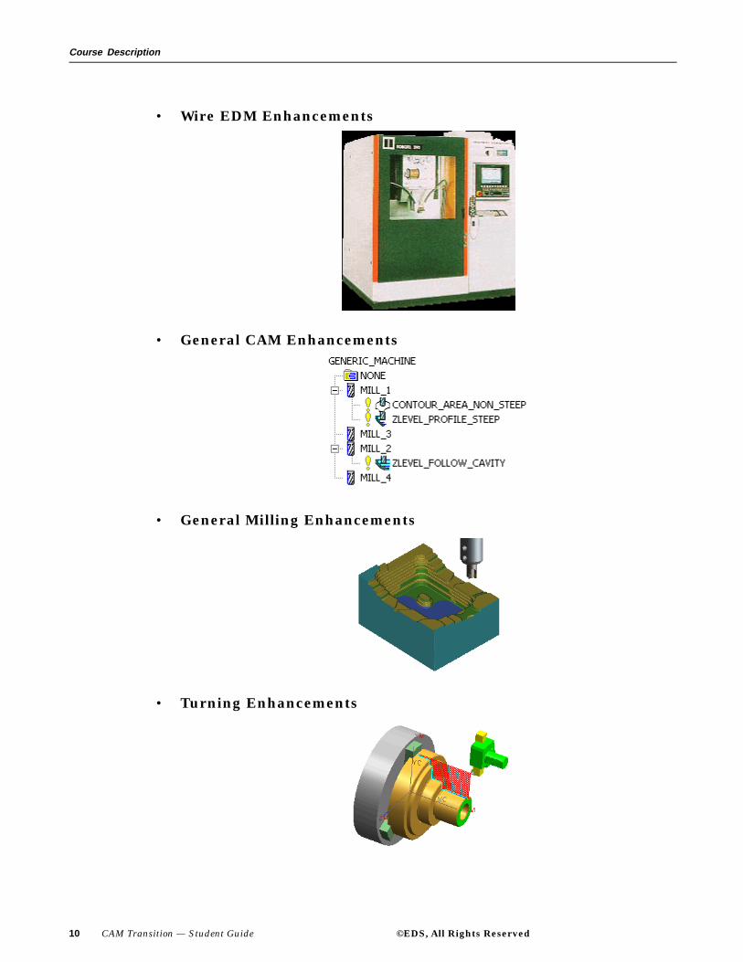
• Wire EDM Enhancements
• General CAM Enhancements
• General Milling Enhancements
• Turning Enhancements
10 CAM Transition — Student Guide ©EDS, All Rights Reserved
Course Overview
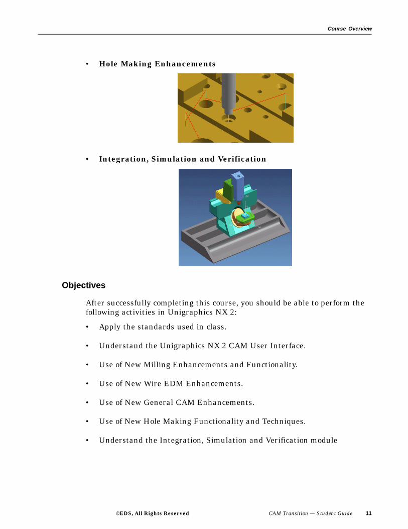
• Hole Making Enhancements
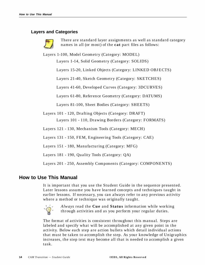
• Integration, Simulation and Verification
Objectives
After successfully completing this course, you should be able to perform thefollowing activities in Unigraphics NX 2:
• Apply the standards used in class.
• Understand the Unigraphics NX 2 CAM User Interface.
• Use of New Milling Enhancements and Functionality.
• Use of New Wire EDM Enhancements.
• Use of New General CAM Enhancements.
• Use of New Hole Making Functionality and Techniques.
• Understand the Integration, Simulation and Verification module
©EDS, All Rights Reserved CAM Transition — Student Guide 11

Course Description
Student Responsibilities
• Be on time.
• Participate in class.
• Stick with the subject matter.
• Listen attentively and take notes.
• Practice on the job what you have learned.
• Have Fun!
12 CAM Transition — Student Guide ©EDS, All Rights Reserved

Course Overview
Class Standards for Unigraphics Part Files
The following standards will be used in this class. Standardization allowsusers to work with others’ parts while being able to predict the organizationof the part file. All work should be performed in accordance with thesestandards.
Class Part File Naming
This class utilizes the following file naming standard:
When you are requested to save a part file for later use, or any time youwant to preserve work you have done, use the initials of your given name,middle name, and surname to replace the course identifier "cat" in the newfilename. The remainder of the filename should match the original. Thesefiles should reside in your home directory.
Currently up to 128 characters are allowed for file names, including4 characters for the .prt extension; thus, 124 characters areavailable for a descriptive name.
©EDS, All Rights Reserved CAM Transition — Student Guide 13
How to Use This Manual
Layers and Categories
There are standard layer assignments as well as standard categorynames in all (or most) of the cat part files as follows:
Layers 1-100, Model Geometry (Category: MODEL)
Layers 1-14, Solid Geometry (Category: SOLIDS)
Layers 15-20, Linked Objects (Category: LINKED OBJECTS)
Layers 21-40, Sketch Geometry (Category: SKETCHES)
Layers 41-60, Developed Curves (Category: 3DCURVES)
Layers 61-80, Reference Geometry (Category: DATUMS)
Layers 81-100, Sheet Bodies (Category: SHEETS)
Layers 101 - 120, Drafting Objects (Category: DRAFT)
Layers 101 - 110, Drawing Borders (Category: FORMATS)
Layers 121 - 130, Mechanism Tools (Category: MECH)
Layers 131 - 150, FEM, Engineering Tools (Category: CAE)
Layers 151 - 180, Manufacturing (Category: MFG)
Layers 181 - 190, Quality Tools (Category: QA)
Layers 201 - 250, Assembly Components (Category: COMPONENTS)
How to Use This ManualIt is important that you use the Student Guide in the sequence presented.Later lessons assume you have learned concepts and techniques taught inearlier lessons. If necessary, you can always refer to any previous activitywhere a method or technique was originally taught.
Always read the Cue and Status information while workingthrough activities and as you perform your regular duties.
The format of activities is consistent throughout this manual. Steps arelabeled and specify what will be accomplished at any given point in theactivity. Below each step are action bullets which detail individual actionsthat must be taken to accomplish the step. As your knowledge of Unigraphicsincreases, the step text may become all that is needed to accomplish a giventask.
14 CAM Transition — Student Guide ©EDS, All Rights Reserved

Course Overview
Step 1: This is an example of a step.
This is an example of an action bullet.
The general format for lesson content is:
• presentation
• activity
Most lessons have one or more activities.
• summary
For students who prefer more detail from an Instructor Led Course:
• ask questions
• confirm with restatement
• attend and pay attention to instruction as it is given.
Obviously, it is always necessary for students to consider the classroomsituation and be considerate of other students who may have greater or lesserneeds for instruction. Instructors cannot possibly meet the exact needs ofevery student.
At the start of each class day you will be expected to log onto your terminal,start Unigraphics, and to be ready to follow the instructor’s curriculum.At the end of the day’s class you should always quit Unigraphics and logoff the terminal.
©EDS, All Rights Reserved CAM Transition — Student Guide 15

How to Use This Manual
Classroom System Information
Your instructor will provide you with the following items forworking in the classroom:
Student Login:
User name:
Password:
Work Directory:
Parts Directory:
Instructor:
Date:
16 CAM Transition — Student Guide ©EDS, All Rights Reserved

Course Overview
Toolbar Information
This section will help you to assure that your computer displays toolbararrangements designed to match the instructions in this manual.
Step 1: If you have not already done so, use the classroom logininformation recorded on the previous page to log onto yourcomputer and start Unigraphics.
Step 2: Over any toolbar area, activate the mouse button 3 (MB3) popupmenu.
Step 3: From the MB3 menu, choose Customize...
Step 4: On the Options page choose Small (16x16) icons.
Step 5: On the Toolbar page choose Reset All.
This will cause all toolbars to update to configurations designedfor your class, or to the Unigraphics default for any toolbar nototherwise specified.
Step 6: Close the dialog, and await further direction from your instructor.
©EDS, All Rights Reserved CAM Transition — Student Guide 17

Lesson
1 Usability Enhancements
Purpose
The purpose of this lesson is to introduce the new functionality that pertainsto Usability of the CAM modules. These new features will make your CAMprogramming session easier to use, more meaningful and productive.
Objectives
In this lesson, you will learn about enhancements and functionality pertainingto CAM Usability of NX 2. New Usability enhancements pertains to:
• Dynamic MCS and RCS support.
• Palette Support.
• Post Process dialog.
• Dialog items outside of a Property Page.
©EDS, All Rights Reserved CAM Transition — Student Guide 1-1

Usability Enhancements
Dynamic MCS and RCS Support
When modifying the MCS or RCS you are now able to use dynamicinteraction, similar to the dynamic interaction of the WCS.
This is a quick and convenient way of orienting the MCS or RCS whileproviding instantaneous feedback.
1-2 CAM Transition — Student Guide ©EDS, All Rights Reserved
Usability Enhancements
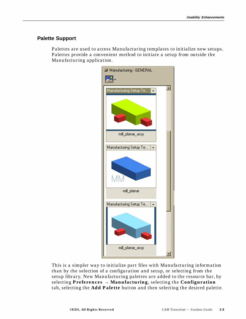
Palette Support
Palettes are used to access Manufacturing templates to initialize new setups.Palettes provide a convenient method to initiate a setup from outside theManufacturing application.
This is a simpler way to initialize part files with Manufacturing informationthan by the selection of a configuration and setup, or selecting from thesetup library. New Manufacturing palettes are added to the resource bar, byselecting Preferences → Manufacturing, selecting the Configurationtab, selecting the Add Palette button and then selecting the desired palette.
©EDS, All Rights Reserved CAM Transition — Student Guide 1-3

Usability Enhancements
The Manufacturing palette(s) will become available in the resource bar areawhen in Gateway, Modeling or Manufacturing.
1-4 CAM Transition — Student Guide ©EDS, All Rights Reserved

Usability Enhancements
Activity: Use of Palettes
In this activity you will add an inch palette to the Resource bar, initialize aCAM setup using the palette, verify that the palette is an assembly and willthen remove the palette from the Resource bar.
Step 1: Open the part cat_engrave_text.
If necessary, start Unigraphics NX 2.
Use File → Open.
Navigate to your parts folder and open the file.
For this example, you could use any part file that is in inch units.
Step 2: If necessary, enter the Manufacturing Application.
Choose Application → Manufacturing from the Menu bar.
Step 3: Add the inch palette to the Resource bar.
Choose Preferences → Manufacturing.
Choose the Configuration (1) tab.
Choose the Add Palette (2) button.
Choose Inch (3) from the Library Class Selection dialog.
©EDS, All Rights Reserved CAM Transition — Student Guide 1-5

Usability Enhancements
Choose OK to accept the Library Class Selection dialog.
Cancel the Manufacturing Preferences dialog.
1-6 CAM Transition — Student Guide ©EDS, All Rights Reserved

Usability Enhancements
The Manufacturing Inch tab now appears on the Resource bar.
Step 4: Initialize a CAM Setup using the Inch palette.
With a single step, you can now initialize a new CAM Setup, createan assembly using the part as a component of the assembly andthen enter the Manufacturing Application.
Open the part file cat_component.prt.
©EDS, All Rights Reserved CAM Transition — Student Guide 1-7

Usability Enhancements
Choose the Manufacturing-Inch tab from the Resourcebar and then choose the mill_planar_assy setup template.
A manufacturing assembly has been created.
Display the Assembly Navigator and note that the part is nowa component of the assembly.
A temporary name is assigned, you can save the assembly and givethe assembly a new name, then navigate to the directory of yourchoice and save the assembly which you have just created.
Step 5: Removing the palette from the Resource bar.
From the tool bar choose Preferences → Palettes.
Choose the Manufacturing-Inch palette and then choosethe Close icon.
1-8 CAM Transition — Student Guide ©EDS, All Rights Reserved

Usability Enhancements
Close the Palettes dialog.
Close the Part without saving.
This concludes the activity.
©EDS, All Rights Reserved CAM Transition — Student Guide 1-9

Usability Enhancements
Post Process Dialog
You may now browse in the Post Processor dialog for additional postprocessorswhich are not listed in the dialog list box. Selecting the BROWSE button willallow you to search directories for any postprocessor that was created withthe Post Builder (files with .pui extensions).
After selecting the postprocessor filename, the filename will appear in thelast position of the dialog list box.
Any postprocessor, inserted into the list box by this method, will be availablefor the current Unigraphics session, only. Exiting Unigraphics will removethose items from the list box.
1-10 CAM Transition — Student Guide ©EDS, All Rights Reserved

Usability Enhancements
Dialog items outside of a Property Page
When you customize a dialog you can now place items outside a propertypage. These items remain visible regardless of the property page you areviewing. If you have a button that needs to be available on all the propertypages in a dialog, you can now place them above or below the property pages.This saves you time in customizing the dialog as well as minimizing thedialogs overall size.
The following illustration shows Automatic Engage/Retract customizedoutside and to the top of the property page, available at all times.
©EDS, All Rights Reserved CAM Transition — Student Guide 1-11

Usability Enhancements
Summary
Ease of use is the key to being productive in the CAM programmingenvironment. New Usability functionality enhances your ability to createoperations and generate tool paths with increased productivity. In this lessonyou learned the following Usability productivity enhancements:
• The dynamic use of the MCS and RCS.
• Use of Palettes for setups and configuration.
• Browsing for a postprocessor from the Post Process dialog.
• Configuring items outside of a Property Page.
1-12 CAM Transition — Student Guide ©EDS, All Rights Reserved

Lesson
2 Visualization Enhancements
Purpose
Crucial to the making of error free programs is the ability to visualize toolpaths with your actual part. Key enhancements have been added to makethis function easier with the use of the IPW. This lesson will introduce you tothe latest Visualization enhancements that will increase your productivity.
Objectives
Upon completion of this lesson, you will become familiar with the newfunctionality and enhancements that pertains to visualization. Newvisualization enhancements are:
• Replay Enhancements
• Dynamic Material Removal Enhancements
©EDS, All Rights Reserved CAM Transition — Student Guide 2-1

Visualization Enhancements
Replay Enhancements
Two new filter types and a Pause at each level toggle have been addedto the Replay property page of the Tool Path Visualization dialog. TheWarnings filter will display only those motions for which warnings have beengenerated. The +/- n Motions filter displays the specified number of motionsforward and/or backward of the tool position. Pause at each level, whenplaying forward, stops the animation at the end of and beginning of each cutlevel when playing backward. Selecting Play Forward or Play Backwardwill continue the Replay motion. This toggle is active only if the Displayoption is set to Current Level.
2-2 CAM Transition — Student Guide ©EDS, All Rights Reserved

Visualization Enhancements
Dynamic Material Removal Enhancements
New toggles, Save IPW as component and Suppress Animation, havebeen added to the Dynamic property page of the Tool Path Visualizationdialog. Also, Use tool holder has been added to the IPW Collision CheckOptions dialog. When Save IPW as component is activated, a part file isgenerated for the IPW (in-process work piece) of each operation in which theIPW is stored as a faceted body. The facets are stored as a reference setcalled IPW in a location specified under Preferences → Manufacturing→ Configuration. You can use this part as blank geometry input tosubsequent operations. When Suppress Animation is activated, dynamicmaterial removal is performed without animation. The Next Operationanimation control button performs the material removal in the background.If the Generate IPW option is set to Fast, Normal, or Fine, the facetedbody is created when the material removal process has finished. When Usetool holder is turned on, the tool holder will be displayed during dynamicmaterial removal and will be used in conjunction with IPW collision checking.If the tool holder violates the material during a tool motion, a collision isdetected and will be reported.
©EDS, All Rights Reserved CAM Transition — Student Guide 2-3

Visualization Enhancements
Summary
Crucial to the making of error free programs is the ability to visualize toolpaths with your actual part. The ability to save the IPW as a component partand to use the tool holder for collision checking, allows you to detect errorsprior to postprocessing. In this lesson you learned:
• The new Replay enhancements.
• The new Dynamic Material Removal Enhancements.
2-4 CAM Transition — Student Guide ©EDS, All Rights Reserved
Lesson
3 General CAM Enhancements
Purpose
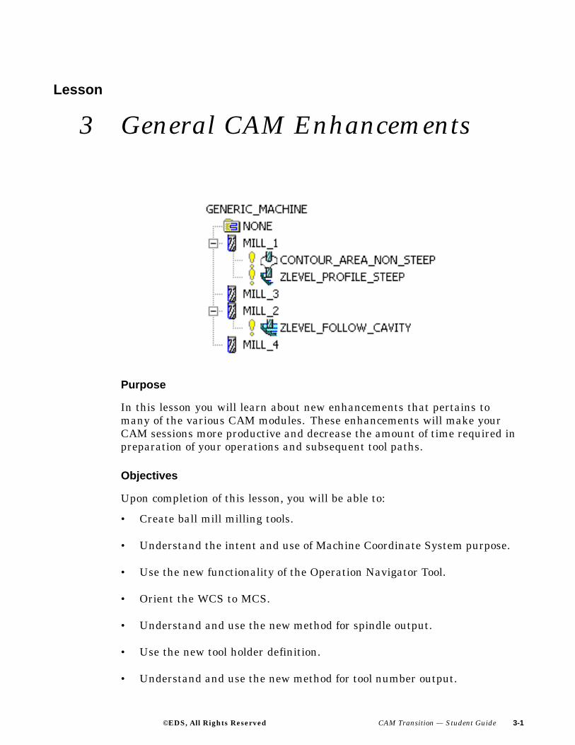
In this lesson you will learn about new enhancements that pertains tomany of the various CAM modules. These enhancements will make yourCAM sessions more productive and decrease the amount of time required inpreparation of your operations and subsequent tool paths.
Objectives
Upon completion of this lesson, you will be able to:
• Create ball mill milling tools.
• Understand the intent and use of Machine Coordinate System purpose.
• Use the new functionality of the Operation Navigator Tool.
• Orient the WCS to MCS.
• Understand and use the new method for spindle output.
• Use the new tool holder definition.
• Understand and use the new method for tool number output.
©EDS, All Rights Reserved CAM Transition — Student Guide 3-1

General CAM Enhancements
Creation of Ball Mill Milling Tools
The new icon for ball milling tools is now available from the create tooldialog when creating new milling tools. This tool subtype allows you to defineball mill cutting tools with or without a taper.
When using this option, you enter the actual ball diameter (1) and taperangle (2).
3-2 CAM Transition — Student Guide ©EDS, All Rights Reserved

General CAM Enhancements
Previously to create a ball milling tool, you calculated the theoreticaldiameter and corner radius of the actual tool.
©EDS, All Rights Reserved CAM Transition — Student Guide 3-3

General CAM Enhancements
Machine Coordinate System Purpose
This enhancement allows you to specify the use of the Machine CoordinateSystem (MCS) as it affects postprocessed output. The designation andinformation concerning the coordinate system(s) will be passed to thepostprocessor. The MCS is specified in an orientation group and can bedesignated as either a Main or Local coordinate system (purpose).
3-4 CAM Transition — Student Guide ©EDS, All Rights Reserved

General CAM Enhancements
If Local is designated as the coordinate system, you may specify one of thefollowing Special Output options (default is Fixture Offset):
• None
• Use Main MCS
• Fixture Offset
• CSYS Rotation
©EDS, All Rights Reserved CAM Transition — Student Guide 3-5

General CAM Enhancements
For pre-Unigraphics NX 2 parts, the MCS defaults to the Local designation.The Main designation sets the MCS as the machine’s Absolute CoordinateSystem. You can then use other MCS’s with fixture offsets to establishlocal coordinate systems such as G54. The postprocessor can also use therelationship between the Main and Local coordinate systems to definefixture offsets. These options are only available through customizing theMILL_ORIENT dialog through the addition of the Coordinate SystemPurpose and Special Output items.
3-6 CAM Transition — Student Guide ©EDS, All Rights Reserved

General CAM Enhancements
Operation Navigator
You can now display the Tool Number in a column in the Program and ToolViews of the Operation Navigator. In the Tool View, you can display the tools,without the hierarchy of carriers and pockets. You would use this option tosee the Tool Number that would be passed to the postprocessor or CLSF.You can also use this option to eliminate the display of information that is notrelevant to your machine tool or postprocessor. Display of the Tool Numbercolumn in the Operation Navigator is controlled by using MB3 → Columnsand then selecting Tool Number.
The Tool View display is changed in the background of the OperationNavigator with MB3 → Properties → Condensed Tool View.
©EDS, All Rights Reserved CAM Transition — Student Guide 3-7

General CAM Enhancements
Orientation of WCS to MCS
Orient WCS to MCS allows the WCS to position and orient to the operationor group object when either is edited. This is a new toggle button that can befound in the Manufacturing Preferences dialog. When editing milling,drilling or hole making operations, Orient WCS to MCS will place theWCS at the active MCS. The active MCS for any single operation will be theMCS defined in the parent Mill Orient Geometry Group of the operationbeing edited.
In turning operations, there are occasions when it is not always possible toorient the WCS to the MCS. Save WCS Orientation has been added to theMCS_SPINDLE dialog for such cases.
This option is selected whenever the preference Orient WCS to MCS isactivated. It does not create a CSYS, but does record the coordinate systeminformation within the group object. If there are no saved orientations in theTurn Orient Group, the WCS will be oriented to the MCS specified in thegroup if the Orient WCS to MCS preference is turned on.
3-8 CAM Transition — Student Guide ©EDS, All Rights Reserved

General CAM Enhancements
Spindle Output
Previous to NX 2, the SPINDL/ machine control command and the Feedsand Speeds dialog were the only methods available to fully control thespindle. This procedure has been greatly simplified with spindle parametersnow defined interactively in the Feeds and Speeds dialog. Spindle andspeeds and feeds information is now stored as parameters within theoperation.
When you open a legacy part containing SPINDL/ post commands,the information from the command is moved to the operation Feedsand Speeds dialog with the corresponding UDE removed. CLSOutput generates the SPINDL/ post command based on the newoperation parameters.
©EDS, All Rights Reserved CAM Transition — Student Guide 3-9

General CAM Enhancements
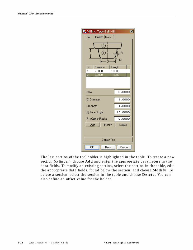
Tool Holder Definition
This enhancement allows you to define the approximate shape of the toolholder by a series of stacked cylinders. Each cylinder is defined by a diameter(1), length (2), taper angle (3) and bottom corner radius (4).
This feature is used when you need an accurate representation of the toolholder for processors that check the tool for collision avoidance (Area Milling,Flow Cut, Zlevel, and Hole Making). When creating a new tool, select theHolder property page in the Tool Definition dialog.
3-10 CAM Transition — Student Guide ©EDS, All Rights Reserved

General CAM Enhancements
For an existing tool, the tool holder can be added by customizing the dialogs.
As the cylinders are defined, they are stacked one on top of the other toform the holder.
©EDS, All Rights Reserved CAM Transition — Student Guide 3-11
General CAM Enhancements
The last section of the tool holder is highlighted in the table. To create a newsection (cylinder), choose Add and enter the appropriate parameters in thedata fields. To modify an existing section, select the section in the table, editthe appropriate data fields, found below the section, and choose Modify. Todelete a section, select the section in the table and choose Delete. You canalso define an offset value for the holder.
3-12 CAM Transition — Student Guide ©EDS, All Rights Reserved

General CAM Enhancements
Tool Number Output
Tool Numbers are now defined interactively and are no longer defined usingthe tool change UDE, LOAD/TOOL command. The new tool objects, ToolCarrier and Pocket, allow you to manage tool changes and determine thelevel at which the tool numbers are defined.
Tool Numbers can be defined at the pocket, tool, and operation level. ToolNumbers are inherited from pocket, to tool, to operation. Inheritance canbe overridden by defining the tool number within the operation. Dependingon your programming environment, you will need to determine whether itis appropriate to define the tool number at the pocket level, tool level orwithin an operation. Regardless of where you define the Tool Number, theoutput tool number is always displayed within the operation and in the ToolNumber column of the Operation Navigator.
©EDS, All Rights Reserved CAM Transition — Student Guide 3-13

General CAM Enhancements
Activity: Defining Tool Numbers at the Pocket, Tool and OperationLevel
In this activity you will define the Tool Number interactively at the Pocket,Tool and Operation level. This replaces the previous method of using theLOAD/TOOL UDE.
Step 1: Open the part cat_face_mill_tunnel.
If necessary, start Unigraphics NX 2.
Use File → Open.
Navigate to your parts folder and open the file.
Briefly examine the part.
Step 2: If necessary, enter the Manufacturing Application and displaythe Operation Navigator.
Choose Application → Manufacturing from the Menu bar.
Choose the Operation Navigator icon from the Resource
bar.
If necessary, change to the Program Order View of theOperation Navigator.
The operation FACE_MILLING is listed in the displaywindow.
Notice the Tool Number column heading and the tool numberdisplayed is 30.
Step 3: Examine the FACE_MILLING operation.
Change to the Machine Tool View of the OperationNavigator and expand all parent group objects.
3-14 CAM Transition — Student Guide ©EDS, All Rights Reserved

General CAM Enhancements
When this part was originally programmed, the tool numberwas assigned in the MCT_POCKET parent group object.
• Double-click on the MCT_POCKET parent group object.Notice the Pocket ID number is 30.
Tool Numbers can be defined at the pocket, tool andoperation level. Tool Numbers are inherited frompocket, to tool, to operation and can be overridden bydefining the Tool Number within the operation.
You will now modify the Tool Number and assign the numberto the tool holder.
Step 4: Change the Tool Number by modifying the tool parameters.
Choose OK on the Pocket: dialog.
Double-click on the MILL parent group object.
On the Milling Tool-5 Parameters dialog, change the ToolNumber to 27.
©EDS, All Rights Reserved CAM Transition — Student Guide 3-15

General CAM Enhancements
Choose OK.
Notice that the Tool Number, in the Tool Number columnof the Machine Tool view of the Operation Navigator changesto 27 from 30.
You may also change the Tool Number by editing theoperation.
Step 5: Change the tool number by modifying the operation.
Double-click on the FACE_MILLING operation.
Choose the Machine button.
Change the Tool Number from 27 to 11.
3-16 CAM Transition — Student Guide ©EDS, All Rights Reserved

General CAM Enhancements
Choose OK on the Machine Control dialog.
Choose OK on the FACE_MILLING dialog.
Notice that the Tool Number, in the Tool Number column ofthe Machine Tool view on the Operation Navigator changes to11 in the FACE_MILLING operation only, and that the parentgroup object MILL still retains the number 27.
Close the part file, without saving.
This concludes the activity.
©EDS, All Rights Reserved CAM Transition — Student Guide 3-17

General CAM Enhancements
Summary
The new general enhancements for NX 2 CAM greatly reduce the amountof time required for generating operations and subsequent tool paths. Thefollowing new enhancements and functionality were presented in this lesson:
• How to create ball mill milling tools.
• Use of the Machine Coordinate System purpose.
• Enhancements to the Operation Navigator Tool.
• How to perform Orientation of WCS to MCS.
• New method of achieving spindle output.
• New method of tool holder definition.
• New method of achieving tool number output.
3-18 CAM Transition — Student Guide ©EDS, All Rights Reserved
Lesson
4 Wire EDM Enhancements
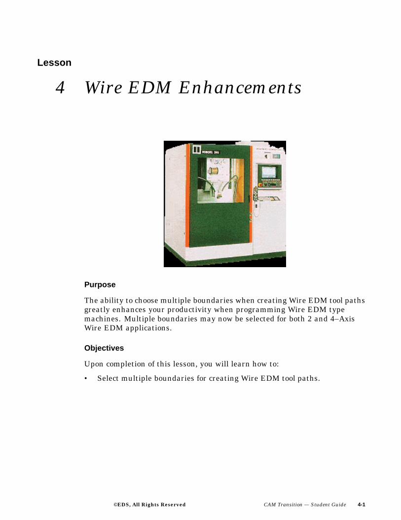
Purpose
The ability to choose multiple boundaries when creating Wire EDM tool pathsgreatly enhances your productivity when programming Wire EDM typemachines. Multiple boundaries may now be selected for both 2 and 4–AxisWire EDM applications.
Objectives
Upon completion of this lesson, you will learn how to:
• Select multiple boundaries for creating Wire EDM tool paths.
©EDS, All Rights Reserved CAM Transition — Student Guide 4-1

Wire EDM Enhancements
Multiple Boundary Selection
You may now select multiple boundaries when creating wire EDM tool paths.Geometry dialogs now provide icons allowing the selection of geometry fortwo and four axis applications.
• Two Axis Wire EDM
• Four Axis Wire EDM
Two Axis Wire EDM boundaries can be created from face, curve and pointboundaries.
Four Axis Wire EDM boundaries can be created from top face, side face aswell as curve and point boundaries.
4-2 CAM Transition — Student Guide ©EDS, All Rights Reserved

Wire EDM Enhancements
Summary
In this lesson you learned:
• That you can select multiple boundaries for two and four axis WireEDM applications.
©EDS, All Rights Reserved CAM Transition — Student Guide 4-3

Lesson
5 General Milling Enhancements
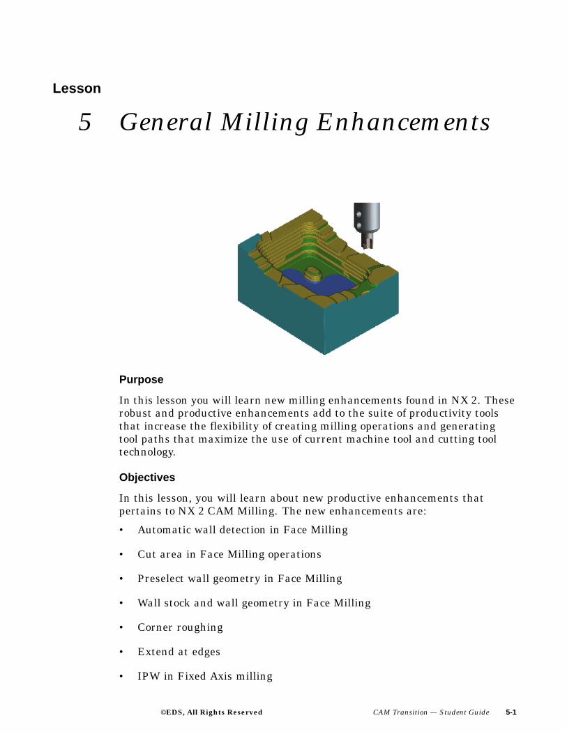
Purpose
In this lesson you will learn new milling enhancements found in NX 2. Theserobust and productive enhancements add to the suite of productivity toolsthat increase the flexibility of creating milling operations and generatingtool paths that maximize the use of current machine tool and cutting tooltechnology.
Objectives
In this lesson, you will learn about new productive enhancements thatpertains to NX 2 CAM Milling. The new enhancements are:
• Automatic wall detection in Face Milling
• Cut area in Face Milling operations
• Preselect wall geometry in Face Milling
• Wall stock and wall geometry in Face Milling
• Corner roughing
• Extend at edges
• IPW in Fixed Axis milling
©EDS, All Rights Reserved CAM Transition — Student Guide 5-1

General Milling Enhancements
• Output tracking point
• Text engraving
• Toward drive projection method
• Trochoidal cut pattern
• Zlevel Corner finishing with reference tool
• ZigZag 3D stepover
• 2D Contact Contour
• 3D Contact Output
5-2 CAM Transition — Student Guide ©EDS, All Rights Reserved

General Milling Enhancements
Automatic Wall Detection in Face Milling
Automatic Wall detection allows Face Milling operations to recognize andapply wall stock to faces that are adjacent to selected Cut Area faces.
For each face/floor in the Cut Area, the walls will start with faces that areadjacent to the floor (bottom red dot) and that form a concave angle or curveupwards, relative to the material side of the floor. The walls will continueupward, including faces that are tangent, concave or slightly convex. Thewalls will stop (top red dot) once a concave face is encountered or when aconvex face does not satisfy angular tolerance criteria.
©EDS, All Rights Reserved CAM Transition — Student Guide 5-3

General Milling Enhancements
Automatic Wall Rules: In cases 4 and 8, Automatic Wall stops at thefirst concave face beyond the face adjacent to the floor. In cases 3 and 5,Automatic Wall stops at the first convex face beyond the face adjacent tothe floor that is outside the angular tolerance. In case 3, the first convexface lies within the angular tolerance so the wall is extended upwards untilit encounters the next convex face that lies outside the angular tolerance.In case 5, the wall stops at the first convex face since that face lies outsidethe angular tolerance.
Automatic Wall Limitations: Automatic Wall detection will not applyif Face Geometry (blank boundaries) are used to define the blankcontainment. In cases where the wall faces extend below the Cut Area floorface(s), Automatic Wall may select more wall faces than are appropriate.In these cases you will need to select the wall geometry manually.
5-4 CAM Transition — Student Guide ©EDS, All Rights Reserved
General Milling Enhancements
Cut Area in Face Milling Operations
You can now use Cut Area, in addition to Face Geometry (blankboundaries) to define the blank containment for a Face Milling operation.Both of these options are mutually exclusive of one another. You will be ableto use Face Geometry or Cut Area to define blank containment, but notboth. Using Cut Area for blank containment will also allow you to defineWall Geometry for the Face Milling operation. If Face Geometry is usedfor containment, selection of Wall Geometry is not permissible.
There are two separate methods that you may use to generate a Face Millingoperation. The first method Boundary Approach, uses Face Geometry(blank boundaries) for blank containment. Wall Geometry cannot bedefined. The second method, Geometry Approach, uses Cut Area faces forblank containment. Wall Geometry may be defined by this method.
Other differences between using Face Geometry and Cut Area includethe following:
• Unlike Face Geometry, Cut Area will not place any limitation on thetypes of faces that are selected. Tool paths are generated only for CutArea faces that are flat and normal to the tool axis. Cut Area facesthat are not flat or normal to the tool axis will be treated the same aspart geometry.
• In order to generate tool paths for the Cut Area faces, Part geometrymust be defined with the Cut Area faces being a subset of the Partgeometry.
• The current Face Geometry dialog allows you to specify Ignore Holesand Ignore Chamfers when faces are selected. For Cut Area faces,Ignore Holes will be turned on and Ignore Chamfers will be turnedoff by default.
• The Face Geometry dialog allows you to insert a boundary into theexisting Blank Boundary list. For Cut Area, you are only allowedto append faces to the Cut Area.
• Cut Area will be processed in the same manner as Face Geometry.Blank Stock will be applied to the Cut Area faces using the samemethod as applied to Face Geometry.
©EDS, All Rights Reserved CAM Transition — Student Guide 5-5

General Milling Enhancements
Preselect Wall Geometry in Face Milling
In addition to Automatic Wall selection, you also have the option toPre-Select Wall Geometry based upon the Cut Area faces.
Wall faces extracted via the Cut Area faces will be appended to the WallGeometry. The Pre-Select option utilizes the same algorithms to extractWall Geometry as the Automatic Wall identification option. The differencesbetween Automatic Wall identification and Wall Pre-Selection are:
• Pre-Select Wall Geometry allows you to edit, remove or append facesto Wall Geometry prior to tool path generation while Automatic Wallidentification does not.
• The Pre-Select option is associative. Any changes to the Wall Geometrysince the operation was last generated will automatically flag theoperation for update. Automatic Wall identification is not associative.
5-6 CAM Transition — Student Guide ©EDS, All Rights Reserved

General Milling Enhancements
Wall Stock and Wall Geometry in Face Milling
Face Milling now allows you to select Wall Geometry and specify WallStock.
This is useful when the walls have finishing requirements that are differentfrom the cut area faces. The Automatic Wall option allows the walls to bedetermined automatically based on the selected cut area faces. The wallsstart with faces that are adjacent to the cut area and form a concave anglerelative to the material side of the cut area faces. The walls continue upwardto include faces that are tangent, concave, or slightly convex. You may definethe cut area and wall geometry from within the Face Milling operation, orinherit them from a MILL_AREA geometry group.
©EDS, All Rights Reserved CAM Transition — Student Guide 5-7
General Milling Enhancements
Activity: Using Cut Area and Wall Stock in Face Milling
In this activity you will modify existing Face Milling operations tofamiliarize yourself with the new stock options found in Face Milling.
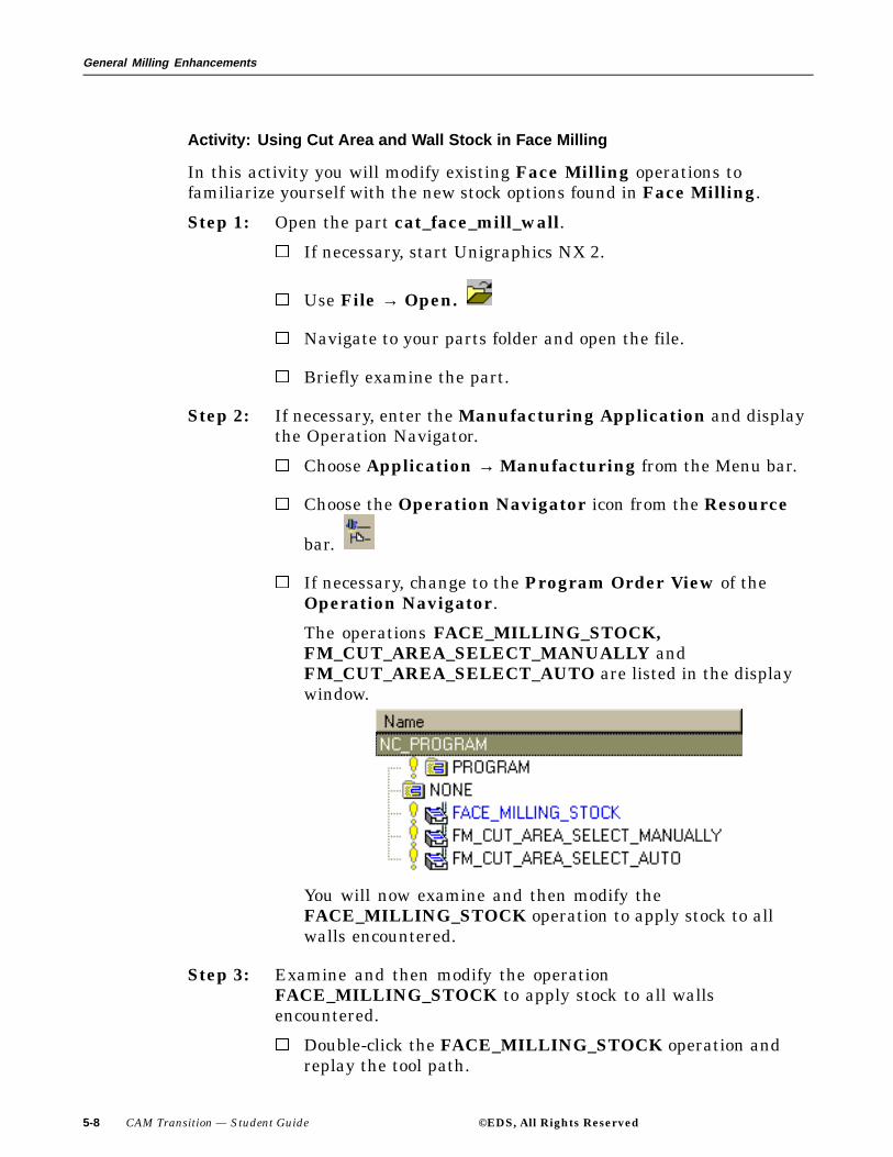
Step 1: Open the part cat_face_mill_wall.
If necessary, start Unigraphics NX 2.
Use File → Open.
Navigate to your parts folder and open the file.
Briefly examine the part.
Step 2: If necessary, enter the Manufacturing Application and displaythe Operation Navigator.
Choose Application → Manufacturing from the Menu bar.
Choose the Operation Navigator icon from the Resource
bar.
If necessary, change to the Program Order View of theOperation Navigator.
The operations FACE_MILLING_STOCK,FM_CUT_AREA_SELECT_MANUALLY andFM_CUT_AREA_SELECT_AUTO are listed in the displaywindow.
You will now examine and then modify theFACE_MILLING_STOCK operation to apply stock to allwalls encountered.
Step 3: Examine and then modify the operationFACE_MILLING_STOCK to apply stock to all wallsencountered.
Double-click the FACE_MILLING_STOCK operation andreplay the tool path.
5-8 CAM Transition — Student Guide ©EDS, All Rights Reserved

General Milling Enhancements
Note how the tool path is adjacent to all walls. You will nowadd 10 mm. of stock to all walls that are encountered.
©EDS, All Rights Reserved CAM Transition — Student Guide 5-9
General Milling Enhancements
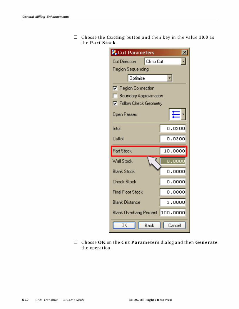
Choose the Cutting button and then key in the value 10.0 asthe Part Stock.
Choose OK on the Cut Parameters dialog and then Generatethe operation.
5-10 CAM Transition — Student Guide ©EDS, All Rights Reserved

General Milling Enhancements
Notice how the tool stays away from all walls. Uniform partstock of 10mm was applied to all sides of the part.
You will now examine and modify an operation that willrequire manual selection of the walls, using Cut Area as thecontainment method.
Step 4: Use Cut Area as the containment method and manually selectthe Wall Geometry.
You will first select the Cut Area and then the Wall Geometrythat stock will be applied too.
Double-click the FM_CUT_AREA_SELECT_MANUALLYoperation.
Choose the Cut Area icon and then Select.
©EDS, All Rights Reserved CAM Transition — Student Guide 5-11
General Milling Enhancements
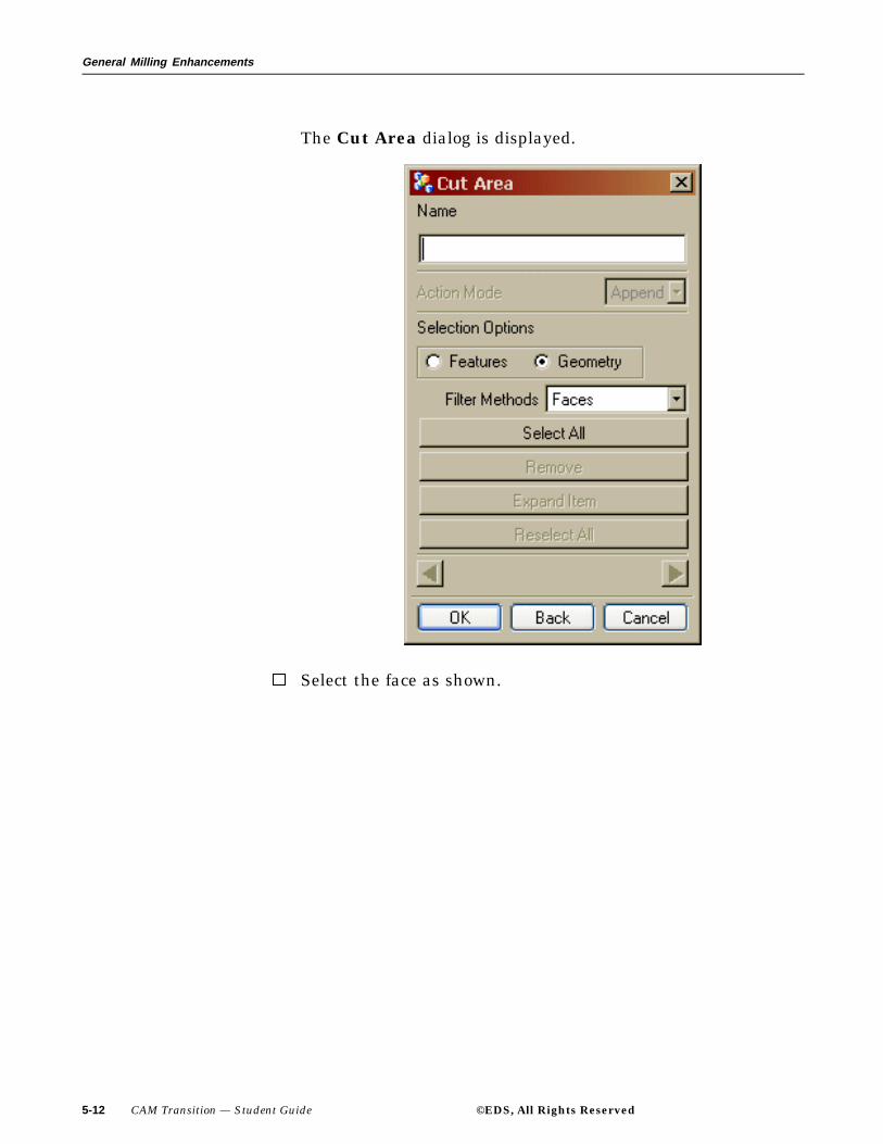
The Cut Area dialog is displayed.
Select the face as shown.
5-12 CAM Transition — Student Guide ©EDS, All Rights Reserved

General Milling Enhancements
Choose OK on the Cut Area dialog.
Choose the Wall Geometry icon and then Select.
The Wall Geometry dialog is displayed.
©EDS, All Rights Reserved CAM Transition — Student Guide 5-13

General Milling Enhancements
Select the walls as shown.
5-14 CAM Transition — Student Guide ©EDS, All Rights Reserved
General Milling Enhancements
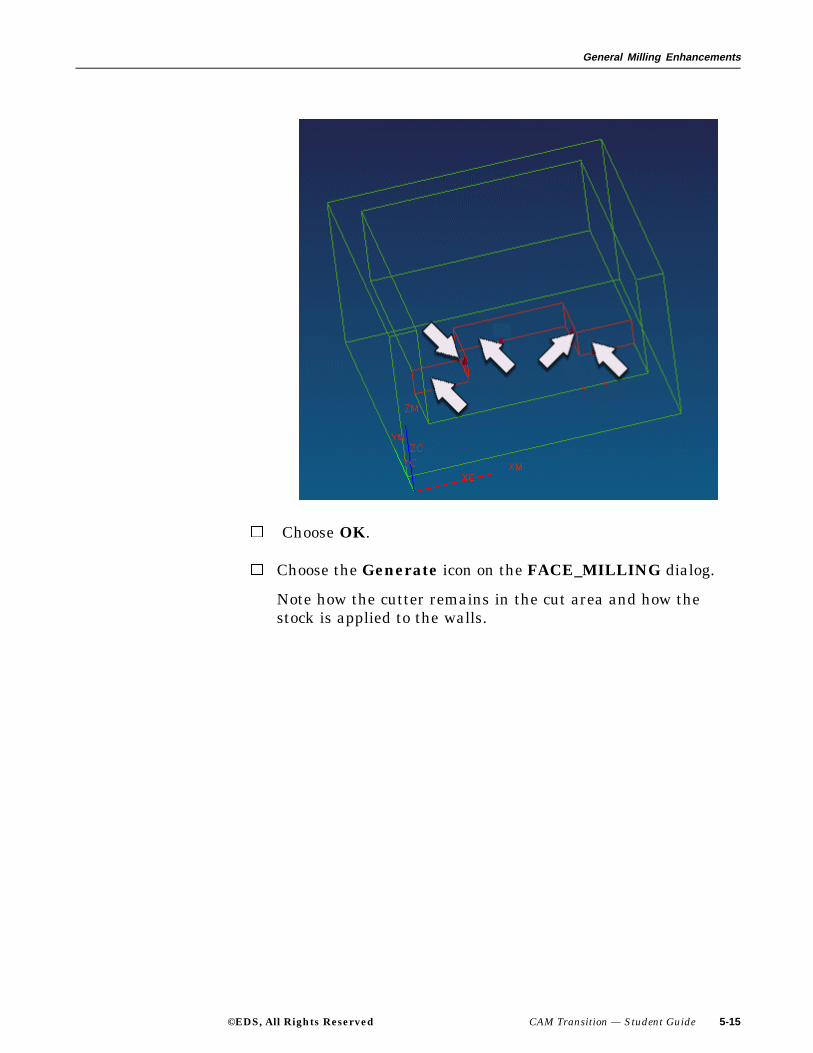
Choose OK.
Choose the Generate icon on the FACE_MILLING dialog.
Note how the cutter remains in the cut area and how thestock is applied to the walls.
©EDS, All Rights Reserved CAM Transition — Student Guide 5-15

General Milling Enhancements
You will edit an operation that will use Automatic WallDetection in the operation.
Step 5: Use Cut Area as the containment method and automaticallyselect the Wall Geometry.
The Cut Area has been previously selected.
Double-click the FM_CUT_AREA_SELECT_AUTOoperation.
Choose the Cut Area icon and then Display.
The Cut Area is displayed.
5-16 CAM Transition — Student Guide ©EDS, All Rights Reserved
General Milling Enhancements
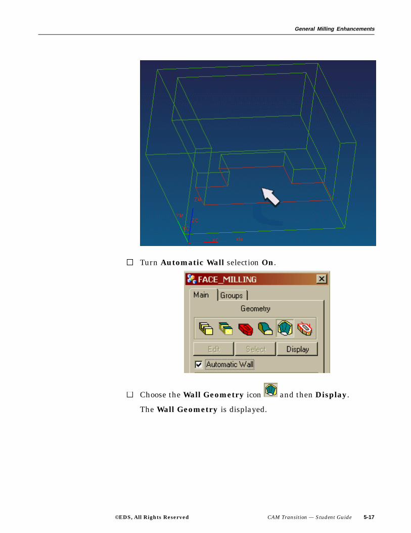
Turn Automatic Wall selection On.
Choose the Wall Geometry icon and then Display.
The Wall Geometry is displayed.
©EDS, All Rights Reserved CAM Transition — Student Guide 5-17

General Milling Enhancements
Choose the Generate icon on the FACE_MILLING dialog.
Note how the cutter remains in the cut area and how thestock is applied to the walls.
5-18 CAM Transition — Student Guide ©EDS, All Rights Reserved

General Milling Enhancements
Close the part file without saving.
This concludes the activity.
©EDS, All Rights Reserved CAM Transition — Student Guide 5-19
General Milling Enhancements
Corner Roughing
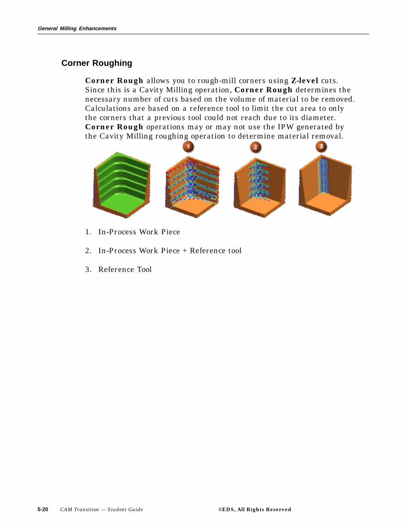
Corner Rough allows you to rough-mill corners using Z-level cuts.Since this is a Cavity Milling operation, Corner Rough determines thenecessary number of cuts based on the volume of material to be removed.Calculations are based on a reference tool to limit the cut area to onlythe corners that a previous tool could not reach due to its diameter.Corner Rough operations may or may not use the IPW generated bythe Cavity Milling roughing operation to determine material removal.
1. In-Process Work Piece
2. In-Process Work Piece + Reference tool
3. Reference Tool
5-20 CAM Transition — Student Guide ©EDS, All Rights Reserved

General Milling Enhancements
Activity: Using Corner Roughing
In this activity you will create a Corner Roughing operation utilizing theIPW as Blank Geometry.
Step 1: Open the part cat_corner_rough.
If necessary, start Unigraphics NX 2.
Use File → Open.
Navigate to your parts folder and open the file.
Briefly examine the part.
Step 2: If necessary, enter the Manufacturing Application and displaythe Operation Navigator.
Choose Application → Manufacturing from the Menu bar.
Choose the Operation Navigator icon from the Resource
bar.
If necessary, change to the Program Order View of theOperation Navigator.
You will now create a Corner Roughing operation that willuse the IPW to remove stock from the corners of the part.
Step 3: Create a Corner Rough operation utilizing the IPW as Blankgeometry.
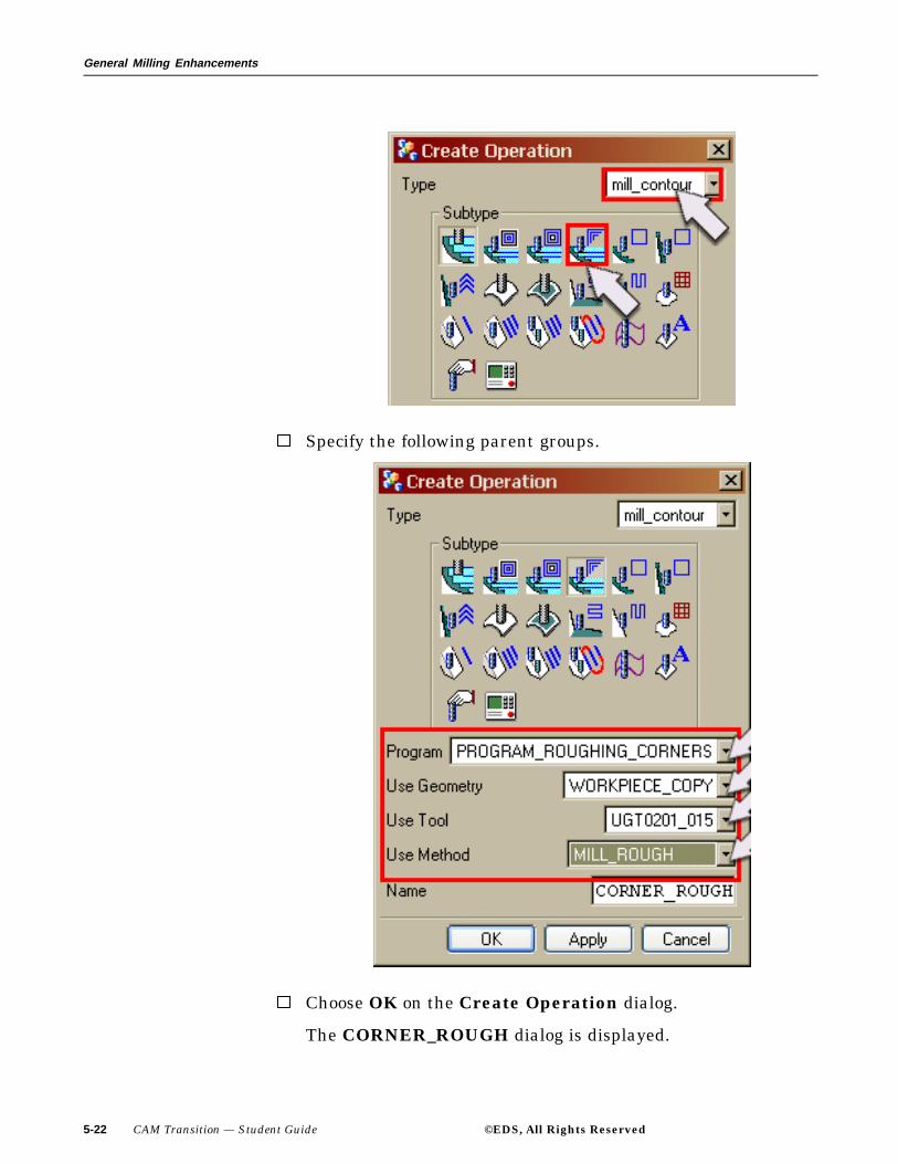
Choose the Create Operation icon.
If necessary, choose the Type as mill_contour and thenchoose the CORNER_ROUGH operation type.
©EDS, All Rights Reserved CAM Transition — Student Guide 5-21
General Milling Enhancements
Specify the following parent groups.
Choose OK on the Create Operation dialog.
The CORNER_ROUGH dialog is displayed.
5-22 CAM Transition — Student Guide ©EDS, All Rights Reserved
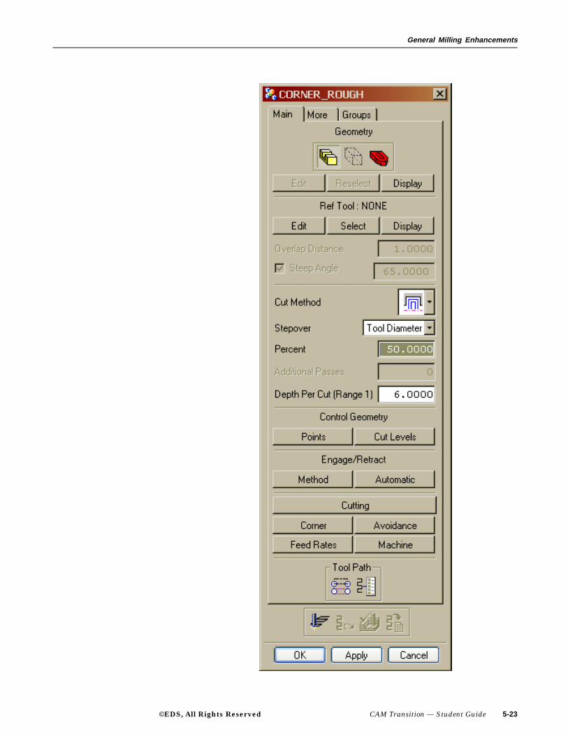
General Milling Enhancements
©EDS, All Rights Reserved CAM Transition — Student Guide 5-23

General Milling Enhancements
You will now select the reference tool that will be used tocalculate the amount of material to remove and specify theuse of the IPW.
Step 4: Selecting the Reference tool and the IPW.
You will define the width of the cut regions by referencing the toolused in the previous roughing operation.
Under Ref Tool: NONE on the CORNER_ROUGH dialog,choose the Select button and then choose the Reference toolUGT0201_021 from the Select Reference Tool dialog.
Choose OK to the Select Reference Tool dialog.
Choose the Cutting button and then choose USE 3D for the InProcess Workpiece.
Choose OK to the Cut Parameters dialog.
Choose the Generate icon.
5-24 CAM Transition — Student Guide ©EDS, All Rights Reserved
General Milling Enhancements
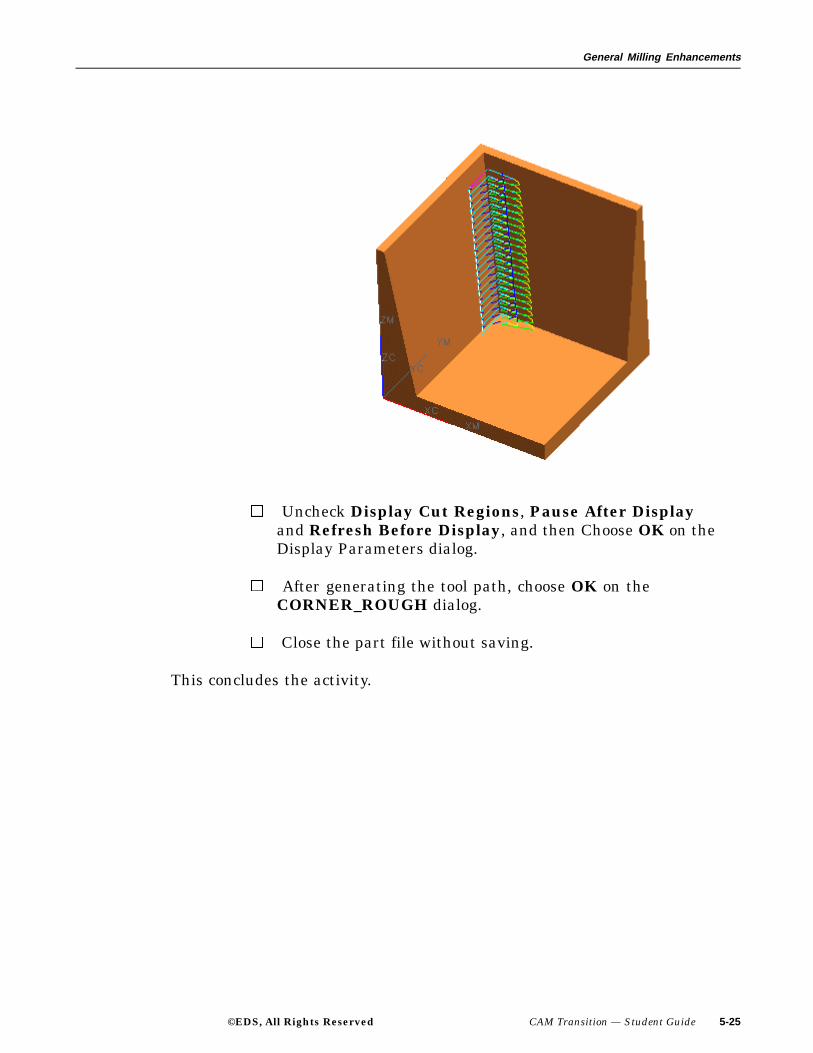
Uncheck Display Cut Regions, Pause After Displayand Refresh Before Display, and then Choose OK on theDisplay Parameters dialog.
After generating the tool path, choose OK on theCORNER_ROUGH dialog.
Close the part file without saving.
This concludes the activity.
©EDS, All Rights Reserved CAM Transition — Student Guide 5-25

General Milling Enhancements
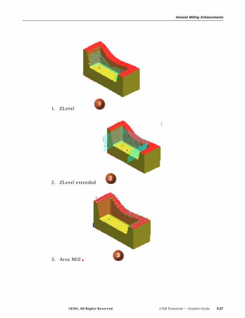
Extend at Edges
Extend at Edges allows you to specify an extension length by which thetool path will extend beyond the exterior edges of the part. The extended toolpath is a tangential extension of the faces or cut areas of the part. Thisfeature is useful when you want to machine excess material around the part.Tangential extensions are applied by turning on the Extend at Edges optionin the Cutting Parameters dialog and then specifying the extension aseither a percentage of the tool diameter or a specific distance.
Extend at Edges applies only to Flow Cut, Area Mill, and ZlevelProfile operations in Fixed Axis Surface Contouring. For ZLevel Profileoperations, you must raise the top cut level to extend cuts above the part.
5-26 CAM Transition — Student Guide ©EDS, All Rights Reserved
General Milling Enhancements
1. ZLevel
2. ZLevel extended
3. Area Mill
©EDS, All Rights Reserved CAM Transition — Student Guide 5-27
General Milling Enhancements
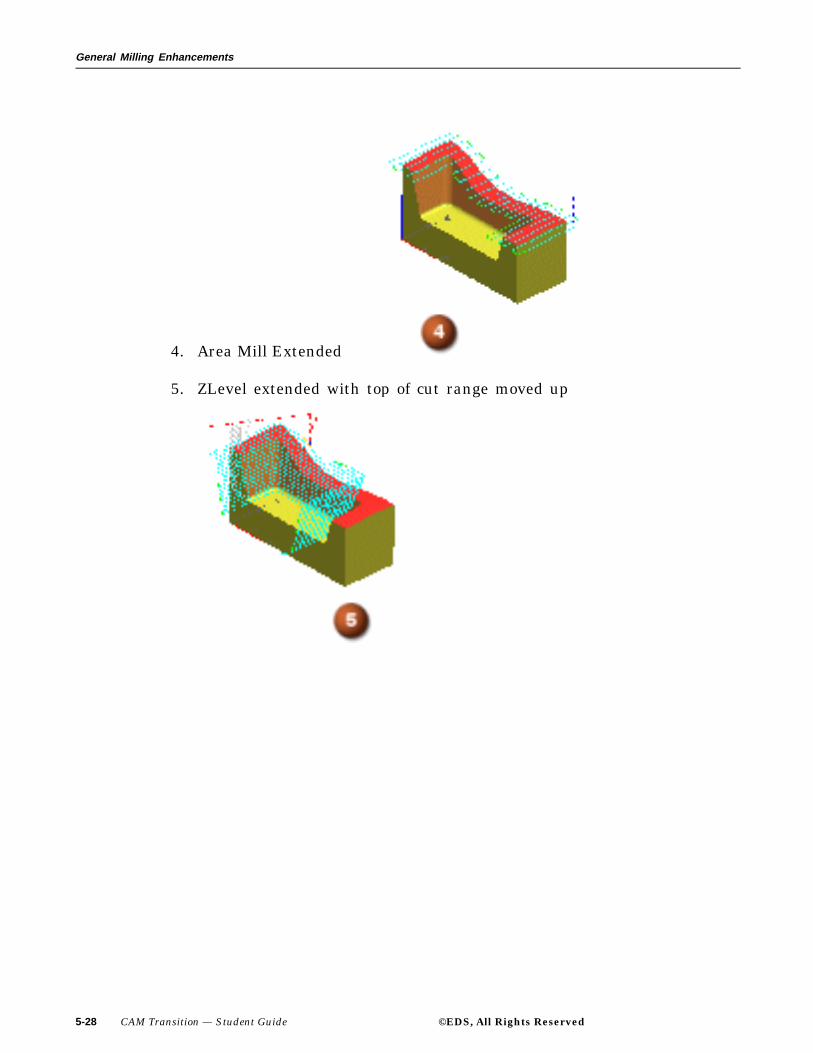
4. Area Mill Extended
5. ZLevel extended with top of cut range moved up
5-28 CAM Transition — Student Guide ©EDS, All Rights Reserved

General Milling Enhancements
Activity: Extend at Edges
In this activity you will first examine existing operations with differentcut patterns. You will then modify these operations by activating the cutparameter Extend at Edges, regenerate the operation and observe thechanges in the corresponding tool paths.
Step 1: Open the part cat_extend_edges.
If necessary, start Unigraphics NX 2.
Use File → Open.
Navigate to your parts folder and open the file.
Briefly examine the part.
Step 2: If necessary, enter the Manufacturing Application and displaythe Operation Navigator.
Choose Application → Manufacturing from the Menu bar.
Choose the Operation Navigator icon from the Resource
bar.
If necessary, change to the Program Order View of theOperation Navigator.
You will notice three operations displayed. These operationswill be replayed and then modify by applying the Extend atEdges option.
Step 3: Replay and then modify the FOLLOW_AREA operation to extendthe distance the tool overlaps the cut area.
Double-click the FOLLOW_AREA operation.
The CONTOUR_AREA dialog is displayed.
©EDS, All Rights Reserved CAM Transition — Student Guide 5-29
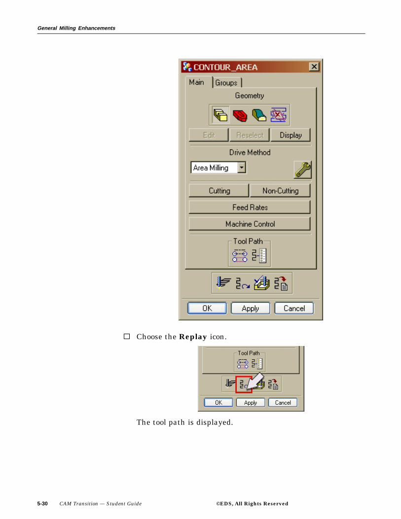
General Milling Enhancements
Choose the Replay icon.
The tool path is displayed.
5-30 CAM Transition — Student Guide ©EDS, All Rights Reserved

General Milling Enhancements
You will now modify the tool path by turning on the Extendat Edges parameter.
Select the Cutting button, then turn Extend at Edges on.
©EDS, All Rights Reserved CAM Transition — Student Guide 5-31

General Milling Enhancements
Choose OK.
Generate the tool path.
Note how the tool path extends over the surface. You will nowReplay and then modify the ZIGZAG_AREA operation toallow the tool to extend beyond the modeled areas.
Choose OK on the CONTOUR_AREA dialog.
Step 4: Replay and then modify the ZIGZAG_AREA operation to extendthe distance the tool overlaps the cut area.
Double-click the ZIGZAG_AREA operation.
The CONTOUR_AREA dialog is displayed.
5-32 CAM Transition — Student Guide ©EDS, All Rights Reserved

General Milling Enhancements
Choose the Replay icon.
The tool path is displayed.
©EDS, All Rights Reserved CAM Transition — Student Guide 5-33
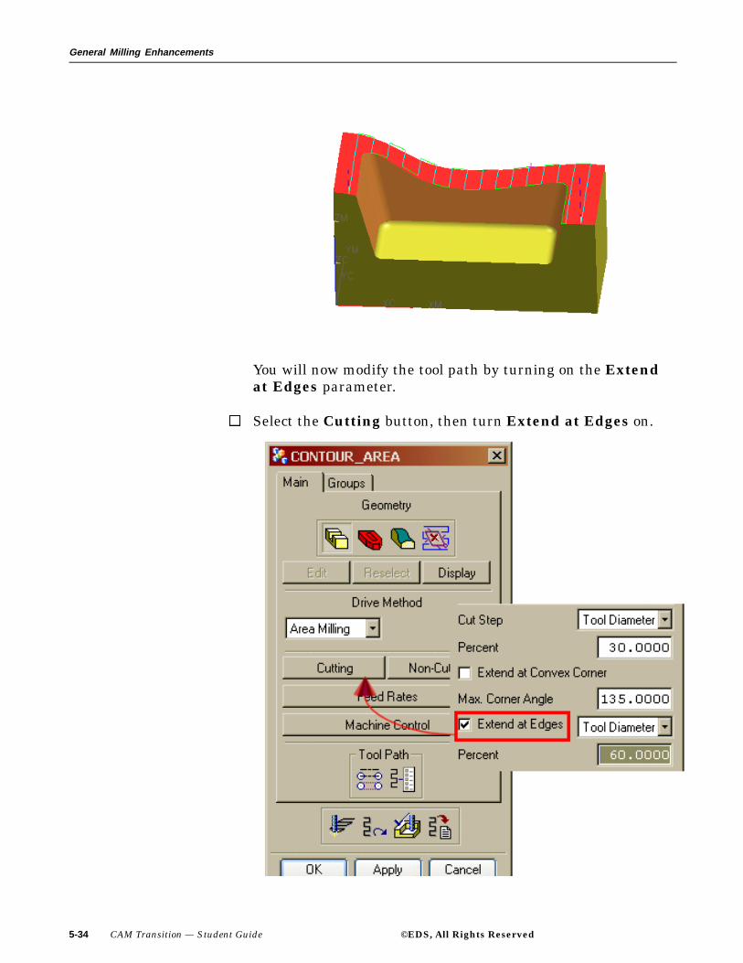
General Milling Enhancements
You will now modify the tool path by turning on the Extendat Edges parameter.
Select the Cutting button, then turn Extend at Edges on.
5-34 CAM Transition — Student Guide ©EDS, All Rights Reserved

General Milling Enhancements
Choose OK on the Cutting Parameters dialog.
Generate the tool path.
Note how the tool path extends over the surface. You will nowReplay and then modify the ZLEVEL operation to allow thetool to extend beyond the modeled areas.
Choose OK on the CONTOUR_AREA dialog.
Step 5: Replay and then modify the ZLEVEL operation to extend thedistance the tool overlaps the cut area.
Double-click the ZLEVEL operation.
The ZLEVEL_PROFILE dialog is displayed.
©EDS, All Rights Reserved CAM Transition — Student Guide 5-35

General Milling Enhancements
Choose the Replay icon.
5-36 CAM Transition — Student Guide ©EDS, All Rights Reserved

General Milling Enhancements
The tool path is displayed.
You will now modify the tool path by turning on the Extendat Edges parameter.
Select the Cutting button, then turn Extend at Edges on.
©EDS, All Rights Reserved CAM Transition — Student Guide 5-37

General Milling Enhancements
Choose OK on the Cut Parameters dialog.
Generate the tool path.
5-38 CAM Transition — Student Guide ©EDS, All Rights Reserved

General Milling Enhancements
Note how the tool path extends higher than when the Extendat Edges option is not turned on.
Choose OK on the ZLEVEL_PROFILE dialog.
Close the part file without saving the part.
This concludes the activity.
©EDS, All Rights Reserved CAM Transition — Student Guide 5-39
General Milling Enhancements
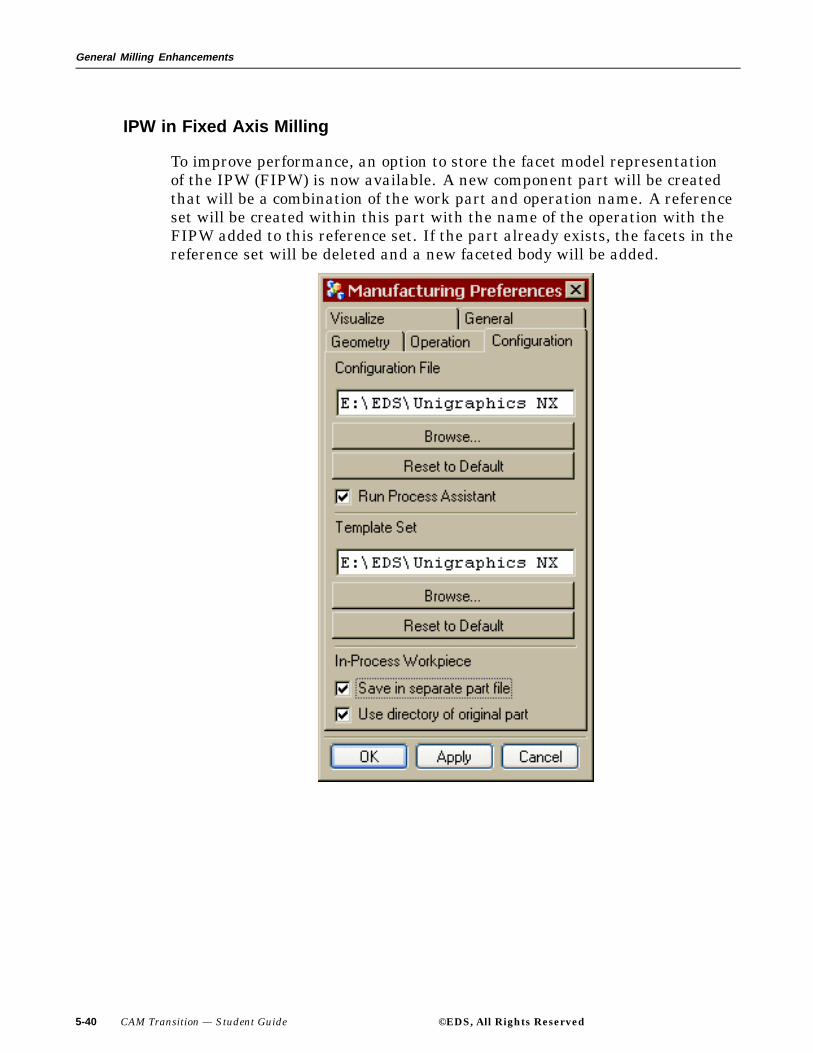
IPW in Fixed Axis Milling
To improve performance, an option to store the facet model representationof the IPW (FIPW) is now available. A new component part will be createdthat will be a combination of the work part and operation name. A referenceset will be created within this part with the name of the operation with theFIPW added to this reference set. If the part already exists, the facets in thereference set will be deleted and a new faceted body will be added.
5-40 CAM Transition — Student Guide ©EDS, All Rights Reserved
General Milling Enhancements
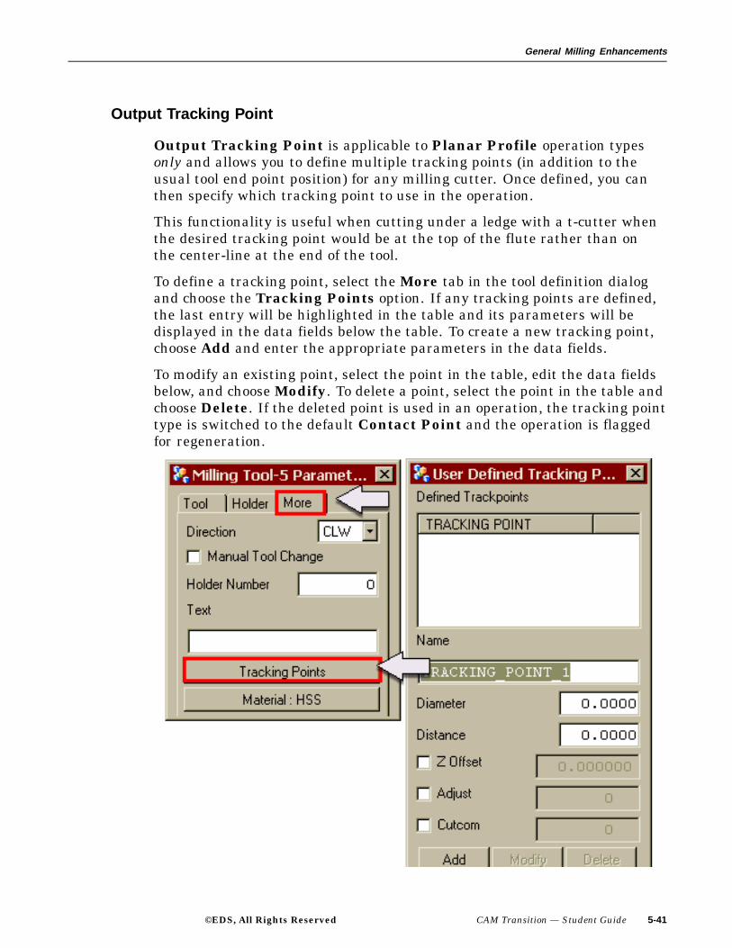
Output Tracking Point
Output Tracking Point is applicable to Planar Profile operation typesonly and allows you to define multiple tracking points (in addition to theusual tool end point position) for any milling cutter. Once defined, you canthen specify which tracking point to use in the operation.
This functionality is useful when cutting under a ledge with a t-cutter whenthe desired tracking point would be at the top of the flute rather than onthe center-line at the end of the tool.
To define a tracking point, select the More tab in the tool definition dialogand choose the Tracking Points option. If any tracking points are defined,the last entry will be highlighted in the table and its parameters will bedisplayed in the data fields below the table. To create a new tracking point,choose Add and enter the appropriate parameters in the data fields.
To modify an existing point, select the point in the table, edit the data fieldsbelow, and choose Modify. To delete a point, select the point in the table andchoose Delete. If the deleted point is used in an operation, the tracking pointtype is switched to the default Contact Point and the operation is flaggedfor regeneration.
©EDS, All Rights Reserved CAM Transition — Student Guide 5-41

General Milling Enhancements
Text Engraving
Text Engraving allows you to generate a tool path that engraves text
from drafting notes using Planar Milling or Fixed Axis Surface
Contouring operation types .
Use this operation type when engraving text (drafting notes) onto a part. Thetool will make one pass following the strokes of the font of the text objectin an "on" condition.
To use this feature you must select an existing drafting annotationor create the desired text using the Drafting Application tocreate a note. You can then select the note for cutting in eitherPlanar Milling or Surface Contouring. To create a note go to
Application Drafting → Turn off Display Drawing on the
drafting tool bar. Select the Annotation Editor . Enter thetext string that you wish to engrave in the text box. Create yourtext without a leader. Insert the text onto your part by clicking theleft mouse button on the desired area.
5-42 CAM Transition — Student Guide ©EDS, All Rights Reserved

General Milling Enhancements
To create a group of text, select the Create Geometry icon, selectmill_planar (1) as the Type (or mill_contour for contoured text),and then select the MILL_TEXT group icon (2).
Notes pertaining to text creation:
• Several fonts use multiple strokes to fill in solid areas on acharacter. If a cutter with a very small tip diameter is used forthese fonts, the areas between the strokes may not be cut.
• If you set the text depth/part stock so that the tool cuts belowthe part surface, gouge checking reports the moves as gouges.
• Check and Trim Boundaries are ignored in tool pathgeneration.
• Create text in a plane parallel to the floor plane.
• For tool path creation, the text is projected along the tool axis tothe floor plane.
• For contour text creation use ball tools. Do not use a depthgreater than the radius of the ball mill.
• In Surface Contouring, if negative floor stock ( part stock –text depth) exceeds the lower radius of the tool, a warning isgenerated when such conditions occur.
• The default tool axis is the +ZM axis.
©EDS, All Rights Reserved CAM Transition — Student Guide 5-43
General Milling Enhancements
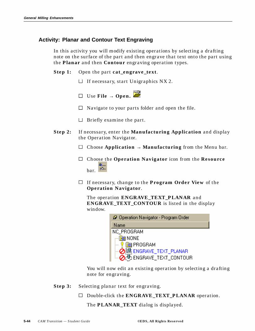
Activity: Planar and Contour Text Engraving
In this activity you will modify existing operations by selecting a draftingnote on the surface of the part and then engrave that text onto the part usingthe Planar and then Contour engraving operation types.
Step 1: Open the part cat_engrave_text.
If necessary, start Unigraphics NX 2.
Use File → Open.
Navigate to your parts folder and open the file.
Briefly examine the part.
Step 2: If necessary, enter the Manufacturing Application and displaythe Operation Navigator.
Choose Application → Manufacturing from the Menu bar.
Choose the Operation Navigator icon from the Resource
bar.
If necessary, change to the Program Order View of theOperation Navigator.
The operation ENGRAVE_TEXT_PLANAR andENGRAVE_TEXT_CONTOUR is listed in the displaywindow.
You will now edit an existing operation by selecting a draftingnote for engraving.
Step 3: Selecting planar text for engraving.
Double-click the ENGRAVE_TEXT_PLANAR operation.
The PLANAR_TEXT dialog is displayed.
5-44 CAM Transition — Student Guide ©EDS, All Rights Reserved

General Milling Enhancements
Choose the Text icon from the Main property page, choosethe Select button and then select the text string NX 2 CAMTRANSITION.
Choose OK on the Text Geometry menu.
Step 4: Set the depth of cut to .025.
Choose Text Depth from the PLANAR_TEXT dialog.
Key in the value .025.
Choose the Generate icon on the PLANAR_TEXT dialog.
©EDS, All Rights Reserved CAM Transition — Student Guide 5-45
General Milling Enhancements
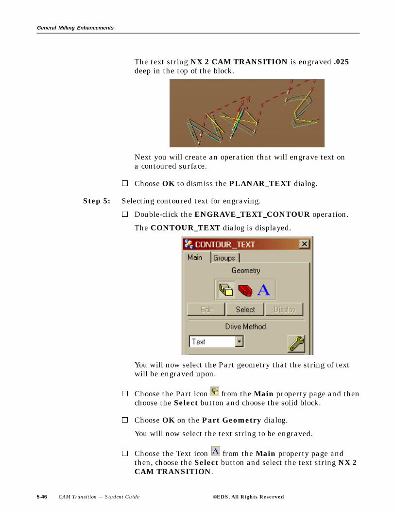
The text string NX 2 CAM TRANSITION is engraved .025deep in the top of the block.
Next you will create an operation that will engrave text ona contoured surface.
Choose OK to dismiss the PLANAR_TEXT dialog.
Step 5: Selecting contoured text for engraving.
Double-click the ENGRAVE_TEXT_CONTOUR operation.
The CONTOUR_TEXT dialog is displayed.
You will now select the Part geometry that the string of textwill be engraved upon.
Choose the Part icon from the Main property page and thenchoose the Select button and choose the solid block.
Choose OK on the Part Geometry dialog.
You will now select the text string to be engraved.
Choose the Text icon from the Main property page andthen, choose the Select button and select the text string NX 2CAM TRANSITION.
5-46 CAM Transition — Student Guide ©EDS, All Rights Reserved

General Milling Enhancements
Choose OK on the Text Geometry menu.
Step 6: Set the depth of cut for engraving to .020.
Choose the Cutting button.
The Cutting Parameters dialog is displayed.
Key in the value 0 for Part Stock and then key in the value of.020 for Text Depth.
Choose OK on the Cutting Parameters dialog.
Choose the Generate icon on the CONTOUR_TEXT dialog.
The text string NX 2 CAM TRANSITION is engraved .020deep on the top of the block.
Choose OK on the CONTOUR_TEXT dialog.
Close the Part file without saving the part.
This concludes the activity.
©EDS, All Rights Reserved CAM Transition — Student Guide 5-47
General Milling Enhancements
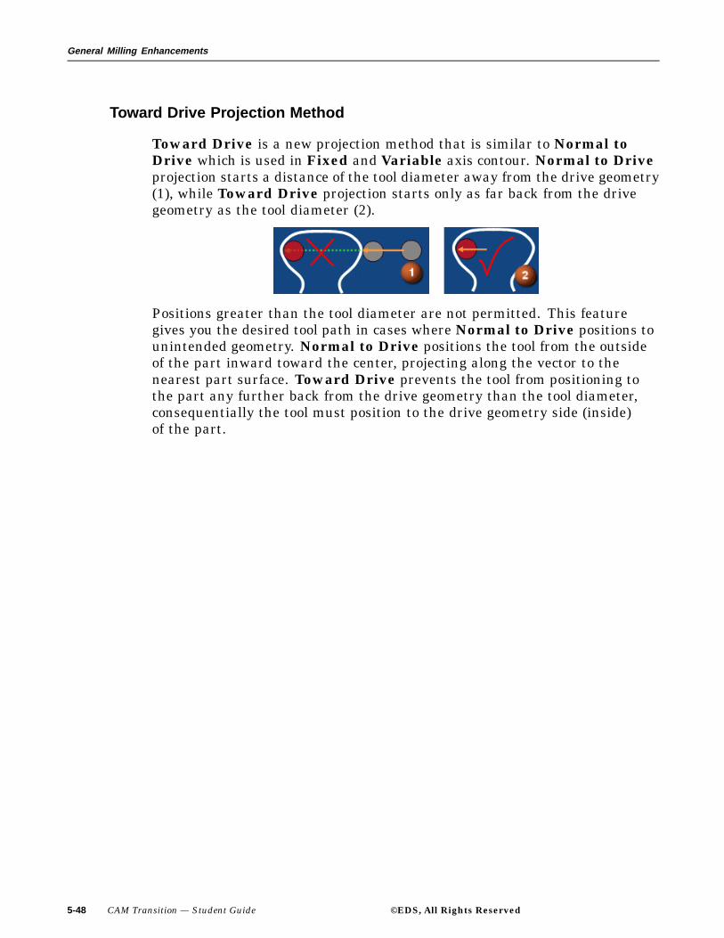
Toward Drive Projection Method
Toward Drive is a new projection method that is similar to Normal toDrive which is used in Fixed and Variable axis contour. Normal to Driveprojection starts a distance of the tool diameter away from the drive geometry(1), while Toward Drive projection starts only as far back from the drivegeometry as the tool diameter (2).
Positions greater than the tool diameter are not permitted. This featuregives you the desired tool path in cases where Normal to Drive positions tounintended geometry. Normal to Drive positions the tool from the outsideof the part inward toward the center, projecting along the vector to thenearest part surface. Toward Drive prevents the tool from positioning tothe part any further back from the drive geometry than the tool diameter,consequentially the tool must position to the drive geometry side (inside)of the part.
5-48 CAM Transition — Student Guide ©EDS, All Rights Reserved

General Milling Enhancements
Trochoidal Cut Pattern
The Trochoidal Cut pattern feature is used when you need to limit excessivestep over to prevent tool breakage when the tool is fully embedded into a cutand when you want to avoid cutting excess material. Most cut patternsgenerate embedded regions between islands and parts during the engage aswell as in narrow areas. The use of Trochoidal Cut pattern eliminates thisproblem by creating a trochoidal cut offset from the part. The tool path cutsalong the part, and then uses a smooth follow pattern to cut the regionsinward. Trochoidal cutting can be described as a method of milling where thecutter moves in a circular looping pattern while the center of the circle movesalong a path. This is similar in appearance to a stretched-out spring.
1. Stepover
2. Path Width
The following figure illustrates the Trochoidal cut pattern. Note the loopingcut pattern. The cutter machines the material in small looping motions,spinning as it moves in a looping cut pattern. Compare this with theconventional method of cutting where the cutter moves forward in a straightpath and is surrounded by material on all sides.
©EDS, All Rights Reserved CAM Transition — Student Guide 5-49

General Milling Enhancements
This cut pattern is useful in high speed milling applications since itavoids embedding the tool in material and limits the amount of step over.Trochoidal Cut method is currently available in Planar, Cavity, andFace Milling.
5-50 CAM Transition — Student Guide ©EDS, All Rights Reserved
General Milling Enhancements
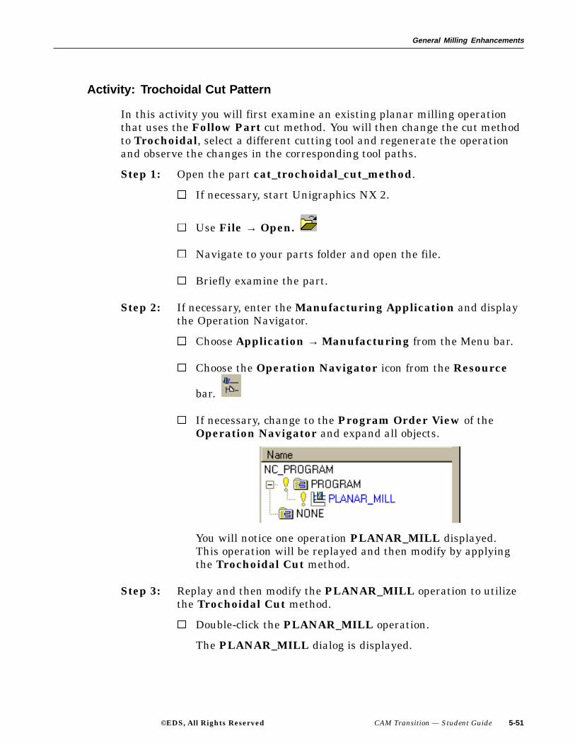
Activity: Trochoidal Cut Pattern
In this activity you will first examine an existing planar milling operationthat uses the Follow Part cut method. You will then change the cut methodto Trochoidal, select a different cutting tool and regenerate the operationand observe the changes in the corresponding tool paths.
Step 1: Open the part cat_trochoidal_cut_method.
If necessary, start Unigraphics NX 2.
Use File → Open.
Navigate to your parts folder and open the file.
Briefly examine the part.
Step 2: If necessary, enter the Manufacturing Application and displaythe Operation Navigator.
Choose Application → Manufacturing from the Menu bar.
Choose the Operation Navigator icon from the Resource
bar.
If necessary, change to the Program Order View of theOperation Navigator and expand all objects.
You will notice one operation PLANAR_MILL displayed.This operation will be replayed and then modify by applyingthe Trochoidal Cut method.
Step 3: Replay and then modify the PLANAR_MILL operation to utilizethe Trochoidal Cut method.
Double-click the PLANAR_MILL operation.
The PLANAR_MILL dialog is displayed.
©EDS, All Rights Reserved CAM Transition — Student Guide 5-51

General Milling Enhancements
Choose the Replay icon.
5-52 CAM Transition — Student Guide ©EDS, All Rights Reserved
General Milling Enhancements
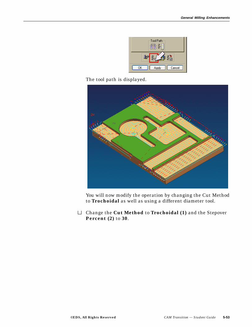
The tool path is displayed.
You will now modify the operation by changing the Cut Methodto Trochoidal as well as using a different diameter tool.
Change the Cut Method to Trochoidal (1) and the StepoverPercent (2) to 30.
©EDS, All Rights Reserved CAM Transition — Student Guide 5-53

General Milling Enhancements
Under the Groups tab, change the tool from UGTI0201_012to UGTI0201_011.
Choose OK on the Reselect Tool dialog.
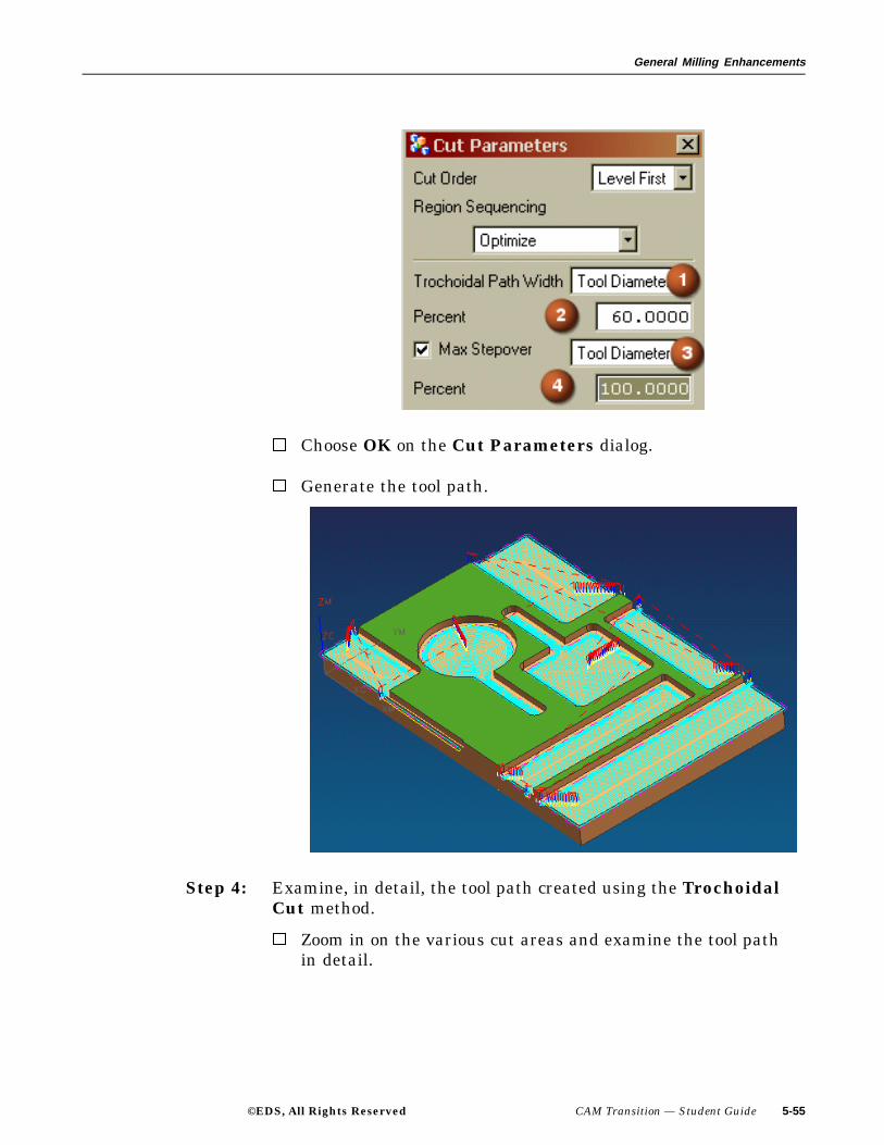
Under the Main tab, select the Cutting button and from theCut Parameters dialog, if necessary, change the TrochoidalPath Width (1) to Tool Diameter, Percent (2) to 60, MaxStepover (3) to Tool Diameter and Percent (4) to 100.
5-54 CAM Transition — Student Guide ©EDS, All Rights Reserved
General Milling Enhancements
Choose OK on the Cut Parameters dialog.
Generate the tool path.
Step 4: Examine, in detail, the tool path created using the TrochoidalCut method.
Zoom in on the various cut areas and examine the tool pathin detail.
©EDS, All Rights Reserved CAM Transition — Student Guide 5-55

General Milling Enhancements
Close, without saving, the Part file.
This concludes the activity.
5-56 CAM Transition — Student Guide ©EDS, All Rights Reserved
General Milling Enhancements
Zlevel Corner Finishing with Reference Tool
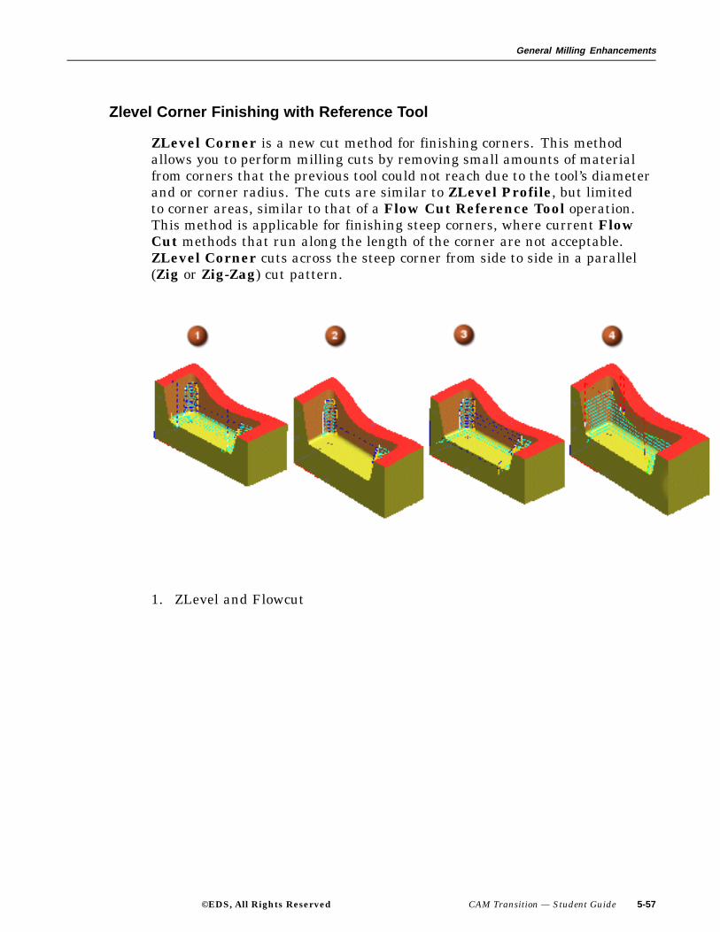
ZLevel Corner is a new cut method for finishing corners. This methodallows you to perform milling cuts by removing small amounts of materialfrom corners that the previous tool could not reach due to the tool’s diameterand or corner radius. The cuts are similar to ZLevel Profile, but limitedto corner areas, similar to that of a Flow Cut Reference Tool operation.This method is applicable for finishing steep corners, where current FlowCut methods that run along the length of the corner are not acceptable.ZLevel Corner cuts across the steep corner from side to side in a parallel(Zig or Zig-Zag) cut pattern.
1. ZLevel and Flowcut
©EDS, All Rights Reserved CAM Transition — Student Guide 5-57

General Milling Enhancements
2. ZLevel Steep with Reference Tool
3. ZLevel with Reference Tool
5-58 CAM Transition — Student Guide ©EDS, All Rights Reserved

General Milling Enhancements
4. Z-Level
©EDS, All Rights Reserved CAM Transition — Student Guide 5-59

General Milling Enhancements
ZigZag 3D Stepover
In Area Milling Drive Method of Fixed Axis Surface Contouring, youcan now use the On Part option to maintain a specified step over distanceon steep and non-steep surfaces for all parallel cut patterns (Zig, Zig-Zag,Zig with Lifts, Zig with Contour, Zig with Stepover). Previously, youcould only use On Part for the Follow Periphery cut pattern. On Partcalculates the tool path directly on the part surface instead of calculating iton a plane normal to the tool axis and then projecting onto the part surface asdoes the On Plane option.
On Part ensures that the step over distance between successive cuttingpasses is consistent regardless of the steepness of the surface. The specifiedstep over is the maximum step over allowed across the part, but it can vary toa lesser value based on the steepness of the surface.
5-60 CAM Transition — Student Guide ©EDS, All Rights Reserved

General Milling Enhancements
2D Contact Contour
When using 2D Contact Contour, the tool path starts at the center line,moves to contact points, and then moves back to the center line. The traversalmoves at the beginning of the tool path are at the tool center line. For theengage move, cutter compensation is automatically turned on, and the toolpath starts at the tool center line and ends at the contact point. The pathstays at the contact points until the tool reaches the retract move when cuttercompensation is automatically turned off. This move starts at the contactpoint and ends at the center line point. Further moves to retract and traversethe tool are output at the center line. The 2D Contact Contour functionalityis available only in the operation type, Planar Profile.
The advantages of using 2D Contact Contour functionality are as follows:
• Compensate for tool wear without having to regenerate the tool pathsince the output data is based on the relationship of the cutter to thegeometry shape.
• Wide variation in tool size usage by using cutter compensation at themachine tool.
• Output data in the tool path can reflect the actual part dimensions of thepart so that you can compare the tool path data in the program withpart geometry dimensions.
The following is an example of a tool path without using 2D ContactContour operation type:
©EDS, All Rights Reserved CAM Transition — Student Guide 5-61
General Milling Enhancements
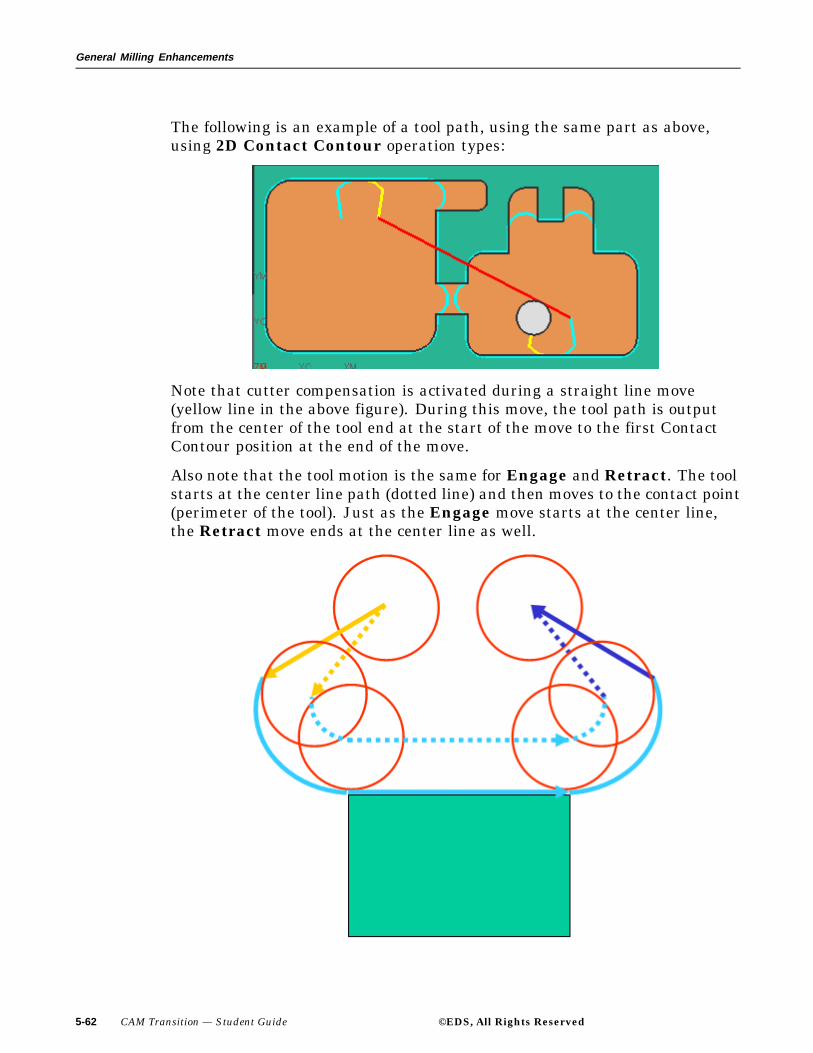
The following is an example of a tool path, using the same part as above,using 2D Contact Contour operation types:
Note that cutter compensation is activated during a straight line move(yellow line in the above figure). During this move, the tool path is outputfrom the center of the tool end at the start of the move to the first ContactContour position at the end of the move.
Also note that the tool motion is the same for Engage and Retract. The toolstarts at the center line path (dotted line) and then moves to the contact point(perimeter of the tool). Just as the Engage move starts at the center line,the Retract move ends at the center line as well.
5-62 CAM Transition — Student Guide ©EDS, All Rights Reserved
General Milling Enhancements
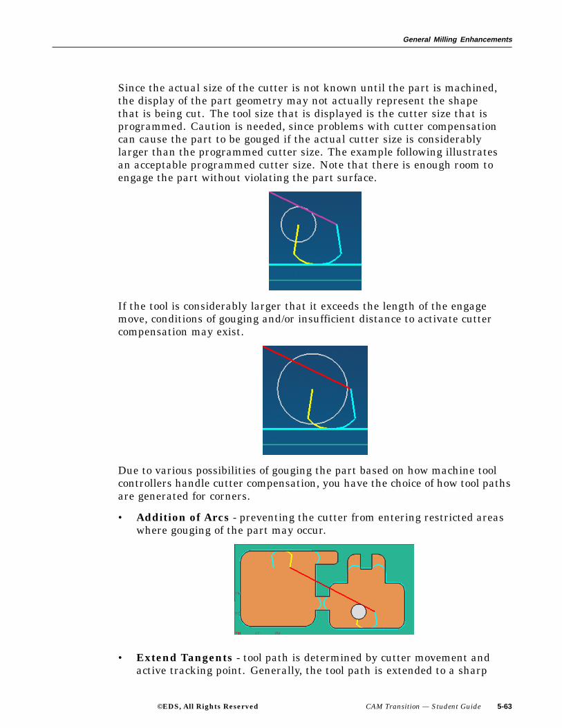
Since the actual size of the cutter is not known until the part is machined,the display of the part geometry may not actually represent the shapethat is being cut. The tool size that is displayed is the cutter size that isprogrammed. Caution is needed, since problems with cutter compensationcan cause the part to be gouged if the actual cutter size is considerablylarger than the programmed cutter size. The example following illustratesan acceptable programmed cutter size. Note that there is enough room toengage the part without violating the part surface.
If the tool is considerably larger that it exceeds the length of the engagemove, conditions of gouging and/or insufficient distance to activate cuttercompensation may exist.
Due to various possibilities of gouging the part based on how machine toolcontrollers handle cutter compensation, you have the choice of how tool pathsare generated for corners.
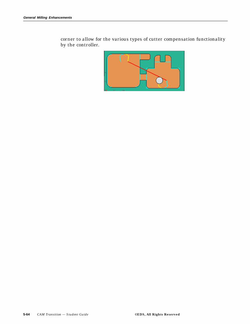
• Addition of Arcs - preventing the cutter from entering restricted areaswhere gouging of the part may occur.
• Extend Tangents - tool path is determined by cutter movement andactive tracking point. Generally, the tool path is extended to a sharp
©EDS, All Rights Reserved CAM Transition — Student Guide 5-63
General Milling Enhancements
corner to allow for the various types of cutter compensation functionalityby the controller.
5-64 CAM Transition — Student Guide ©EDS, All Rights Reserved
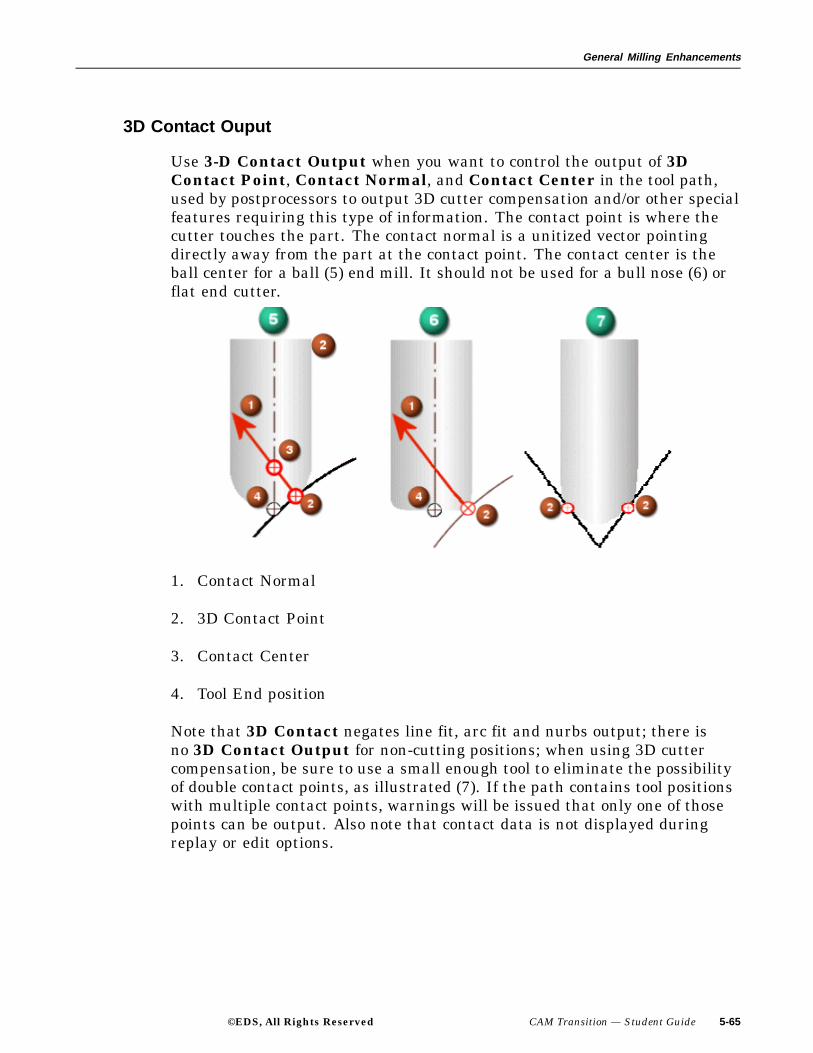
General Milling Enhancements
3D Contact Ouput
Use 3-D Contact Output when you want to control the output of 3DContact Point, Contact Normal, and Contact Center in the tool path,used by postprocessors to output 3D cutter compensation and/or other specialfeatures requiring this type of information. The contact point is where thecutter touches the part. The contact normal is a unitized vector pointingdirectly away from the part at the contact point. The contact center is theball center for a ball (5) end mill. It should not be used for a bull nose (6) orflat end cutter.
1. Contact Normal
2. 3D Contact Point
3. Contact Center
4. Tool End position
Note that 3D Contact negates line fit, arc fit and nurbs output; there isno 3D Contact Output for non-cutting positions; when using 3D cuttercompensation, be sure to use a small enough tool to eliminate the possibilityof double contact points, as illustrated (7). If the path contains tool positionswith multiple contact points, warnings will be issued that only one of thosepoints can be output. Also note that contact data is not displayed duringreplay or edit options.
©EDS, All Rights Reserved CAM Transition — Student Guide 5-65

General Milling Enhancements
Summary
In this lesson, you were introduced to the new robust General Millingenhancements found in NX 2 that will accelerate your ability to use advancedcutting and machine tool technologies. These enhancements are:
• Automatic wall detection in Face Milling
• Cut area in Face Milling operations
• Preselect wall geometry in Face Milling
• Wall stock and wall geometry in Face Milling
• Corner roughing
• Extend at edges
• IPW in Fixed Axis milling
• ?Output tracking point
• Text engraving
• Toward drive projection method
• Trochoidal cut pattern
• Zlevel Corner finishing with reference tool
• ZigZag 3D stepover
• 2D Contact Contour
• 3D Contact Output
5-66 CAM Transition — Student Guide ©EDS, All Rights Reserved

Lesson
6 Turning Enhancements
Purpose
The modern lathe has numerous options that allow you to turn and millvarious part configurations in one setup. The functionality of A and B-Axiscontrol, further enhances your ability to machine the most complex partson mill-turn centers.
Objectives
Upon completion of this lesson, you will be able to use:
• A-Axis Tool control
• B-Axis Tool control
©EDS, All Rights Reserved CAM Transition — Student Guide 6-1
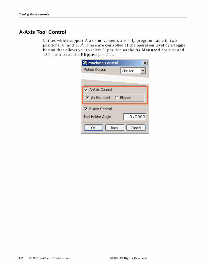
Turning Enhancements
A-Axis Tool Control
Lathes which support A-axis movements are only programmable in twopositions. 0 and 180 . These are controlled at the operation level by a togglebutton that allows you to select 0 position as the As Mounted position and180 position as the Flipped position.
6-2 CAM Transition — Student Guide ©EDS, All Rights Reserved
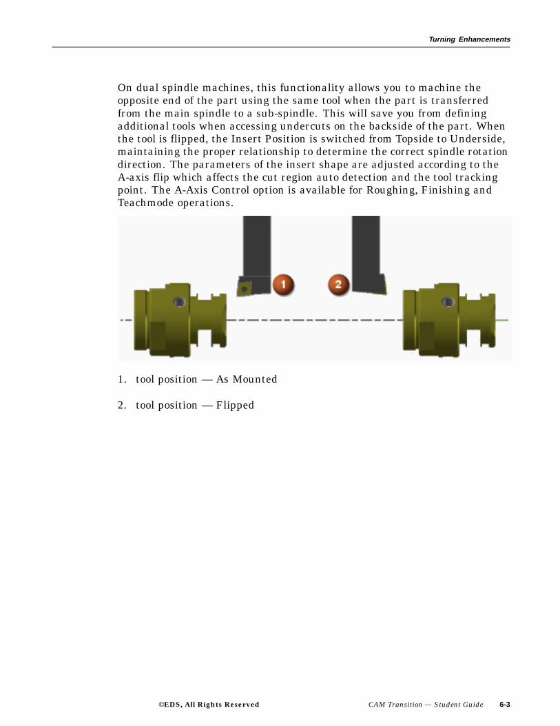
Turning Enhancements
On dual spindle machines, this functionality allows you to machine theopposite end of the part using the same tool when the part is transferredfrom the main spindle to a sub-spindle. This will save you from definingadditional tools when accessing undercuts on the backside of the part. Whenthe tool is flipped, the Insert Position is switched from Topside to Underside,maintaining the proper relationship to determine the correct spindle rotationdirection. The parameters of the insert shape are adjusted according to theA-axis flip which affects the cut region auto detection and the tool trackingpoint. The A-Axis Control option is available for Roughing, Finishing andTeachmode operations.
1. tool position — As Mounted
2. tool position — Flipped
©EDS, All Rights Reserved CAM Transition — Student Guide 6-3
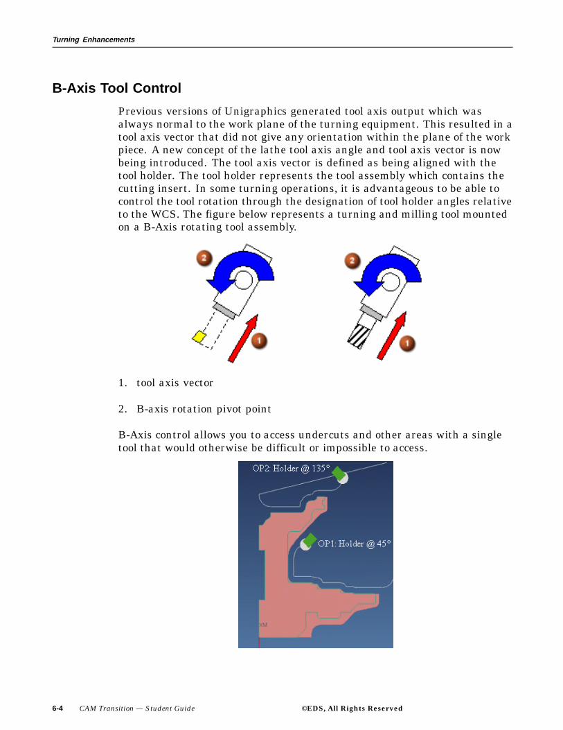
Turning Enhancements
B-Axis Tool Control
Previous versions of Unigraphics generated tool axis output which wasalways normal to the work plane of the turning equipment. This resulted in atool axis vector that did not give any orientation within the plane of the workpiece. A new concept of the lathe tool axis angle and tool axis vector is nowbeing introduced. The tool axis vector is defined as being aligned with thetool holder. The tool holder represents the tool assembly which contains thecutting insert. In some turning operations, it is advantageous to be able tocontrol the tool rotation through the designation of tool holder angles relativeto the WCS. The figure below represents a turning and milling tool mountedon a B-Axis rotating tool assembly.
1. tool axis vector
2. B-axis rotation pivot point
B-Axis control allows you to access undercuts and other areas with a singletool that would otherwise be difficult or impossible to access.
6-4 CAM Transition — Student Guide ©EDS, All Rights Reserved

Turning Enhancements
Summary
The complexity of today’s modern mill-turn centers allows you to machinethe most complex parts in one setup. These complex parts can be machinedthrough rotational A and B axis movements of the spindle. In this lesson,you learned the use of:
• A-Axis Tool control options
• B-Axis Tool control options
©EDS, All Rights Reserved CAM Transition — Student Guide 6-5


Lesson
7 Hole Making Enhancements
Purpose
To gain an overview in the application and use of new features andfunctionality found in the Hole Making module.
Objectives
In this lesson, you will learn about features and functionality pertaining to:
• Alternate Groups of Operations
• Cut Area
• Feature Recognition
• Feature Status
• Holder Types
• 3D In Process Work Piece (IPW)
• Maximum Cut Depth and Extended Length
• Multiple Selection
• Inch and Metric Availability Within Tool Query
©EDS, All Rights Reserved CAM Transition — Student Guide 7-1
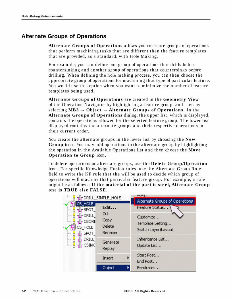
Hole Making Enhancements
Alternate Groups of Operations
Alternate Groups of Operations allows you to create groups of operationsthat perform machining tasks that are different than the feature templatesthat are provided, as a standard, with Hole Making.
For example, you can define one group of operations that drills beforecountersinking and another group of operations that countersinks beforedrilling. When defining the hole making process, you can then choose theappropriate group of operations for machining that type of particular feature.You would use this option when you want to minimize the number of featuretemplates being used.
Alternate Groups of Operations are created in the Geometry Viewof the Operation Navigator by highlighting a feature group, and then byselecting MB3 → Object → Alternate Groups of Operations. In theAlternate Groups of Operations dialog, the upper list, which is displayed,contains the operations allowed for the selected feature group. The lower listdisplayed contains the alternate groups and their respective operations intheir current order.
You create the alternate groups in the lower list by choosing the NewGroup icon. You may add operations to the alternate group by highlightingthe operation in the Available Operations list and then choose the MoveOperation to Group icon.
To delete operations or alternate groups, use the Delete Group/Operationicon. For specific Knowledge Fusion rules, use the Alternate Group Rulefield to write the KF rule that the will be used to decide which group ofoperations will machine that particular feature group. For example, a rulemight be as follows: If the material of the part is steel, Alternate Groupone is TRUE else FALSE.
7-2 CAM Transition — Student Guide ©EDS, All Rights Reserved

Hole Making Enhancements
Cut Area
Cut Area allows you to reduce the scope of machinable feature identificationsby creating a MILL_AREA group that identifies specific faces to bemachined. When there is no Cut Area geometry identified, the featureidentification will be the entire part. The WORKPIECE group should bespecified as the parent when creating this MILL_AREA group.
The face geometry defining the Cut Area is specified within theMILL_AREA group. Selected points and arcs will be identified during thefeature grouping regardless of Part or Cut Area geometry since Cut Areageometry is based on faces and Part geometry is based on bodies. Points andarcs are considered neither faces or bodies.
©EDS, All Rights Reserved CAM Transition — Student Guide 7-3
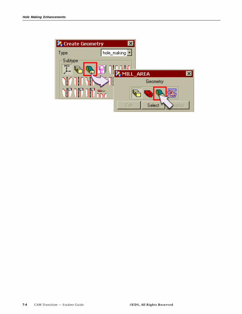
Hole Making Enhancements
7-4 CAM Transition — Student Guide ©EDS, All Rights Reserved

Hole Making Enhancements
Feature Recognition
Hole Making will recognize simple, counterbored, and countersunk holefeatures that have not been explicitly created as a Unigraphics feature.These features are based on cylinders with diameter and depth parameters,cones with maximum and minimum cone diameters as well as cone angleand planes.
A simple hole is created from a cylinder with planes designating the topand bottom of the hole.
1. Cylinder
2. Cylinder and Plane
3. Cylinder and Cone
4. Cylinder, Cone, Plane
5. Cylinder, Cone, Plane
A counterbored hole consists of a cylinder and plane, which designate thecounterbore, with the addition of a simple hole feature.
1. Cylinder, plane, simple hole
2. Cylinder, plane, simple hole
3. Cylinder, plane, cone, simple hole
©EDS, All Rights Reserved CAM Transition — Student Guide 7-5

Hole Making Enhancements
4. Cylinder, plane, cone, simple hole
5. Cylinder, plane, cone, simple hole
A countersink hole consists of a cone with the addition of a simple hole.
1. Cone, plane, simple hole
2. Cone, plane, simple hole
3. Cone, plane, simple hole
4. Cone, plane, simple hole
5. Cone, plane, simple hole
To apply this functionality, declare all simple hole, counterbored hole andcountersunk hole shapes as machinable features and then create theoperation and generate the subsequent tool path.
7-6 CAM Transition — Student Guide ©EDS, All Rights Reserved

Hole Making Enhancements
Activity: Feature Recognition
In this activity you will utilize the Hole Making processor to machine simple,counter bored and countersunk hole shapes that have not been createdexplicitly as features. You will first replay existing operations, that machinesonly the holes that have been modelled as features. You will then use theFeature Recognition option to recognize holes that were created by themethod of subtracting cylinders from the solid body. Finally, you will createoperations that will machine all of the holes in the part.
Step 1: Open the part cat_hole_making_feature.
If necessary, start Unigraphics NX 2.
Use File → Open.
Navigate to your parts folder and open the file.
Briefly examine the part.
Step 2: If necessary, enter the Manufacturing Application and displaythe Operation Navigator.
Choose Application → Manufacturing from the Menu bar.
Choose the Operation Navigator icon from the Resource
bar.
If necessary, change to the Program Order View of theOperation Navigatorand expand the SPOT_DRILL,DRILL and COUNTERBORE objects.
©EDS, All Rights Reserved CAM Transition — Student Guide 7-7
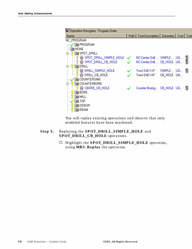
Hole Making Enhancements
You will replay existing operations and observe that onlymodeled features have been machined.
Step 3: Replaying the SPOT_DRILL_SIMPLE_HOLE andSPOT_DRILL_CB_HOLE operations.
Highlight the SPOT_DRILL_SIMPLE_HOLE operation,using MB3, Replay the operation.
7-8 CAM Transition — Student Guide ©EDS, All Rights Reserved
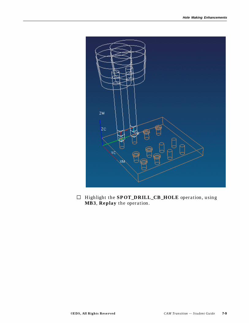
Hole Making Enhancements
Highlight the SPOT_DRILL_CB_HOLE operation, usingMB3, Replay the operation.
©EDS, All Rights Reserved CAM Transition — Student Guide 7-9
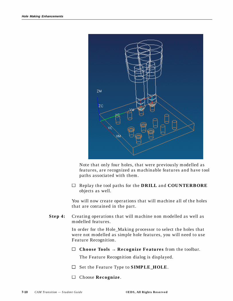
Hole Making Enhancements
Note that only four holes, that were previously modelled asfeatures, are recognized as machinable features and have toolpaths associated with them.
Replay the tool paths for the DRILL and COUNTERBOREobjects as well.
You will now create operations that will machine all of the holesthat are contained in the part.
Step 4: Creating operations that will machine non modelled as well asmodelled features.
In order for the Hole_Making processor to select the holes thatwere not modelled as simple hole features, you will need to useFeature Recognition.
Choose Tools → Recognize Features from the toolbar.
The Feature Recognition dialog is displayed.
Set the Feature Type to SIMPLE_HOLE.
Choose Recognize.
7-10 CAM Transition — Student Guide ©EDS, All Rights Reserved
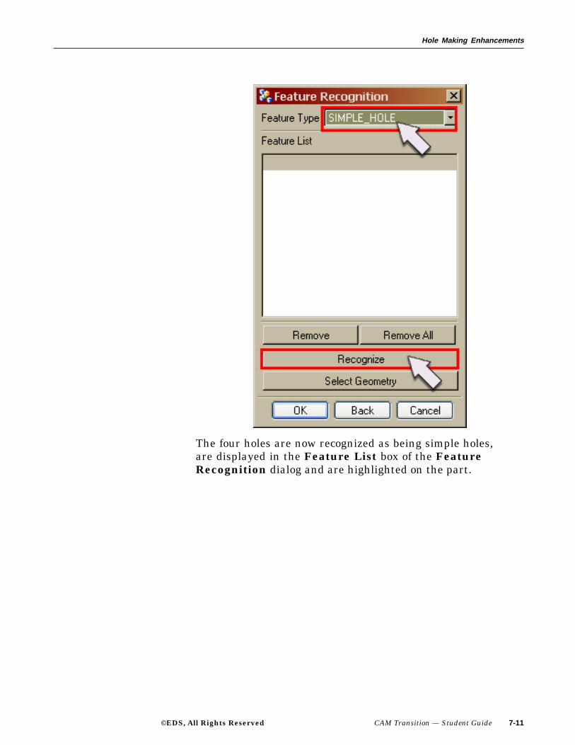
Hole Making Enhancements
The four holes are now recognized as being simple holes,are displayed in the Feature List box of the FeatureRecognition dialog and are highlighted on the part.
©EDS, All Rights Reserved CAM Transition — Student Guide 7-11

Hole Making Enhancements
You will now use the Feature Recognition function to recognizethe counterbored hole feature types as machinable features.
7-12 CAM Transition — Student Guide ©EDS, All Rights Reserved
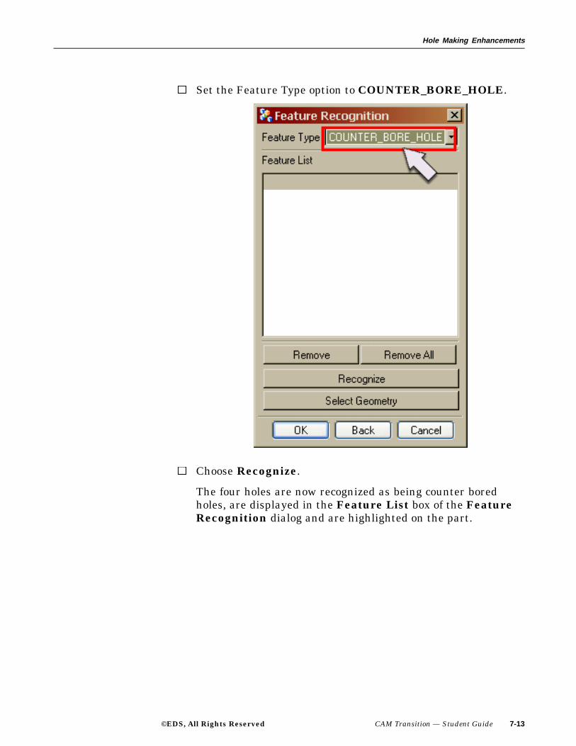
Hole Making Enhancements
Set the Feature Type option to COUNTER_BORE_HOLE.
Choose Recognize.
The four holes are now recognized as being counter boredholes, are displayed in the Feature List box of the FeatureRecognition dialog and are highlighted on the part.
©EDS, All Rights Reserved CAM Transition — Student Guide 7-13

Hole Making Enhancements
Choose OK on the Feature Recognition dialog.
You will now create the operations that will machine all holesthat are contained in the part.
Choose the Create Geometry icon on the toolbar.
If necessary, set the Type to hole_making and the ParentGroup to WORKPIECE.
7-14 CAM Transition — Student Guide ©EDS, All Rights Reserved

Hole Making Enhancements
Choose the SIMPLE_HOLE icon from theCreate Geometrydialog.
Choose OK from the Create Geometry dialog to begingenerating the operations.
The Information Window and SIMPLE_HOLE dialog isdisplayed.
©EDS, All Rights Reserved CAM Transition — Student Guide 7-15

Hole Making Enhancements
Dismiss the Information window and choose OK on theSIMPLE_HOLE dialog. The diameter of the hole will beused as the classification criteria. You will now create theoperations for the counter bored holes.
Choose the Create Geometry icon from the tool bar.
The Create Geometry dialog is displayed.
Choose the CB_HOLE icon.
7-16 CAM Transition — Student Guide ©EDS, All Rights Reserved

Hole Making Enhancements
Choose OK from the Create Geometry dialog to begingenerating the operations.
The Information Window and CB_HOLE dialog is displayed.
©EDS, All Rights Reserved CAM Transition — Student Guide 7-17
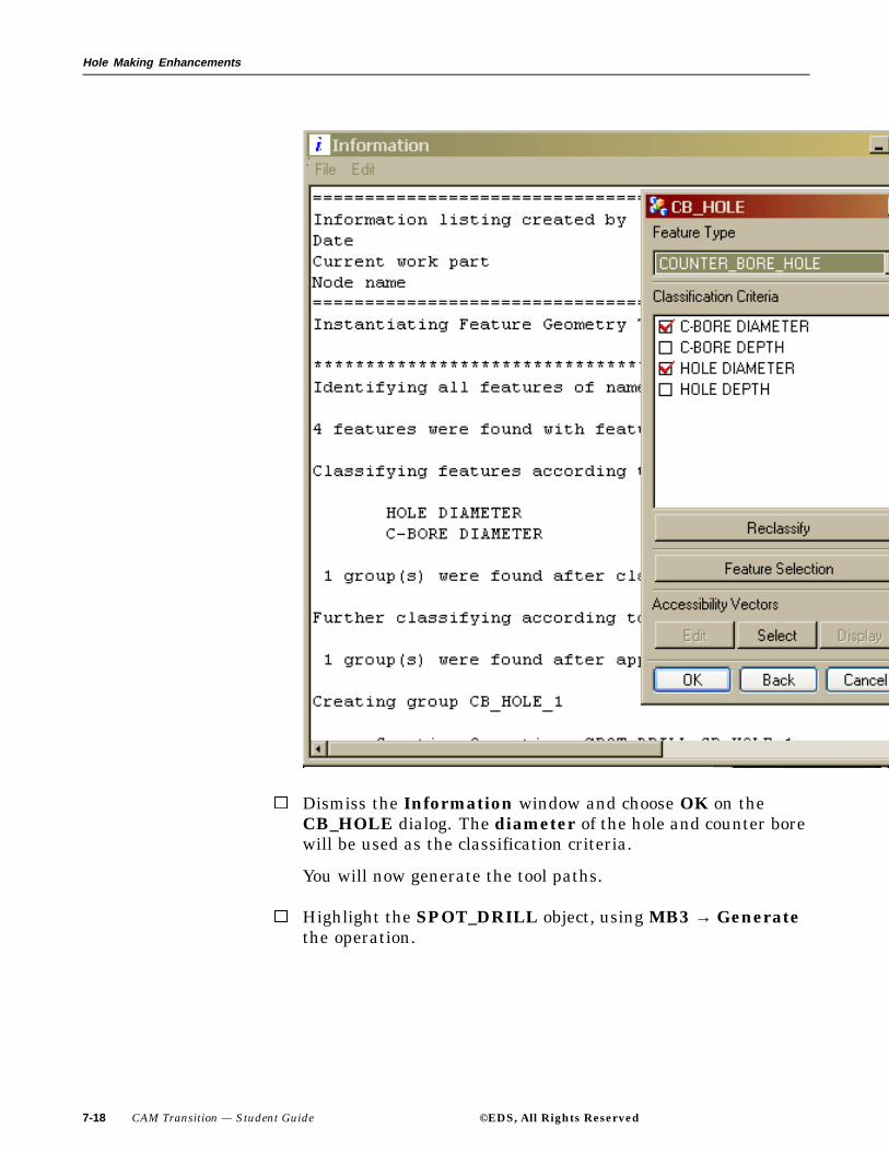
Hole Making Enhancements
Dismiss the Information window and choose OK on theCB_HOLE dialog. The diameter of the hole and counter borewill be used as the classification criteria.
You will now generate the tool paths.
Highlight the SPOT_DRILL object, using MB3 → Generatethe operation.
7-18 CAM Transition — Student Guide ©EDS, All Rights Reserved
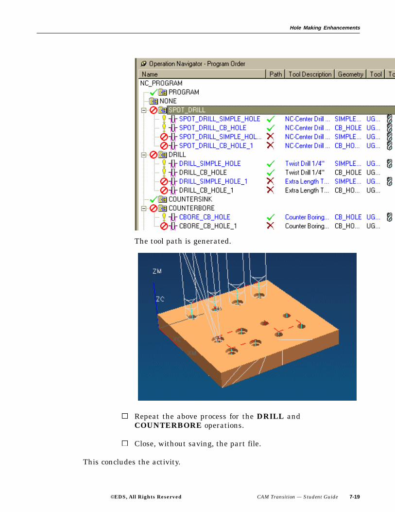
Hole Making Enhancements
The tool path is generated.
Repeat the above process for the DRILL andCOUNTERBORE operations.
Close, without saving, the part file.
This concludes the activity.
©EDS, All Rights Reserved CAM Transition — Student Guide 7-19

Hole Making Enhancements
Feature Status
The Feature Status option allows you to identify features that have not beenmachined. This can occur due to collisions with clamps or the tool holder. Tocheck the feature status, choose the feature group icon in the OperationNavigator and use MB3 → Object Feature Status.
7-20 CAM Transition — Student Guide ©EDS, All Rights Reserved

Hole Making Enhancements
Holder Types
Holder Type is found in the Tap tool dialog that allows you to specify eithera rigid or float tap type holder. For legacy operations, Holder Type needs tobe customized into the Tap dialog.
©EDS, All Rights Reserved CAM Transition — Student Guide 7-21
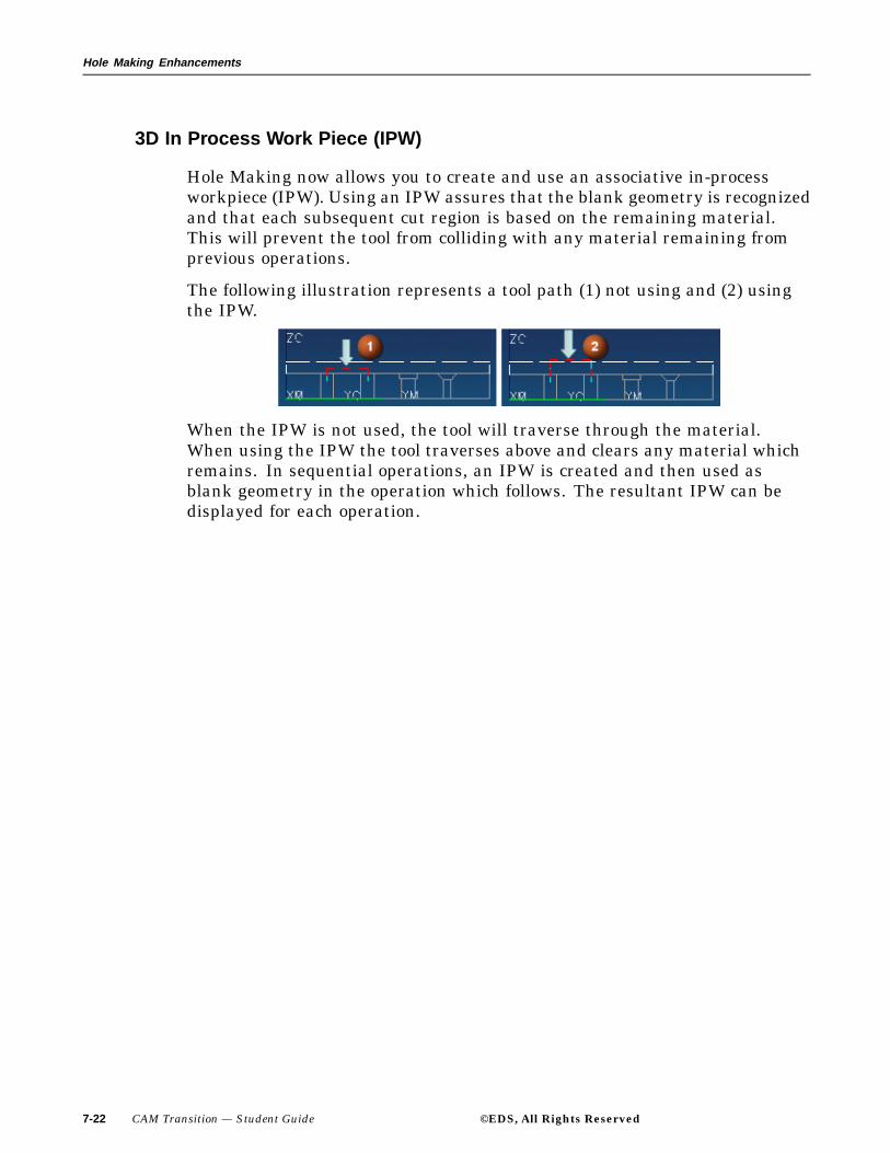
Hole Making Enhancements
3D In Process Work Piece (IPW)
Hole Making now allows you to create and use an associative in-processworkpiece (IPW). Using an IPW assures that the blank geometry is recognizedand that each subsequent cut region is based on the remaining material.This will prevent the tool from colliding with any material remaining fromprevious operations.
The following illustration represents a tool path (1) not using and (2) usingthe IPW.
When the IPW is not used, the tool will traverse through the material.When using the IPW the tool traverses above and clears any material whichremains. In sequential operations, an IPW is created and then used asblank geometry in the operation which follows. The resultant IPW can bedisplayed for each operation.
7-22 CAM Transition — Student Guide ©EDS, All Rights Reserved

Hole Making Enhancements
Activity: Using the IPW in Hole Making
In this activity you will first examine a Hole Making operation and observethat the tool could possibly collide with the work piece. You will then createand use an IPW that will prevent the tool from colliding with any materialthat may remain from previous operations.
Step 1: Open the part cat_hole_making_ipw.
If necessary, start Unigraphics NX 2.
Use File → Open.
Navigate to your parts folder and open the file.
Briefly examine the part.
Step 2: If necessary, enter the Manufacturing Application and displaythe Operation Navigator.
Choose Application → Manufacturing from the Menu bar.
Choose the Operation Navigator icon from the Resource
bar.
If necessary, change to the Geometry View of the OperationNavigatorand expand the objects.
©EDS, All Rights Reserved CAM Transition — Student Guide 7-23
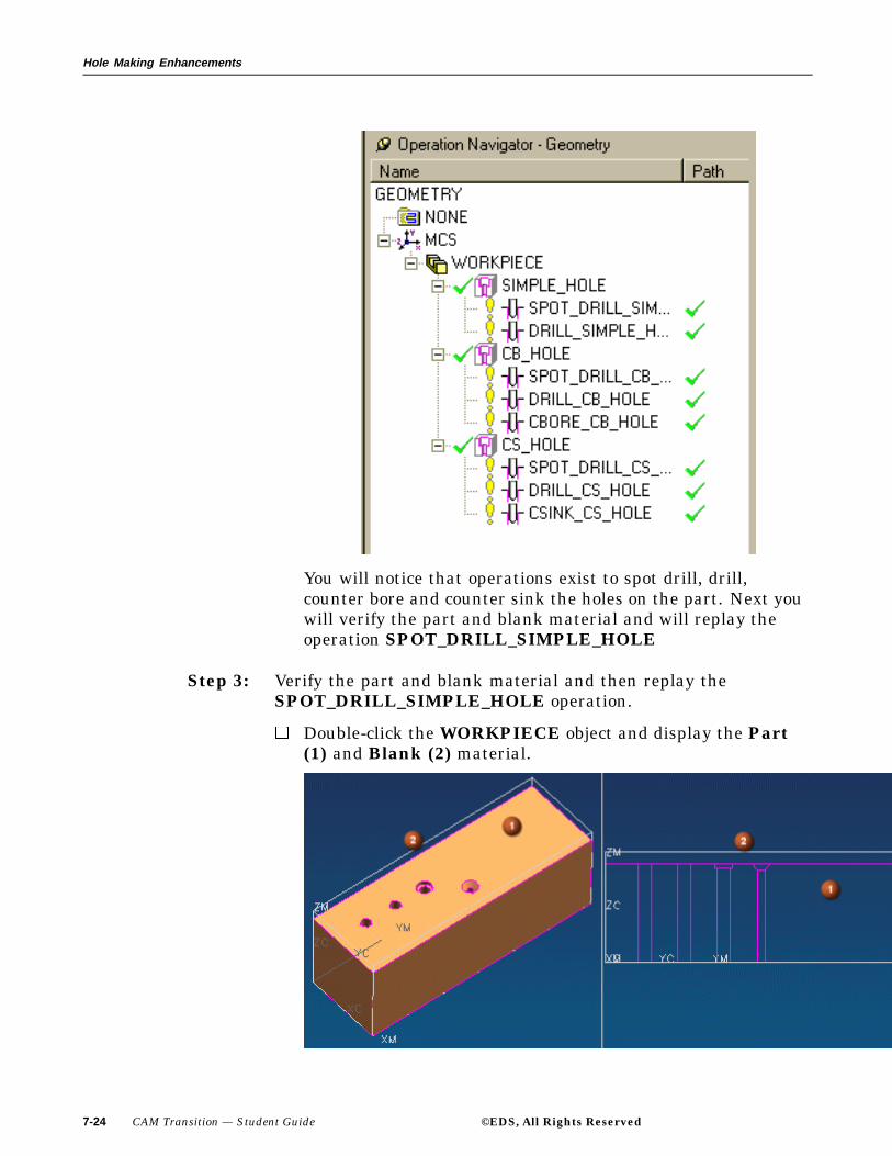
Hole Making Enhancements
You will notice that operations exist to spot drill, drill,counter bore and counter sink the holes on the part. Next youwill verify the part and blank material and will replay theoperation SPOT_DRILL_SIMPLE_HOLE
Step 3: Verify the part and blank material and then replay theSPOT_DRILL_SIMPLE_HOLE operation.
Double-click the WORKPIECE object and display the Part(1) and Blank (2) material.
7-24 CAM Transition — Student Guide ©EDS, All Rights Reserved

Hole Making Enhancements
The operation recognizes Blank geometry only if the IPW isutilized. In this example, the Blank geometry, which extendsabove the actual Part surface, is not recognized and the toolcollides with the Blank material. You will now replay thetool path, and observe how the tool collides with the Blankmaterial.
Choose OK on the MILL_GEOM dialog.
Highlight the SPOT_DRILL_SIMPLE_HOLE operation,using MB3, Replay the operation.
Note how the tool, when positioning from one hole to the next,does not retract high enough, to avoid colliding with the Blankmaterial. You will now activate the IPW, which will keep thetool from colliding with the Blank material.
The Use 3D IPW option must be customized intoeach HOLE_MAKING operation dialog.
Step 4: Incorporating and using the IPW.
Change to the Program Order view of the OperationNavigator and if necessary expand all objects.
©EDS, All Rights Reserved CAM Transition — Student Guide 7-25

Hole Making Enhancements
Highlight the SPOT_DRILL_SIMPLE_HOLE operation andusing MB3, select Object → Customize.
7-26 CAM Transition — Student Guide ©EDS, All Rights Reserved

Hole Making Enhancements
Choose Retract Distance On Tool Change from the ItemsUsed List of the Customize Dialog.
©EDS, All Rights Reserved CAM Transition — Student Guide 7-27

Hole Making Enhancements
This will be the area of the Hole_Making dialog in which theUse 3D IPW option will appear.
Choose Use 3D Workpiece from the Available Items List.
7-28 CAM Transition — Student Guide ©EDS, All Rights Reserved

Hole Making Enhancements
Choose the ADD arrow to move the Use 3D Workpiece optioninto the Items Used List.
©EDS, All Rights Reserved CAM Transition — Student Guide 7-29
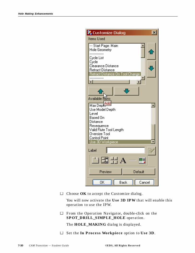
Hole Making Enhancements
Choose OK to accept the Customize dialog.
You will now activate the Use 3D IPW that will enable thisoperation to use the IPW.
From the Operation Navigator, double-click on theSPOT_DRILL_SIMPLE_HOLE operation.
The HOLE_MAKING dialog is displayed.
Set the In Process Workpiece option to Use 3D.
7-30 CAM Transition — Student Guide ©EDS, All Rights Reserved

Hole Making Enhancements
You will now regenerate the operation.
Choose the Generate icon.
©EDS, All Rights Reserved CAM Transition — Student Guide 7-31
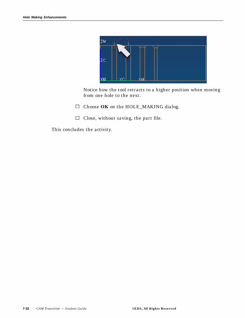
Hole Making Enhancements
Notice how the tool retracts to a higher position when movingfrom one hole to the next.
Choose OK on the HOLE_MAKING dialog.
Close, without saving, the part file.
This concludes the activity.
7-32 CAM Transition — Student Guide ©EDS, All Rights Reserved

Hole Making Enhancements
Maximum Cut Depth and Extended Length
Check Flute Length and Check Tool Length are parameters that areused to verify that the appropriate tools are retrieved into the part whenperforming tool queries from the tool library. Check Flute Length validatesthat the tools copied from the tool library have a flute length that is longenough for the required cut depth. Check Tool Length validates that thetools copied from the tool library have a tool length that is long enough toavoid collisions between the tool holder and adjacent walls of the part.
1. Cut Depth
2. Flute Length
3. Tool Length
Check Flute Length and Check Tool Length must be customized intothe HOLE_MAKING dialog.
©EDS, All Rights Reserved CAM Transition — Student Guide 7-33

Hole Making Enhancements
Activity: Maximum Cut Depth and Extended Length
In this activity you will first examine a Hole Making operation and observethat the tool holder will collide with the work piece since the tool does nothave enough length to drill thorough the part. You will then search the toollibrary for tools with appropriate tool lengths that can perform the requiredoperation with out colliding with the part.
Step 1: Open the part cat_hole_making_mx_ct_dp.
If necessary, start Unigraphics NX 2.
Use File → Open.
Navigate to your parts folder and open the file.
Briefly examine the part.
Step 2: If necessary, enter the Manufacturing Application and displaythe Operation Navigator.
Choose Application → Manufacturing from the Menu bar.
Choose the Operation Navigator icon from the Resource
bar.
If necessary, change to the Geometry View of the OperationNavigatorand expand the objects.
7-34 CAM Transition — Student Guide ©EDS, All Rights Reserved
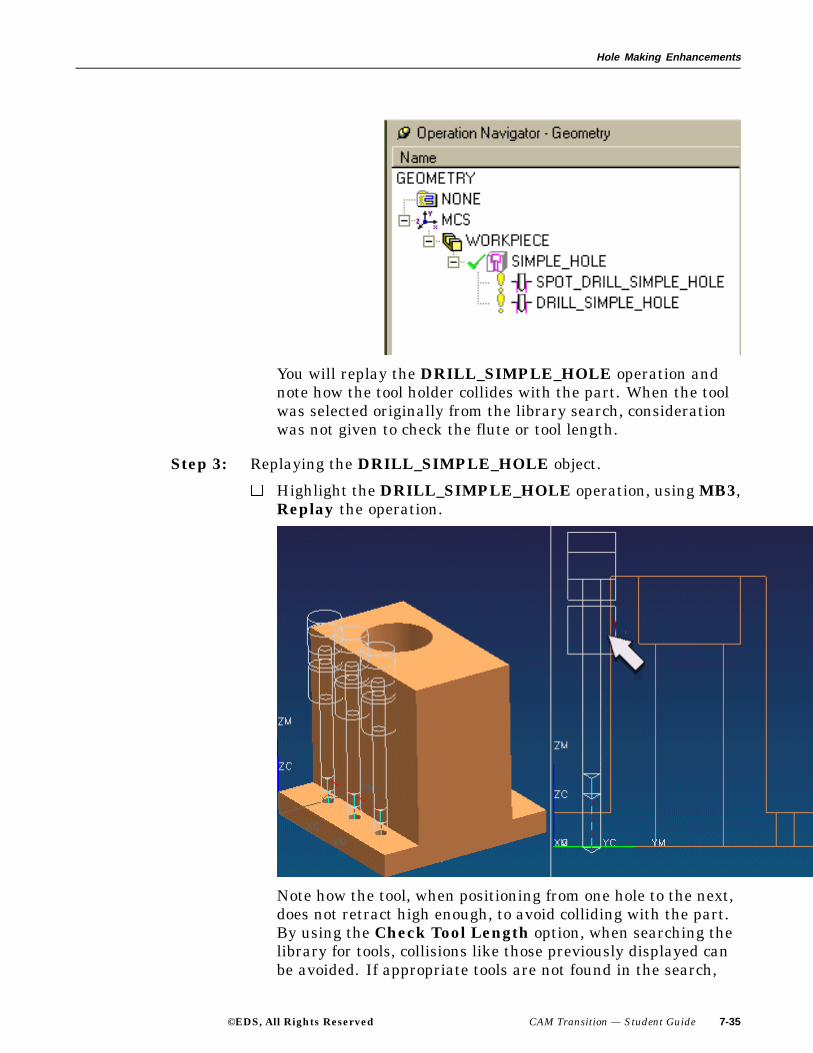
Hole Making Enhancements
You will replay the DRILL_SIMPLE_HOLE operation andnote how the tool holder collides with the part. When the toolwas selected originally from the library search, considerationwas not given to check the flute or tool length.
Step 3: Replaying the DRILL_SIMPLE_HOLE object.
Highlight the DRILL_SIMPLE_HOLE operation, using MB3,Replay the operation.
Note how the tool, when positioning from one hole to the next,does not retract high enough, to avoid colliding with the part.By using the Check Tool Length option, when searching thelibrary for tools, collisions like those previously displayed canbe avoided. If appropriate tools are not found in the search,
©EDS, All Rights Reserved CAM Transition — Student Guide 7-35

Hole Making Enhancements
you will be prompted to create a new tool(s). You will now usethe Check Flute Length and Check Tool Length options tosearch the tool library for proper length tools.
The Check Flute Length and Check ToolLength option must be customized into eachHOLE_MAKING operation dialog.
Step 4: Incorporating and using theCheck Flute Length and CheckTool Length options.
Highlight the DRILL_SIMPLE_HOLE operation. and usingMB3, select Object → Customize.
Choose Tool Class Query from the Items Used List of theCustomize Dialog.
7-36 CAM Transition — Student Guide ©EDS, All Rights Reserved

Hole Making Enhancements
This will be the area of the Hole_Making dialog in which theCheck Flute Length and Check Tool Length option willappear.
Choose Valid Flute Tool Length from the Available ItemsList.
©EDS, All Rights Reserved CAM Transition — Student Guide 7-37

Hole Making Enhancements
Choose the ADD arrow to move the Valid Flute Tool Lengthoption into the Items Used List.
7-38 CAM Transition — Student Guide ©EDS, All Rights Reserved

Hole Making Enhancements
Choose OK to accept the Customize dialog.
You will now retrieve tools using the Check Flute Lengthand Check Tool Length when querying the library.
From the Operation Navigator, double-click on theDRILL_SIMPLE_HOLE operation.
The HOLE_MAKING dialog is displayed.
©EDS, All Rights Reserved CAM Transition — Student Guide 7-39

Hole Making Enhancements
Choose the Groups tab at the top of the HOLE_MAKINGdialog.
The Check Flute Length and Check Tool Length optionsare turned off. You will turn these options on and then querythe library for the proper tooling.
7-40 CAM Transition — Student Guide ©EDS, All Rights Reserved
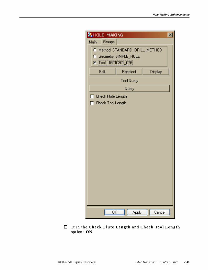
Hole Making Enhancements
Turn the Check Flute Length and Check Tool Lengthoptions ON.
©EDS, All Rights Reserved CAM Transition — Student Guide 7-41

Hole Making Enhancements
Choose Reselect.
The Tool Search dialog is displayed with the proper tool.
Choose the tool from the list and then choose OK on theSearch Result dialog.
Choose the Main tab from the top of the HOLE_MAKINGdialog.
Choose the Generate icon.
7-42 CAM Transition — Student Guide ©EDS, All Rights Reserved

Hole Making Enhancements
Notice how the extended tool length now clears the part.
Choose OK on the HOLE_MAKING dialog.
Close, without saving, the part file.
This concludes the activity.
©EDS, All Rights Reserved CAM Transition — Student Guide 7-43

Hole Making Enhancements
Multiple Selection
Features can be selected using the Class Selection dialog when appendingor removing them from a feature group. This allows the selection of severalfeatures at once.
7-44 CAM Transition — Student Guide ©EDS, All Rights Reserved

Hole Making Enhancements
Inch and Metric Availability within Tool Query
Units options have been added to the Query From Method dialog. Thesetoggle buttons allow you to specify Inches or Millimeters as the units of thetools to be retrieved into the part when performing queries from the toollibrary. This allows you to search for metric tools in an inch part and inchtools in a metric part. If the retrieved tool has a different unit from that ofthe part, the tool parameter values are converted into the units of the part.This setting is applicable only to queries that are being used in the ASCII tooldatabase. To specify the Units query parameter double-click on a MachiningMethod object in the Operation Navigator. Select Query and then selecteither the Inches or Millimeters button.
Then accept the Query from the Method dialog. This setting will be savedwith the Machining Method object selected and is then applied to thatobject when the query is executed and when subsequent tools are retrieved.
To execute a tool query, double-click an operation inside the MachiningMethod object you just edited. Select the Groups tab. Turn the Tool buttonon and choose Reselect. Then select the tool you to retrieve from the SearchResult dialog. If the query cannot find any tools in the specified Inches orMillimeters library, then the Reselect Tool dialog will be display.
©EDS, All Rights Reserved CAM Transition — Student Guide 7-45

Hole Making Enhancements
Summary
The Hole Making Module greatly simplifies the process of making holes,regardless of the type of application. The following functions adds to therobustness and efficiency of using this module:
• Alternate Groups of Operations
• Cut Area
• Feature Recognition
• Feature Status
• Holder Types
• 3D In Process Work Piece (IPW)
• Maximum Cut Depth and Extended Length
• Multiple Selection
• Inch and Metric Availability Within Tool Query
7-46 CAM Transition — Student Guide ©EDS, All Rights Reserved

Lesson
8 Integration, Simulation andVerification Enhancements
Purpose
The purpose of this lesson is to become familiar with the new Integration,Simulation and Verification module used produce accurate simulations ofmachine tools machining your parts.
Objectives
In this lesson, you will:
• Overview the features of the Integration, Simulation and Verification(IS&V) module.
• Review Visualize.
• Overview Simulation and Advanced Simulation.
• Review the Machine Tool Builder, Machine Tool Driver and SetupConfigurator components.
• ”Walk through” a typical simulation.
©EDS, All Rights Reserved CAM Transition — Student Guide 8-1

Integration, Simulation and Verification Enhancements
Integration, Simulation and Verification Overview
The Integrated Simulation and Verification Module (IS&V) allows youto simulate a machine tool with an actual piece part, giving you an overviewof the entire machining process. The simulation process animates the exactmachine tool motions, taking into account controller functions and cuttingtool configurations.
Collision checking allows collision detection between machine components,fixtures, tool, part, and the in-process work piece. You may also view machinecontroller functions including macros, subroutine calls, cycles, and functionalM, G and H commands.
IS&V can improve the quality of machining processes by allowing thecomparison of the designed part to the part which is being manufactured.Reduction in cost can also be obtained by the elimination of expensive andtime-consuming dry runs; reduction in manual operator intervention; andthe reduce risk of expensive damage to machine tools, fixtures and parts bythe elimination of collisions.
IS&V consists of the following components:
• Visualize
• Simulation
• Advanced Simulation
• Machine Tool Builder
• Machine Tool Driver
• Setup configurator
8-2 CAM Transition — Student Guide ©EDS, All Rights Reserved

Integration, Simulation and Verification Enhancements
©EDS, All Rights Reserved CAM Transition — Student Guide 8-3
Integration, Simulation and Verification Enhancements
Visualize
• Basic level of visualization of tool paths
• Tool ONLY moves, no kinematic model of machine tool
• Performs gouge checking and collision with part and IPW
• Display of material removal is 2D only
• Optionally produces IPW used in roughing
8-4 CAM Transition — Student Guide ©EDS, All Rights Reserved
Integration, Simulation and Verification Enhancements
Simulation
• Basic level of simulation of tool paths
• Uses kinematic model of machine tool — simulations shows configurationof machine including head and table movement
• Common machine tool library
• Common controller library
• Shows collision detection with associated components
©EDS, All Rights Reserved CAM Transition — Student Guide 8-5

Integration, Simulation and Verification Enhancements
Advanced Simulation
• Uses kinematic model of machine tool — simulations shows configurationof machine including head and table movement.
• Includes Machine Tool Builder capabilities
• Provides gouge checking and collision detection
• Provides methods to configure the manner of simulation (controllerconfiguration)
• Includes interface to Post Builder — enhanced, to generate machinecontroller drivers automatically
• Provides interface to machine tool libraries
• Provides the ability to simulate existing machine G & M codes (reversepostprocessing)
8-6 CAM Transition — Student Guide ©EDS, All Rights Reserved

Integration, Simulation and Verification Enhancements
Machine Tool Builder
• Used to build a Machine Tool or device
• Uses Geometric model, created as an assembly
• Builds a Kinematic model of machine tool members
• Defines a Mounting model
• Animates motion along machine axis for testing purposes
• May edit model through associated kinematics tree manipulation
©EDS, All Rights Reserved CAM Transition — Student Guide 8-7

Integration, Simulation and Verification Enhancements
Machine Tool Driver
• Generates motion control program and emulates CNC controller
• Accurate path based on machine tool configuration
• Handles specific machine tool features including macros, cycles andsubroutines
• Can be customized using TCL scripting language
• Text and graphic feedback initiated by events
The Machine Tool Driver (MTD) creates the CNC program that emulatesthe CNC controller. The CNC controller emulator (or Virtual NC controller) isa programmable interface that instructs the machine tool model on actualmovements and how those movements are then displayed. Any motion and
8-8 CAM Transition — Student Guide ©EDS, All Rights Reserved

Integration, Simulation and Verification Enhancements
feedback displayed during machine tool simulation is controlled by thededicated MTD. For comparison purposes, the MTD is analogous to themachine tool simulator as the CNC controller is analogous to the machinetool that it controls. For each machine tool in the machine tool library thereis a MTD driver available (eleven generic MTD’s come standard with NX2). For creating an MTD for a new machine tool, you can modify a genericdriver to work with that machine. MTD’s are written in the Tcl scriptinglanguage but also may be developed in higher level languages such as C++.MTD,s can emulate special cycles, User Defined Events (UDE’s), macrosand other CNC controller dependent functions that the Manufacturingapplication does not support.
©EDS, All Rights Reserved CAM Transition — Student Guide 8-9

Integration, Simulation and Verification Enhancements
Setup Configurator
• Similar functionality to machine tool builder
• Active in Manufacturing application only
• Used for mounting work piece and fixtures machine tool
• Also used for defining machine state
8-10 CAM Transition — Student Guide ©EDS, All Rights Reserved

Integration, Simulation and Verification Enhancements
Summary
In this lesson you :
• Reviewed the components that comprise the Integration, Simulationand Verification module.
©EDS, All Rights Reserved CAM Transition — Student Guide 8-11

Appendix
A V18 to NX What’s New in CAM
CAM User Interface
• Drag and Drop multiple objects
• Status Icons in columns
• The Name, Toolchange, Path and IPW column
• Third Mouse Button Options
©EDS, All Rights Reserved CAM Transition — Student Guide A-1

V18 to NX What’s New in CAM
General Milling Enhancements
• 2D Contact Contour Machining
• IPW for Fixed Axis milling
• Custom Boundary Data for milling
• Scallop Height control
• Face Milling Blank overhang
• Face Milling Tool Run-off
• Face Milling — Controlling automatic engages directly into the part
• High Speed Machining
A-2 CAM Transition — Student Guide ©EDS, All Rights Reserved

V18 to NX What’s New in CAM
Hole Making
• Machining Environment
• Analyzing existing features and objects
• Template part files for Hole Making
• The Sketch Constraints Toolbar
• Creating Hole Making operations
• Optimizing Hole Making tool paths
©EDS, All Rights Reserved CAM Transition — Student Guide A-3

V18 to NX What’s New in CAM
Turning
• Multiple Spindles
• Specifying stock within Method Group objects
• Specifying Automatic Spindle direction
• Manual identification of the Lathe work plane
• Custom boundary data
• Ramping cut pattern
• Automatic Start Point and Total Depth by Diameter
• Drilling Depth to Shoulder
• Teach Mode
A-4 CAM Transition — Student Guide ©EDS, All Rights Reserved

PLM SOLUTIONS STUDENT PROFILE
In order to stay in tune with our customers we ask for some background information. This information will be kept confidential and will not be shared with anyone outside of Education Services.
Please “ Print” …
Your Name U.S. citizen Yes No Course Title/Dates / thru Hotel/motel you are staying at during your training Planned departure time on last day of class Employer Location Your title and job responsibilities / Industry: Auto Aero Consumer products Machining Tooling Medical Other Types of products/parts/data that you work with Reason for training Please ver ify/add to this list of training for Unigraphics, I-deas, Imageware, Teamcenter Mfg., Teamcenter Eng. (I-Man), Teamcenter Enterprise (Metaphase), or Dimensional Mgmt./Visualization. Medium means Instructor-lead (IL ), On-line (OL ), or Self-paced (SP) Software From Whom When Course Name Medium
Other CAD/CAM/CAE /PDM software you have used
Please “ check”�
your ability/knowledge in the following… Subject CAD modeling CAD assemblies CAD drafting CAM CAE PDM – data management PDM – system management
None o o o o o o o
Novice o o o o o o o
Intermediate o o o o o o o
Advanced o o o o o o o
Platform (operating system) Thank you for you participation and we hope your training experience will be an outstanding one.

This page left blank intentionally.

NX CAM Transition - Agenda
Hour 1
• Overview
• Lesson 2. Usability
• Lesson 3. Visualization
Hour 2
• Lesson 4. General CAM Enhancements
• Lesson 5. Wire EDM Enhancements
Hour 3
• Lesson 6. General Milling Enhancements
Hour 4
• Lesson 6. General Milling Enhancements
Hour 5
• Lesson 7.Turning Enhancements
• Lesson 8. Hole Making Enhancements
Hour 6
• Lesson 8. Hole Making Enhancements
• Integration, Simulation and Verification

This page left blank intentionally.
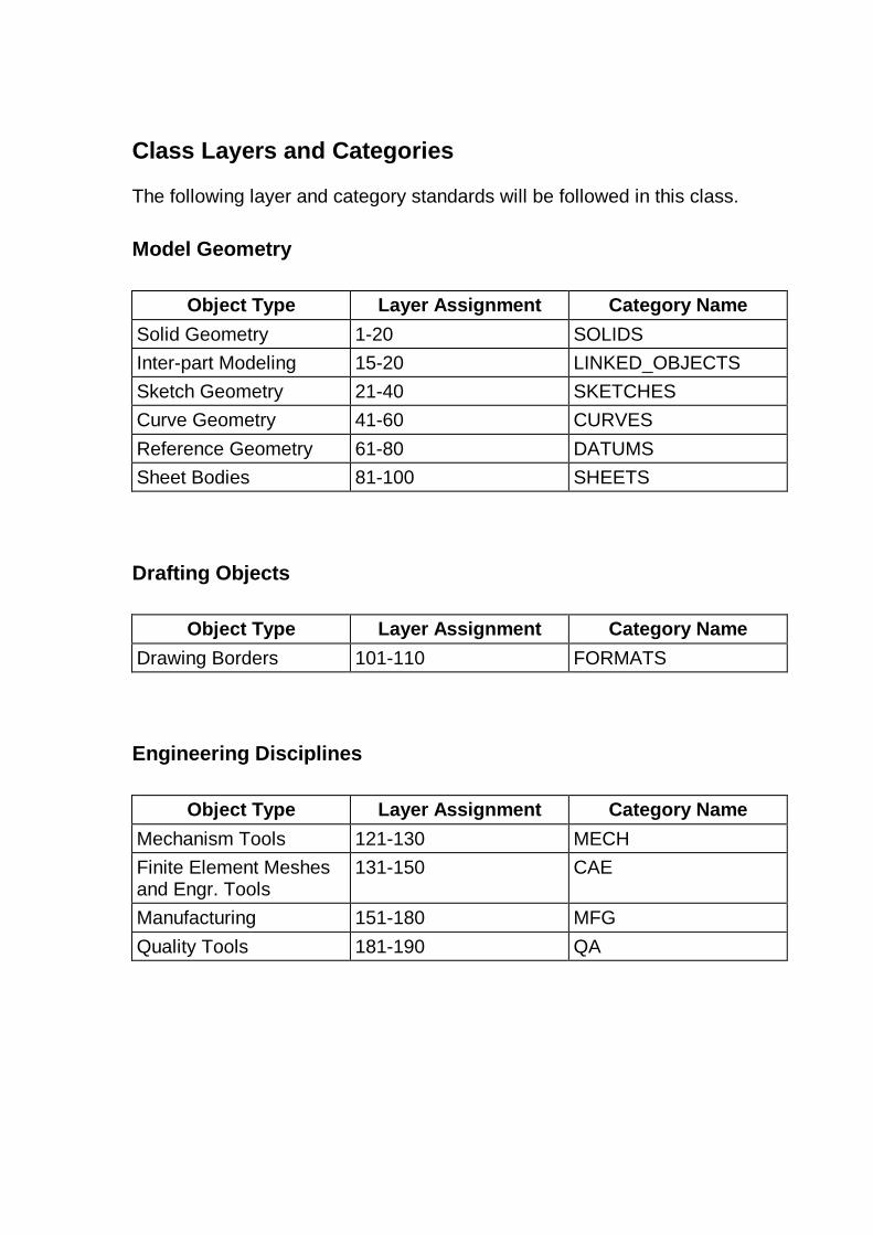
Class Layers and Categories
The following layer and category standards will be followed in this class.
Model Geometry
Object Type Layer Assignment Category Name
Solid Geometry 1-20 SOLIDS
Inter-part Modeling 15-20 LINKED_OBJECTS
Sketch Geometry 21-40 SKETCHES
Curve Geometry 41-60 CURVES
Reference Geometry 61-80 DATUMS
Sheet Bodies 81-100 SHEETS
Drafting Objects
Object Type Layer Assignment Category Name
Drawing Borders 101-110 FORMATS
Engineering Disciplines
Object Type Layer Assignment Category Name
Mechanism Tools 121-130 MECH
Finite Element Meshes and Engr. Tools
131-150 CAE
Manufacturing 151-180 MFG
Quality Tools 181-190 QA

This page left blank intentionally.

Hot Key Chart
Hot Key
Function Hot Key Function
Ctrl-A Ctrl-N File, New
Ctrl-B Edit, Blank Ctrl-O File, Open
Ctrl-C Copy Ctrl-P File, Plot
Ctrl-D Delete Ctrl-Q
Ctrl-E Tools, Expression Ctrl-R View, Operation, Rotate (full menu)
Ctrl-F Fit View Ctrl-S File, Save
Ctrl-G Grip Execute Ctrl-T Edit, Transform
Ctrl-H Ctrl-U Execute User Function
Ctrl-I Information, Object Ctrl-V Paste
Ctrl-J Edit, Object Display Ctrl-W Application, Gateway
Ctrl-K Ctrl-X Cut
Ctrl-L Format, Layer Settings Ctrl-Y
Ctrl-M Application, Modeling Ctrl-Z Edit, Undo

Ctrl-Shift-A File, Save As Ctrl-Shift-N Format, Layout, New
Ctrl-Shift-B Edit, Blank, Reverse Blank All
Ctrl-Shift-O Format, Layout, Open
Ctrl-Shift-C View, Curvature Graph Ctrl-Shift-P Tools, Macro, Playback
Ctrl-Shift-D Drafting Ctrl-Shift-Q Quick Shaded Image
Ctrl-Shift-E Ctrl-Shift-R Tools, Macro, Record
Ctrl-Shift-F Format, Layout, Fit All Views
Ctrl-Shift-S Toolsm Macro, Step
Ctrl-Shift-G Debug Grip Ctrl-Shift-T Preferences, Selection
Ctrl-Shift-H High Quality Image Ctrl-Shift-U Edit, Blank, Unblank All Of Part
Ctrl-Shift-I Ctrl-Shift-V Format, Visible In View
Ctrl-Shift-J Preferences, Object Ctrl-Shift-W
Ctrl-Shift-K Edit, Blank, Unblank Selected
Ctrl-Shift-X
Ctrl-Shift-L Ctrl-Shift-Y
Ctrl-Shift-M Ctrl-Shift-Z View, Operation, Zoom (full menu)
Alt-Tab Toggles Application Ctrl-Alt-B Tools, Boundary
Alt-F4 Closes Active Window Ctrl-Alt-C Tools, CLSF
F1 Help on Context Ctrl-Alt-M Application Manufacturing
F3 View Current Dialog Ctrl-Alt-N Tools, Unisim
F4 Information Window Ctrl-Alt-W Application Assemblies
F5 Refresh Ctrl-Alt-X Tools, Lathe Cross-Section
F6 Quick Zoom
F7 Quick Rotate

PLM Solutions Evaluation – Delivery
NX 2 CAM Transition, Course #TR11015 Dates thru
Please share your opinion in all of the following sections with a “check” in the appropriate box:
Instructor : �
I f there were 2 instructors, please evaluate the 2nd instructor with “ X’s”
Instructor : � 1. …clear ly explained the course objectives 2. …was knowledgeable about the subject 3. …answered my questions appropr iately 4. … encouraged questions in class 5. …was well spoken and a good communicator 6. …was well prepared to deliver the course 7. …made good use of the training time 8. …conducted themselves professionally 9. …used examples relevant to the course and audience 10. …provided enough time to complete the exercises 11. …used review and summary to emphasize impor tant information 12. …did all they could to help the class meet the course objectives
Comments on overall impression of instructor (s):
Overall impression of instructor (s) Poor Excellent Suggestions for improvement of course delivery:
What you liked best about the course delivery:
Class Logistics: 1. The training facilities were comfor table, clean, and provided a good learning
environment 2. The computer equipment was reliable 3. The software per formed proper ly 4. The overhead projection unit was clear and working proper ly 5. The registration and confirmation process was efficient
Hotels: (We try to leverage this information to better accommodate our customers) 1. Name of the hotel Best hotel I ’ve stayed at
2. Was this hotel recommended dur ing your registration process? YES NO
3. Problem? (br ief descr iption)
SEE BACK
STR
ON
GL
Y
DIS
AG
RE
E
DIS
AG
RE
E
SOM
EW
HA
T
DIS
AG
RE
E
SOM
EW
HA
T
AG
RE
E
AG
RE
E
STR
ON
GL
Y
AG
RE
E

PLM Solutions Evaluation - Courseware NX 2 CAM Transition
Dates thru
Please share your opinion for all of the following sections with a “check” in the appropriate box:
Mater ial: 1. The training mater ial suppor ted the course and lesson objectives 2. The training mater ial contained all topics needed to complete the projects 3. The training mater ial provided clear and descr iptive directions 4. The training mater ial was easy to read and understand 5. The course flowed in a logical and meaningful manner 6. How appropr iate was the length of the course relative to the mater ial? Too shor t Too long Just r ight
Comments on Course and Mater ial:
Overall impression of course Poor Excellent
Student: 1. I met the prerequisites for the class (I had the skills I needed) 2. My objectives were consistent with the course objectives 3. I will be able to use the skills I have learned on my job 4. My expectations for this course were met 5. I am confident that with practice I will become proficient
Name (optional): Location/room
Please “ check” this box if you would like your comments featured in our training publications. (Your name is required at the bottom of this form)
Please “ check” this box if you would like to receive more information on our other courses and services. (Your name is required at the bottom of this form)
Thank you for your business. We hope to continue to provide your training and personal development for the future.
STR
ON
GL
Y
DIS
AG
RE
E
DIS
AG
RE
E
SOM
EW
HA
T
DIS
AG
RE
E
SOM
EW
HA
T
AG
RE
E
AG
RE
E
STR
ON
GL
Y
AG
RE
E