UNIFIED FACILITIES CRITERIA (UFC) - Whole Building Design ... · The Unified Facilities Criteria...
143
UFC 3-430-01FA 25 July 2003 UNIFIED FACILITIES CRITERIA (UFC) HEATING AND COOLING DISTRIBUTION SYSTEMS APPROVED FOR PUBLIC RELEASE; DISTRIBUTION UNLIMITED
Transcript of UNIFIED FACILITIES CRITERIA (UFC) - Whole Building Design ... · The Unified Facilities Criteria...

UFC 3-430-01FA 25 July 2003
UNIFIED FACILITIES CRITERIA (UFC)
HEATING AND COOLING DISTRIBUTION SYSTEMS
APPROVED FOR PUBLIC RELEASE; DISTRIBUTION UNLIMITED
UFC 3-430-01FA 25 July 2003
1
UNIFIED FACILITIES CRITERIA (UFC)
HEATING AND COOLING DISTRIBUTION SYSTEMS
Any copyrighted material included in this UFC is identified at its point of use. Use of the copyrighted material apart from this UFC must have the permission of the copyright holder. U.S. ARMY CORPS OF ENGINEERS (Preparing Activity) NAVAL FACILITIES ENGINEERING COMMAND AIR FORCE CIVIL ENGINEER SUPPORT AGENCY Record of Changes (changes are indicated by \1\ ... /1/) Change No. Date Location
This UFC supersedes TI 810-32 dated 10 January 2002. The text of this UFC is the text of TI 810-32. The format of this document does not conform to UFC 1-300-01; however, it will be reformatted at the next revision.

UFC 3-430-01FA 25 July 2003
2
FOREWORD \1\ The Unified Facilities Criteria (UFC) system is prescribed by MIL-STD 3007 and provides planning, design, construction, sustainment, restoration, and modernization criteria, and applies to the Military Departments, the Defense Agencies, and the DoD Field Activities in accordance with USD(AT&L) Memorandum dated 29 May 2002. UFC will be used for all DoD projects and work for other customers where appropriate. All construction outside of the United States is also governed by Status of forces Agreements (SOFA), Host Nation Funded Construction Agreements (HNFA), and in some instances, Bilateral Infrastructure Agreements (BIA.) Therefore, the acquisition team must ensure compliance with the more stringent of the UFC, the SOFA, the HNFA, and the BIA, as applicable. UFC are living documents and will be periodically reviewed, updated, and made available to users as part of the Services’ responsibility for providing technical criteria for military construction. Headquarters, U.S. Army Corps of Engineers (HQUSACE), Naval Facilities Engineering Command (NAVFAC), and Air Force Civil Engineer Support Agency (AFCESA) are responsible for administration of the UFC system. Defense agencies should contact the preparing service for document interpretation and improvements. Technical content of UFC is the responsibility of the cognizant DoD working group. Recommended changes with supporting rationale should be sent to the respective service proponent office by the following electronic form: Criteria Change Request (CCR). The form is also accessible from the Internet sites listed below. UFC are effective upon issuance and are distributed only in electronic media from the following source: • Whole Building Design Guide web site http://dod.wbdg.org/. Hard copies of UFC printed from electronic media should be checked against the current electronic version prior to use to ensure that they are current. AUTHORIZED BY: ______________________________________ DONALD L. BASHAM, P.E. Chief, Engineering and Construction U.S. Army Corps of Engineers
______________________________________DR. JAMES W WRIGHT, P.E. Chief Engineer Naval Facilities Engineering Command
______________________________________ KATHLEEN I. FERGUSON, P.E. The Deputy Civil Engineer DCS/Installations & Logistics Department of the Air Force
______________________________________Dr. GET W. MOY, P.E. Director, Installations Requirements and Management Office of the Deputy Under Secretary of Defense (Installations and Environment)

TI 810-32 10 January 2002
Technical Instructions
HEATING AND COOLING DISTRIBUTION SYSTEMS
Headquarters U.S. Army Corps of Engineers Engineering Division Directorate of Military Programs

CEMP-E TI 810-32
10 January 2002
TECHNICAL INSTRUCTIONS
HEATING AND COOLING DISTRIBUTION SYSTEMS
Any copyrighted material included in this document is identified at its point of use. Use of the copyrighted material apart from this document must have the permission of the copyright holder.
Approved for public release; distribution is unlimited.
This document reissued 10 January 2002. Record of Changes (changes indicated \1\…/1/ ) No. Date Location 1 7 March 2002 Pages 4-1, 4-2, 5-1, and C-1 Table 4-2 Figures (editorial – changes not marked) 3-1 thru 3-28, 4-1, and 4-3 2 30 Sept 2002 Page 1-1 Figures (editorial – changes not marked) 3-14, 3-28, 4-4, 4-5, 4-17, and 7-7

CEMP-E TI 810-32 30 August 1999
Reissued 10 January 2002
FOREWORD
These technical instructions (TI) provide design and construction criteria and apply to all U.S. Army Corps of Engineers (USACE) commands having military construction responsibilities. TI will be used for all Army projects and for projects executed for other military services or work for other customers where appropriate. TI are living documents and will be periodically reviewed, updated, and made available to users as part of the HQUSACE responsibility for technical criteria and policy for new military construction. CEMP-ED is responsible for administration of the TI system; technical content of TI is the responsibility of the HQUSACE element of the discipline involved. Recommended changes to TI, with rationale for the changes, should be sent to HQUSACE, ATTN: CEMP-ED, 20 Massachusetts Ave., NW, Washington, DC 20314-1000. TI are effective upon issuance. TI are distributed only in electronic media through the TECHINFO Internet site http://www.hnd.usace.army.mil /techinfo/index.htm and the Construction Criteria Base (CCB) systems maintained by the National Institute of Building Sciences at Internet Site http://www.nibs.org/ccb/. Hard copies of these instructions produced by the user from the electronic media should be checked against the current electronic version prior to use to assure that the latest instructions are used. FOR THE COMMANDER:
DWIGHT A. BERANEK, P.E.
Chief, Engineering and Construction Division Directorate of Military Programs
CEMP-E TI 810-32 10 January 2002
i
HEATING AND COOLING DISTRIBUTION SYSTEMS
Table of Contents
Page CHAPTER 1. GENERAL INFORMATION
Paragraph 1-1. PURPOSE AND SCOPE.............................................................................. 1-1 1-2. APPLICABILITY............................................................................................... 1-1 1-3. REFERENCES............................................................................................... 1-1 1-4. EXCEPTIONS................................................................................................. 1-1 1-5. DEFINITIONS.................................................................................................. 1-1
CHAPTER 2. SYSTEM SELECTION
Paragraph 2-1. GENERAL .................................................................................................. 2-1 2-2. DISTRIBUTION MEDIA SELECTION ........................................................... 2-1
2-3. SYSTEM TYPES ......................................................................................... 2-1 2-4. SYSTEMS SELECTION ............................................................................... 2-2
CHAPTER 3. GENERAL DISTRIBUTION SYSTEM DESIGN
Paragraph 3-1. GENERAL .................................................................................................... 3-1 3-2. SITE SOIL SURVEY..................................................................................... 3-1 3-3. UTILITY INVESTIGATION ............................................................................. 3-1 3-4. SYSTEM LAYOUT PLAN/PROFILE ............................................................. 3-1 3-5. EXPANSION COMPENSATION ................................................................... 3-2 3-6. VALVE MANHOLES ...................................................................................... 3-3 ( Page 3-7 not used)
CHAPTER 4. HEAT DISTRIBUTION SYSTEMS IN CONCRETE TRENCHES
Paragraph 4-1. GENERAL .................................................................................................... 4-1 4-2. SYSTEM DESIGN ........................................................................................ 4-1 4-3. GENERAL CONSIDERATIONS ................................................................... 4-3
CHAPTER 5. PRE-ENGINEERED UNDERGROUND HEAT DISTRIBUTION SYSTEM
Paragraph 5-1. GENERAL..................................................................................................... 5-1 5-2. MANUFACTURER'S RESPONSIBILITY....................................................... 5-1 5-3. PROJECT DESIGNER'S RESPONSIBILITY............................................... 5-2
CHAPTER 6. PREFABRICATED UNDERGROUND HEATING/COOLING DISTRIBUTION SYSTEM Paragraph 6-1. GENERAL .................................................................................................... 6-1 6-2. SYSTEM DESIGN......................................................................................... 6-1 CHAPTER 7. ABOVEGROUND HEAT DISTRIBUTION SYSTEM Paragraph 7-1. GENERAL .................................................................................................... 7-1 7-2. SYSTEM DESIGN........................................................................................ 7-1

CEMP-E TI 810-32 10 January 2002
ii
CHAPTER 8. SPECIAL CONSIDERATIONS Paragraph 8-1. GENERAL .................................................................................................... 8-1 8-2. STEAM SYSTEMS....................................................................................... 8-1 8-3. HTHW SYSTEMS ........................................................................................ 8-3 8-4. LTHW and CW SYSTEMS .......................................................................... 8-3 APPENDIX A. REFERENCES ...................................................................................................A-1 APPENDIX B. PRESSURE DROP vs. FLOW CHART .............................................................B-1 APPENDIX C. CONDENSATION LOAD CALCULATIONS (NORMAL) .....................................C-1 APPENDIX D. CONDENSATION LOAD CALCULATIONS (STARTUP)....................................D-1
List of Figures Title Page
Figure 3-1. Typical valve manhole plan........................................................................... 3-8
3-2. Access Ladder detail..................................................................................... 3-9 3-3. Typical isolation flange detail....................................................................... 3-10 3-4. Typical valve/piping support detail............................................................... 3-11 3-5. Valve manhole elevation and section.......................................................... 3-12 3-6. Raised cover plate design .......................................................................... 3-13 3-7. Section A-A of raised cover plate ................................................................ 3-14 3-8. Section B-B of raised cover plate................................................................ 3-15 3-9. Section C-C of raised cover plate ............................................................... 3-16 3-10. Detail of raised cover plate......................................................................... 3-17 3-11. Lifting lug detail ........................................................................................... 3-18 3-12. Handle detail ............................................................................................... 3-19 3-13. Notes for raised cover plate ....................................................................... 3-20 3-14. Typical support cover plan (grate support) ............................................... 3-21 3-15. Detail of angle support for grating ............................................................. 3-22 3-16. Detail of structural support for grating....................................................... 3-23 3-17. Grating support steel locations.................................................................. 3-24 3-18. Detail of checker plate cover..................................................................... 3-25 3-19. Typical concrete cover plan ...................................................................... 3-26 3-20. Concrete cover details .............................................................................. 3-27 3-21. Gooseneck detail....................................................................................... 3-28 3-22. Valve manhole floor drain detail................................................................. 3-29 3-23. Remote sump basin.................................................................................. 3-30 3-24. Sump basin cover detail............................................................................ 3-31 3-25. Sump basin electrical details .................................................................... 3-32 3-26. Sump pump wiring diagram ...................................................................... 3-33 3-27. Valve manhole sump electrical details ...................................................... 3-34 3-28. Casing wall penetration detail.................................................................... 3-35 (Page 3-36 not used) 4-1. Free pipe support detail................................................................................. 4-4 4-2. Guided pipe support detail............................................................................. 4-5 4-3. Pipe anchor detail.......................................................................................... 4-6 4-4. Pipe support channel..................................................................................... 4-7 4-5. Trench dimension section............................................................................. 4-8

CEMP-E TI 810-32 10 January 2002
iii
4-6. Construction joint detail ................................................................................. 4-9 4-7. Typical trench section ................................................................................. 4-10 4-8. Trench corner detail .................................................................................... 4-11 4-9. Typical lifting devices................................................................................... 4-12 4-10. Typical trench road crossing..................................................................... 4-13 4-11. Trench crossing with curb and gutter ....................................................... 4-14 4-12. Trench crossing with drain pan................................................................. 4-15 4-13. Parking lot crossing; exposed top ............................................................. 4-16 4-14. Parking lot crossing; covered top.............................................................. 4-17 4-15. Sidewalk transverse section detail............................................................ 4-18 4-16. Expansion loop detail................................................................................. 4-19 4-17. Trench cover joint detail ............................................................................ 4-20 4-18. Access cover detail ................................................................................... 4-21 4-19. Vent and drain details ................................................................................ 4-22 5-1. Two-casing system detail ............................................................................. 5-4 5-2. Single casing system detail........................................................................... 5-5 5-3. Casing, vent, and drain detail ........................................................................ 5-6 7-1. Typical low profile support detail ................................................................... 7-3 7-2. Typical anchor pipe support .......................................................................... 7-4 7-3. Typical free pipe support ............................................................................... 7-5 7-4. Typical guided pipe support........................................................................... 7-6 7-5. Typical high profile base detail ...................................................................... 7-7 7-6. Typical pipe guide detail ................................................................................ 7-8 7-7. Typical pipe anchor detail.............................................................................. 7-9 7-8. Valve manhole top penetration detail........................................................... 7-10 8-1. Trap station layout schematic ....................................................................... 8-5 8-2. Accumulator detail......................................................................................... 8-6 8-3. Duplex condensate pump set connection detail ........................................... 8-7 8-4. Condensate cooling system for non-metallic pipe detail .............................. 8-8 8-5. Non-metallic pipe system anchor detail ........................................................ 8-9
List of Tables Title Page
Table 3-1. Valve manhole clearances......................................................................... 3-37 3-2. Valve manhole reinforcing steel sizes ....................................................... 3-38 3-3. Sump pump checklist................................................................................ 3-39 4-1. Channel support schedule......................................................................... 4-23 4-2. Support spacing schedule ......................................................................... 4-24 4-3. Trench dimension schedule ...................................................................... 4-25 4-4. Expansion loop schedule........................................................................... 4-25 8-1. Pipe sizing guidelines for condensate return systems.............................. 8-10
CEMP-E TI 810-32 10 January 2002
1-1
CHAPTER 1
GENERAL INFORMATION
1-1. PURPOSE AND SCOPE. This document provides criteria and guidance for the design and construction of heating and cooling distribution systems and supplements information in the "Notes to the Designer" of the guide specifications. These distribution systems include Heat Distribution Systems in Concrete Trenches, Pre-engineered Underground Heat Distribution Systems, Prefabricated Underground Heating/Cooling Distribution Systems, and Aboveground Heat Distribution Systems. The mediums used in these distribution systems, as defined by the Department of Defense (DoD), include: a. High temperature hot water (HTHW) (251 deg. F to 450 deg. F) b. Low temperature hot water (LTHW) (150 deg. F to 250 deg. F) c. Low pressure steam systems (up to 15 psig) d. High pressure steam systems (over 15 psig) e. Condensate return systems (up to 200 deg. F) f. Chilled water systems. 1-2. APPLICABILITY. These instructions are applicable to all \2\ DoD agencies /2/ and their contractors involved in the design and construction of heating and cooling distribution systems. 1-3. REFERENCES. Appendix A contains a list of references used in these instructions. 1-4. EXCEPTIONS. Generally, this document covers heating and cooling distribution systems most typically installed on United States military installations. However, deviations from the recommendations of this manual may be necessary when unusual site conditions are present or specific using service requirements are encountered. For example, the manual does not discuss design problems associated with arctic and subarctic construction, in which case, the designer should refer to the "Cold Climate Utilities Manual", 1986, Canadian Society of Civil Engineers, Montreal, Quebec. 1-5. DEFINITIONS. The term "designer" used throughout this manual refers to the person or persons responsible for preparing contract drawings and specifications for a heating or cooling distribution design. The main engineering discipline areas of the "designer" are: a. Mechanical. Includes expansion compensation, stress analysis, piping system design (fittings, valves, insulation), equipment selection and sizing, and pipe sizing and routing. b. Structural. Includes reinforced concrete design, pipe supports, and valve manhole cover design. c. Electrical. Includes cathodic protection, electrical service and controls (e.g. sump pumps). d. Civil. Includes earth work, road crossings (for buried systems), system plans and profiles, and area drainage designs.

CEMP-E TI 810-32 10 January 2002
2-1
CHAPTER 2
SYSTEM SELECTION 2-1. GENERAL. When designing a heating or cooling distribution system, the designer must first select two critical items: media type and system type. 2-2. DISTRIBUTED MEDIA SELECTION. a. Connecting to an existing system. Almost all heating and cooling distribution systems will be connected to an existing central distribution system. In this case, the designer most often designs for the media to which it is being connected-HTHW, LTHW, steam/condensate, or chilled water. b. Installation of new system. When no existing system is present, the designer must select the system that is most appropriate for the end user. High temperature hot water and steam/condensate systems are the most common types of distribution systems currently used on military installations. However, a new system should only use the temperatures and pressures necessary to meet the requirements of the installation. For example, the use of high pressure steam sterilizers or steam kettles at several facilities may require the use of a high pressure steam or HTHW system. However, it is usually much more cost effective (on a first cost and life cycle cost basis) to use a low or medium temperature hot water distribution systems whenever possible and to incorporate stand alone high pressure/temperature systems where required. The lower maintenance costs, safer operation, longer life of systems, and simpler system controls for hot water systems often offset the costs of larger piping required. For further assistance for selecting the system type, refer to ASHRAE Handbook, "HVAC Systems and Equipment.” 2-3. SYSTEM TYPES. When selecting a distribution system, the designer must determine which system types apply to a particular medium. The designer must also exclude systems which are not appropriate for a particular site or for which the customer has no interest. Examples of this are locating aboveground systems in non-industrial areas where the installation is sensitive to the aesthetic appearance of the area or routing concrete shallow trench systems through drainage swales or flood plains. a. Heat Distribution Systems in Concrete Trenches (chapter 4). This system is a buried system with its removable concrete cover installed at grade and will typically be used for HTHW and steam/condensate systems. In rare instances, it may also be used for chilled water and LTHW in the event no plastic piping is installed in the same trench as high temperature (greater than 250 degrees F) piping systems. Experience has shown that if insulation of a high temperature system is compromised, temperatures can increase to such a level and cause damage to the plastic piping. b. Pre-engineered Underground Heat Distribution Systems (chapter 5). This system is designed for higher pressure and temperature applications. The two types of pre-engineered systems are the drainable-dryable-testable (DDT) type which is used for high pressure steam/condensate and HTHW at all sites, and high temperature hot water at any type of site, and the water spread limiting (WSL) type which is used only for steam/condensate systems in bad and moderate sites. HTHW supply and return lines may be provided in a single casing; however, steam and condensate lines must always be provided in separate casings because condensate lines typically last less than half as long as the steam line and are easier to replace when in a separate casing. c. Prefabricated Underground Heating/Cooling Distribution System (chapter 6). This system is designed for lower temperature and pressure applications. It is typically used for LTHW, chilled water, or combination LTHW/chilled water systems. d. Aboveground Heat Distribution System (chapter 7). This system may be used for HTHW, steam/condensate, and LTHW systems, and for chilled water systems where freezing is not a concern.

CEMP-E TI 810-32 10 January 2002
2-2
2-4. SYSTEM SELECTION. The system type selected will be based on the type of media that is distributed. a. High Temperature Water and Steam/condensate Systems. The order of preference for system types for high temperature and high pressure systems are: (1) Aboveground Heat Distribution System. This is the least expensive system and historically requires the lowest maintenance and operating costs. However, the safety and aesthetics of an aboveground system are not always desirable and must be accepted by the end user. (2) Heat Distribution Systems in Concrete Trenches. This is the most dependable of the buried distribution systems. The piping is totally accessible through removable concrete covers, the piping does not come in contact with the soil, and ground water is drained away from the piping system to low point drains. Except in rare instances, this is the system that should be selected if aboveground is not acceptable with the end user.
(3) Pre-engineered Underground Heat Distribution System. This type of buried distribution system should be selected as the last option due to very short system lives which are typically caused by poor drainage, poor corrosion protection, and improper installation. Instances where it would be used would be when aboveground is not acceptable with the end user or when drainage swales and high ground water prevent the installation of a concrete trench system. b. Low Temperature and Chilled Water Systems. The order of preference for system types for hot water, chilled water or combination hot/chilled water are: (1) Aboveground Heat Distribution System. This is the least expensive system and historically requires the lowest maintenance and operating costs. However, the aesthetics of an aboveground system are not always desirable and must be accepted by the end user. In addition, aboveground systems are typically not used for chilled water because of potential freezing problems in colder climates and heat gain in warmer areas. (2) Prefabricated Underground Heating/Cooling Distribution System. This buried distribution system is relatively inexpensive and dependable. The non-metallic casing materials provide excellent protection from corrosion and the lower temperatures and pressures allow the system to operate for extended periods of time. It is an excellent application for chilled water since the system is installed underground, limiting the amount of heat gain to the system.
CEMP-E TI 810-32 10 January 2002
3-1
CHAPTER 3
GENERAL DISTRIBUTION SYSTEM DESIGN 3-1. GENERAL. Some aspects of a heating or cooling distribution system design are similar regardless of the system type. These aspects are covered in this chapter. 3-2. SITE SOIL SURVEY. After general routing has been proposed and before specific design has begun, a detailed soil survey will be conducted for all distribution systems. a. The survey will be made after the general layout of the system has been determined, will cover the entire length of the proposed system, and will be made by a geotechnical engineer. The geotechnical engineer will be a registered professional engineer with a minimum of three years of experience in the field of soil mechanics and foundation design. This engineer must also be familiar with the local soil conditions. b. If at all possible, the survey should be conducted during the time of the year when the ground-water table is at its highest point; if this is not possible, water table measurements will be corrected, on the basis of professional judgement and local knowledge, to indicate conditions likely to exist at the time of year when the water table is at its highest point. It may be necessary to dig test pits at the worst locations to investigate the soil for evidence of high water table. c. As a minimum, information on ground-water conditions, soil types, terrain, and precipitation rates and irrigation practices in the area of the system will be collected. This information will be obtained from available records at the installation. In addition, soil resistivity will be determined for the cathodic protection system design for Pre-Engineered Underground Heat Distribution Systems. d. Information on ground-water conditions and soil types (in most cases not necessary for Prefabricated Underground Heating and Cooling Distribution Systems and Aboveground Heat Distribution Systems) will be obtained through borings, test pits, or other suitable exploratory means. Generally, a boring test pit will be made at least every 100 feet along the line of the proposed system within areas of prior construction. In open undisturbed natural areas the spacing of borings may be increased. Each exploratory hole will extend to a level at least five feet below the anticipated elevation of the bottom of the proposed system. If a significant difference in underground conditions is found at adjacent exploratory points, additional explorations will be made between those points in order to determine more precisely where the change occurs. Upon completion of the survey, each exploration point will be classified on the basis of the criteria presented in the guide specification for Pre-Engineered Underground Heat Distribution Systems or in the guide specification for Heat Distribution Systems in Concrete Shallow Trenches. The classification criteria is different for each system. Note that although classification is not a requirement for design of Prefabricated Underground Heating and Cooling Distribution Systems or Aboveground Heat Distribution Systems, the site survey, except for borings or test pits, must be conducted to ensure that actual site characteristics have been identified so that accurate plan and profile drawings can be generated. 3-3. UTILITY INVESTIGATION. All existing, concurrently constructed and new utilities will be identified if within 25 feet of the proposed distribution system routing. If the proposed routing crosses any utilities, burial depths will be determined. Utility locations and depths can be verified through base personnel familiar with utilities, base/post utility maps and by site visits. The designer is responsible for these site visits to verify locations of utility interferences and to coordinate all other construction items with the user. In the event utility information is not available, utility location consultants may be procured who specialize in the location, identification and depth determination of utilities. If interferences exist, details will be provided in the design to relocate utilities or modify system routing to avoid the interference.
CEMP-E TI 810-32 10 January 2002
3-2
3-4. SYSTEM LAYOUT PLAN/PROFILE. All distribution systems require a layout plan and profile be provided by the designer. a. Layout plans will include, but not be limited to: (1) system routing (including expansion loops and bends, manhole locations and anchor locations). (2) stationing numbering for the system (one dimensional coordinates from the point of origin of the distribution system). (3) all utilities within 25 feet of the system. (4) all roads and buildings clearly labeled. (5) types of surface conditions (asphalt, concrete, seeding, gravel, etc.). (6) grade contour lines (new and existing). (7) all dimensions and clearances to ensure accurate routing. b. A profile of the system will also be drawn and, as a minimum, show: (1) all system stationing numbering. (2) system slope drawn to scale (1-inch to 20 feet minimum for all systems) to all low points. (3) new and existing grade. (4) all existing or new utilities shown at their actual burial depths. 3-5. EXPANSION COMPENSATION. All expansion systems, loops, and bends, will be sized in order to prevent excessive pipe stresses (due mainly from thermal expansion) from exceeding those allowed by the Power Piping Code, ASME B31.1. Mechanical expansion joints are not recommended for absorbing system expansion. Mechanical expansion joints greatly increase the maintenance requirements of the distribution systems. In the unlikely event that expansion joints must be used, they must be placed in an adequately sized valve manhole. The designer is responsible for expansion calculations for Heat Distribution Systems in Concrete Trenches, Prefabricated Underground Heating/Cooling Distribution Systems, and Aboveground Heat Distribution Systems. The designer is also responsible for the expansion and stress determinations in all the valve manholes, including the location of the equipment/pipe support locations. Even though the manufacturer is responsible for the expansion calculations for Pre-Engineered Underground Heat Distribution Systems, the calculations will be thoroughly reviewed by the designer at the shop drawing review. It is recommended that a three dimensional finite element computer program be used for determining system stresses. Many finite element software packages are available which operate on desktop computers. The temperature differential used in the stress analysis will be the maximum temperature of the media less the minimum temperature the system will encounter during a shutdown. All loops and bends will be sized based on zero percent cold springing. Cold springing effects lessen over time and are difficult to maintain in the event the system is ever cut, and shall therefore not be included in the analysis. However, loops may be installed with cold springing as an added conservative measure. 3-6. VALVE MANHOLES. For all distribution systems, valve manholes will be designed by the project designer. A valve manhole is required for all buried system lateral connections, all below

CEMP-E TI 810-32 10 January 2002
3-3
to above ground system transitions, all drain points (low points), all below ground valving, all trap stations, high points for vents of buried systems, and to minimize depth of buried systems. Distance between valve manholes varies with different applications. However, spacing shall never exceed 500 feet with Pre-Engineered Underground Heat Distribution Systems or Prefabricated Underground Heating/Cooling Distribution Systems to minimize excavation when searching for failures and to minimize effects of a failure. To enhance maintainability, avoid valve manholes deeper than 6 feet. a. Manhole internals. Layout of each manhole will be designed on a case by case basis. (1) Equipment/valve locations. It is important to first layout, to scale, all manhole piping, insulation, valving (with stems upright 90 degrees or less from vertical), and equipment and then locate the manhole walls around these appurtenances to ensure adequate manhole size and room for maintenance personnel. One line diagrams of piping and equipment are unacceptable. See figure 3-1 for a typical manhole plan. Note that all valve manhole layouts have certain designer requirements in common. The designer will: (a) Provide main line isolation valves in valve manholes to most efficiently minimize outages to buildings served by the distribution system. When installed, main line isolation valves will be located downstream of the building's service laterals. (b) Provide lateral isolation valves within the valve manholes for all laterals runs. (c) Locate all carrier pipe vents and drains needed within the manhole for proper system drainage of the main and lateral lines. (d) Layout all valve manhole internals (valves and valve stems, pipe w/insulation, access ladders, isolation flanges, and equipment) to scale to ensure adequate clearance has been provided for operation and maintenance within the manhole. (e) Ensure no non-metallic piping is routed in the manholes (i.e., as allowed with chilled water or condensate return systems) which also serves high temperature mediums that could damage the non-metallic piping. Damage to non-metallic piping is caused when manholes flood and the hot piping boils the flood water. Boiling water can exceed the temperature allowables of many nonmetallic piping materials. Because of this, the designer must transition to steel piping at the manholes (see figure 8-4). (2) Clearances. Design will provide for clearance around piping and equipment in the manhole in accordance with table 3-1. (3) Access Ladders. Access ladders will be required on all valve manholes greater than 3 feet in depth. Ladders will be welded steel and will consist of uprights and nonslip steps or rungs. Uprights will be not less than 16 inches apart and steps or rungs will be spaced no greater than 12 inches apart. Ladders will extend not less than 6 inches from the manhole wall and will be firmly anchored to the wall by steel inserts spaced not more than three 3 feet apart vertically. All parts of the ladders will be hot-dipped galvanized after fabrication in conformance with ASTM A 123. The top rung of the ladders shall be not more than 6 inches from the top of the manhole. A typical valve manhole access ladder detail is shown in figure 3-2. (4) Insulation. Insulation for valves, fittings, field casing closures, and other piping system accessories in valve manholes will be of the same types and thicknesses as those provided in the distribution systems' guide specification. All insulation will be premolded, precut, or job fabricated to fit and will be removable and reusable. Insulation jackets will be provided for all pipe insulation in manholes and will comply with the requirements of the particular distribution system guide specification.
CEMP-E TI 810-32 10 January 2002
3-4
(5) Isolation flanges. Isolation flanges will be provided when connecting to an existing cathodically protected heating or cooling distribution system or to prevent a new system's cathodic protection system from contacting an existing system. The isolation flanges will be installed in the valve manhole and a typical flange detail is shown in figure 3-3. (6) Valve/piping supports. Piping in valve manholes often will need supports within the manhole especially when larger valves or equipment are attached to the piping. These supports will be located on the manhole plans as determined by the designer's expansion compensation calculations for each manhole valving and equipment layout. Typical valve/piping support details are shown in figure 3-4. b. Valve manhole construction. Valve manholes will be field constructed of reinforced concrete conforming to the current criteria. Valve manholes will be constructed of 4,000 psi minimum compressive strength concrete. Reinforcing bars will conform to ASTM A 615, grade 60. Typical reinforcing steel details and sizing are shown in figure 3-5 and table 3-2 respectively. Concrete floor slabs and walls will be of sufficient weight to prevent flotation in high water table areas. Floor slabs will be sloped to the drain which will be installed in the floor slab. Concrete wall sections will be not less than 8 inches thick and must meet anticipated load and soil conditions. Side walls will be constructed in a monolithic pour. Water stops will be provided at all construction joints. Do not locate valve manholes in roads or parking areas which create an inadequate amount of manhole ventilation and poor access. c. Valve manhole covers. The valve manhole cover types discussed here are: raised solid plate, supported cover, and concrete. (1) Raised solid plate covers. Raised solid plate covers are preferred for HTHW and steam/condensate systems installed in Pre-Engineered Underground Heat Distribution Systems. For shallow concrete trench systems, the raised solid plate cover’s raised feature will interfere with the trench's walkway function. When the valve manhole cover must remain flush with the trench top, the supported cover is the preferred type. For the raised solid plate cover, ventilation openings are provided around the entire perimeter below the raised top. The height of the valve manhole wall above grade (6 inches, minimum) shall be sufficient to prevent surface water entry. The solid plate cover assembly is removable. The cover, constructed of aluminum, also provides sectionalized access for inspection and maintenance. The solid plate cover raised frame design and section, lifting lug, and handle details are shown in figure 3-6 through 3-12. Figure 3-13 contains notes for raised solid plate cover figures. (2) Supported covers. Supported covers may be used for any distribution system covered in this manual. For Pre-engineered Underground or Prefabricated Underground Heat Distribution Systems, design the cover to be at least 6 inches above the surrounding grade. When used for concrete shallow trench systems, the finished top will be flush with the concrete trench top. Required grates or other structural members used for supporting covers to be made of corrosion resistant material such as aluminum or galvanized steel. Details for the supporting cover are shown in figures 3-14 through 3-18. These details are designed for loadings up to 150 psf and must be re-evaluated for larger loadings. Other structural solutions for supporting the checkered plate are acceptable. The checkered plate cover (also referred to as diamond or embossed plate) as shown in figure 3-18, will be installed over grating or other structural supports in most locations to minimize the influx of leaves and other debris. The checkered plate is attached to the grating and is removable. (3) Concrete covers. The use of concrete covers is discouraged, but, if used, they must be used with 4 x 4 ft. aluminum doors for any distribution system covered in this manual. Concrete covers should only be used if desired by the user or if specific design conditions exist, such as below to aboveground system transitions. When used for Pre-engineered Underground or Prefabricated Underground Heat Distribution Systems, design the top of the concrete cover to be a minimum of 6 inches above the surrounding grade. When used for concrete shallow trenches, design the cover to be flush with the trench top. Concrete requirements for this cover are similar to those required for valve manhole construction. Concrete cover will be designed to support anticipated loadings. Figure 3-19 shows a typical concrete cover plan and figure 3-20

CEMP-E TI 810-32 10 January 2002
3-5
provides construction details for this cover. The concrete cover detailed is designed for loadings up to 150 psf. For greater loadings, the design must be re-evaluated. A disadvantage of concrete covers is the difficulty in providing ventilation. For concrete shallow trench systems, a single 6 inch gooseneck pipe will be used, as detailed in figure 3-21, to allow steam to exit the valve manhole if a leak or excessive heat loss is present. Note that for shallow trench systems, the gooseneck will be installed off to one side of the valve manhole concrete top to minimize pedestrian traffic interference. For Pre-engineered Underground Heat Distribution Systems, two 6 inch goosenecks will be used. One will extend below the top as detailed in figure 3-21. The other will be similar but will extend to within 8 inches of the valve manhole floor on the opposite side of the manhole. d. Valve manhole drainage. Drainage of water from the valve manhole is mandatory for the successful operation and longevity of buried heating or cooling distribution systems. There are three types of valve manhole drainage systems described in this manual: gravity drainage, pumped drainage from a sump basin, and pumped drainage from the valve manhole. (1) Gravity drainage. The most cost effective and lowest maintenance system is gravity drainage to a storm drain when location, depth of existing storm drains, and local regulatory requirements allow this possibility. Drainage lines will be 6 inches in diameter minimum and will conform to the latest storm drain criteria and will be sloped at one percent, minimum. Valve manhole outlet will be a floor drain with backflow preventer to prevent storm water inflow from the storm drain (see figure 3-22). Note that valve manhole drain outlets shall be covered with a "hat type" cast iron pipe screen to minimize the accumulation of trash over the drain inlet. Also, the manhole floor will be sloped toward the drain. (2) Pumped drainage from sump basin. For pumped drainage, a duplex submersible pump system installed in a remote sump basin may be provided as indicated in figures 3-23 and 3-24. The sump basin will be located no more than 10 feet from the valve manhole. Drainage from the valve manhole to the sump basin will be similar to drainage to a storm drain including the valve manhole floor drain (fig 3-22). Discharge from the pumps can be routed to a splashblock at grade or to an adjacent storm sewer. Design of the surrounding grade must ensure drainage away from the sump basin, valve manhole and concrete shallow trench (if used) when discharging to grade. A power pedestal complete with failure warning light will be provided with each basin as shown in figure 3-25. A typical wiring diagram and sequence of operation are shown in figure 3-26. A specification for the sump basin system can be included in the applicable manhole or heat distribution section of the contract specification. The sump basin design has proven to operate well even in the colder climates of the upper tier states in the continental United States. It is also an excellent method to retrofit existing manholes that currently do not drain properly. The remote sump basin increases the life of the systems by removing the sump pump and pump controls from the hot, humid environment of the manhole. Also, pump maintenance will be done outside of the manhole. The pumps are easily disconnected and lifted to grade. The sump pumps used in the sump basin must incorporate the design characteristics listed in table 3-3. (3) Pumped drainage from valve manhole. Another means to pump water from the manhole is to locate the duplex sump pumps in the valve manhole. Typically, a 2'0" by 2'0" by 1'0" (deep) sump will be provided in a corner of the valve manhole. The duplex sump pumps will be installed to pump out of this sump. Valve manhole sump pump electrical arrangement should be installed as shown in figure 3-27. The control panel with high level warning light will be mounted adjacent to the valve manhole at grade. This keeps the electrical panel out of the hot, humid environment of the manhole. The sequence of operation and wiring diagrams will meet the requirements of figure 3-26. Pump discharge can be routed to a splashblock at grade (similar to the sump basin discharge piping arrangement on figure 3-23) or to an adjacent storm drain. Electric sump pumps used in the valve manholes must incorporate the design characteristics listed in table 3-3. Note that life of the pumps are typically shortened when installed in the hot and humid valve manhole environment. e. General. (1) Valve manhole wall penetrations. A design must be provided for the distribution system wall

CEMP-E TI 810-32 10 January 2002
3-6
penetrations. For a shallow trench system, the wall penetrations will typically be the same size as the inside dimension of the shallow trench connecting to the valve manhole. For shallow trench dimensions, refer to chapter 4 of this manual. Structural reinforcement must be designed around this opening. Drainage from the trench will then flow into the manhole. For Pre-engineered or Prefabricated Underground Heat Distribution Systems, sleeved openings will typically be provided with an expandable seal between the casing and the pipe sleeve as indicated on figure 3-28. Structural reinforcement must be designed to avoid contact with the pipe sleeve and water stop to prevent grounding of the system's cathodic protection. (2) Waterproofing. Waterproof membranes will be placed in or below the concrete bottom slab and continued up the outer sides to the top of the sidewalls in accordance with the valve manhole guide specification. (3) Pipe anchoring adjacent to valve manholes. Regardless of the buried distribution system, pipe anchors should be provided between 2 to 5 feet of a manhole wall to minimize movement through the manhole. For piping which passes through valve manholes, anchoring on one side only is typically adequate. Anchoring piping on more than one side may restrict piping movement and overstress the piping in the valve manhole. Anchors will typically be provided as part of the distribution system and will not be embedded in the manhole wall. However, if the manhole is used to support an anchor, the manhole must be designed to withstand the forces exerted by the system. Expansion compensation stress calculation will always be conducted to ensure proper anchor locations throughout the distribution system. These calculations must also account for the expansion in the valve manholes. (4) Piping materials in valve manholes. Nonmetallic piping must not be used in the same valve manholes as piping carrying higher temperature media that could cause the temperature around the non-metallic piping to exceed the allowables and potentially cause permanent damage to the non-metallic piping. In addition, chilled water systems with PVC carrier piping must never be installed in the same valve manhole with any heating system.

CEMP-E TI 810-32 10 January 2002
4-1
CHAPTER 4
HEAT DISTRIBUTION SYSTEMS IN CONCRETE TRENCHES
4-1. GENERAL. The concrete shallow trench (CST) is a system, which allows insulated carrier pipes to be routed underground but yet not have the piping in contact with the soil. The system also provides comparatively easy access for maintenance and repair by means of removable concrete tops. These exposed tops can be used as sidewalks since the system is installed at grade. 4-2. SYSTEM DESIGN. The designer is responsible for conducting a site investigation, designing the distribution system plan and profiles, and designing the valve manholes, as described in chapter 3 of this manual. In addition, the designer will use details and descriptions presented here to design a concrete shallow trench system at a particular site. a. Trench Systems - General. (1) Piping and fittings. All carrier piping and pipe fittings will be carbon steel and will be designed to satisfy the temperature and pressure requirements of the system. Materials will conform to the requirements in the guide specification. (2) Pipe supports. Pipe supports will typically consist of three types: free, guided, and anchor. These supports are detailed in figure 4-1, figure 4-2, and figure 4-3. All of these pipe supports will be mounted on channel supports mounted to the trench walls as detailed in figure 4-4. Supports may be mounted by other means, such as on concrete pedestals, provided that paths for water flow are maintained. Table 4-1 provides guidance for the sizing of the channel supports. Note that the channels for anchor supports in the table are designed for more substantial loads than required for free and guided supports. The anchor support channel in this table is adequate for approximately 1,000 pounds force axially. The designer will determine axial force requirements at all anchor points and design the channels to accommodate these forces. \1\ Maximum distance between support channels shall be as listed in table 4-2. /1/ These spacings are applicable to long, straight runs of piping only and must be reduced at elbows, vertical risers, valving, and equipment. The actual spacings, in these instances, will be determined by analyzing the pipe stresses with the pipe stress analysis, as described in chapter 3 of this manual. The designer should note that there are other types of supports (such as roller type) that may also be used. However, all supports must be capable of withstanding the thermal stresses and forces exerted on them. (3) Clearances. Clearances in the trench will be adequate to provide room for expansion, air movement, and a sufficient amount of access for cleaning and maintenance. There must also be a minimum of 4 inches clearance under the support channels to ensure ground water drainage along the trench floor. Figure 4-5 provides a trench cross-section, which corresponds to the table 4-3 trench dimension schedule, which must be filled in by the designer. (4) Insulation and jacketing. Insulation will be selected in accordance with insulation thickness tables in the guide specification. These insulation thicknesses were developed using a life cycle cost analysis. All insulations used have passed the Federal Agency Committee's boiling test and are listed in the guide specifications. All insulation in the trench will be covered with jacketing material in conformance to the guide specification. b. Trench System - Structural. The concrete trench will be field constructed of reinforced concrete conforming to the current criteria. Trench walls and floors will be poured in place-they will not be precast. Trench tops will be poured in place or precast. Walls, floors, and tops will be constructed with 4,000 psi minimum compressive strength concrete. Reinforcing bars will conform to ASTM A 615, grade 60. Wall,

CEMP-E TI 810-32 10 January 2002
4-2
floor, and top thicknesses shall be 6 inches, minimum. However, thicker sections may be required to accommodate site specific loadings or to prevent flotation. Concrete trench floors shall be sloped at a 1 inch in 20 feet slope toward all low points to ensure proper drainage. Doweled or keyed joints and water stops shall be provided at all construction joints and shall be detailed as shown in figure 4-6. Trench reinforcing details will be provided and will be similar to the section shown in figure 4-7. Note that actual concrete thicknesses and reinforcing bar sizes will be verified by the designer for each project. Trench corners will be constructed as detailed in figure 4-8. Trench tops will be no longer than eight feet to allow easy removal and placement. c. Trench Top Removal Devices. The most common type of removal devices for the trench tops will be the sling type as detailed in figure 4-9. Four lifting devices are required to lift a trench top. One set of lifting devices will accommodate all trench tops for each contract. In some instances, sling type lifting devices will not be convenient to use (eg. when the trench top butts up against a parallel sidewalk or when the trench is routed through a parking area). In these instances, the designer shall require coil inserts to be cast into the trench cover in four locations that will accommodate threaded lifting eye bolts. When not being used, threaded plugs are inserted into the coil inserts. The lifting devices are also detailed in figure 4-9. d. Road and Parking Lot Crossings. Road crossing requirements will be designed on a case by case basis and must take into account pavement materials, soils, and frost characteristics of the design site. A typical road crossing is shown in figure 4-10. Figure 4-11 details a concrete trench to curb and gutter system transition and figure 4-12 details a concrete trench to drain pan system transition. In all instances, the crown of the road crossing will be matched and the thickness of the trench top will be designed to accommodate worst case loadings. Parking lot crossings typically will have the trench top exposed at grade as shown in figure 4-13. Exposed tops allow for easier trench top removal over extended lengths of paved areas. If appearance of the crossing is critical, black pigments may be added to the concrete tops at the road crossing to match the surrounding pavement. In rare instances, the trench tops may be covered with asphalt surfacing, as detailed in figure 4-14. e. Sidewalk Intersections. In the event the trench system intersects an existing sidewalk, the trench system will match the sidewalk as detailed in figure 4-15. f. Expansion Compensation. Expansion loop and bend design is the responsibility of the designer, and is covered in chapter 3 of this manual. The expansion loop design is critical. Sufficient space needs to be provided in the expansion loop area to ensure that no pipe or insulation interference will occur due to pipe movement as shown in figure 4-16. This detail indicates location of supports and also shows how the piping system will be offset to allow for expansion movement in the trench. Table 4-4 is a typical loop schedule, which corresponds to figure 4-16. The locations of the supports in the expansion loops will be determined from the designer's piping stress analysis and then entered in Table 4-4. All piping stresses will be less than ASME B31.1 allowables for each application. The designer will require inspection ports be provided in the trench tops at each bend in the trench system routing for the purpose of observing pipe movement at the bends during system startup. The inspection port is similar to the access cover detailed in figure 4-18, except the nominal diameter of the lid will be 12 inches. g. Sealants. The trench will be sealed to minimize the influx of ground water. A 1/4 inch thick neoprene pad will be used between trench tops and tops of trench walls. The pad will have a minimum width of 2 inches. All trench joints must be sealed with elastomeric sealants, which are available as a one or two component system. Asphaltic sealants have not performed as reliably for this application. The elastomeric sealant should be able to resist 50 percent total joint movement. The nonsagging type must be used for vertical joints. The self-leveling type must be used for trench top butt joints as shown in figure 4-17. Other horizontal joints may be sealed with either type of elastomeric sealant, but the sealant used in trench bottoms must finish flush with the floor.

CEMP-E TI 810-32 10 January 2002
4-3
h. Vents and drains. Piping vents and drains will be located at all high and low points, respectively \1\ (see figure 4-19) /1/. Piping drains will be provided in valve manholes only where access can be achieved and where system drainage is provided. Piping vents may be located anywhere in the trench piping system with an access cover provided in the trench top, as detailed in figure 4-18 or with an aluminum access door shown in figure 3-19. 4-3. GENERAL CONSIDERATIONS. The designer will address these key areas to ensure a satisfactory shallow trench design. a. The grading design will ensure ground water will not pond or sit over the trench. The trench will not be routed through existing flood plains, swales, or in areas where seasonal water accumulates. Another distribution system, preferably an Aboveground Heat Distribution System (chap 7), should be used in these areas. In areas where seasonal ground water will cause a trench flotation problem, the design will include a subdrainage system along the trench if thickening of system walls and floor slabs to offset the buoyancy effect is not practical. b. The trench floors will slope a minimum of 1 inch in 20 feet toward valve manholes and the piping will parallel the trench floor. This will allow the trench to drain off all water that may enter. Drainage will then be provided from the valve manholes as described in chapter 3 of this manual. c. Valve manholes should be spaced to minimize the depth of the trench system. Additional manholes may be less expensive than excessive trench depths to accommodate the slope while still keeping the trench tops at grade.

CEMP-E TI 810-32 10 January 2002
4-23
Table 4-1. Channel Support Schedule * LOCATION
PLATE
ANCHOR STUDS
ANGLE
CHANNEL
BOLTS
Free and Guided Supports
1/2" x 10" x 10"
4-1/2" x 4"
2" x 2" x 1/4" x 6" long
MC 6" x 15.3"
1/2"
Anchor Supports
3/4" x 10" x 10"
6-5/8" x 4"
2" x 2" x 1/4" x 6" long
MC 8" x 22.4"
3/4"
* Schedule for channel detailed in Figure 4-4. NOTE TO THE DESIGNER: Channels exceeding loadings indicated in manual shall be designed for vertical and axial loadings encountered.

CEMP-E TI 810-32 10 January 2002
4-24
Table 4-2. Support spacing schedule
\1\ MAXIMUM HORIZONTAL PIPE SUPPORT SPACING FOR STEEL /1/
DISTRIBUTION PIPING PIPE SIZE (INCHES)
SPACING (FEET)
1
7
1-1/4
7
1-1/2
9
2
10
2-1/2
11
3
12
2-1/2
13
4
14
5
16
6
17
8
19
10
22
12
23
14
25
16
27
18
28
20
30
24
32
30
33
NOTES TO THE DESIGNER: These spacings are maximum for horizontal, straight runs. More closely spaced supports must be provided for bends and risers and at equipment.

CEMP-E TI 810-32 10 January 2002
4-25

CEMP-E TI 810-32 10 January 2002
4-26
Table 4-3. Trench dimension schedule.
TRENCH DIMENSION SCHEDULE
STANDARD TRENCH
INTEM NO.
[PIPE SIZES
(INCHES)
A
B1
B2
C*
D1
D2
E*
F
MIN.
Hw MIN.
W
6”
6”
6”
6”
6”
6”
6”
6”
NOTES TO THE DESIGNER: 1. CLEARANCES BASED ON THE THICKEST INSULATION, IF LESS INSULATION (LOWER “k”) IS PROVIDED. DIMENSIONS C, D, E AND F WILL BE DIFFERENT THAN SCHEDULED. HOWEVER, OVERALL TRENCH DIMENSIONS SHSALL REMAIN THE SAME. C* & E* DIMENSIONS MUST BE MAINTAINED THROUGHOUT ALL STRAIGHT SECTIONS OF TRENCH TO ALLOW PROPER CLEARANCES FOR EXPANSION. 2. SCHEDULE DESIGNATIONS ARE ASSOCIATED WITH TRENCH DIMENSION SECTION, FIGURE 4-5.
Table 4-4. Expansion Loop Schedule*
Loop Name
Line
Sizes
X
Y
YY
Z
ZZ
W
H
U
REMARKS
*See Expansion Loop Detail for Designations (Figure 4-16). NOTE TO THE DESIGNER: If only one support is required along parallel leg of loop, ZZ =0. If only one support is required along perpendicular legs of loop, YY = 0.

CEMP-E TI 810-32 10 January 2002
5-1
CHAPTER 5
PRE-ENGINEERED UNDERGROUND HEAT DISTRIBUTION SYSTEM
5-1. GENERAL. Unlike Heat Distribution Systems in Concrete Trenches, which are totally designed by the designer, Pre-engineered Underground Heat Distribution Systems are designed by the system manufacturer. These pre-engineered systems are factory fabricated in lengths, which are transported to the site for field assembly. Other types of systems and materials are continuously being evaluated and will be included in guide specifications and this manual when deemed acceptable. There are two types of these systems. The DDT type is allowed for severe, bad and moderate site conditions. In severe sites allow only drainable-dryable-testable type systems. In bad and moderate sites allow DDT and water spread limiting systems. These \1\ site /1/ conditions (or classifications) are described in detail in the guide specifications. Although the manufacturer is responsible for the pre-engineered system design, the project designer also has design responsibilities which include establishing the site, soil, and groundwater conditions, pipe sizes, proposed routing (including construction limits) estimated length, elevations, profiles of the system along with existing and finished earth surfaces and obstructions \1\ within /1/ 8m (25 feet) of the system centerline including adjacent or crossing utilities. The project designer also provides information on location and design of manholes and entrances to buildings and manholes. 5-2. MANUFACTURER'S RESPONSIBILITY. a. Pre-engineered Underground Heat Distribution System design. The manufacturer is responsible for the Pre-engineered Underground Heat Distribution System. This responsibility includes any or all of the following: insulation types, guided and anchor supports, end seals, casing and piping joint closure, casing type and thickness, and carrier pipe depending on the type of Pre-engineered Underground Heat Distribution System provided. There are two types of Pre-Engineered Underground Heat Distribution Systems. The drainable-dryable-testable system is a factory fabricated system, which includes a water-tight outer protective casing of steel, an air space, and an insulated carrier steel pipe. Casing drains and vents are provided in end plates, which are installed in valve manholes. DDT systems can be used for any heating medium including HTHW, high and low pressure steam, and condensate return and in any site condition (severe, bad or moderate). The water spread limiting systems is also a factory fabricated system, which includes an outer protective casing and an insulated carrier pipe. The system is fabricated in sections, which are independent from each other. Ground water or condensate, which leaks from or into one section, cannot travel into the next section. Field-assembly of the sections requires no welding; the sections are pushed together and are sealed with a system of couplings and seals. WSL systems can be used only in bad and moderate site conditions. The designer must determine the site conditions before a system type is selected. The site conditions will be considered severe, bad or moderate based on the site investigation results. For DDT and WSL systems, steam and condensate lines must always be installed in separate casings, as shown for a DDT system in figure 5-1, due to the corrosion problems associated with condensate return systems. Water systems may use just one casing for both supply and return pipes as detailed for a DDT system in figure 5-2, although installing the pipes in separate casings is preferred by most users because it is less difficult to isolate leaks. The tops of the casings will typically be buried between 2 and 6 feet below grade. However, note that excessive burial depths increase the installation and repair costs and should be avoided where possible. b. Expansion compensation. The manufacturer is responsible for the system expansion compensation. A detailed stress analysis will be submitted for review as part of the contract requirements. The manufacturer will normally make use of expansion loops and bends to absorb system expansion in DDT systems. For WSL systems, field joints may be used to accommodate expansion. Except in rare instances, expansion joints will not be permitted.

CEMP-E TI 810-32 10 January 2002
5-2
c. Pre-engineered system's representative. The manufacturer is required to ensure that a qualified direct employee of the system manufacturer is present to guarantee proper installation when the following types of work are performed: (1) inspection, unloading and storage of materials. (2) inspection of trench prior to laying of casing. (3) inspection of concrete thrust blocks. (4) hydrostatic test of all service lines. (5) field joint closure work. (6) air test of casing. (7) coating patch work. (8) holiday test of casing coating. (9) initial backfill up to 10 inches above the top of the casing. (10) radiographic weld examination. (11) startup and operation tests. 5-3. PROJECT DESIGNER’S RESPONSIBILITY. a. Site information. As with all buried distribution systems, the site investigation is the responsibility of the designer. As described in chapter 3 of this manual, the designer will obtain soil borings, be responsible for designing the grading in the area, investigate all utilities for possible conflicts, and design for utility relocation as necessary. The designer must then determine the site conditions (severe, bad, or moderate) before a system type (DDT or WSL) is selected. The designer will then provide plans and profiles of the Pre-engineered system routing. The designer will show approximate slope of the system (1 inch in 20 feet is required to ensure drainage). This slope must be maintained in the entire system including through each leg of each expansion loop to ensure proper system drainage. b. Valve manholes. The designer will design all valve manholes for the system as described in chapter 3 of this manual. The manholes will be no further apart than 500 feet to minimize excavation if a leak in the system must be found. The manholes will also be provided at all high (vent) points and low (drain) points in the system. The valve manholes will include ground water drainage capabilities as explained in chapter 3. Casing vents and drains will be included for maintenance of the casing air space in DDT systems as shown in figure 5-3. c. Insulation. The insulation types used on the Pre-engineered Underground system will only be those that are listed in the guide specification. The insulation thickness tables in the guide specification will be used in determining required insulation thickness. These insulation thicknesses were developed using life cycle cost analyses. d. Cathodic protection. The designer will be responsible for the cathodic protection design for all systems with coated steel casings. The designer shall also require that dielectric flanges be provided to isolate the system’s cathodic protection system from non protected systems. These dielectric flanges shall always be installed inside valve manholes. e. Review. The designer will provide a detailed review of the manufacturer's shop drawings to ensure the

CEMP-E TI 810-32 10 January 2002
5-3
system meets the requirements of the contract. As a minimum, the following items are required in this review process: (1) carrier pipe size and thickness. (2) insulation thickness, type and K-value. (3) casing material and thickness. (4) casing coating material and thickness. (5) verification of constant system slope to all low points (proposed elevations at all casing joints on submitted shop drawing layouts). (6) cathodic protection design. (7) manufacturer’s system stress analysis.

CEMP-E TI 810-32 10 January 2002
6-1
CHAPTER 6
PREFABRICATED UNDERGROUND HEATING/COOLING DISTRIBUTION SYSTEM 6-1. GENERAL. This system is similar to Pre-engineered Underground Heat Distribution System (chapter 5) because it is factory fabricated in lengths, which are transported to the site for field assembly. However, the system is not allowed for any high temperature water (greater than 200 deg. F) or steam/condensate systems. The project designer is also responsible for more of the overall design. 6-2. SYSTEM DESIGN. a. Site information. As with all heat distribution systems, the site investigation is the responsibility of the designer. The designer will obtain soil borings, be responsible for designing all grading in the area, and investigate all utilities for possible conflicts with the system. The designer will provide detailed design plans and profiles of the distribution system routings. The design will ensure a minimum slope of 1 inch in 20 feet is maintained between valve manholes. The site information requirements are covered in detail in chapter 3 of this manual. b. Valve manholes. The designer will design all valve manholes for the system as covered in chapter 3 of this manual. As with valve manholes for the Pre-engineered Underground Heat Distribution System, manhole spacing will not exceed 500 feet and all manholes will have drainage capabilities. Also, all valves, flanges, unions, and couplings shall be located within the manholes. c. System Material Selections. Although this system is manufactured in sections in a factory, the designer will specify all materials. (1) Piping. The piping materials allowed are steel, copper tubing, reinforced thermosetting resin plastic (RTRP), or polyvinyl chloride (PVC). RTRP piping can not be routed through valve manholes with heating systems that could damage the RTRP. PVC piping can not be routed in any valve manhole with any other heating system piping due to its comparatively low temperature tolerance. (2) Casing. Allowed casing materials are PVC, polyethylene (PE), or RTRP. Because these casing materials are susceptible to damage from high temperatures, they must be installed a minimum of 15 feet from buried HTHW or steam systems to avoid plastic deformation and failures of the casing materials. (3) Insulation. Insulation type for these systems is typically polyurethane foam. Open cell type insulations, such as fiberglass, mineral wool or calcium silicate, are unacceptable for use with chilled water systems due to the tendency of condensation forming in these insulations. Insulation thickness will be specified in the guide specification. d. Expansion compensation. The designer will perform expansion compensation calculations as covered in chapter 3 of this manual. When required, based on these calculations, sizes and locations of all expansion loops and bends, and any other expansion-compensating device, will be clearly shown on the contract drawings. The designer shall provide expansion loop details.

CEMP-E TI 810-32 10 January 2002
7-1
CHAPTER 7
ABOVEGROUND HEAT DISTRIBUTION SYSTEMS 7-1. GENERAL. Aboveground distribution systems have the lowest first cost and lowest maintenance costs of any distribution system described in this manual and are completely designed by the project designer. This system is a good application for industrial areas and where water tables are high. Many installations, however, do not desire to have distribution piping above ground for aesthetic reasons. 7-2. SYSTEM DESIGN. a. Site information. The designer will determine information on the site. The designer will design all grading for the area and investigate all utilities for conflicts. The designer will provide detailed plans and profiles of the above ground distribution system routing. Although this system is aboveground, profiles will indicate system drain and vent points and also potential interferences between the concrete support piers and any buried utilities. b. Piping and fittings. All carrier piping and pipe fittings will be carbon steel and will be designed to satisfy the temperature and pressure requirements of the system. Materials will conform to the requirements of the guide specification. c. Pipe supports. The two most common types of aboveground distribution systems are low profile and high profile. (1) Low profile system. A typical low profile support is shown in figure 7-1. In this system, the distribution piping is mounted to concrete piers by means of pipe supports. Typically, the bottoms of the pipes are mounted no more than 4 feet above grade except at road crossings, which usually incorporate high profile supports. Typical anchor, free, and guided pipe supports mounted to the concrete piers are detailed in figure 7-2, figure 7-3, and figure 7-4. Spacing of supports in straight runs of piping will conform to the support spacing schedule in table 4-2. Provide extra supports, as necessary, at pipe bends and risers. Requirements for concrete piers and pipe supports are included in the guide specification. (2) High profile systems. High profile systems are routed high enough to cross roads and avoid obstructions. Typically the piping will be installed 14 to 16 feet above grade. The system presented in this manual uses 6-inch concrete-filled pipes embedded in concrete footings as detailed in figure 7-5. The pipe guides are mounted on channels at the top of the support pipe as detailed in figure 7-6. The pipe anchors are also mounted to channels and then stabilized with guy cables as shown in figure 7-7. Structural design for the structural members on these high profile supports in figure 7-6 and 7-7 are for water filled, schedule 40 steel pipes up to 10-inch nominal size. Conditions outside these constraints must be designed on a case-by-case basis. The designer for each anchor application will also size the guy cables. Spacing of supports in straight runs of piping will conform to the support spacing schedule in table 4-2. Extra supports will be added, as necessary, at pipe bends and risers. Concrete footings and high profile supports will conform to the requirements of the guide specification. c. Insulation and jacketing. All piping on aboveground systems shall be insulated and jacketed. Insulation thicknesses will be determined by insulation tables provided in the guide specification. These insulation thicknesses were developed using life cycle cost analyses. All insulation will be covered with a jacketing material in conformance with the guide specification. e. Expansion Compensation. Expansion loops and bends will be designed as described in chapter 3 of this manual. Expansion loops will be located to minimize impacts to ground level interferences such as trees and sidewalks. For horizontal expansion loops, pipe supports will be spaced less than the maximums listed in

CEMP-E TI 810-32 10 January 2002
7-2
table 4-2 because of the extra bends and associated movement in the loops. In low profile systems, vertical expansion loops may be used as road crossings. Details will be provided indicating support types and locations throughout the loops and bends. f. Vents and Drains. Provide venting of all piping high points and draining of all low points to allow total drainage of the system. Vent and drain locations will be indicated on the profile drawings. Vents and drains are similar to those used for the concrete shallow trench system, figure 4-15. g. Transition to Buried Systems. When a buried system transitions to an aboveground system a valve manhole will be provided at that point. A manhole top penetration will be provided to allow expansion of the distribution piping in the man-hole top yet keep rain and ground water out of the manhole. Figure 7-8 shows such a transition in a valve manhole with a concrete cover. The valve manhole used for this transition must be large enough to be accessible and will be designed in accordance with chapter 3 of this manual.
CEMP-E TI 810-32 10 January 2002
8-1
CHAPTER 8
SPECIAL CONSIDERATIONS
8-1. GENERAL. Although it is impractical to cover all special considerations, which arise in heating and cooling distribution designs, this chapter presents typical design problems and solutions associated with steam, high temperature hot water, low temperature hot water and chilled water systems. 8-2. STEAM SYSTEMS. a. Trap Selection. Steam traps are used to separate the condensate and non-condensable gases from the steam. Many types of traps are used on drip legs for steam distribution systems. Those trap types include float and thermostatic (F&T), inverted bucket, thermostatic and thermodynamic (disc). However, for buried heat distribution drip leg applications, inverted bucket or thermostatic (bimetallic type) should be the trap types selected. For drip leg applications where freezing is a consideration, thermodynamic type (installed vertically) or bimetallic thermostatic type should be selected. b. Trap Sizing and Location. Trap sizing is important for obtaining an efficient steam distribution system. Condensation in the steam line is caused by heat loss from the steam line. Trap life will be shortened, function affected and excessive energy will be wasted if traps are oversized to handle the higher initial startup condensate flows. Therefore, the traps should be sized for the condensate load seen during the distribution system normal operation. Because the traps are not sized for startup loadings, the bypass must be opened at startup to allow condensate to pass until the steam line has reached normal operating temperatures (see figure 8-1). The designer will calculate heat loss and condensate flow for that particular design using the methods presented in appendix D for determining condensate loads during normal operation. It is critical that the designer calculate trap capacity using the Appendix D method for each trap station in the design to ensure proper steam system operation. In addition to trap capacity, steam trap type, differential pressures, and inlet pressure must always be provided on the contract documents. Do not locate steam drip legs, with associated traps, more than 500 feet apart. c. Drip Leg Sizing. Drip legs, installed vertically down from the steam pipe, are used to collect condensate. Design all steam lines to slope at 1 inch in 20 feet minimum toward these drip legs. It is preferable to slope the steam lines in the direction of steam flow whenever possible. The steam trap line and bypass line are connected to the drip leg as indicated in figure 8-1. The drip leg will be the same nominal pipe size as the main line (up to a 12-inch line) and will provide a storage capacity equal to 50% of the startup condensate load (no safety factor, one-half of an hour duration) for line sizes 4 inches in diameter and larger and 25% of the startup condensate load (no safety factor, one-half of an hour duration) for line sizes less than 4 inches. In no case will the drip leg be less than 18 inches in length or larger than 12 inches in diameter for all steam line sizes. The designer will calculate startup loads for drip leg sizing using the methods presented in appendix D. d. Trap Station Layout. All trap stations will be piped as indicated in figure 8-1, as a minimum. Valve and strainer sizes will match the line sizes on which they are installed. Pipe lines to and from the steam trap will be sized based on calculated trap capacity but will be no less than 3/4-inch nominal size (line size "A" on figure 8-1). If reducing fittings are needed at the trap inlet and outlet, eccentric reducers must be used. The bypass line will be sized to accommodate warm-up condensate loads. For steam systems with an operating pressure of 150 psig or less and pipe sizes 12 inches or less, provide a ¾-inch bypass line. If the condensate return main is a low pressure or gravity flow type, the trap discharge line will be routed through an accumulator, as indicated in figure 8-2. The accumulator will lower the trap discharge temperature and minimize flashing when the condensate is introduced into sloped condensate lines which are routed to receiver/pump sets located in valve manholes. The pumps push the condensate back to the central plant in a separate pressurized condensate line. See figure 8-3 for a duplex condensate pump set connection detail.
CEMP-E TI 810-32 10 January 2002
8-2
This type of condensate return system is referred to as a "three pipe" or a "pumped return" system. If the steam pressure is sufficiently high, it may be used to force the condensate through the condensate return system to the central plant as shown in figure 8-1. No accumulator is required for this type system, which is referred to as a "two pipe" system. Sizing of the lines for both of these systems is presented later in this chapter. e. Condensate Cooling System. Fiberglass reinforced plastic (FRP) piping is usually allowed for most condensate return systems. Since internal corrosion is a frequent problem in steel condensate lines, FRP eliminates this problem. However, the FRP materials cannot withstand as high of pressures or temperatures as steel and often fail when exposed to these conditions. A common temperature in an FRP distribution piping system where damage will occur is 250 deg. F. Condensate temperatures may exceed 250 deg. F. at the outlet of steam drip leg traps on steam systems that have pressures greater than 15 psig. In order to use FRP condensate lines in this case, a condensate cooling system will be employed, as detailed in figure 8-4. In this system, the high temperature condensate is discharged into a cooling tank where it blends with the system condensate. The blended condensate is then routed to the condensate main. Note that the detail shows the FRP (or non-metallic) pipe transitioning to steel inside the valve manhole to avoid burying the transition point. Also, note that nonmetallic piping will not be allowed in a manhole with high temperature hot water or high pressure steam systems due to the potential for this pipe being exposed to damaging temperatures within the manhole if the manhole floods or the carrier pipe on the heating system leaks. f. Non-metallic Pipe Anchors in Valve Manholes. If anchoring of a non-metallic piping system is required at the valve manhole wall to comply with the distribution system stress analysis, a typical method is as detailed in figure 8-5. If the system is to be anchored at both of the valve manhole wall penetrations, provide adequate piping bends in the manhole to accommodate the expansion between the two anchors. Steel straps and bolts will be sized to accommodate the axial force of that particular piping layout. These sizes will be entered on the detail. Also, valve manhole sizes must be large enough to accommodate the anchors and still allow for maintenance access. g. Pipe Sizing. Pipe sizing is critical to proper operation of both the steam and the condensate return systems. (1) Steam. There are several methods to size steam lines. One of the quickest and most popular methods is using pressure drop versus flow rate charts, which provide steam velocities based on the required flow and pressure drops. The American Society of Heating, Refrigeration, and Air Conditioning Engineers (ASHRAE) Fundamentals Handbook, Chapter "Pipe Sizing", is a good source for these steam sizing tables. Recommended velocities for various system pressure ranges are: 0 - 10 psig, saturated - 1,000 to 4,000 fpm 10 - 50 psig, saturated - 4,000 to 8,000 fpm 50 - 150 psig, saturated - 8,000 to 12,000 fpm In addition, ensure the total pressure drop in the system will not be excessive. Steam pressure must be high enough at the end users to meet all special process requirements. (2) Condensate. As described previously in this chapter, there are basically two types of condensate return systems used on central heating systems: the two pipe system (which uses steam pressure to force condensate back to the plant) and the three pipe, or pumped return, system. When sizing lines for these condensate return systems, table 8-1 will be used for guidance. h. Steam System Material Selection. (1) Valves. For high-pressure steam systems (125 psig or greater), valves will be 300-pound class and

CEMP-E TI 810-32 10 January 2002
8-3
will have welded ends. Steam and condensate valves at lower pressures will be 150-pound class with welded ends. Valves on trap stations, including the bypass valve, will be 150-pound class with threaded ends. Shutoff valves will be gate type. (2) Fittings. All fittings in the steam distribution system, except as discussed for valves, will be welded except at equipment, traps, strainers, and items which require frequent removal. These items will be threaded or flanged. (3) Piping. Steam and condensate piping will usually be carbon steel conforming to ASTM A 53, Grade B, Type E or S. Steam piping will be schedule 40. Condensate lines will be schedule 80 as will all welded piping less than 1-1/2 inches. Condensate lines in a pre-engineered underground heat distribution system may be FRP as discussed in chapter 5. i. Field Joints. Radiographic examination of all carrier pipe field joints is required. 8-3. HTHW SYSTEMS. a. Pipe Sizing. Sizing lines for HTHW systems is similar to any water system, except at high temperatures water becomes less dense and less viscous, and, therefore, the mass flow rate of the system must be calculated considering the lower density (usually temperatures are around 400 deg. F for HTHW). m = q x 60 min/hr x 0.1335 ft 3 /gal x ? where q = system flow in gal/min m = mass flow rate in lbm/hr ? = density of water at maximum system temperature in lbM/ft3
Pressure drop versus flow charts may be used to determine line size, such as the chart included in appendix B. This chart takes into account the characteristics of higher temperature water systems. Recommended velocities for various HTHW flows are as follows: Up to 10,000 lbm/hr - 1 to 2 feet/sec 10,000 to 30,000 lbm/hr - 2 to 3 feet/sec 30,000 to 200,000 lbm/hr - 3 to 5 feet/sec 200,000 lbm/hr on up - (use velocity to accommodate 0.50 psi/100 ft., maximum) b. HTHW System Material Selection (1) Valves. All valves on HTHW systems will be 300-pound class with welded ends. Shutoff (isolation) valves will be gate type. Valve packings must be capable of handling the pressures and temperatures associated with HTHW systems. (2) Fittings. All fittings on HTHW systems will be welded. The only exceptions will be specialty equipment such as dielectric flanges used to isolate the piping system from a cathodically protected system. (3) Piping. HTHW piping will be carbon steel conforming to ASTM A53, Grade B, Type E or S. All piping will be schedule 40 except for welded pipe less than 1-1/2 inches, which will be schedule 80.

CEMP-E TI 810-32 10 January 2002
8-4
8-4. LTHW and CW systems. a. Pipe Sizing. The most efficient method of determining pipe size for LTHW and CW systems is to use head loss vs. flow rate charts such as those found in ASHRAE Fundamentals, Chapter "Pipe Sizing". These tables are based on 60 deg. F water so for chilled water pipe sizing there is little error introduced using these charts. For LTHW systems, the use of the charts does introduce some error. However, the error is on the conservative side (the charts overstate the pressure drop of LTHW). b. LTHW and CW Material Selection. (1) Valves. Typically, valves on either LTHW or CW systems will be 150-pound class and will be located in the valve manholes. Ball valves provide a good means for line isolation. Although nonmetallic valves are sometimes allowed for these systems, metallic valves should be used for durability. (2) Piping. The most common piping materials used for LTHW and CW systems are steel, copper tubing, reinforced thermosetting resin pipe (fiber- glass) and, for CW only, polyvinyl chloride and polyethylene. However, do not include nonmetallic piping in the same valve manholes with HTHW and steam systems. Chilled water lines using PVC piping must be installed in separate valve manholes since PVC can be thermally damaged at relatively low temperatures. Outside the valve manholes, a separation of 15 feet (minimum) must be maintained between pre-engineered underground HTHW and steam systems and PVC encased, prefabricated underground heating/cooling distribution systems to avoid thermal degradation of the PVC.
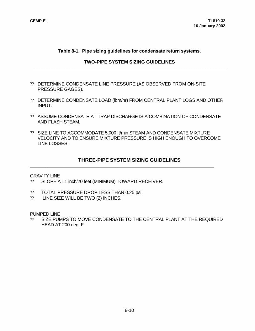
CEMP-E TI 810-32 10 January 2002
8-10
Table 8-1. Pipe sizing guidelines for condensate return systems.
TWO-PIPE SYSTEM SIZING GUIDELINES _____________________________________________________________________________
?? DETERMINE CONDENSATE LINE PRESSURE (AS OBSERVED FROM ON-SITE
PRESSURE GAGES). ?? DETERMINE CONDENSATE LOAD (lbm/hr) FROM CENTRAL PLANT LOGS AND OTHER
INPUT. ?? ASSUME CONDENSATE AT TRAP DISCHARGE IS A COMBINATION OF CONDENSATE
AND FLASH STEAM. ?? SIZE LINE TO ACCOMMODATE 5,000 ft/min STEAM AND CONDENSATE MIXTURE
VELOCITY AND TO ENSURE MIXTURE PRESSURE IS HIGH ENOUGH TO OVERCOME LINE LOSSES.
THREE-PIPE SYSTEM SIZING GUIDELINES ____________________________________________________________________________________ GRAVITY LINE ?? SLOPE AT 1 inch/20 feet (MINIMUM) TOWARD RECEIVER. ?? TOTAL PRESSURE DROP LESS THAN 0.25 psi. ?? LINE SIZE WILL BE TWO (2) INCHES. PUMPED LINE ?? SIZE PUMPS TO MOVE CONDENSATE TO THE CENTRAL PLANT AT THE REQUIRED
HEAD AT 200 deg. F.

CEMP-E TI 810-32 10 January 2002
A-1
APPENDIX A
REFERENCES Government Publications Department of the Army TM 5-802-1 Economic Studies for Military Construction Design-Applications TM 5-809-1 Load Assumption for Buildings Non-government Publications American National Standards Institute (ANSI) 1430 Broadway, New York, NY 10018 H35.1 (1990) Alloy and Temper Design System for Aluminum American Society for Testing and Materials (ASTM) 1916 Race Street, Philadelphia, PA 19103 A 36 (1991) Structural Steel A 53 (1988a) Pipe, Steel, Black and Hot Dipped, Zinc Coated, Welded and Seamless A 123 (1989a) Zinc (Hot-Dip Galvanized) Coatings on Iron and Steel Products A 615 (1990) Deformed and Plain Billet-Steel Bars for Concrete Reinforcement American Society of Heating, Refrigerating, and Air Conditioning Engineers, Inc.,
1791 Tullie Circle, N.E., Atlanta, GA 30329 ASHRAE Handbook Fundamentals ASHRAE Handbook HVAC Systems and Applications American Society of Mechanical Engineers (ASME),
22 Law Drive, Box 2300, Fairfield, NJ 07007-2300 B31.1 (1989) Power Piping Canadian Society of Civil Engineers,
Montreal, Quebec, Canada (1986) Cold Climate Utilities Manual

CEMP-E TI 810-32 10 January 2002
APPENDIX B
B-1
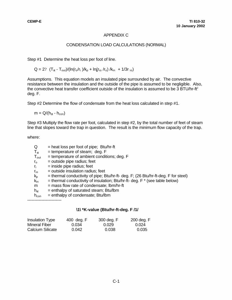
CEMP-E TI 810-32 10 January 2002
C-1
APPENDIX C
CONDENSATION LOAD CALCULATIONS (NORMAL) Step #1 Determine the heat loss per foot of line. Q = 2? (Tst - Tout)/(ln(ro/ri )/kp + ln(rio /ro) /kin + 1/3r io) Assumptions. This equation models an insulated pipe surrounded by air. The convective resistance between the insulation and the outside of the pipe is assumed to be negligible. Also, the convective heat transfer coefficient outside of the insulation is assumed to be 3 BTU/hr-ft2 deg. F. Step #2 Determine the flow of condensate from the heat loss calculated in step #1. m = Q/(hst - hcon) Step #3 Multiply the flow rate per foot, calculated in step #2, by the total number of feet of steam line that slopes toward the trap in question. The result is the minimum flow capacity of the trap. where: Q = heat loss per foot of pipe; Btu/hr-ft Tst = temperature of steam; deg. F Tout = temperature of ambient conditions; deg. F ro = outside pipe radius; feet ri = inside pipe radius; feet rio = outside insulation radius; feet kp = thermal conductivity of pipe; Btu/hr-ft- deg. F; (26 Btu/hr-ft-deg. F for steel) kin = thermal conductivity of insulation; Btu/hr-ft- deg. F * (see table below) m = mass flow rate of condensate; lbm/hr-ft hst = enthalpy of saturated steam; Btu/lbm hcon = enthalpy of condensate; Btu/lbm ------------------------
\1\ *K-value (Btu/hr-ft-deg. F /1/ Insulation Type 400 deg. F 300 deg. F 200 deg. F Mineral Fiber 0.034 0.029 0.024 Calcium Silicate 0.042 0.038 0.035
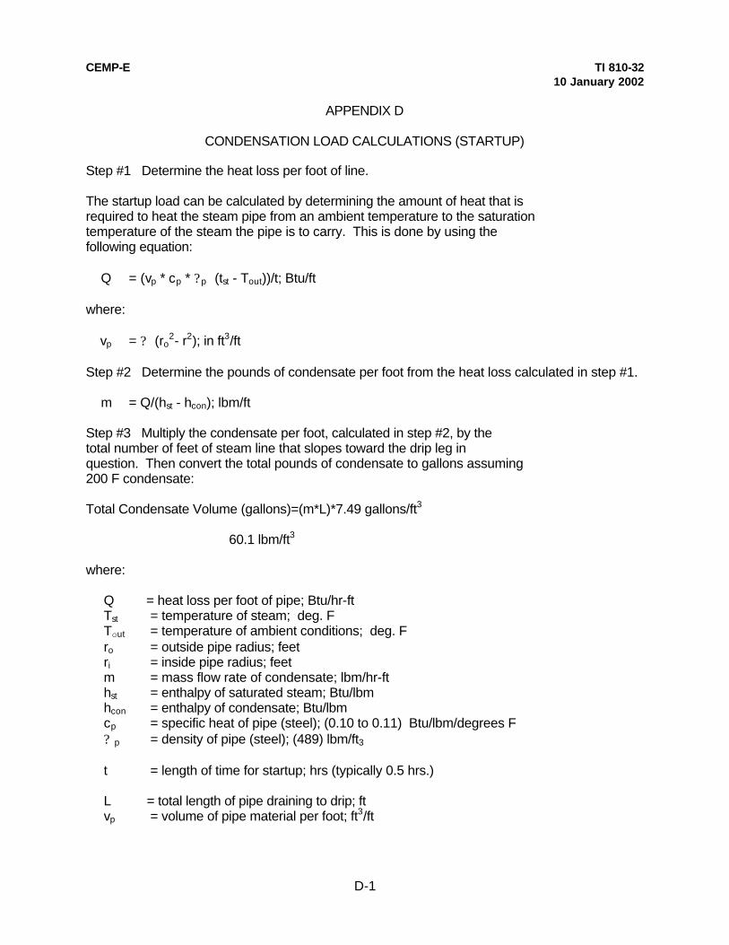
CEMP-E TI 810-32 10 January 2002
D-1
APPENDIX D
CONDENSATION LOAD CALCULATIONS (STARTUP) Step #1 Determine the heat loss per foot of line. The startup load can be calculated by determining the amount of heat that is required to heat the steam pipe from an ambient temperature to the saturation temperature of the steam the pipe is to carry. This is done by using the following equation: Q = (vp * cp * ?p (tst - Tout))/t; Btu/ft where: vp = ? (ro
2- r2); in ft3/ft Step #2 Determine the pounds of condensate per foot from the heat loss calculated in step #1. m = Q/(hst - hcon); lbm/ft Step #3 Multiply the condensate per foot, calculated in step #2, by the total number of feet of steam line that slopes toward the drip leg in question. Then convert the total pounds of condensate to gallons assuming 200 F condensate: Total Condensate Volume (gallons)=(m*L)*7.49 gallons/ft3 60.1 lbm/ft3 where: Q = heat loss per foot of pipe; Btu/hr-ft Tst = temperature of steam; deg. F Tout = temperature of ambient conditions; deg. F ro = outside pipe radius; feet ri = inside pipe radius; feet m = mass flow rate of condensate; lbm/hr-ft hst = enthalpy of saturated steam; Btu/lbm hcon = enthalpy of condensate; Btu/lbm cp = specific heat of pipe (steel); (0.10 to 0.11) Btu/lbm/degrees F ? p = density of pipe (steel); (489) lbm/ft3 t = length of time for startup; hrs (typically 0.5 hrs.) L = total length of pipe draining to drip; ft vp = volume of pipe material per foot; ft3/ft

TI 810-32 10 January 2002
Technical Instructions
HEATING AND COOLING DISTRIBUTION SYSTEMS
Headquarters U.S. Army Corps of Engineers Engineering Division Directorate of Military Programs
CEMP-E TI 810-32
10 January 2002
TECHNICAL INSTRUCTIONS
HEATING AND COOLING DISTRIBUTION SYSTEMS
Any copyrighted material included in this document is identified at its point of use. Use of the copyrighted material apart from this document must have the permission of the copyright holder.
Approved for public release; distribution is unlimited.
This document reissued 10 January 2002. Record of Changes (changes indicated \1\…/1/ ) No. Date Location 1 7 March 2002 Pages 4-1, 4-2, 5-1, and C-1 Table 4-2 Figures (editorial – changes not marked) 3-1 thru 3-28, 4-1, and 4-3 2 30 Sept 2002 Page 1-1 Figures (editorial – changes not marked) 3-14, 3-28, 4-4, 4-5, 4-17, and 7-7

CEMP-E TI 810-32 30 August 1999
Reissued 10 January 2002
FOREWORD
These technical instructions (TI) provide design and construction criteria and apply to all U.S. Army Corps of Engineers (USACE) commands having military construction responsibilities. TI will be used for all Army projects and for projects executed for other military services or work for other customers where appropriate. TI are living documents and will be periodically reviewed, updated, and made available to users as part of the HQUSACE responsibility for technical criteria and policy for new military construction. CEMP-ED is responsible for administration of the TI system; technical content of TI is the responsibility of the HQUSACE element of the discipline involved. Recommended changes to TI, with rationale for the changes, should be sent to HQUSACE, ATTN: CEMP-ED, 20 Massachusetts Ave., NW, Washington, DC 20314-1000. TI are effective upon issuance. TI are distributed only in electronic media through the TECHINFO Internet site http://www.hnd.usace.army.mil /techinfo/index.htm and the Construction Criteria Base (CCB) systems maintained by the National Institute of Building Sciences at Internet Site http://www.nibs.org/ccb/. Hard copies of these instructions produced by the user from the electronic media should be checked against the current electronic version prior to use to assure that the latest instructions are used. FOR THE COMMANDER:
DWIGHT A. BERANEK, P.E.
Chief, Engineering and Construction Division Directorate of Military Programs

CEMP-E TI 810-32 10 January 2002
i
HEATING AND COOLING DISTRIBUTION SYSTEMS
Table of Contents
Page CHAPTER 1. GENERAL INFORMATION
Paragraph 1-1. PURPOSE AND SCOPE.............................................................................. 1-1 1-2. APPLICABILITY............................................................................................... 1-1 1-3. REFERENCES............................................................................................... 1-1 1-4. EXCEPTIONS................................................................................................. 1-1 1-5. DEFINITIONS.................................................................................................. 1-1
CHAPTER 2. SYSTEM SELECTION
Paragraph 2-1. GENERAL .................................................................................................. 2-1 2-2. DISTRIBUTION MEDIA SELECTION ........................................................... 2-1
2-3. SYSTEM TYPES ......................................................................................... 2-1 2-4. SYSTEMS SELECTION ............................................................................... 2-2
CHAPTER 3. GENERAL DISTRIBUTION SYSTEM DESIGN
Paragraph 3-1. GENERAL .................................................................................................... 3-1 3-2. SITE SOIL SURVEY..................................................................................... 3-1 3-3. UTILITY INVESTIGATION ............................................................................. 3-1 3-4. SYSTEM LAYOUT PLAN/PROFILE ............................................................. 3-1 3-5. EXPANSION COMPENSATION ................................................................... 3-2 3-6. VALVE MANHOLES ...................................................................................... 3-3 ( Page 3-7 not used)
CHAPTER 4. HEAT DISTRIBUTION SYSTEMS IN CONCRETE TRENCHES
Paragraph 4-1. GENERAL .................................................................................................... 4-1 4-2. SYSTEM DESIGN ........................................................................................ 4-1 4-3. GENERAL CONSIDERATIONS ................................................................... 4-3
CHAPTER 5. PRE-ENGINEERED UNDERGROUND HEAT DISTRIBUTION SYSTEM
Paragraph 5-1. GENERAL..................................................................................................... 5-1 5-2. MANUFACTURER'S RESPONSIBILITY....................................................... 5-1 5-3. PROJECT DESIGNER'S RESPONSIBILITY............................................... 5-2
CHAPTER 6. PREFABRICATED UNDERGROUND HEATING/COOLING DISTRIBUTION SYSTEM Paragraph 6-1. GENERAL .................................................................................................... 6-1 6-2. SYSTEM DESIGN......................................................................................... 6-1 CHAPTER 7. ABOVEGROUND HEAT DISTRIBUTION SYSTEM Paragraph 7-1. GENERAL .................................................................................................... 7-1 7-2. SYSTEM DESIGN........................................................................................ 7-1

CEMP-E TI 810-32 10 January 2002
ii
CHAPTER 8. SPECIAL CONSIDERATIONS Paragraph 8-1. GENERAL .................................................................................................... 8-1 8-2. STEAM SYSTEMS....................................................................................... 8-1 8-3. HTHW SYSTEMS ........................................................................................ 8-3 8-4. LTHW and CW SYSTEMS .......................................................................... 8-3 APPENDIX A. REFERENCES ...................................................................................................A-1 APPENDIX B. PRESSURE DROP vs. FLOW CHART .............................................................B-1 APPENDIX C. CONDENSATION LOAD CALCULATIONS (NORMAL) .....................................C-1 APPENDIX D. CONDENSATION LOAD CALCULATIONS (STARTUP)....................................D-1
List of Figures Title Page
Figure 3-1. Typical valve manhole plan........................................................................... 3-8
3-2. Access Ladder detail..................................................................................... 3-9 3-3. Typical isolation flange detail....................................................................... 3-10 3-4. Typical valve/piping support detail............................................................... 3-11 3-5. Valve manhole elevation and section.......................................................... 3-12 3-6. Raised cover plate design .......................................................................... 3-13 3-7. Section A-A of raised cover plate ................................................................ 3-14 3-8. Section B-B of raised cover plate................................................................ 3-15 3-9. Section C-C of raised cover plate ............................................................... 3-16 3-10. Detail of raised cover plate......................................................................... 3-17 3-11. Lifting lug detail ........................................................................................... 3-18 3-12. Handle detail ............................................................................................... 3-19 3-13. Notes for raised cover plate ....................................................................... 3-20 3-14. Typical support cover plan (grate support) ............................................... 3-21 3-15. Detail of angle support for grating ............................................................. 3-22 3-16. Detail of structural support for grating....................................................... 3-23 3-17. Grating support steel locations.................................................................. 3-24 3-18. Detail of checker plate cover..................................................................... 3-25 3-19. Typical concrete cover plan ...................................................................... 3-26 3-20. Concrete cover details .............................................................................. 3-27 3-21. Gooseneck detail....................................................................................... 3-28 3-22. Valve manhole floor drain detail................................................................. 3-29 3-23. Remote sump basin.................................................................................. 3-30 3-24. Sump basin cover detail............................................................................ 3-31 3-25. Sump basin electrical details .................................................................... 3-32 3-26. Sump pump wiring diagram ...................................................................... 3-33 3-27. Valve manhole sump electrical details ...................................................... 3-34 3-28. Casing wall penetration detail.................................................................... 3-35 (Page 3-36 not used) 4-1. Free pipe support detail................................................................................. 4-4 4-2. Guided pipe support detail............................................................................. 4-5 4-3. Pipe anchor detail.......................................................................................... 4-6 4-4. Pipe support channel..................................................................................... 4-7 4-5. Trench dimension section............................................................................. 4-8
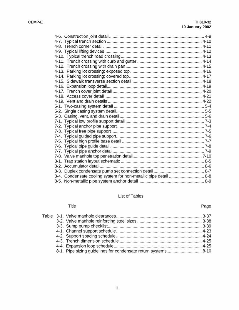
CEMP-E TI 810-32 10 January 2002
iii
4-6. Construction joint detail ................................................................................. 4-9 4-7. Typical trench section ................................................................................. 4-10 4-8. Trench corner detail .................................................................................... 4-11 4-9. Typical lifting devices................................................................................... 4-12 4-10. Typical trench road crossing..................................................................... 4-13 4-11. Trench crossing with curb and gutter ....................................................... 4-14 4-12. Trench crossing with drain pan................................................................. 4-15 4-13. Parking lot crossing; exposed top ............................................................. 4-16 4-14. Parking lot crossing; covered top.............................................................. 4-17 4-15. Sidewalk transverse section detail............................................................ 4-18 4-16. Expansion loop detail................................................................................. 4-19 4-17. Trench cover joint detail ............................................................................ 4-20 4-18. Access cover detail ................................................................................... 4-21 4-19. Vent and drain details ................................................................................ 4-22 5-1. Two-casing system detail ............................................................................. 5-4 5-2. Single casing system detail........................................................................... 5-5 5-3. Casing, vent, and drain detail ........................................................................ 5-6 7-1. Typical low profile support detail ................................................................... 7-3 7-2. Typical anchor pipe support .......................................................................... 7-4 7-3. Typical free pipe support ............................................................................... 7-5 7-4. Typical guided pipe support........................................................................... 7-6 7-5. Typical high profile base detail ...................................................................... 7-7 7-6. Typical pipe guide detail ................................................................................ 7-8 7-7. Typical pipe anchor detail.............................................................................. 7-9 7-8. Valve manhole top penetration detail........................................................... 7-10 8-1. Trap station layout schematic ....................................................................... 8-5 8-2. Accumulator detail......................................................................................... 8-6 8-3. Duplex condensate pump set connection detail ........................................... 8-7 8-4. Condensate cooling system for non-metallic pipe detail .............................. 8-8 8-5. Non-metallic pipe system anchor detail ........................................................ 8-9
List of Tables Title Page
Table 3-1. Valve manhole clearances......................................................................... 3-37 3-2. Valve manhole reinforcing steel sizes ....................................................... 3-38 3-3. Sump pump checklist................................................................................ 3-39 4-1. Channel support schedule......................................................................... 4-23 4-2. Support spacing schedule ......................................................................... 4-24 4-3. Trench dimension schedule ...................................................................... 4-25 4-4. Expansion loop schedule........................................................................... 4-25 8-1. Pipe sizing guidelines for condensate return systems.............................. 8-10

CEMP-E TI 810-32 10 January 2002
1-1
CHAPTER 1
GENERAL INFORMATION
1-1. PURPOSE AND SCOPE. This document provides criteria and guidance for the design and construction of heating and cooling distribution systems and supplements information in the "Notes to the Designer" of the guide specifications. These distribution systems include Heat Distribution Systems in Concrete Trenches, Pre-engineered Underground Heat Distribution Systems, Prefabricated Underground Heating/Cooling Distribution Systems, and Aboveground Heat Distribution Systems. The mediums used in these distribution systems, as defined by the Department of Defense (DoD), include: a. High temperature hot water (HTHW) (251 deg. F to 450 deg. F) b. Low temperature hot water (LTHW) (150 deg. F to 250 deg. F) c. Low pressure steam systems (up to 15 psig) d. High pressure steam systems (over 15 psig) e. Condensate return systems (up to 200 deg. F) f. Chilled water systems. 1-2. APPLICABILITY. These instructions are applicable to all \2\ DoD agencies /2/ and their contractors involved in the design and construction of heating and cooling distribution systems. 1-3. REFERENCES. Appendix A contains a list of references used in these instructions. 1-4. EXCEPTIONS. Generally, this document covers heating and cooling distribution systems most typically installed on United States military installations. However, deviations from the recommendations of this manual may be necessary when unusual site conditions are present or specific using service requirements are encountered. For example, the manual does not discuss design problems associated with arctic and subarctic construction, in which case, the designer should refer to the "Cold Climate Utilities Manual", 1986, Canadian Society of Civil Engineers, Montreal, Quebec. 1-5. DEFINITIONS. The term "designer" used throughout this manual refers to the person or persons responsible for preparing contract drawings and specifications for a heating or cooling distribution design. The main engineering discipline areas of the "designer" are: a. Mechanical. Includes expansion compensation, stress analysis, piping system design (fittings, valves, insulation), equipment selection and sizing, and pipe sizing and routing. b. Structural. Includes reinforced concrete design, pipe supports, and valve manhole cover design. c. Electrical. Includes cathodic protection, electrical service and controls (e.g. sump pumps). d. Civil. Includes earth work, road crossings (for buried systems), system plans and profiles, and area drainage designs.

CEMP-E TI 810-32 10 January 2002
2-1
CHAPTER 2
SYSTEM SELECTION 2-1. GENERAL. When designing a heating or cooling distribution system, the designer must first select two critical items: media type and system type. 2-2. DISTRIBUTED MEDIA SELECTION. a. Connecting to an existing system. Almost all heating and cooling distribution systems will be connected to an existing central distribution system. In this case, the designer most often designs for the media to which it is being connected-HTHW, LTHW, steam/condensate, or chilled water. b. Installation of new system. When no existing system is present, the designer must select the system that is most appropriate for the end user. High temperature hot water and steam/condensate systems are the most common types of distribution systems currently used on military installations. However, a new system should only use the temperatures and pressures necessary to meet the requirements of the installation. For example, the use of high pressure steam sterilizers or steam kettles at several facilities may require the use of a high pressure steam or HTHW system. However, it is usually much more cost effective (on a first cost and life cycle cost basis) to use a low or medium temperature hot water distribution systems whenever possible and to incorporate stand alone high pressure/temperature systems where required. The lower maintenance costs, safer operation, longer life of systems, and simpler system controls for hot water systems often offset the costs of larger piping required. For further assistance for selecting the system type, refer to ASHRAE Handbook, "HVAC Systems and Equipment.” 2-3. SYSTEM TYPES. When selecting a distribution system, the designer must determine which system types apply to a particular medium. The designer must also exclude systems which are not appropriate for a particular site or for which the customer has no interest. Examples of this are locating aboveground systems in non-industrial areas where the installation is sensitive to the aesthetic appearance of the area or routing concrete shallow trench systems through drainage swales or flood plains. a. Heat Distribution Systems in Concrete Trenches (chapter 4). This system is a buried system with its removable concrete cover installed at grade and will typically be used for HTHW and steam/condensate systems. In rare instances, it may also be used for chilled water and LTHW in the event no plastic piping is installed in the same trench as high temperature (greater than 250 degrees F) piping systems. Experience has shown that if insulation of a high temperature system is compromised, temperatures can increase to such a level and cause damage to the plastic piping. b. Pre-engineered Underground Heat Distribution Systems (chapter 5). This system is designed for higher pressure and temperature applications. The two types of pre-engineered systems are the drainable-dryable-testable (DDT) type which is used for high pressure steam/condensate and HTHW at all sites, and high temperature hot water at any type of site, and the water spread limiting (WSL) type which is used only for steam/condensate systems in bad and moderate sites. HTHW supply and return lines may be provided in a single casing; however, steam and condensate lines must always be provided in separate casings because condensate lines typically last less than half as long as the steam line and are easier to replace when in a separate casing. c. Prefabricated Underground Heating/Cooling Distribution System (chapter 6). This system is designed for lower temperature and pressure applications. It is typically used for LTHW, chilled water, or combination LTHW/chilled water systems. d. Aboveground Heat Distribution System (chapter 7). This system may be used for HTHW, steam/condensate, and LTHW systems, and for chilled water systems where freezing is not a concern.
CEMP-E TI 810-32 10 January 2002
2-2
2-4. SYSTEM SELECTION. The system type selected will be based on the type of media that is distributed. a. High Temperature Water and Steam/condensate Systems. The order of preference for system types for high temperature and high pressure systems are: (1) Aboveground Heat Distribution System. This is the least expensive system and historically requires the lowest maintenance and operating costs. However, the safety and aesthetics of an aboveground system are not always desirable and must be accepted by the end user. (2) Heat Distribution Systems in Concrete Trenches. This is the most dependable of the buried distribution systems. The piping is totally accessible through removable concrete covers, the piping does not come in contact with the soil, and ground water is drained away from the piping system to low point drains. Except in rare instances, this is the system that should be selected if aboveground is not acceptable with the end user.
(3) Pre-engineered Underground Heat Distribution System. This type of buried distribution system should be selected as the last option due to very short system lives which are typically caused by poor drainage, poor corrosion protection, and improper installation. Instances where it would be used would be when aboveground is not acceptable with the end user or when drainage swales and high ground water prevent the installation of a concrete trench system. b. Low Temperature and Chilled Water Systems. The order of preference for system types for hot water, chilled water or combination hot/chilled water are: (1) Aboveground Heat Distribution System. This is the least expensive system and historically requires the lowest maintenance and operating costs. However, the aesthetics of an aboveground system are not always desirable and must be accepted by the end user. In addition, aboveground systems are typically not used for chilled water because of potential freezing problems in colder climates and heat gain in warmer areas. (2) Prefabricated Underground Heating/Cooling Distribution System. This buried distribution system is relatively inexpensive and dependable. The non-metallic casing materials provide excellent protection from corrosion and the lower temperatures and pressures allow the system to operate for extended periods of time. It is an excellent application for chilled water since the system is installed underground, limiting the amount of heat gain to the system.

CEMP-E TI 810-32 10 January 2002
3-1
CHAPTER 3
GENERAL DISTRIBUTION SYSTEM DESIGN 3-1. GENERAL. Some aspects of a heating or cooling distribution system design are similar regardless of the system type. These aspects are covered in this chapter. 3-2. SITE SOIL SURVEY. After general routing has been proposed and before specific design has begun, a detailed soil survey will be conducted for all distribution systems. a. The survey will be made after the general layout of the system has been determined, will cover the entire length of the proposed system, and will be made by a geotechnical engineer. The geotechnical engineer will be a registered professional engineer with a minimum of three years of experience in the field of soil mechanics and foundation design. This engineer must also be familiar with the local soil conditions. b. If at all possible, the survey should be conducted during the time of the year when the ground-water table is at its highest point; if this is not possible, water table measurements will be corrected, on the basis of professional judgement and local knowledge, to indicate conditions likely to exist at the time of year when the water table is at its highest point. It may be necessary to dig test pits at the worst locations to investigate the soil for evidence of high water table. c. As a minimum, information on ground-water conditions, soil types, terrain, and precipitation rates and irrigation practices in the area of the system will be collected. This information will be obtained from available records at the installation. In addition, soil resistivity will be determined for the cathodic protection system design for Pre-Engineered Underground Heat Distribution Systems. d. Information on ground-water conditions and soil types (in most cases not necessary for Prefabricated Underground Heating and Cooling Distribution Systems and Aboveground Heat Distribution Systems) will be obtained through borings, test pits, or other suitable exploratory means. Generally, a boring test pit will be made at least every 100 feet along the line of the proposed system within areas of prior construction. In open undisturbed natural areas the spacing of borings may be increased. Each exploratory hole will extend to a level at least five feet below the anticipated elevation of the bottom of the proposed system. If a significant difference in underground conditions is found at adjacent exploratory points, additional explorations will be made between those points in order to determine more precisely where the change occurs. Upon completion of the survey, each exploration point will be classified on the basis of the criteria presented in the guide specification for Pre-Engineered Underground Heat Distribution Systems or in the guide specification for Heat Distribution Systems in Concrete Shallow Trenches. The classification criteria is different for each system. Note that although classification is not a requirement for design of Prefabricated Underground Heating and Cooling Distribution Systems or Aboveground Heat Distribution Systems, the site survey, except for borings or test pits, must be conducted to ensure that actual site characteristics have been identified so that accurate plan and profile drawings can be generated. 3-3. UTILITY INVESTIGATION. All existing, concurrently constructed and new utilities will be identified if within 25 feet of the proposed distribution system routing. If the proposed routing crosses any utilities, burial depths will be determined. Utility locations and depths can be verified through base personnel familiar with utilities, base/post utility maps and by site visits. The designer is responsible for these site visits to verify locations of utility interferences and to coordinate all other construction items with the user. In the event utility information is not available, utility location consultants may be procured who specialize in the location, identification and depth determination of utilities. If interferences exist, details will be provided in the design to relocate utilities or modify system routing to avoid the interference.

CEMP-E TI 810-32 10 January 2002
3-2
3-4. SYSTEM LAYOUT PLAN/PROFILE. All distribution systems require a layout plan and profile be provided by the designer. a. Layout plans will include, but not be limited to: (1) system routing (including expansion loops and bends, manhole locations and anchor locations). (2) stationing numbering for the system (one dimensional coordinates from the point of origin of the distribution system). (3) all utilities within 25 feet of the system. (4) all roads and buildings clearly labeled. (5) types of surface conditions (asphalt, concrete, seeding, gravel, etc.). (6) grade contour lines (new and existing). (7) all dimensions and clearances to ensure accurate routing. b. A profile of the system will also be drawn and, as a minimum, show: (1) all system stationing numbering. (2) system slope drawn to scale (1-inch to 20 feet minimum for all systems) to all low points. (3) new and existing grade. (4) all existing or new utilities shown at their actual burial depths. 3-5. EXPANSION COMPENSATION. All expansion systems, loops, and bends, will be sized in order to prevent excessive pipe stresses (due mainly from thermal expansion) from exceeding those allowed by the Power Piping Code, ASME B31.1. Mechanical expansion joints are not recommended for absorbing system expansion. Mechanical expansion joints greatly increase the maintenance requirements of the distribution systems. In the unlikely event that expansion joints must be used, they must be placed in an adequately sized valve manhole. The designer is responsible for expansion calculations for Heat Distribution Systems in Concrete Trenches, Prefabricated Underground Heating/Cooling Distribution Systems, and Aboveground Heat Distribution Systems. The designer is also responsible for the expansion and stress determinations in all the valve manholes, including the location of the equipment/pipe support locations. Even though the manufacturer is responsible for the expansion calculations for Pre-Engineered Underground Heat Distribution Systems, the calculations will be thoroughly reviewed by the designer at the shop drawing review. It is recommended that a three dimensional finite element computer program be used for determining system stresses. Many finite element software packages are available which operate on desktop computers. The temperature differential used in the stress analysis will be the maximum temperature of the media less the minimum temperature the system will encounter during a shutdown. All loops and bends will be sized based on zero percent cold springing. Cold springing effects lessen over time and are difficult to maintain in the event the system is ever cut, and shall therefore not be included in the analysis. However, loops may be installed with cold springing as an added conservative measure. 3-6. VALVE MANHOLES. For all distribution systems, valve manholes will be designed by the project designer. A valve manhole is required for all buried system lateral connections, all below
CEMP-E TI 810-32 10 January 2002
3-3
to above ground system transitions, all drain points (low points), all below ground valving, all trap stations, high points for vents of buried systems, and to minimize depth of buried systems. Distance between valve manholes varies with different applications. However, spacing shall never exceed 500 feet with Pre-Engineered Underground Heat Distribution Systems or Prefabricated Underground Heating/Cooling Distribution Systems to minimize excavation when searching for failures and to minimize effects of a failure. To enhance maintainability, avoid valve manholes deeper than 6 feet. a. Manhole internals. Layout of each manhole will be designed on a case by case basis. (1) Equipment/valve locations. It is important to first layout, to scale, all manhole piping, insulation, valving (with stems upright 90 degrees or less from vertical), and equipment and then locate the manhole walls around these appurtenances to ensure adequate manhole size and room for maintenance personnel. One line diagrams of piping and equipment are unacceptable. See figure 3-1 for a typical manhole plan. Note that all valve manhole layouts have certain designer requirements in common. The designer will: (a) Provide main line isolation valves in valve manholes to most efficiently minimize outages to buildings served by the distribution system. When installed, main line isolation valves will be located downstream of the building's service laterals. (b) Provide lateral isolation valves within the valve manholes for all laterals runs. (c) Locate all carrier pipe vents and drains needed within the manhole for proper system drainage of the main and lateral lines. (d) Layout all valve manhole internals (valves and valve stems, pipe w/insulation, access ladders, isolation flanges, and equipment) to scale to ensure adequate clearance has been provided for operation and maintenance within the manhole. (e) Ensure no non-metallic piping is routed in the manholes (i.e., as allowed with chilled water or condensate return systems) which also serves high temperature mediums that could damage the non-metallic piping. Damage to non-metallic piping is caused when manholes flood and the hot piping boils the flood water. Boiling water can exceed the temperature allowables of many nonmetallic piping materials. Because of this, the designer must transition to steel piping at the manholes (see figure 8-4). (2) Clearances. Design will provide for clearance around piping and equipment in the manhole in accordance with table 3-1. (3) Access Ladders. Access ladders will be required on all valve manholes greater than 3 feet in depth. Ladders will be welded steel and will consist of uprights and nonslip steps or rungs. Uprights will be not less than 16 inches apart and steps or rungs will be spaced no greater than 12 inches apart. Ladders will extend not less than 6 inches from the manhole wall and will be firmly anchored to the wall by steel inserts spaced not more than three 3 feet apart vertically. All parts of the ladders will be hot-dipped galvanized after fabrication in conformance with ASTM A 123. The top rung of the ladders shall be not more than 6 inches from the top of the manhole. A typical valve manhole access ladder detail is shown in figure 3-2. (4) Insulation. Insulation for valves, fittings, field casing closures, and other piping system accessories in valve manholes will be of the same types and thicknesses as those provided in the distribution systems' guide specification. All insulation will be premolded, precut, or job fabricated to fit and will be removable and reusable. Insulation jackets will be provided for all pipe insulation in manholes and will comply with the requirements of the particular distribution system guide specification.

CEMP-E TI 810-32 10 January 2002
3-4
(5) Isolation flanges. Isolation flanges will be provided when connecting to an existing cathodically protected heating or cooling distribution system or to prevent a new system's cathodic protection system from contacting an existing system. The isolation flanges will be installed in the valve manhole and a typical flange detail is shown in figure 3-3. (6) Valve/piping supports. Piping in valve manholes often will need supports within the manhole especially when larger valves or equipment are attached to the piping. These supports will be located on the manhole plans as determined by the designer's expansion compensation calculations for each manhole valving and equipment layout. Typical valve/piping support details are shown in figure 3-4. b. Valve manhole construction. Valve manholes will be field constructed of reinforced concrete conforming to the current criteria. Valve manholes will be constructed of 4,000 psi minimum compressive strength concrete. Reinforcing bars will conform to ASTM A 615, grade 60. Typical reinforcing steel details and sizing are shown in figure 3-5 and table 3-2 respectively. Concrete floor slabs and walls will be of sufficient weight to prevent flotation in high water table areas. Floor slabs will be sloped to the drain which will be installed in the floor slab. Concrete wall sections will be not less than 8 inches thick and must meet anticipated load and soil conditions. Side walls will be constructed in a monolithic pour. Water stops will be provided at all construction joints. Do not locate valve manholes in roads or parking areas which create an inadequate amount of manhole ventilation and poor access. c. Valve manhole covers. The valve manhole cover types discussed here are: raised solid plate, supported cover, and concrete. (1) Raised solid plate covers. Raised solid plate covers are preferred for HTHW and steam/condensate systems installed in Pre-Engineered Underground Heat Distribution Systems. For shallow concrete trench systems, the raised solid plate cover’s raised feature will interfere with the trench's walkway function. When the valve manhole cover must remain flush with the trench top, the supported cover is the preferred type. For the raised solid plate cover, ventilation openings are provided around the entire perimeter below the raised top. The height of the valve manhole wall above grade (6 inches, minimum) shall be sufficient to prevent surface water entry. The solid plate cover assembly is removable. The cover, constructed of aluminum, also provides sectionalized access for inspection and maintenance. The solid plate cover raised frame design and section, lifting lug, and handle details are shown in figure 3-6 through 3-12. Figure 3-13 contains notes for raised solid plate cover figures. (2) Supported covers. Supported covers may be used for any distribution system covered in this manual. For Pre-engineered Underground or Prefabricated Underground Heat Distribution Systems, design the cover to be at least 6 inches above the surrounding grade. When used for concrete shallow trench systems, the finished top will be flush with the concrete trench top. Required grates or other structural members used for supporting covers to be made of corrosion resistant material such as aluminum or galvanized steel. Details for the supporting cover are shown in figures 3-14 through 3-18. These details are designed for loadings up to 150 psf and must be re-evaluated for larger loadings. Other structural solutions for supporting the checkered plate are acceptable. The checkered plate cover (also referred to as diamond or embossed plate) as shown in figure 3-18, will be installed over grating or other structural supports in most locations to minimize the influx of leaves and other debris. The checkered plate is attached to the grating and is removable. (3) Concrete covers. The use of concrete covers is discouraged, but, if used, they must be used with 4 x 4 ft. aluminum doors for any distribution system covered in this manual. Concrete covers should only be used if desired by the user or if specific design conditions exist, such as below to aboveground system transitions. When used for Pre-engineered Underground or Prefabricated Underground Heat Distribution Systems, design the top of the concrete cover to be a minimum of 6 inches above the surrounding grade. When used for concrete shallow trenches, design the cover to be flush with the trench top. Concrete requirements for this cover are similar to those required for valve manhole construction. Concrete cover will be designed to support anticipated loadings. Figure 3-19 shows a typical concrete cover plan and figure 3-20

CEMP-E TI 810-32 10 January 2002
3-5
provides construction details for this cover. The concrete cover detailed is designed for loadings up to 150 psf. For greater loadings, the design must be re-evaluated. A disadvantage of concrete covers is the difficulty in providing ventilation. For concrete shallow trench systems, a single 6 inch gooseneck pipe will be used, as detailed in figure 3-21, to allow steam to exit the valve manhole if a leak or excessive heat loss is present. Note that for shallow trench systems, the gooseneck will be installed off to one side of the valve manhole concrete top to minimize pedestrian traffic interference. For Pre-engineered Underground Heat Distribution Systems, two 6 inch goosenecks will be used. One will extend below the top as detailed in figure 3-21. The other will be similar but will extend to within 8 inches of the valve manhole floor on the opposite side of the manhole. d. Valve manhole drainage. Drainage of water from the valve manhole is mandatory for the successful operation and longevity of buried heating or cooling distribution systems. There are three types of valve manhole drainage systems described in this manual: gravity drainage, pumped drainage from a sump basin, and pumped drainage from the valve manhole. (1) Gravity drainage. The most cost effective and lowest maintenance system is gravity drainage to a storm drain when location, depth of existing storm drains, and local regulatory requirements allow this possibility. Drainage lines will be 6 inches in diameter minimum and will conform to the latest storm drain criteria and will be sloped at one percent, minimum. Valve manhole outlet will be a floor drain with backflow preventer to prevent storm water inflow from the storm drain (see figure 3-22). Note that valve manhole drain outlets shall be covered with a "hat type" cast iron pipe screen to minimize the accumulation of trash over the drain inlet. Also, the manhole floor will be sloped toward the drain. (2) Pumped drainage from sump basin. For pumped drainage, a duplex submersible pump system installed in a remote sump basin may be provided as indicated in figures 3-23 and 3-24. The sump basin will be located no more than 10 feet from the valve manhole. Drainage from the valve manhole to the sump basin will be similar to drainage to a storm drain including the valve manhole floor drain (fig 3-22). Discharge from the pumps can be routed to a splashblock at grade or to an adjacent storm sewer. Design of the surrounding grade must ensure drainage away from the sump basin, valve manhole and concrete shallow trench (if used) when discharging to grade. A power pedestal complete with failure warning light will be provided with each basin as shown in figure 3-25. A typical wiring diagram and sequence of operation are shown in figure 3-26. A specification for the sump basin system can be included in the applicable manhole or heat distribution section of the contract specification. The sump basin design has proven to operate well even in the colder climates of the upper tier states in the continental United States. It is also an excellent method to retrofit existing manholes that currently do not drain properly. The remote sump basin increases the life of the systems by removing the sump pump and pump controls from the hot, humid environment of the manhole. Also, pump maintenance will be done outside of the manhole. The pumps are easily disconnected and lifted to grade. The sump pumps used in the sump basin must incorporate the design characteristics listed in table 3-3. (3) Pumped drainage from valve manhole. Another means to pump water from the manhole is to locate the duplex sump pumps in the valve manhole. Typically, a 2'0" by 2'0" by 1'0" (deep) sump will be provided in a corner of the valve manhole. The duplex sump pumps will be installed to pump out of this sump. Valve manhole sump pump electrical arrangement should be installed as shown in figure 3-27. The control panel with high level warning light will be mounted adjacent to the valve manhole at grade. This keeps the electrical panel out of the hot, humid environment of the manhole. The sequence of operation and wiring diagrams will meet the requirements of figure 3-26. Pump discharge can be routed to a splashblock at grade (similar to the sump basin discharge piping arrangement on figure 3-23) or to an adjacent storm drain. Electric sump pumps used in the valve manholes must incorporate the design characteristics listed in table 3-3. Note that life of the pumps are typically shortened when installed in the hot and humid valve manhole environment. e. General. (1) Valve manhole wall penetrations. A design must be provided for the distribution system wall
CEMP-E TI 810-32 10 January 2002
3-6
penetrations. For a shallow trench system, the wall penetrations will typically be the same size as the inside dimension of the shallow trench connecting to the valve manhole. For shallow trench dimensions, refer to chapter 4 of this manual. Structural reinforcement must be designed around this opening. Drainage from the trench will then flow into the manhole. For Pre-engineered or Prefabricated Underground Heat Distribution Systems, sleeved openings will typically be provided with an expandable seal between the casing and the pipe sleeve as indicated on figure 3-28. Structural reinforcement must be designed to avoid contact with the pipe sleeve and water stop to prevent grounding of the system's cathodic protection. (2) Waterproofing. Waterproof membranes will be placed in or below the concrete bottom slab and continued up the outer sides to the top of the sidewalls in accordance with the valve manhole guide specification. (3) Pipe anchoring adjacent to valve manholes. Regardless of the buried distribution system, pipe anchors should be provided between 2 to 5 feet of a manhole wall to minimize movement through the manhole. For piping which passes through valve manholes, anchoring on one side only is typically adequate. Anchoring piping on more than one side may restrict piping movement and overstress the piping in the valve manhole. Anchors will typically be provided as part of the distribution system and will not be embedded in the manhole wall. However, if the manhole is used to support an anchor, the manhole must be designed to withstand the forces exerted by the system. Expansion compensation stress calculation will always be conducted to ensure proper anchor locations throughout the distribution system. These calculations must also account for the expansion in the valve manholes. (4) Piping materials in valve manholes. Nonmetallic piping must not be used in the same valve manholes as piping carrying higher temperature media that could cause the temperature around the non-metallic piping to exceed the allowables and potentially cause permanent damage to the non-metallic piping. In addition, chilled water systems with PVC carrier piping must never be installed in the same valve manhole with any heating system.

CEMP-E TI 810-32 10 January 2002
3-8
Figure 3-1. Typical Valve Manhole Plan.
12" 0 1' 2' 4'3'
12SCALE.
. INCH= 1 FOOT
PLAN
10" STEAM
STORM WATEROUTLET
LADDER
1 1/2 " CONDENSATE
3" STEAM
10" 300#GATE VALVE
4" 150#GATE VALVE
3" 300#GATE VALVE
1 1/2 " 150#GATE VALVE
4" CONDENSATE10" STEAM
10'-0
" *
13'-6" *
VALVE MANHOLE
VALVE AND PIPESUPPORT (TYP. OF 2)(SEE FIG. 3-4)
RUNGS
*NOTE TO THE DESIGNER:
DIMENSIONS OF VALVE MANHOLES DETERMINED ON A CASE BY CASE BASIS
NOTE: Drip leg trap station is not shown on the plan view.

CEMP-E TI 810-32 10 January 2002
3-9
Figure 3-2. Access Ladder Detail.
012" 6" 1'SCALE.
. INCH= 1 FOOT1
16" 7"
6"
12
"
8"
3'-0
" M
AX
.
2"
VA
LV
E M
AN
HO
LE
DE
PT
H V
AR
IES
3"
3/4 " DIA. RUNG(TYP.)
9" X 4" X 2"WIDE X 1/2 "THICK STEELBRACKET(TYP.)
BOTTOM OFVALVEVAULT
1/2 " DIA. EXPANSIONANCHOR BOLTS(TYP.)
NEW OREXISTINGWALL
2" X 3/8 " STEELBAR (TYP.)
TOP OF PIT
ACCESS LADDER
TYP. 1/4

CEMP-E TI 810-32 10 January 2002
3-10
Figure 3-3. Typical Isolation Flange Detail.
FLANGE BOLT
STEEL WASHER
INSULATING BOLT SLEEVE1/16" MIN. WALL THICKNESS
NUT
STEEL WASHER FLANGES
PIPE
NO SCALE
ISOLATION FLANGENOTE:
CONTRACTOR SHALL COMPLY WITH THE ISOLATION FLANGE MANUFACTURER'SRECOMMENDATIONS FOR BOLT TORQUES AND BOLTING PATTERN. CONTRACTORSHALL ALSO RECHECK BOLT TORQUES 72 HOURS AFTER SYSTEM STARTUP.
1/8 " THK. INSULATING GASKETSET SIMILAR
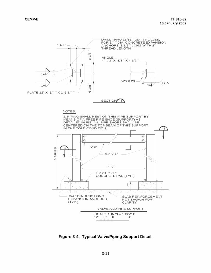
CEMP-E TI 810-32 10 January 2002
3-11
Figure 3-4. Typical Valve/Piping Support Detail.
W6 X 20
PLATE 12" X 3/4 " X 1'-3 1/4 "
1/4
1/4
3
3
1SECTION
1
1
1. PIPING SHALL REST ON THIS PIPE SUPPORT BYMEANS OF A FREE PIPE SHOE (SUPPORT) AS DETAILED IN FIG. 4-1. PIPE SHOES SHALL BECENTERED ON THE TOP BEAM OF THIS SUPPORTIN THE COLD CONDITION.
NOTES:
SLAB REINFORCEMENTNOT SHOWN FORCLARITY
4'-0"
VA
RIE
S
W6 X 20
1/4 TYP.
ANGLE 4" X 3" X 3/8 " X 4 1/2 "
012" 6" 1'SCALE.. INCH= 1 FOOT1
6 1
/8 "
6 1
/8 "
4 1/4 "
18" x 18" x 6"CONCRETE PAD (TYP.)
6"
3/4 " DIA. X 10" LONGEXPANSION ANCHORS(TYP.)
VALVE AND PIPE SUPPORT
5/8 " J
DRILL THRU 13/16 " DIA. 4 PLACES,FOR 3/4 " DIA. CONCRETE EXPANSIONANCHORS, 8 1/2 " LONG WITH 2"THREAD LENGTH

CEMP-E TI 810-32 10 January 2002
3-12
Figure 3-5. Valve Manhole Elevation and Section.
3" COVER(TYP)6"(TYP)
2" COVER6"(TYP)
W.S.(TYP)
2" COVER(TYP)
VERT. BARS
HORIZ. BARS
4" CLEAR(TYP)
BOTTOM PRINCIPAL REINFORCEMENT
BOTTOM SECONDARY REINFORCEMENT
TOP PRINCIPALREINFORCEMENT
TOP SECONDARYREINFORCEMENT
#5@EA. VERTICAL BAR,EMBED 24"(MIN.)IN WALL
(GRATE COVER SHOWN, FOR CONCRETE COVER SEE DETAIL A ON C-24)
L2
H1
NO SCALE
NOTESEE TABLE 3-2FOR REINFORCEMENTBAR SIZES.
* *
NO SCALE
L1
W1
L2
W2
HORIZ. BARSVERT. BARS
2'-4
"1
'
W.S.(TYP)
PLAN IN SECTION
8" (typ.)
VALVE MANHOLE SECTION
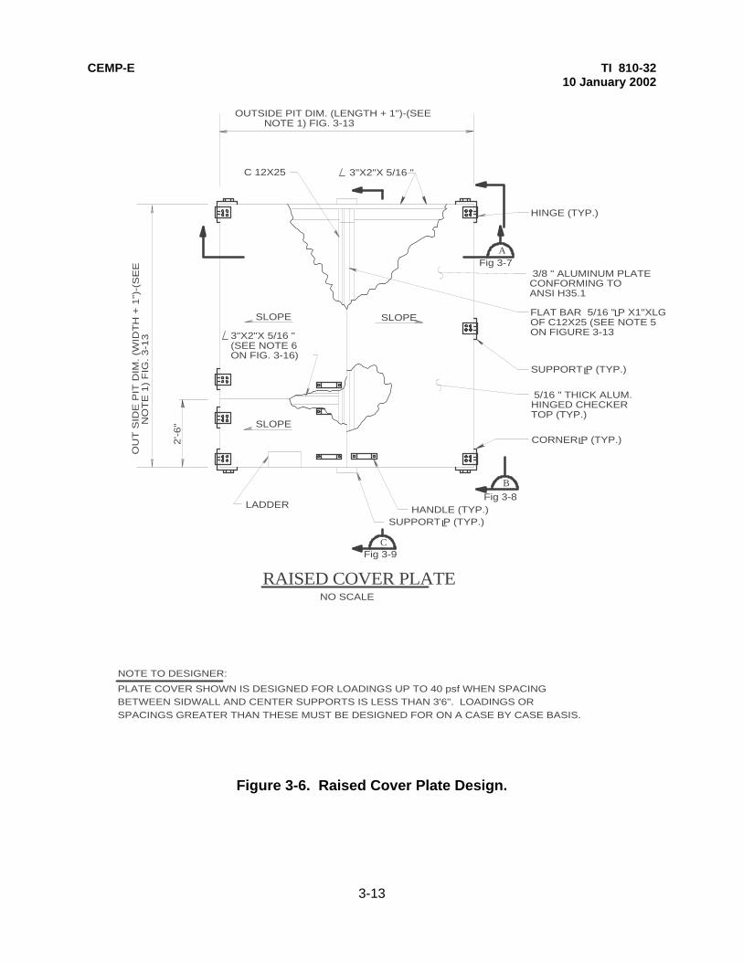
CEMP-E TI 810-32 10 January 2002
3-13
Figure 3-6. Raised Cover Plate Design.
3/8 " ALUMINUM PLATECONFORMING TOANSI H35.1
FLAT BAR 5/16 " P X1"XLGOF C12X25 (SEE NOTE 5ON FIGURE 3-13
L
SUPPORT P (TYP.)L
5/16 " THICK ALUM.HINGED CHECKERTOP (TYP.)
CORNER P (TYP.)L
HANDLE (TYP.)SUPPORT P (TYP.)L
LADDER
2'-6
"
OU
T S
IDE
PIT
DIM
. (W
IDT
H +
1")
-(S
EE
N
OT
E 1
) F
IG.
3-1
3
OUTSIDE PIT DIM. (LENGTH + 1")-(SEE NOTE 1) FIG. 3-13
HINGE (TYP.)
C 12X25 3"X2"X 5/16 "
3"X2"X 5/16 "(SEE NOTE 6ON FIG. 3-16)
SLOPE
SLOPE SLOPE
NO SCALE
RAISED COVER PLATE
B
A
C
NOTE TO DESIGNER:
PLATE COVER SHOWN IS DESIGNED FOR LOADINGS UP TO 40 psf WHEN SPACINGBETWEEN SIDWALL AND CENTER SUPPORTS IS LESS THAN 3'6". LOADINGS ORSPACINGS GREATER THAN THESE MUST BE DESIGNED FOR ON A CASE BY CASE BASIS.
Fig 3-9
Fig 3-8
Fig 3-7

CEMP-E TI 810-32 10 January 2002
3-14
Figure 3-7. Section A-A of Raised Cover Plate.
NO SCALE
SECTION A-A
CONC. PIT WALL(TYP.)
DETAIL - 1(FIG. 3-10)
GRADE
6"

CEMP-E TI 810-32 10 January 2002
3-15
Figure 3-8. Section B-B of Raised Cover Plate.
NO SCALE
SECTION B-B
OUTSIDE CONCRETE VALVEMANHOLE WALL (TYP.)
LIFTING LUG DETAIL (TYP.)(SEE FIGURE 3-11)
1'-4"X6"X 5/16 " SUPPORTPLATE (SEE NOTE 2 ONFIGURE 3-13)
TYP. 5/16
2 1/4 TYP.4 PLACESPER PLATE TYP.
2 1/4
ANGLE FRAME
1'-4"X6"X 5/16 " CORNER PLATE(8 REQ'D PER ASSEMBLY)
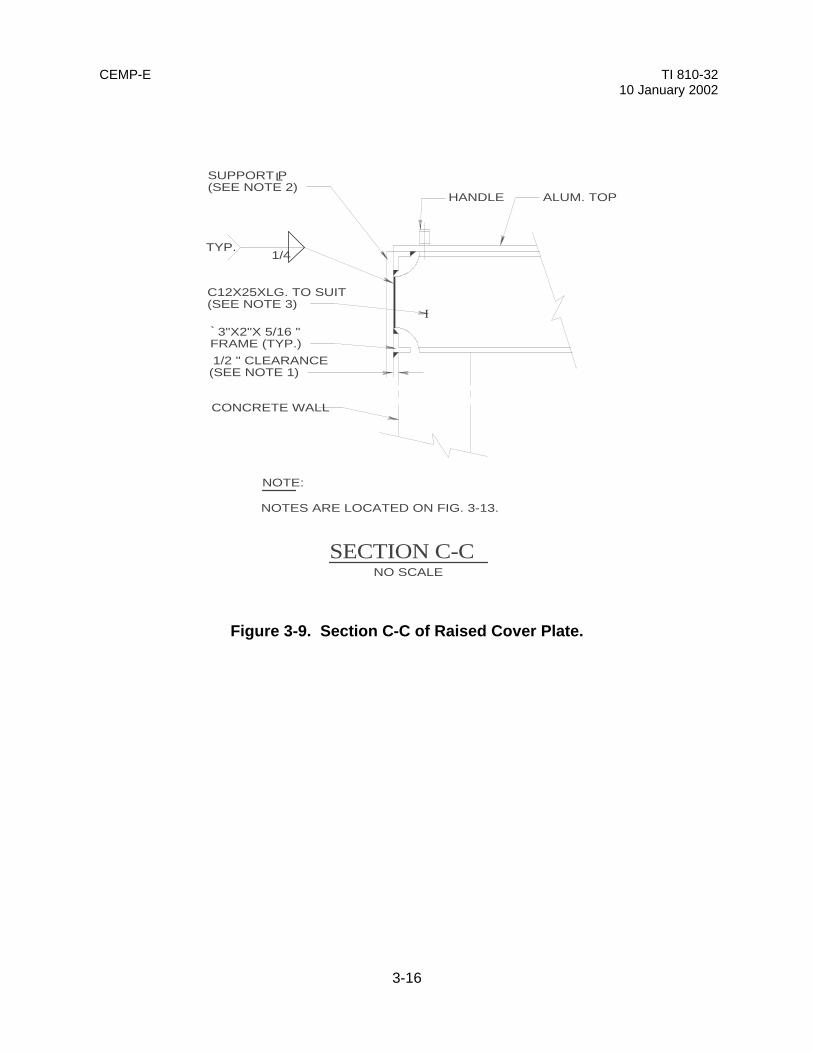
CEMP-E TI 810-32 10 January 2002
3-16
Figure 3-9. Section C-C of Raised Cover Plate.
ALUM. TOPHANDLE
SUPPORT P(SEE NOTE 2)
L
C12X25XLG. TO SUIT(SEE NOTE 3)
3"X2"X 5/16 "FRAME (TYP.)
I`
1/2 " CLEARANCE(SEE NOTE 1)
CONCRETE WALL
NO SCALE
NOTES ARE LOCATED ON FIG. 3-13.
NOTE:
SECTION C-C
TYP. 1/4

CEMP-E TI 810-32 10 January 2002
3-17
Figure 3-10. Detail of Raised Cover Plate.
1/4
6
NO SCALE
NO. 2 MESH HARDWARECLOTH, TACK WELD TO3"X2"X 5/16 " ANGLE FRAME
3" S.S. HINGE, WELD TO CORNERP 8, BOLT TO ALUM. TOP WITHS.S. BOLTS, HEX NUTS AND WASHERS TO SUIT.
CORNER PL
L
TYP.
1/4 TYP.
1/4 TYP.
DETAIL - 1

CEMP-E TI 810-32 10 January 2002
3-18
Figure 3-11. Lifting Lug Detail.
2"
4"
13/4 "
6"
1 1/2 "
R0 3/4 "
3/8 " THK. P L
NOTE: 4 LUGS REQ'D PER ASSEMBLY
NO SCALE
LIFTING LUG
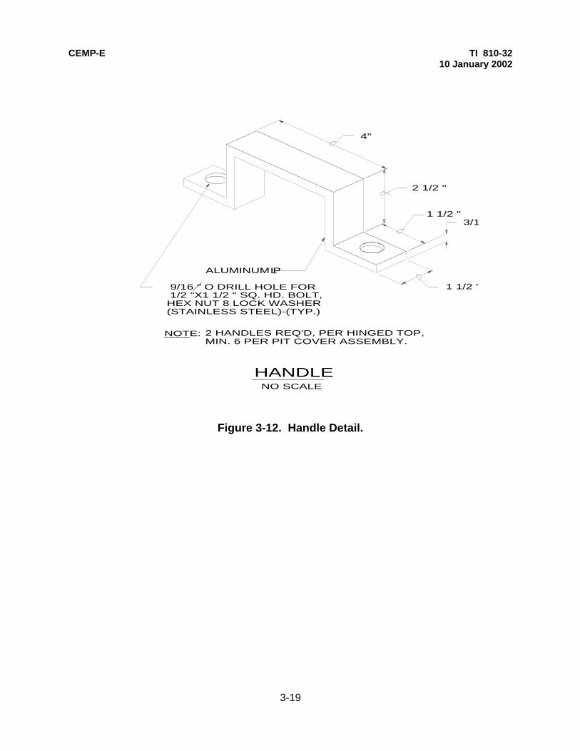
CEMP-E TI 810-32 10 January 2002
3-19
Figure 3-12. Handle Detail.
4"
2 1/2 "
1 1/2 " 3/16 "
1 1/2 "
ALUMINUM P
9/16 " O DRILL HOLE FOR 1/2 "X1 1/2 " SQ. HD. BOLT,HEX NUT 8 LOCK WASHER(STAINLESS STEEL)-(TYP.)
HANDLENO SCALE
NOTE: 2 HANDLES REQ'D, PER HINGED TOP,MIN. 6 PER PIT COVER ASSEMBLY.
L

CEMP-E TI 810-32 10 January 2002
3-20
Figure 3-13. Notes for Raised Cover Plates.
GENERAL NOTES: (FOR RAISED COVER PLATE)
EACH SUPPORT PLATE SHALL BE LOCATED HALFWAY BETWEEN CORNERPLATES AT 3 SIDES OF MANHOLE. 2 SUPPORT PLATES SHALL BE LOCATEDBETWEEN 2 SPLIT ALUM. CHECKER TOP AT ONE SIDE OF MANHOLE.
CHANNEL SUPPORT, CORNER PLATES, SUPPORT PLATES, ANGLE FRAMEHARDWARE CLOTH, AND LIFTING LUGS SHALL BE HOT-DIPPED GALVANIZEDBEFORE INSTALLATION ON VALVE MANHOLES.
FLAT BAR 5/16 " THK. WELDED TO TOP OF C12X25 TO MAKE ALUM.CHECKER TOP SLIGHTLY SLOPED AS INDICATED. LOCATE FLAT BARTO MATCH CHANNEL BEFORE WELDING.
ANGLE 3"X2"X 5/16 " WELDED TO C12X25 8 3"X 2"X5/16" AT EACH ENDLENGTH SHALL EQUAL HALF OF LENGTH OR WIDTH OF VALVE MANHOLE.
1.
2.
3.
4.
5.
6.
FIELD VERIFY OUTSIDE DIMENSIONS OF NEW MANHOLE BEFORE CONSTRUCTINGMANHOLE COVER ASSEMBLY. ADD 1" TO OUTSIDE MANHOLE DIMENSIONS(TO ALLOW FOR CLEARANCE) TO DETERMINE INSIDE ASSEMBLY DIMENSIONS.
SUPPORT CHANNELS SHALL BE C12X25XLG, TO EQUAL WIDTH OR LENGTHDIM. PLUS 1" TO SUIT INSIDE ASSEMBLY DIM. THE CHANNEL SHALL RESTON THE CONCRETE MANHOLE TOP AND THE ALUM. TOP SHALL REST ON THEFLAT BAR PLATE.

CEMP-E TI 810-32 10 January 2002
3-21
Figure 3-14. Typical Supported Cover Plan (Grate Support).
GRATINGGRATING
VALVE MANHOLECL
1/8 "
1/8 "
1/8 "
1/8 " 1/8 "
TO
SU
IT M
AN
HO
LE2'
-6"
MIN
.
1/2 LENGTH OF PIT
1/4 " SPACE
NO SCALE
NOTE TO DESIGNER:
GRATES IN FIGURES 3-14 THRU 3-16 ARE FOR LOADINGS UP TO 150 psf.LOADINGS GREATER THAN THESE MUST BE DESIGNED FOR ON A CASE BY CASE BASIS.
SEE DETAILFIGURE 3-15
SEE DETAILFIGURE 3-16
TYPICAL SUPPORTED COVER PLAN(GRATE SUPPORT)
THIS SECTION OFGRATING TO BEINSTALLED OVER MANHOLE ACCESSLADDER

CEMP-E TI 810-32 10 January 2002
3-22
Figure 3-15. Detail of Angle Support for Grating.
EXIST. FIN.GRADE 1/8 "
ANGLE SUPPORT FOR GRATING
5/8 "X 5/16 " BAR ALLAROUND WELD TOANGLE
6"MIN.
`1 3/4 x 1 3/4 x 1/4
1/2 " x 4" LOADED ANCHORSTUD @ 2'-6" O.C.
GRATING SHALL BE GALVANIZED AND CONFORM TO FEDERALSPECIFICATION RR-G-661. GRATING OVER MANHOLE,EXCEPT LADDER ACCESS PORTION, TO BE W-19-4 (1x 3/16)GRATING, CAPABLE OF A UNIFORM LOADING OF 145 psf
NO SCALE

CEMP-E TI 810-32 10 January 2002
3-23
Figure 3-16. Detail of Structural Support for Grating.
8"
L
1/8 "
1/2 WIDTH OFPIT WALL
1/2 " ANCHOR BOLTSW/LOCK WASHER &NUT (2 REQ'D)
1/2 " ANCHOR BOLTSW/LOCK WASHER &NUT (2 REQ'D)
EXIST. FIN.GRADE
STRUCTURAL SUPPORT FOR GRATINGNO SCALE
GRATING, SEE DETAILFIGURE 3-17
W 10X26 BEAM LOCATEDAT C OF VALVE PIT,SEE FIGURE 3-19 FORLOCATION REQUIREMENTS
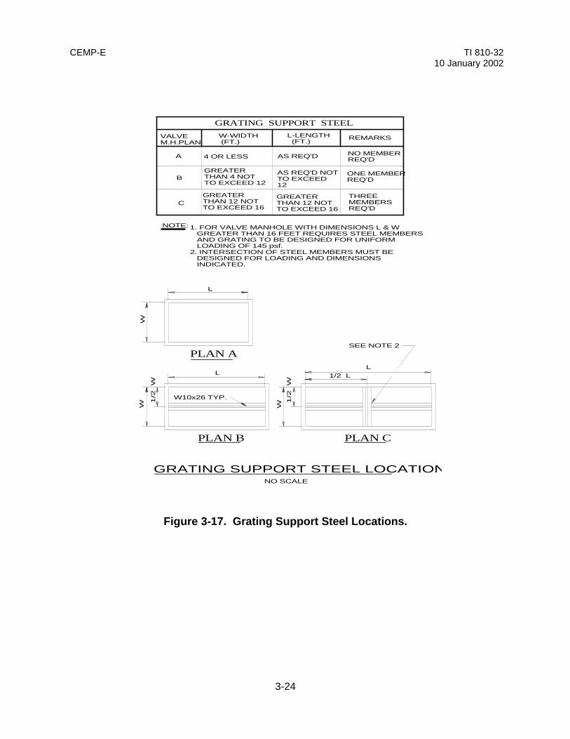
CEMP-E TI 810-32 10 January 2002
3-24
Figure 3-17. Grating Support Steel Locations.
GREATERTHAN 12 NOTTO EXCEED 16
GREATERTHAN 12 NOTTO EXCEED 16
THREEMEMBERSREQ'D
ONE MEMBERREQ'D
AS REQ'D NOTTO EXCEED12
GREATERTHAN 4 NOTTO EXCEED 12
C
B
A
W-WIDTH (FT.)
L-LENGTH (FT.)
REMARKS
GRATING SUPPORT STEEL
4 OR LESS AS REQ'D NO MEMBERREQ'D
WW W 1
/2
W
1/2
W
LL
L
1/2 L
VALVEM.H.PLAN
PLAN A
PLAN B PLAN C
NOTE:
GRATING SUPPORT STEEL LOCATIONSNO SCALE
1. FOR VALVE MANHOLE WITH DIMENSIONS L & W GREATER THAN 16 FEET REQUIRES STEEL MEMBERS AND GRATING TO BE DESIGNED FOR UNIFORM LOADING OF 145 psf.2. INTERSECTION OF STEEL MEMBERS MUST BE DESIGNED FOR LOADING AND DIMENSIONS INDICATED.
SEE NOTE 2
W10x26 TYP.
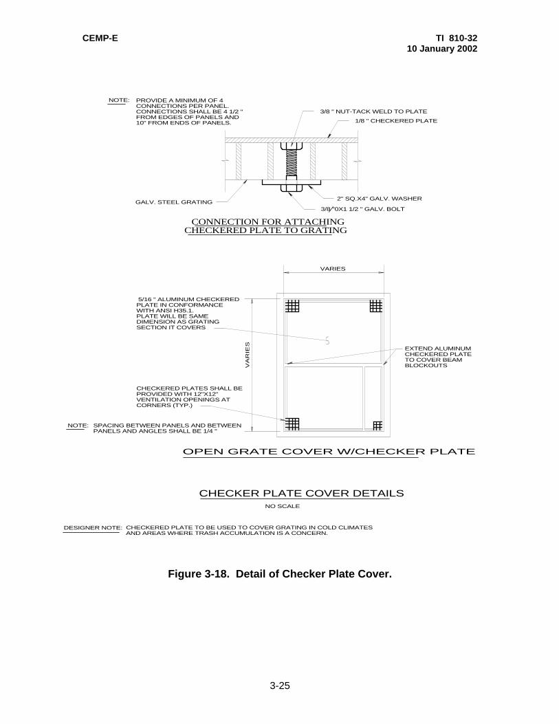
CEMP-E TI 810-32 10 January 2002
3-25
Figure 3-18. Detail of Checker Plate Cover.
VARIES
VA
RIE
S
5/16 " ALUMINUM CHECKEREDPLATE IN CONFORMANCEWITH ANSI H35.1.PLATE WILL BE SAMEDIMENSION AS GRATINGSECTION IT COVERS
SPACING BETWEEN PANELS AND BETWEENPANELS AND ANGLES SHALL BE 1/4 "
NOTE:
CHECKERED PLATES SHALL BEPROVIDED WITH 12"X12"VENTILATION OPENINGS ATCORNERS (TYP.)
NO SCALE
OPEN GRATE COVER W/CHECKER PLATE
GALV. STEEL GRATING2" SQ.X4" GALV. WASHER
1/8 " CHECKERED PLATE
3/8 " NUT-TACK WELD TO PLATE
NOTE:
3/8 "0X1 1/2 " GALV. BOLT
PROVIDE A MINIMUM OF 4CONNECTIONS PER PANEL.CONNECTIONS SHALL BE 4 1/2 "FROM EDGES OF PANELS AND10" FROM ENDS OF PANELS.
CONNECTION FOR ATTACHINGCHECKERED PLATE TO GRATING
CHECKERED PLATE TO BE USED TO COVER GRATING IN COLD CLIMATESAND AREAS WHERE TRASH ACCUMULATION IS A CONCERN.
DESIGNER NOTE:
EXTEND ALUMINUMCHECKERED PLATETO COVER BEAMBLOCKOUTS
CHECKER PLATE COVER DETAILS

CEMP-E TI 810-32 10 January 2002
3-26
Figure 3-19. Typical Concrete Cover Plan.
D (MANHOLE COVER)
G H4'(ACC. DOOR)
1'-2 1/2 " 1'-2 1/2 "B (MANHOLE WALLS- INSIDE FACE)
A(MANHOLEWALLS-
INSIDEFACE)
E
4'(ACC.DOOR)
FC(MANHOLECOVER)
1'-2 1/2 "
#4@ 9"O.C. EACHWAY,TYP.
6" GOOSENECK
CONCRETE SHALLOWTRENCH,(IF USED)
4'-0"X4'-0" ALUMINUM ACCESSDOOR,"BILCO" MODEL JD-2ALOR EQUAL W/SLIP RESISTANTFINISHLADDER
HINGES(TYP.)
TWOADDITIONAL #5EACH SIDE OFOPENING
NO SCALE
1
1
*
* SEE FIGURE 3-20FOR SECTION
(11'-0" max.)
NOTE TO DESIGNER:
CONCRETE COVER DETAILED IS DESIGNED FOR LOADINGS UP TO 150 psf.LOADINGS GREATER THAN THESE MUST BE DESIGNED FOR ON A CASE BY CASE BASIS.
CONCRETE COVER PLAN
SECOND 6" GOOSENECK FORDIRECT BUIRIED SYSTEMS ONLY
IF CONCRETE TRENCH USED, THISPORTION OF CONCRETE MANHOLE LID'SLIP TO BE DELETED TO ALLOWTRENCH WALLS TO BUTT DIRECTLYUP TO MANHOLE WALLS. TYPICAL OFALL MANHOLE TO TRENCH TRANSITIONS
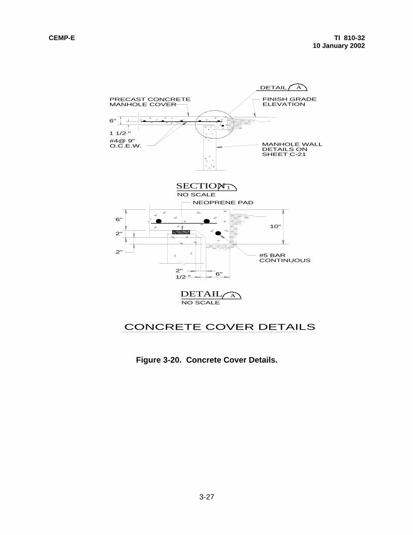
CEMP-E TI 810-32 10 January 2002
3-27
Figure 3-20. Concrete Cover Details.
A
FINISH GRADEELEVATION
PRECAST CONCRETEMANHOLE COVER
DETAIL
6"
1 1/2 "
#4@ 9"O.C.E.W.
1SECTIONNO SCALE
MANHOLE WALLDETAILS ONSHEET C-21
10"
6" 1/2 "2"
6"
2"
2"
NEOPRENE PAD
#5 BARCONTINUOUS
ANO SCALE
DETAIL
CONCRETE COVER DETAILS

CEMP-E TI 810-32 10 January 2002
3-28
Figure 3-21. Gooseneck Detail.
45^
45^(TYP.)
WELD 6" PIPESECTIONS
PAINTED 6"SCHEDULE 40STEEL PIPE
VALVEMANHOLE TOP
24"
12"
18"
TYPICAL GOOSENECK DETAIL
012" 6" 1'SCALE.
. INCH= 1 FOOT1

CEMP-E TI 810-32 10 January 2002
3-29
Figure 3-22. Valve Manhole Floor Drain Detail.
SLOPE VAULT FLOORTO FLOOR DRAIN
NO SCALE
6"
MIN
.
CAST IRON FLOOR DRAIN WITHMETALIC SPHERE OR FLAPPERTYPE BACKWATER VALVE.
4" DRAIN PIPE DRAIN EXTENDED AT UNIFORMSLOPE TO SUMP BASIN OR STORM DRAIN AS INDICATED ON PLANS.
VALVE MANHOLE FLOOR DRAIN
RAISED "HAT TYPE"PIPE SCREEN MOUNTED TO FLOOR DRAIN
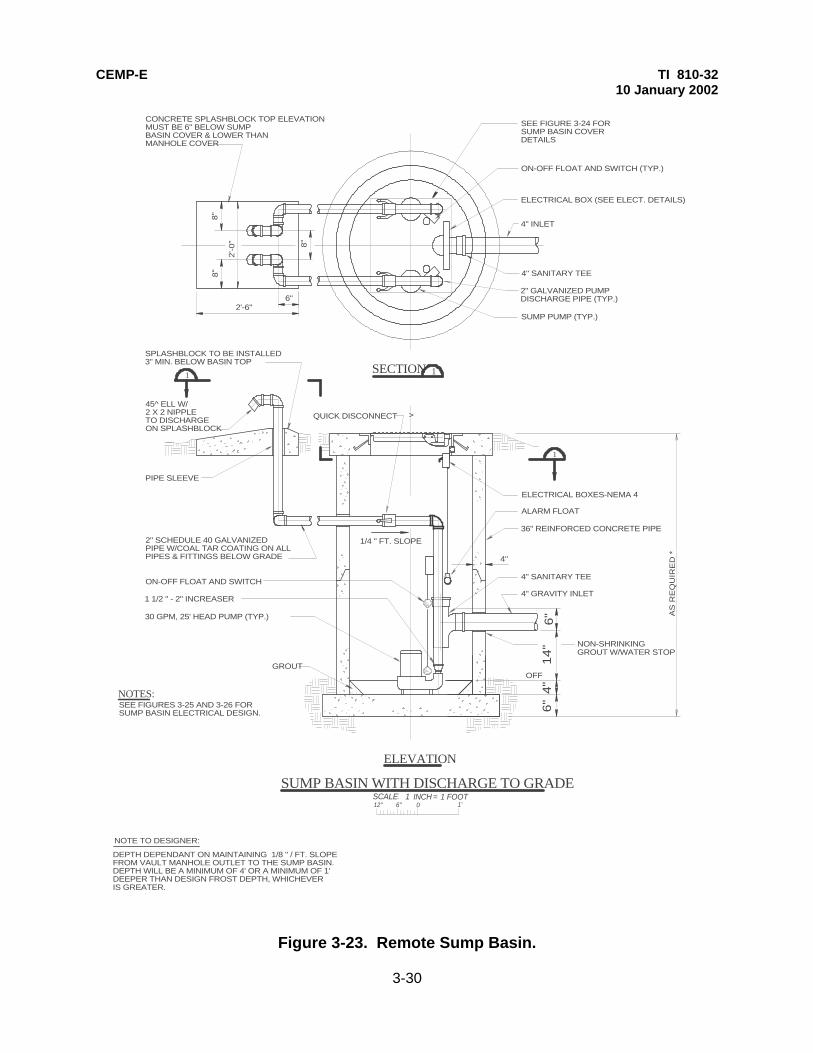
CEMP-E TI 810-32 10 January 2002
3-30
Figure 3-23. Remote Sump Basin.
012" 6" 1'SCALE.
. INCH = 1 FOOT1
ALARM FLOAT
36" REINFORCED CONCRETE PIPE
4" SANITARY TEE
4" GRAVITY INLET
NON-SHRINKINGGROUT W/WATER STOP
1 1/2 " - 2" INCREASER
PIPE SLEEVE
2" SCHEDULE 40 GALVANIZEDPIPE W/COAL TAR COATING ON ALLPIPES & FITTINGS BELOW GRADE
ON-OFF FLOAT AND SWITCH
30 GPM, 25' HEAD PUMP (TYP.)
GROUT
45^ ELL W/2 X 2 NIPPLETO DISCHARGEON SPLASHBLOCK
SPLASHBLOCK TO BE INSTALLED3" MIN. BELOW BASIN TOP
1/4 " FT. SLOPE
4"
>
OFF
NOTES:
CONCRETE SPLASHBLOCK TOP ELEVATIONMUST BE 6" BELOW SUMPBASIN COVER & LOWER THANMANHOLE COVER
SEE FIGURE 3-24 FORSUMP BASIN COVERDETAILS
ON-OFF FLOAT AND SWITCH (TYP.)
ELECTRICAL BOX (SEE ELECT. DETAILS)
4" INLET
4" SANITARY TEE
2" GALVANIZED PUMPDISCHARGE PIPE (TYP.)
SUMP PUMP (TYP.)
8"
8"
8"
6"2'-6"
2'-0
"
1
1
1SECTION
ELEVATION
SUMP BASIN WITH DISCHARGE TO GRADE
6"
4"
14
"6" A
S R
EQ
UIR
ED
*
ELECTRICAL BOXES-NEMA 4
SEE FIGURES 3-25 AND 3-26 FORSUMP BASIN ELECTRICAL DESIGN.
QUICK DISCONNECT
NOTE TO DESIGNER:
DEPTH DEPENDANT ON MAINTAINING 1/8 " / FT. SLOPEFROM VAULT MANHOLE OUTLET TO THE SUMP BASIN. DEPTH WILL BE A MINIMUM OF 4' OR A MINIMUM OF 1' DEEPER THAN DESIGN FROST DEPTH, WHICHEVERIS GREATER.
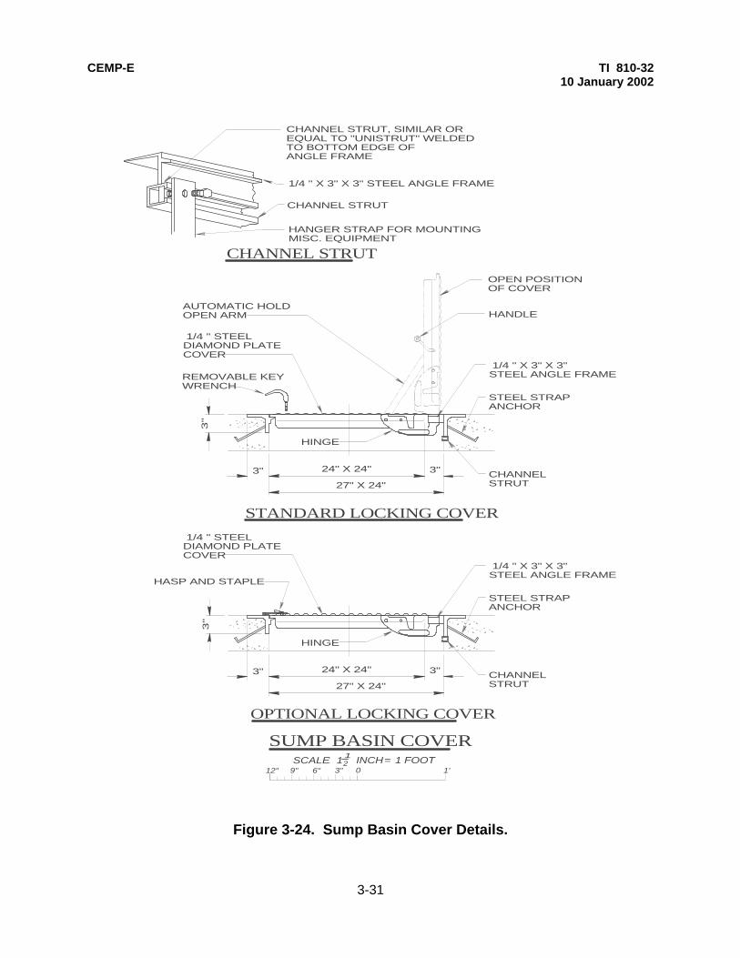
CEMP-E TI 810-32 10 January 2002
3-31
Figure 3-24. Sump Basin Cover Details.
OPEN POSITIONOF COVER
STANDARD LOCKING COVER
12" 6" 3" 0 1'9"
12SCALE.
. INCH= 1 FOOT1
HANDLEAUTOMATIC HOLDOPEN ARM
1/4 " STEELDIAMOND PLATE COVER
REMOVABLE KEYWRENCH
1/4 " X 3" X 3" STEEL ANGLE FRAME
CHANNELSTRUT
STEEL STRAPANCHOR
HINGE
27" X 24"
24" X 24" 3"
3"
3"
OPTIONAL LOCKING COVER
1/4 " STEELDIAMOND PLATE COVER
1/4 " X 3" X 3" STEEL ANGLE FRAME
CHANNELSTRUT
STEEL STRAPANCHOR
HINGE
27" X 24"
24" X 24" 3"
3"
3"
HASP AND STAPLE
CHANNEL STRUT, SIMILAR OREQUAL TO "UNISTRUT" WELDEDTO BOTTOM EDGE OFANGLE FRAME
1/4 " X 3" X 3" STEEL ANGLE FRAME
CHANNEL STRUT
HANGER STRAP FOR MOUNTINGMISC. EQUIPMENT
CHANNEL STRUT
SUMP BASIN COVER
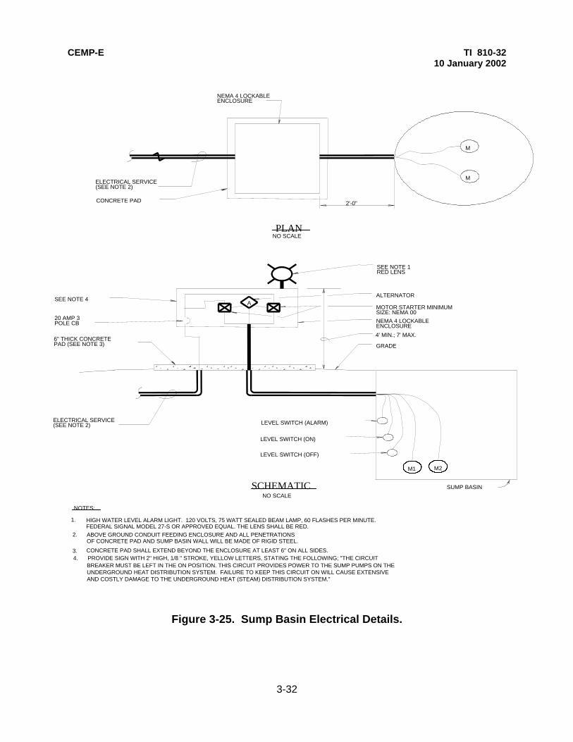
CEMP-E TI 810-32 10 January 2002
3-32
Figure 3-25. Sump Basin Electrical Details.
A
M1 M2
SUMP BASIN
LEVEL SWITCH (OFF)
LEVEL SWITCH (ON)
LEVEL SWITCH (ALARM)ELECTRICAL SERVICE(SEE NOTE 2)
6" THICK CONCRETEPAD (SEE NOTE 3)
20 AMP 3POLE CB
SEE NOTE 4
SEE NOTE 1RED LENS
ALTERNATOR
MOTOR STARTER MINIMUMSIZE: NEMA 00NEMA 4 LOCKABLEENCLOSURE
GRADE
M
M
NEMA 4 LOCKABLEENCLOSURE
ELECTRICAL SERVICE(SEE NOTE 2)
CONCRETE PAD
NO SCALE
NO SCALE
PLAN
SCHEMATIC
2'-0"
NOTES:
HIGH WATER LEVEL ALARM LIGHT. 120 VOLTS, 75 WATT SEALED BEAM LAMP, 60 FLASHES PER MINUTE.FEDERAL SIGNAL MODEL 27-S OR APPROVED EQUAL. THE LENS SHALL BE RED.
1.
2.
3. CONCRETE PAD SHALL EXTEND BEYOND THE ENCLOSURE AT LEAST 6" ON ALL SIDES.4. PROVIDE SIGN WITH 2" HIGH, 1/8 " STROKE, YELLOW LETTERS, STATING THE FOLLOWING; "THE CIRCUIT
BREAKER MUST BE LEFT IN THE ON POSITION. THIS CIRCUIT PROVIDES POWER TO THE SUMP PUMPS ON THEUNDERGROUND HEAT DISTRIBUTION SYSTEM. FAILURE TO KEEP THIS CIRCUIT ON WILL CAUSE EXTENSIVEAND COSTLY DAMAGE TO THE UNDERGROUND HEAT (STEAM) DISTRIBUTION SYSTEM."
4' MIN.; 7' MAX.
ABOVE GROUND CONDUIT FEEDING ENCLOSURE AND ALL PENETRATIONSOF CONCRETE PAD AND SUMP BASIN WALL WILL BE MADE OF RIGID STEEL.

CEMP-E TI 810-32 10 January 2002
3-33
Figure 3-26. Sump Pump Wiring Diagram.
P1
P2
A
P1
P2
LEVEL SW.(ALARM)
LEVEL SW.(OFF)
LEVEL SW.(ON)
R
SIZE ASREQUIRED
P1 P2
OL OL OL OL
M1 M2 3/4 HP 3/4 HP
480 VOLT TO120 VOLT *
OL OL OL
OL OL OL
SEQUENCE OF OPERATION:
THE ALTERNATOR SHALL OPERATE A PUMP UPON WATER LEVEL REACHING LEVEL SWITCH ON ANDDEENERGIZE IT WHEN THE WATER LEVEL FALLS BELOW LEVEL SWITCH OFF. IT SHALL ALTERNATEPUMPS ON EACH SUCCESSIVE CLOSING OF LEVEL SWITCH ON. IF THE WATER CONTINUES TO RISE
SUMP PUMP CONTROL-3 LINE DIAGRAMNO SCALE
TO ALTERNATOR
ACTUAL SYSTEM VOLTAGE AND HORSE POWER REQUIREMENTSMUST BE VERIFIED AND DETAILED FOR EACH DESIGN
R
"POWER ON" LIGHT MOUNTEDON SIDE OF ENCLOSURE
NOTE TO THE DESIGNER:
PAST THE ALARM LEVEL, THE RED LIGHT SHALL BE ENERGIZED AND THE LAG (SECOND) PUMPSHALL BE ENERGIZED.

CEMP-E TI 810-32 10 January 2002
3-34
Figure 3-27. Valve Manhole Sump Pump Electrical Details.
A
M1 M2
LEVEL SWITCH (OFF)
LEVEL SWITCH (ON)
LEVEL SWITCH (ALARM)ELECTRICAL SERVICE(SEE NOTE 2)
6" THICK CONCRETEPAD (SEE NOTE 3)
20 AMP 3POLE CB
SEE NOTE 4
SEE NOTE 1RED LENS
ALTERNATOR
MOTOR STARTER MINIMUMSIZE: NEMA 00
NEMA 4 LOCKABLEENCLOSURE
GRADE
NEMA 4 LOCKABLEENCLOSURE
ELECTRICAL SERVICE(SEE NOTE 2)
CONCRETE PAD
NO SCALE
NO SCALE
PLAN
SCHEMATIC
2'-0"
NOTES:
HIGH WATER LEVEL ALARM LIGHT. 120 VOLTS, 75 WATT SEALED BEAM LAMP, 60 FLASHES PER MINUTE.FEDERAL SIGNAL MODEL 27-S OR APPROVED EQUAL. THE LENS SHALL BE RED.
1.
2.
3. CONCRETE PAD SHALL EXTEND BEYOND THE ENCLOSURE AT LEAST 6" ON ALL SIDES.
4. PROVIDE SIGN WITH 2" HIGH, 1/8 " STROKE, YELLOW LETTERS, STATING THE FOLLOWING; "THE CIRCUITBREAKER MUST BE LEFT IN THE ON POSITION. THIS CIRCUIT PROVIDES POWER TO THE SUMP PUMPS ON THEUNDERGROUND HEAT DISTRIBUTION SYSTEM. FAILURE TO KEEP THIS CIRCUIT ON WILL CAUSE EXTENSIVEAND COSTLY DAMAGE TO THE UNDERGROUND HEAT (STEAM) DISTRIBUTION SYSTEM."
4' MIN.; 7' MAX.
VALVE MANHOLE SUMP ELECTRICAL DETAILS
ABOVE GROUND CONDUIT FEEDING ENCLOSURE AND ALL PENETRATIONSOF CONCRETE PAD AND VALVE MANHOLE WALL WILL BE MADE OF RIGID STEEL.
VALVEMANHOLE
ROUTE 2" DISCHARGE PIPE ASDETAILED FOR SUMP BASINSYSTEM (FIGURE 3-23)
M-2
M-1
VALVEMANHOLE
SUMP PIT(2'x2'x1' (deep)MINIMUM)

CEMP-E TI 810-32 10 January 2002
3-35
Figure 3-28. Casing Wall Penetration Detail.
PIPE SLEEVESEE NOTE 1
SEE NOTE 2
NOTES:
NO SCALE
6"
3"
1/4"
CASING WALL PENETRATION
INSIDE WALL OF MANHOLE
INSULATION ONCARRIER PIPE
WATER STOPWELDED TOSLEEVE
CONDUIT SEAL(SIMILAR OR EQUAL TOLINK-SEAL MODEL - LS)
1" THREADED BRASS CAPOR PLUG
1. END SEAL OR GLAND SEAL SHALL BE PROVIDED ON ALL DDT PRE-ENGINEERED BURY SYSTEMS INSIDE MANHOLE WALLS. CASING AIR SPACE SHALL BE PROVIDED WITH DRAIN PLUG AND VENT. VENT SHALL HAVE 1 " PIPE ROUTED AS INDICATED. 2. INSIDE DIAMETER (ID) OF SLEEVE SHALL BE DETERMINED AFTER CASING OUTSIDE DIAMETER (OD) HAS BEEN VERIFIED. GENERALLY, SLEEVE (ID) SHALL BE 5" MORE THAN CASING OD. VERIFY WITH SEAL MANUFACTURER.
CASING OF EXISTINGDDT PRE-ENGINEEREDUNDERGROUND HEATDISTRIBUTION SYSTEM
EXTEND 1" PIPE 12" ABOVETOP OF MANHOLE (OR NEARTOP OF SUPPORTED COVER OR RAISED SOLID PLATE COVER MANHOLES)

CEMP-E TI 810-3210 January 2002
3-37
RECOMMENDED INTERNAL CLEARANCES
MINIMUMDISTANCE(INCHES)FROMTO
O.D. OFPIPEINSULATIONORCONDUIT
END OFVALVESTEM ORBODY
ELEC.EQUIP.
LADDER
BOTTOMOF TRAPSTATIONOR DRAIN
WALL
FLOOR
TOP OFMANHOLE
18"
24"
18"
18" 18"
24"
12"
12" 12"
6" 6"
6"
36"
36"
-
VALVE MANHOLE CLEARANCES
NOTES:1. IN ADDITION TO THE CLEARANCES FOR THE LADDER INDICATED PROVIDE 24" AROUND THE LADDER FOR MAINTENANCE ACCESS. 2. PROVIDE 24" AROUND SIDES OF MANHOLE DRAIN TO ALLOW FOR CLEANING OF DEBRIS.
Table 3-1. Valve Manhole Clearances.

CEMP-E TI 810-3210 January 2002
3-38
VALVE MANHOLE REINFORCEMENT SCHEDULE
MAXIMUM DIMENSION* WALL REINFORCEMENT SLAB REINFORCEMENT
OUTSIDEL1XW1
INSIDEL2XW2 HORIZONTAL VERTICAL BOTTOM
PRINCIPALTOP**PRINCIPAL
BOTTOMSECONDARY
TOPSECONDARY
9'4"X9'4"
15'4"X15'4"
8'0"X8'0"
14'0"X14'0"
#5@10"
#5@6"
#5@12"
#5@10"
#5@10"
#5@10"
#4@18"
#4@18"
#4@18"
#4@18"
#4@18"
#4@18"
* L1,L2,W1, AND W2 DIMENSIONS FROM FIGURE 3-5. MAXIMUM DEPTH (H1) FOR THIS TABLE IS 8'0"
** PRINCIPAL REINFORCEMENT WILL SPAN THE SHORTER DIMENSION
VALVE MANHOLE REIN. STEEL SIZES
Table 3-2. Reinforcing Steel Sizes.
REINFORCED CONCRETE DESIGN IS BASED ON THE FOLLOWING:
1. LOADS : 200 psf SURCHARGE ADJACENT TO VAULT.2. SOIL PROPERTIES = MOIST = 120 pcf WATER TABLE 2' BELOW SURFACE SATURATED = 125 pcf BEARING CAP. = 1500 psf. MIN. Ko = .80
NOTES TO THE DESIGNER:

CEMP-E TI 810-3210 January 2002
3-39
Table 3-3. Sump Pump Checklist.
SUMP PUMP CHECKLIST
ITEM PUMPS' DESCRIPTION
1.
2.
3.
4.
5.
6.
7.
8.
9.
10.
11.
ELECTRICALLY DRIVEN.
DUPLEX SYSTEM WITH ALTERNATOR.
DEDICATED ELECTRICAL SERVICE.
SUBMERGED OPERATION IN 200^F WATER.
ENTIRE PUMPING SYSTEM CAPABLE OF200,000 CYCLES OF OPERATION IN200^F, 100% RELATIVE HUMIDITY ENVIR.
PERMANANTLY LUBRICATED BEARINGS.
MONEL SHAFT.
BRONZE IMPELLER.
CAPABLE OF PASSING 3/8 INCH SPHERES.
SCREENED INLET.
BRONZE HOUSING.

CEMP-E TI 810-32 10 January 2002
4-1
CHAPTER 4
HEAT DISTRIBUTION SYSTEMS IN CONCRETE TRENCHES
4-1. GENERAL. The concrete shallow trench (CST) is a system, which allows insulated carrier pipes to be routed underground but yet not have the piping in contact with the soil. The system also provides comparatively easy access for maintenance and repair by means of removable concrete tops. These exposed tops can be used as sidewalks since the system is installed at grade. 4-2. SYSTEM DESIGN. The designer is responsible for conducting a site investigation, designing the distribution system plan and profiles, and designing the valve manholes, as described in chapter 3 of this manual. In addition, the designer will use details and descriptions presented here to design a concrete shallow trench system at a particular site. a. Trench Systems - General. (1) Piping and fittings. All carrier piping and pipe fittings will be carbon steel and will be designed to satisfy the temperature and pressure requirements of the system. Materials will conform to the requirements in the guide specification. (2) Pipe supports. Pipe supports will typically consist of three types: free, guided, and anchor. These supports are detailed in figure 4-1, figure 4-2, and figure 4-3. All of these pipe supports will be mounted on channel supports mounted to the trench walls as detailed in figure 4-4. Supports may be mounted by other means, such as on concrete pedestals, provided that paths for water flow are maintained. Table 4-1 provides guidance for the sizing of the channel supports. Note that the channels for anchor supports in the table are designed for more substantial loads than required for free and guided supports. The anchor support channel in this table is adequate for approximately 1,000 pounds force axially. The designer will determine axial force requirements at all anchor points and design the channels to accommodate these forces. \1\ Maximum distance between support channels shall be as listed in table 4-2. /1/ These spacings are applicable to long, straight runs of piping only and must be reduced at elbows, vertical risers, valving, and equipment. The actual spacings, in these instances, will be determined by analyzing the pipe stresses with the pipe stress analysis, as described in chapter 3 of this manual. The designer should note that there are other types of supports (such as roller type) that may also be used. However, all supports must be capable of withstanding the thermal stresses and forces exerted on them. (3) Clearances. Clearances in the trench will be adequate to provide room for expansion, air movement, and a sufficient amount of access for cleaning and maintenance. There must also be a minimum of 4 inches clearance under the support channels to ensure ground water drainage along the trench floor. Figure 4-5 provides a trench cross-section, which corresponds to the table 4-3 trench dimension schedule, which must be filled in by the designer. (4) Insulation and jacketing. Insulation will be selected in accordance with insulation thickness tables in the guide specification. These insulation thicknesses were developed using a life cycle cost analysis. All insulations used have passed the Federal Agency Committee's boiling test and are listed in the guide specifications. All insulation in the trench will be covered with jacketing material in conformance to the guide specification. b. Trench System - Structural. The concrete trench will be field constructed of reinforced concrete conforming to the current criteria. Trench walls and floors will be poured in place-they will not be precast. Trench tops will be poured in place or precast. Walls, floors, and tops will be constructed with 4,000 psi minimum compressive strength concrete. Reinforcing bars will conform to ASTM A 615, grade 60. Wall,

CEMP-E TI 810-32 10 January 2002
4-2
floor, and top thicknesses shall be 6 inches, minimum. However, thicker sections may be required to accommodate site specific loadings or to prevent flotation. Concrete trench floors shall be sloped at a 1 inch in 20 feet slope toward all low points to ensure proper drainage. Doweled or keyed joints and water stops shall be provided at all construction joints and shall be detailed as shown in figure 4-6. Trench reinforcing details will be provided and will be similar to the section shown in figure 4-7. Note that actual concrete thicknesses and reinforcing bar sizes will be verified by the designer for each project. Trench corners will be constructed as detailed in figure 4-8. Trench tops will be no longer than eight feet to allow easy removal and placement. c. Trench Top Removal Devices. The most common type of removal devices for the trench tops will be the sling type as detailed in figure 4-9. Four lifting devices are required to lift a trench top. One set of lifting devices will accommodate all trench tops for each contract. In some instances, sling type lifting devices will not be convenient to use (eg. when the trench top butts up against a parallel sidewalk or when the trench is routed through a parking area). In these instances, the designer shall require coil inserts to be cast into the trench cover in four locations that will accommodate threaded lifting eye bolts. When not being used, threaded plugs are inserted into the coil inserts. The lifting devices are also detailed in figure 4-9. d. Road and Parking Lot Crossings. Road crossing requirements will be designed on a case by case basis and must take into account pavement materials, soils, and frost characteristics of the design site. A typical road crossing is shown in figure 4-10. Figure 4-11 details a concrete trench to curb and gutter system transition and figure 4-12 details a concrete trench to drain pan system transition. In all instances, the crown of the road crossing will be matched and the thickness of the trench top will be designed to accommodate worst case loadings. Parking lot crossings typically will have the trench top exposed at grade as shown in figure 4-13. Exposed tops allow for easier trench top removal over extended lengths of paved areas. If appearance of the crossing is critical, black pigments may be added to the concrete tops at the road crossing to match the surrounding pavement. In rare instances, the trench tops may be covered with asphalt surfacing, as detailed in figure 4-14. e. Sidewalk Intersections. In the event the trench system intersects an existing sidewalk, the trench system will match the sidewalk as detailed in figure 4-15. f. Expansion Compensation. Expansion loop and bend design is the responsibility of the designer, and is covered in chapter 3 of this manual. The expansion loop design is critical. Sufficient space needs to be provided in the expansion loop area to ensure that no pipe or insulation interference will occur due to pipe movement as shown in figure 4-16. This detail indicates location of supports and also shows how the piping system will be offset to allow for expansion movement in the trench. Table 4-4 is a typical loop schedule, which corresponds to figure 4-16. The locations of the supports in the expansion loops will be determined from the designer's piping stress analysis and then entered in Table 4-4. All piping stresses will be less than ASME B31.1 allowables for each application. The designer will require inspection ports be provided in the trench tops at each bend in the trench system routing for the purpose of observing pipe movement at the bends during system startup. The inspection port is similar to the access cover detailed in figure 4-18, except the nominal diameter of the lid will be 12 inches. g. Sealants. The trench will be sealed to minimize the influx of ground water. A 1/4 inch thick neoprene pad will be used between trench tops and tops of trench walls. The pad will have a minimum width of 2 inches. All trench joints must be sealed with elastomeric sealants, which are available as a one or two component system. Asphaltic sealants have not performed as reliably for this application. The elastomeric sealant should be able to resist 50 percent total joint movement. The nonsagging type must be used for vertical joints. The self-leveling type must be used for trench top butt joints as shown in figure 4-17. Other horizontal joints may be sealed with either type of elastomeric sealant, but the sealant used in trench bottoms must finish flush with the floor.

CEMP-E TI 810-32 10 January 2002
4-3
h. Vents and drains. Piping vents and drains will be located at all high and low points, respectively \1\ (see figure 4-19) /1/. Piping drains will be provided in valve manholes only where access can be achieved and where system drainage is provided. Piping vents may be located anywhere in the trench piping system with an access cover provided in the trench top, as detailed in figure 4-18 or with an aluminum access door shown in figure 3-19. 4-3. GENERAL CONSIDERATIONS. The designer will address these key areas to ensure a satisfactory shallow trench design. a. The grading design will ensure ground water will not pond or sit over the trench. The trench will not be routed through existing flood plains, swales, or in areas where seasonal water accumulates. Another distribution system, preferably an Aboveground Heat Distribution System (chap 7), should be used in these areas. In areas where seasonal ground water will cause a trench flotation problem, the design will include a subdrainage system along the trench if thickening of system walls and floor slabs to offset the buoyancy effect is not practical. b. The trench floors will slope a minimum of 1 inch in 20 feet toward valve manholes and the piping will parallel the trench floor. This will allow the trench to drain off all water that may enter. Drainage will then be provided from the valve manholes as described in chapter 3 of this manual. c. Valve manholes should be spaced to minimize the depth of the trench system. Additional manholes may be less expensive than excessive trench depths to accommodate the slope while still keeping the trench tops at grade.
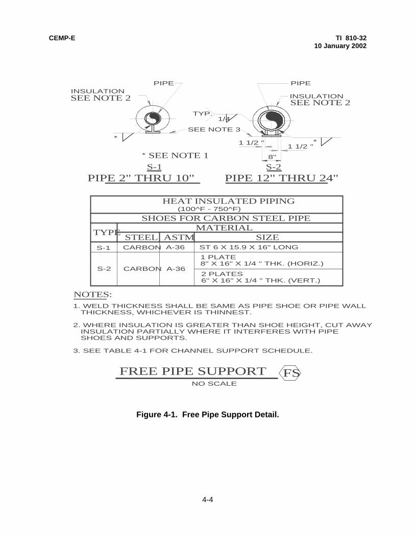
CEMP-E TI 810-32 10 January 2002
4-4
Figure 4-1. Free Pipe Support Detail.
INSULATIONPIPE
SEE NOTE 2
S-1 S-2PIPE 2" THRU 10" PIPE 12" THRU 24"
INSULATIONSEE NOTE 2
PIPE
8"
1 1/2 "1 1/2 "
*
1/4 TYP.
*
SEE NOTE 1*
HEAT INSULATED PIPING
TYPESTEEL ASTM SIZE
SHOES FOR CARBON STEEL PIPEMATERIAL
S-1
S-2
CARBON
CARBON A-36
A-36 ST 6 X 15.9 X 16" LONG
1 PLATE 8" X 16" X 1/4 " THK. (HORIZ.)
2 PLATES 6" X 16" X 1/4 " THK. (VERT.)
FREE PIPE SUPPORT FSNO SCALE
(100^F - 750^F)
NOTES:
SEE NOTE 3
1. WELD THICKNESS SHALL BE SAME AS PIPE SHOE OR PIPE WALL THICKNESS, WHICHEVER IS THINNEST. 2. WHERE INSULATION IS GREATER THAN SHOE HEIGHT, CUT AWAY INSULATION PARTIALLY WHERE IT INTERFERES WITH PIPE SHOES AND SUPPORTS. 3. SEE TABLE 4-1 FOR CHANNEL SUPPORT SCHEDULE.

CEMP-E TI 810-32 10 January 2002
4-4
INSULATIONPIPE
PIPE 2"THRU 10"
INSULATION
PIPE
HEAT INSULATED PIPING
TYPESTEEL ASTM SIZE
MATERIAL
G-4
G-5
CARBON
CARBON A-36
A-36
NO SCALE
GUIDE ANGLE(TYP.)
G-4S-1SEE NOTE 1
TYP. 3/16 1 1/2 "-3
TYP. 3/16 1 1/2 "-3
S-2SEE NOTE 1
G-5
GUIDE ANGLE(TYP.)
1/4 " CLR. (TYP.)
1/4 " CLR. (TYP.)
GUIDES FOR PIPE SHOE
1" X 1" X 3/16 "ANGLE 16" LONG
1" X 1" X 3/16 "ANGLE 16" LONG
1. FOR PIPE SHOES S-1 AND S-2,
SEE DETAILS FOR ,(Fig. 4-1)
GUIDED PIPE SUPPORT
NOTE:
SUPPORT CHANNELIN TRENCH (TYP.)(SEE NOTE 2)
2. SEE TABLE 4-1 FOR CHANNEL SUPPORT SCHEDULE.
Fig. 4-2. Guided Pipe Support Detail.
PIPE 12"THRU 24"

CEMP-E TI 810-32 10 January 2002
4-6
Figure 4-3. Pipe Anchor Detail.
INSULATION
PIPE
PIPE 2" THRU 10" PIPE 12" THRU 24"
INSULATIONSEE NOTE 1
PIPE
1/4 TYP.
ASNO SCALE
1/4 TYP.
S-1
S-2SEE NOTE 1
NOTE:
ANCHOR PIPE SUPPORT
2. SEE TABLE 4-1 FOR CHANNEL SUPPORT SCHEDULE.
SUPPORT CHANNELIN TRENCH (TYP.)(SEE NOTE 2)
SEE DETAILS ON FIGURE 4-1.
1. FOR PIPE SHOES S-1 AND S-2

CEMP-E TI 810-332 10 January 2002
4-7
Figure 4-4. Pipe Support Channel.
1
VARIES
SUPPORT CHANNEL
>
6"
SYMMETRICAL ABOUT >
2
NOTE:SEE FIGURE 4-5 FOR SECTION 1
NO SCALE
COMPOSITE PLAN - TRENCH
VARIES
CSEE DETAILL
CHANNEL
6"
C
2SECTIONNO SCALE
NO SCALE
ANGLE
3/16
PIPE SUPPORT CHANNEL
DETAIL
1/2
O
F I
NS
IDE
TR
EN
CH
WID
TH
BACKFILLMATERIAL
CHANNELSUPPORT
TWO A307BOLTS
PLATE W/WELDED ANCHORSTUDS (SEE TABLE 4-1 FORNUMBERS AND SIZES)
1/2" PEMBEDDED INTRENCH WALL
NOTE: THE CHANNEL SUPPORT MAY LAY ON TOPOF THE ANGLE RATHER THAN BEING SUSPENDEDBELOW THE ANGLE AND HELD ON BY BOLTS AS SHOWN. PLACING THE CHANNEL ON TOP WOULD ALLOW THE ANGLE TO SUPPORT THE CHANNEL AND THE BOLTS WOULD HOLD THE CHANNEL IN POSITION
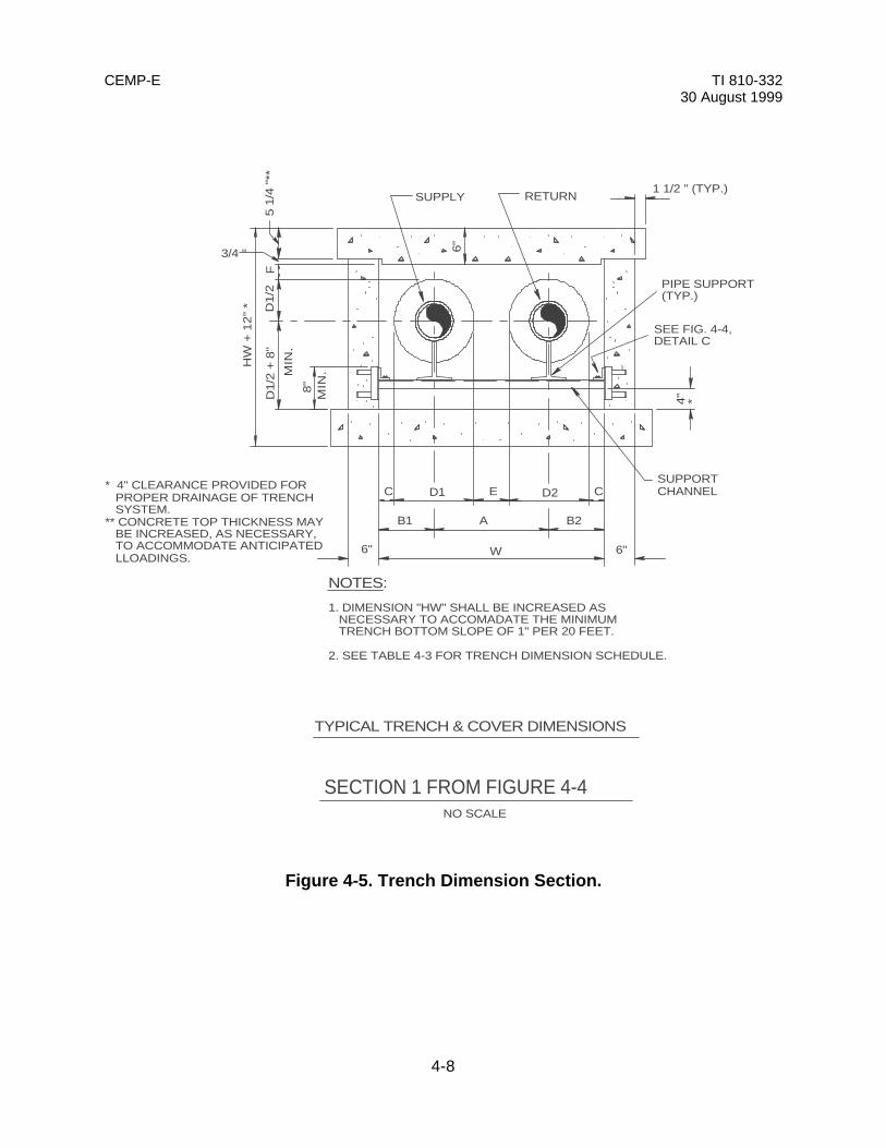
CEMP-E TI 810-332 30 August 1999
4-8
Figure 4-5. Trench Dimension Section.
RETURN
C E D2 CD1
B1 A B2
6" W 6"
4"
8"M
IN.
1 1/2 " (TYP.)
6"
F
HW
+ 1
2"
*
MIN
.
TYPICAL TRENCH & COVER DIMENSIONS
NO SCALE
NOTES:
*
D1/2
D1/2
+ 8
"5 1
/4 "
** 3/4 "
SUPPLY
PIPE SUPPORT(TYP.)
SUPPORTCHANNEL
1. DIMENSION "HW" SHALL BE INCREASED AS NECESSARY TO ACCOMADATE THE MINIMUM TRENCH BOTTOM SLOPE OF 1" PER 20 FEET. 2. SEE TABLE 4-3 FOR TRENCH DIMENSION SCHEDULE.
* 4" CLEARANCE PROVIDED FOR PROPER DRAINAGE OF TRENCH SYSTEM.** CONCRETE TOP THICKNESS MAY BE INCREASED, AS NECESSARY, TO ACCOMMODATE ANTICIPATED LLOADINGS.
SEE FIG. 4-4,DETAIL C
SECTION 1 FROM FIGURE 4-4
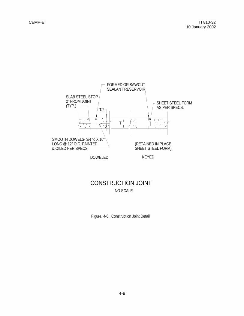
CEMP-E TI 810-3210 January 2002
4-9
NO SCALE
CONSTRUCTION JOINT
(RETAINED IN PLACESHEET STEEL FORM)
SLAB STEEL STOP2" FROM JOINT(TYP.)
FORMED OR SAWCUTSEALANT RESERVOIR
SHEET STEEL FORMAS PER SPECS.
/
DOWELED KEYED
T
T/2
Figure. 4-6. Construction Joint Detail
SMOOTH DOWELS- 3/4 "o X 16"LONG @ 12" O.C. PAINTED& OILED PER SPECS.

CEMP-E TI 810-3210 January 2002
4-10
STD. SIDEWALKEDGE
BROOM FINISH
1" CLEAR
1/4 " NEOOPRENEPAD (TYP.)
2 1/2 " CLEAR
2 1/2 " CLEAR
W.W.F. 6X6-W1.4XW1.4
#4 BARS@8" O.C.
#4 BARS@16" O.C.
#5 BARS@12" O.C.
NO SCALE
* SEE TABLE 4-3 FOR TRENCHDIMENSION SCHEDULE.
TRENCH & COVER REINFORCING
#4 BARS@12" O.C. 6" TYP. MIN.
TRENCH REINFORCEMENT AND CONCRETE THICKNESS SHALLDE DETERMINED BY A STRUCTURAL ENGINEER BASED ON SITESPECIFIC LOADS AND SOIL PROPERTIES. REINFORCEMENTSHOWN IS THE MINIMUM REQUIRED.
NOTE TO THE DESIGNER:
1" CLEAR
Figure 4-7. Typical Trench Section.

CEMP-E TI 810-3210 January 2002
4-11
NO SCALE
24"
24"
#4 CORNER BAR@ 12" O.C.
#4@12" O.C.HORIZ. WALLREINFORCEMENT
TYPICAL TRENCH WALLCORNER REINFORCING
Figure 4-8. Trench Corner Detail.

CEMP-E TI 810-3210 January 2002
4-12
LIFTING SLOT 4" DEEPTYPICAL AT 4 CORNERS
h*
1'-0"
8"
JOINT SEALANT
TOP SLAB JOINT
ACCOMMODATE SUBMITTED LIFTING DEVICE.
LIFTING SLOT (TYP.)
GOVERNMENT AT END OF CONTRACT.
8"
* DESIGN HEIGHT "h" OF SLOT TO
NO SCALE
NOTES:
2. CONTRACTOR SHALL DISTRIBUTE LOAD EQUALLY BETWEEN THE FOUR LIFTING DEVICES BY USING A STRONGBACK OR APPROVED EQUAL.
SECTION SIDE VIEW
1'-0"
TRENCH COVER(TYP.)
TRENCH COVER(TYP.)
TRENCH WALL
REQUIREMENTS ALONG LIFTING SLOTS.1. DESIGN OF LIFTING DEVICE SHALL SATISFY ACI SHEAR
STEEL LIFTING DEVICE W/ SLING BY CONTRACTOR. DELIVER 1 SET OF 4 TO
NO SCALE
SECTION
MINIMUM EYE BOLT REQUIREMENTS
3"
SLING LIFTING DEVICE
3/4 "
3 5/16 " MIN
NOTE:PROVIDE 1 SET OF 4 OF EACHEYE BOLT TYPE TO GOVERNMENTAT END OF CONTRACT.
NO SCALE
NO SCALE
EYE BOLT LIFTING DEVICE
HEAVILY GREASED SETTING PLUG (MANUFACTURED BY DAYTON-SUPERIOR TYPE T-7 OR APPROVED EQUAL)SETTING PLUG SHALL REMAIN INSERTED UNTIL REMOVED BY THE OWNER. IF THE USE OF THE COIL INSERTS IS REQ'D FOR COVER INSTALLATION, THE CONTRACTOR SHALL RE-GREASE SETTING PLUG AND INSERT INTO COIL INSERT AFTER COVER INSTALLATION IS COMPLETE. INSTALL4 INSERTS PER COVER EACH 12" FROMTHE TRENCH TOP SIDE AND 12" FROMTRENCH TOP END.
NOTE:DETAIL APPLIES FOR TRENCH COVERS AT ALL ROAD CROSSINGS, AND AT ALL PARKING LOT CROSSINGS. DETAIL ALSO APPLIES TO ALL TRENCH COVERS THAT BUTT UP TO BACK OF CURBS, AND ANY OTHER AREAS THAT WOULD RESTRICT THE USE OF THE STANDARD LIFTING DEVICES. LIFTING SLOTS SHALL BE PROVIDED IN ALL TRENCH COVERS REGARDLESS OF WHETHER COIL INSERTS ARE USED OR NOT.
FIGURE 4-9. TYPICAL LIFTING DEVICES.
3/4 "o X 6" LENGTH COIL INSERT FOR8" COVERS OR 3/4 "o X 4" LENGTHCOIL INSERT FOR 6" COVERS ASMANUFACTURED BY DAYTON-SUPERIORTYPE B-17 OR APPROVED EQUAL. MIN. TENSILE CAPACITY SHALL BE 4500 lbs.

CEMP-E TI 810-32 10 January 2001
3
>
CENTERLINEOF ROAD
NO SCALE
SECTION 3NO SCALE
BA SEE DETAILSEE DETAIL FIGURE 4-11FIGURE 4-12
TRENCH ROAD CROSSING
3" MIN.
>
Fig. 4-10. Typical Trench Road Crossing.
3
CENTERLINEOF ROAD
NO SCALE
SECTION 3NO SCALE
BA SEE DETAILSEE DETAILFIGURE 4-11FIGURE 4-12
TRENCH ROAD CROSSING
3" MIN.
C
Fig. 4-10. Typical Trench Road Crossing.
L
CL
4-13
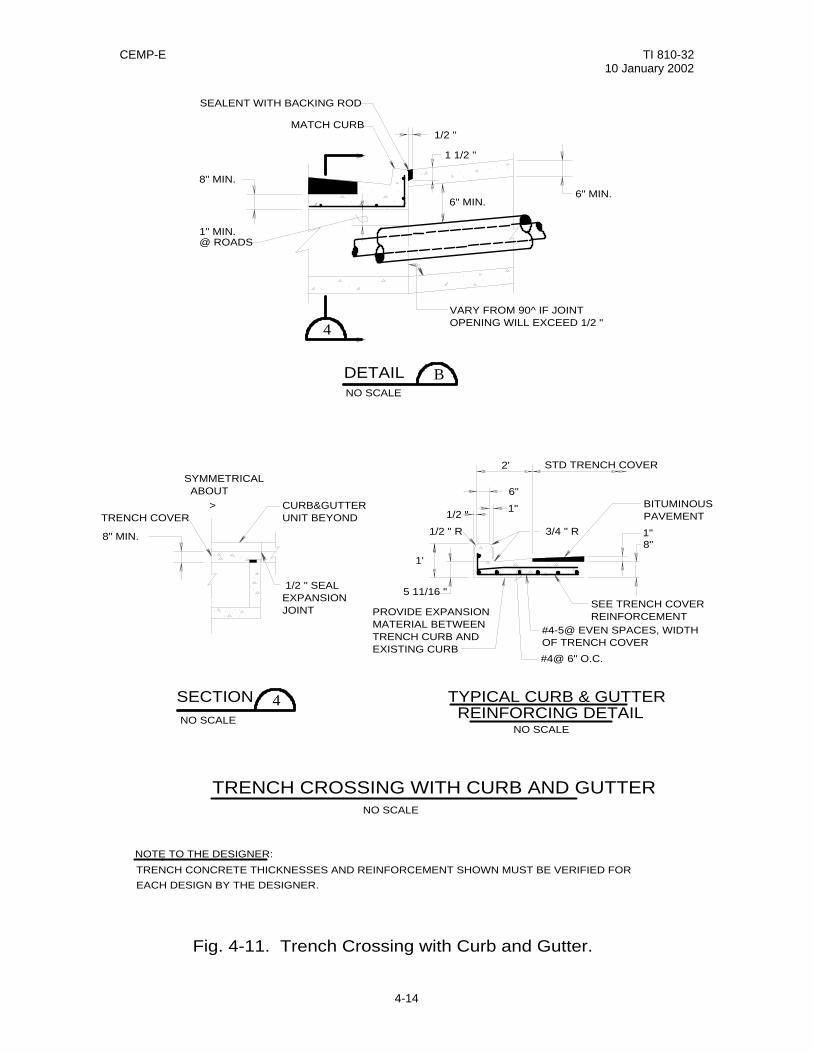
CEMP-E TI 810-32 10 January 2002
4
1/2 "
SEALENT WITH BACKING ROD
6" MIN.6" MIN.
8" MIN.
1" MIN.@ ROADS
1 1/2 "
MATCH CURB
NO SCALE
B
VARY FROM 90^ IF JOINTOPENING WILL EXCEED 1/2 "
>
SYMMETRICAL ABOUT
TRENCH COVER
8" MIN.
CURB&GUTTERUNIT BEYOND
1/2 " SEAL EXPANSIONJOINT
8"1"
1'
5 11/16 "
1" 1/2 "
6"
1/2 " R
2' STD TRENCH COVER
3/4 " R
BITUMINOUSPAVEMENT
SEE TRENCH COVERREINFORCEMENT
#4-5@ EVEN SPACES, WIDTHOF TRENCH COVER
#4@ 6" O.C.
PROVIDE EXPANSION MATERIAL BETWEEN TRENCH CURB AND EXISTING CURB
NO SCALE
4
NO SCALE
Fig. 4-11. Trench Crossing with Curb and Gutter.
DETAIL
SECTION TYPICAL CURB & GUTTER REINFORCING DETAIL
TRENCH CROSSING WITH CURB AND GUTTER
NOTE TO THE DESIGNER:
NO SCALE
TRENCH CONCRETE THICKNESSES AND REINFORCEMENT SHOWN MUST BE VERIFIED FOR
EACH DESIGN BY THE DESIGNER.
4-14

CEMP-E TI 810-32 10 January 2002
6"MIN 1"MIN @ ROADS
1"MIN
MATCH EXISTING DRAIN PAN
8"MIN
NO SCALEADETAIL
1"MIN
7"
3'-0"
1'-6" 1'-6"
STD TRENCH COVER
SEE TRENCHCOVER REINF.
#4@ 6" O.C. #4-5@ EVEN SPACESWIDTH OF TRENCHCOVER
TRENCH CONCRETE THICKNESSES AND REINFORCEMENT SHOWNMUST BE VERIFIED FOR EACH DESIGN BY THE DESIGNER.
Fig. 4-12. Trench Crossing With Drain Pan.
TRENCH CROSSING WITH DRAIN PAN
NO SCALEDRAIN PAN REINF.
NOTE TO THE DESIGNER:
4-15
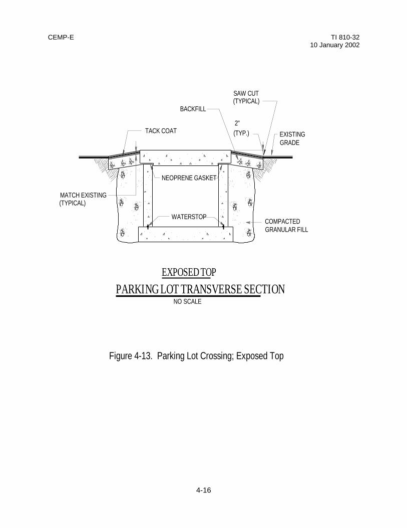
CEMP-E TI 810-3210 January 2002
4-16
TACK COAT EXISTINGGRADE
SAW CUT(TYPICAL)
COMPACTEDGRANULAR FILL
2"
MATCH EXISTING(TYPICAL)
WATERSTOP
NEOPRENE GASKET
(TYP.)
BACKFILL
P A R K I N G L O T T R A N S V E R S E S E C T I O NE X P O S E D T O P
NO SCALE
Figure 4-13. Parking Lot Crossing; Exposed Top
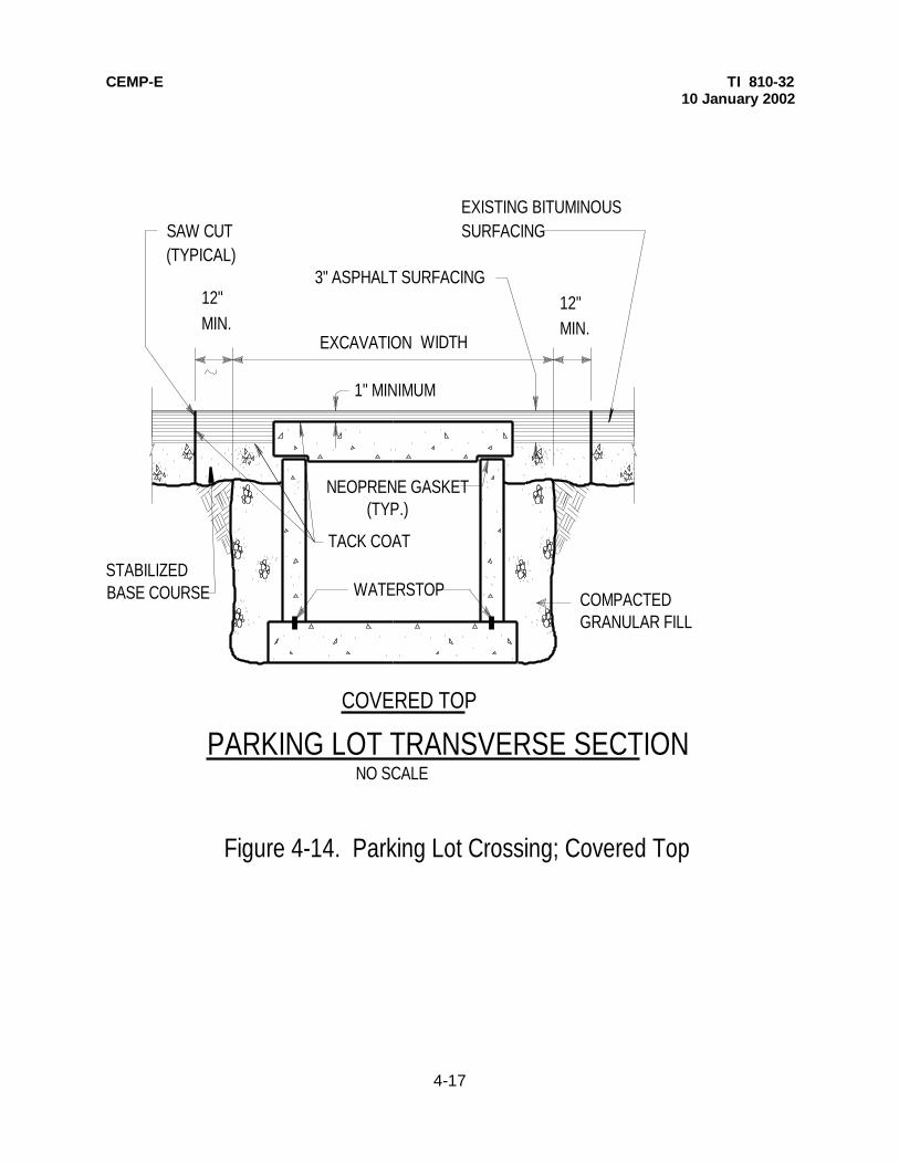
CEMP-E TI 810-3210 January 2002
4-17
COMPACTEDGRANULAR FILL
12"MIN.
EXCAVATION WIDTH
3" ASPHALT SURFACING
1" MINIMUM
12"MIN.
TACK COAT
SAW CUT(TYPICAL)
STABILIZEDBASE COURSE WATERSTOP
NEOPRENE GASKET(TYP.)
NO SCALE
EXISTING BITUMINOUSSURFACING
PARKING LOT TRANSVERSE SECTIONCOVERED TOP
Figure 4-14. Parking Lot Crossing; Covered Top

CEMP-E TI 810-3210 January 2002
4-18
EXISTING
SIDEWALK
EXISTING CONSTRUCTIONJOINT LOCATION
EXISTING
SIDEWALK
COMPACTEDBACKFILL
MATCH EXISTINGSIDEWALK(TYPICAL)
1/2 " EXPANSION JOINT
MATERIAL, TYPICAL
WATERSTOP
NEOPRENE GASKET
SIDEWALK TRANSVERSE SECTIONNO SCALE
Figure 4-15. Sidewalk Transverse Section Detail.

CEMP-E TI 810-32 10 January 2001
4-19
FS
EXPANSION LOOPNO SCALE
FSFS
FS
FS
FS
FS
A B2+4B1-4 AB2+4 B1-4
"U"
SEE PLANS FOR STATIONING
SEE PLAN FORSUPPORT TYPESAND LOCATIONS "X"
SEE PLAN FORSUPPORT TYPESAND LOCATIONS"X"
AB1 B2
B2
-2
AB
1+
2
"H"
SEE FIG. 4 1
FREE SUPPORT(TYP.),
"Z" "Z""ZZ"
SYMMETRICALABOUT >
"Y"
"YY
""Y
"
COVERED TRENCH
"W"
TYPICALBOTH SIDES
NEW 4" CONCRETESIDEWALK FILLER, INSTALL AT LOOP
NOTES:
Fig. 4-16. Expansion Loop Detail.
ANCHOR TO ANCHOR DISTANCE VARIES -
1. DIMENSIONS A, B, AND B2 ARE FROM THE "TRENCH DIMENSION SCHEDULE", TABLE 4 3. 2. DIMENSIONS Z,ZZ,Y,YY,W,H,X, AND U ARE FROM THE "EXPANSION LOOP SCHEDULE", TABLE 4-4.
FSFS
GS
BETWEEN THE FIRST AT THE LOOP AND THE ANCHOR, ALTERNATE AND (FIGURES 4-2 AND 4-3) TO KEEP PIPING SYSTEM CENTERED IN TRENCH.
NOTE TO THE DESIGNER:
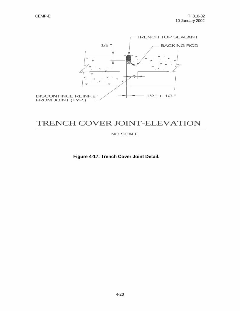
CEMP-E TI 810-32 10 January 2002
4-20
Figure 4-17. Trench Cover Joint Detail.
1/2 "
- 1/2 " + 1/8 "
TRENCH TOP SEALANT
BACKING ROD
NO SCALE
TRENCH COVER JOINT-ELEVATION
DISCONTINUE REINF.2"FROM JOINT (TYP.)
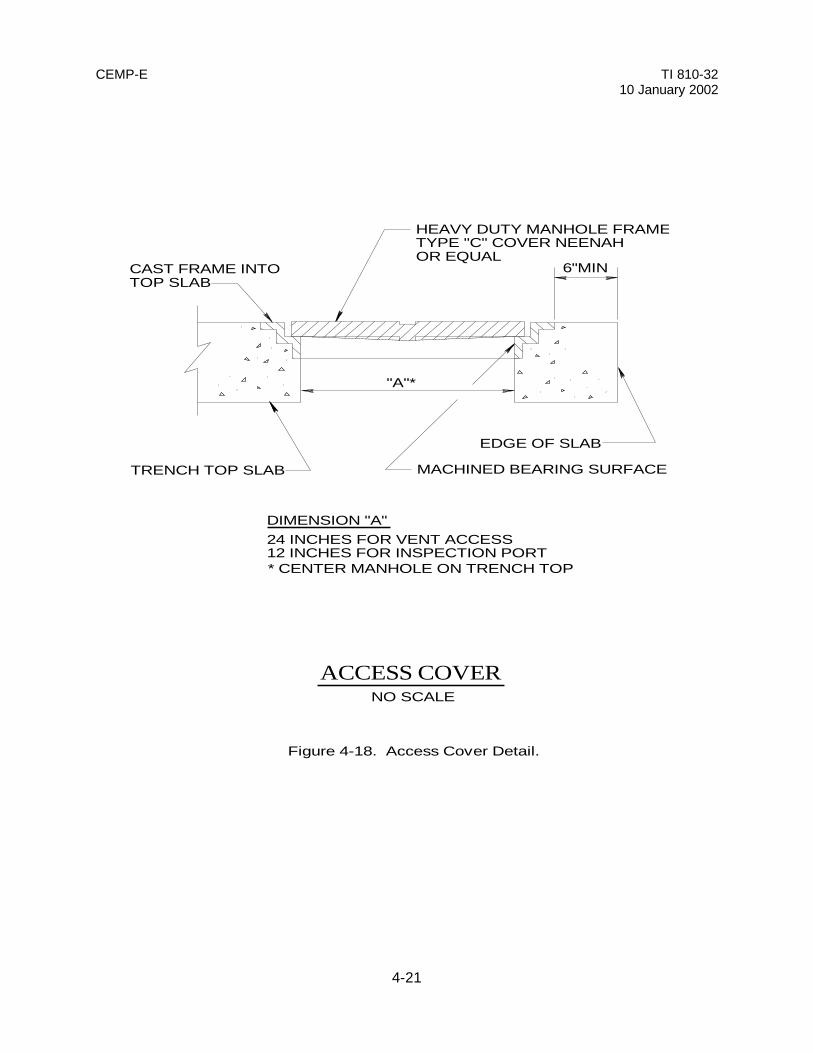
CEMP-E TI 810-3210 January 2002
4-21
6"MINCAST FRAME INTOTOP SLAB
HEAVY DUTY MANHOLE FRAME &TYPE "C" COVER NEENAHOR EQUAL
MACHINED BEARING SURFACE
EDGE OF SLAB
TRENCH TOP SLAB
"A"*
DIMENSION "A"24 INCHES FOR VENT ACCESS12 INCHES FOR INSPECTION PORT* CENTER MANHOLE ON TRENCH TOP
NO SCALE
ACCESS COVER
Figure 4-18. Access Cover Detail.

CEMP-E TI 810-3210 January 2002
4-22
1" SCHED 80 PIPE
1" GLOBE VALVE
1/2 " GLOBE VALVE
THREADED PIPE CAP,DO NOT SEAL WELD
CAP(DO NOT WELD)
LOW POINT
WELD
SOCKET WELD
PITCH DOWNTO DRAIN
NO SCALE
HIGH POINT
1/2 " SOCKOLET
SOCKET WELD
LOW POINTS IN ALL PIPING TOBE DRAINED.
NOTE:
DRAIN
NO SCALEVENT
VENT AND DRAIN DETAILS
Figure 4-19. Vent and Drain Details.
THREADED PIPE 1/2 "OSCHED. 80

CEMP-E TI 810-32 10 January 2002
4-23
Table 4-1. Channel Support Schedule * LOCATION
PLATE
ANCHOR STUDS
ANGLE
CHANNEL
BOLTS
Free and Guided Supports
1/2" x 10" x 10"
4-1/2" x 4"
2" x 2" x 1/4" x 6" long
MC 6" x 15.3"
1/2"
Anchor Supports
3/4" x 10" x 10"
6-5/8" x 4"
2" x 2" x 1/4" x 6" long
MC 8" x 22.4"
3/4"
* Schedule for channel detailed in Figure 4-4. NOTE TO THE DESIGNER: Channels exceeding loadings indicated in manual shall be designed for vertical and axial loadings encountered.

CEMP-E TI 810-32 10 January 2002
4-24
Table 4-2. Support spacing schedule
\1\ MAXIMUM HORIZONTAL PIPE SUPPORT SPACING FOR STEEL /1/
DISTRIBUTION PIPING PIPE SIZE (INCHES)
SPACING (FEET)
1
7
1-1/4
7
1-1/2
9
2
10
2-1/2
11
3
12
2-1/2
13
4
14
5
16
6
17
8
19
10
22
12
23
14
25
16
27
18
28
20
30
24
32
30
33
NOTES TO THE DESIGNER: These spacings are maximum for horizontal, straight runs. More closely spaced supports must be provided for bends and risers and at equipment.

CEMP-E TI 810-32 10 January 2002
4-25

CEMP-E TI 810-32 10 January 2002
4-26
Table 4-3. Trench dimension schedule.
TRENCH DIMENSION SCHEDULE
STANDARD TRENCH
INTEM NO.
[PIPE SIZES
(INCHES)
A
B1
B2
C*
D1
D2
E*
F
MIN.
Hw MIN.
W
6”
6”
6”
6”
6”
6”
6”
6”
NOTES TO THE DESIGNER: 1. CLEARANCES BASED ON THE THICKEST INSULATION, IF LESS INSULATION (LOWER “k”) IS PROVIDED. DIMENSIONS C, D, E AND F WILL BE DIFFERENT THAN SCHEDULED. HOWEVER, OVERALL TRENCH DIMENSIONS SHSALL REMAIN THE SAME. C* & E* DIMENSIONS MUST BE MAINTAINED THROUGHOUT ALL STRAIGHT SECTIONS OF TRENCH TO ALLOW PROPER CLEARANCES FOR EXPANSION. 2. SCHEDULE DESIGNATIONS ARE ASSOCIATED WITH TRENCH DIMENSION SECTION, FIGURE 4-5.
Table 4-4. Expansion Loop Schedule*
Loop Name
Line
Sizes
X
Y
YY
Z
ZZ
W
H
U
REMARKS
*See Expansion Loop Detail for Designations (Figure 4-16). NOTE TO THE DESIGNER: If only one support is required along parallel leg of loop, ZZ =0. If only one support is required along perpendicular legs of loop, YY = 0.

CEMP-E TI 810-32 10 January 2002
5-1
CHAPTER 5
PRE-ENGINEERED UNDERGROUND HEAT DISTRIBUTION SYSTEM
5-1. GENERAL. Unlike Heat Distribution Systems in Concrete Trenches, which are totally designed by the designer, Pre-engineered Underground Heat Distribution Systems are designed by the system manufacturer. These pre-engineered systems are factory fabricated in lengths, which are transported to the site for field assembly. Other types of systems and materials are continuously being evaluated and will be included in guide specifications and this manual when deemed acceptable. There are two types of these systems. The DDT type is allowed for severe, bad and moderate site conditions. In severe sites allow only drainable-dryable-testable type systems. In bad and moderate sites allow DDT and water spread limiting systems. These \1\ site /1/ conditions (or classifications) are described in detail in the guide specifications. Although the manufacturer is responsible for the pre-engineered system design, the project designer also has design responsibilities which include establishing the site, soil, and groundwater conditions, pipe sizes, proposed routing (including construction limits) estimated length, elevations, profiles of the system along with existing and finished earth surfaces and obstructions \1\ within /1/ 8m (25 feet) of the system centerline including adjacent or crossing utilities. The project designer also provides information on location and design of manholes and entrances to buildings and manholes. 5-2. MANUFACTURER'S RESPONSIBILITY. a. Pre-engineered Underground Heat Distribution System design. The manufacturer is responsible for the Pre-engineered Underground Heat Distribution System. This responsibility includes any or all of the following: insulation types, guided and anchor supports, end seals, casing and piping joint closure, casing type and thickness, and carrier pipe depending on the type of Pre-engineered Underground Heat Distribution System provided. There are two types of Pre-Engineered Underground Heat Distribution Systems. The drainable-dryable-testable system is a factory fabricated system, which includes a water-tight outer protective casing of steel, an air space, and an insulated carrier steel pipe. Casing drains and vents are provided in end plates, which are installed in valve manholes. DDT systems can be used for any heating medium including HTHW, high and low pressure steam, and condensate return and in any site condition (severe, bad or moderate). The water spread limiting systems is also a factory fabricated system, which includes an outer protective casing and an insulated carrier pipe. The system is fabricated in sections, which are independent from each other. Ground water or condensate, which leaks from or into one section, cannot travel into the next section. Field-assembly of the sections requires no welding; the sections are pushed together and are sealed with a system of couplings and seals. WSL systems can be used only in bad and moderate site conditions. The designer must determine the site conditions before a system type is selected. The site conditions will be considered severe, bad or moderate based on the site investigation results. For DDT and WSL systems, steam and condensate lines must always be installed in separate casings, as shown for a DDT system in figure 5-1, due to the corrosion problems associated with condensate return systems. Water systems may use just one casing for both supply and return pipes as detailed for a DDT system in figure 5-2, although installing the pipes in separate casings is preferred by most users because it is less difficult to isolate leaks. The tops of the casings will typically be buried between 2 and 6 feet below grade. However, note that excessive burial depths increase the installation and repair costs and should be avoided where possible. b. Expansion compensation. The manufacturer is responsible for the system expansion compensation. A detailed stress analysis will be submitted for review as part of the contract requirements. The manufacturer will normally make use of expansion loops and bends to absorb system expansion in DDT systems. For WSL systems, field joints may be used to accommodate expansion. Except in rare instances, expansion joints will not be permitted.

CEMP-E TI 810-32 10 January 2002
5-2
c. Pre-engineered system's representative. The manufacturer is required to ensure that a qualified direct employee of the system manufacturer is present to guarantee proper installation when the following types of work are performed: (1) inspection, unloading and storage of materials. (2) inspection of trench prior to laying of casing. (3) inspection of concrete thrust blocks. (4) hydrostatic test of all service lines. (5) field joint closure work. (6) air test of casing. (7) coating patch work. (8) holiday test of casing coating. (9) initial backfill up to 10 inches above the top of the casing. (10) radiographic weld examination. (11) startup and operation tests. 5-3. PROJECT DESIGNER’S RESPONSIBILITY. a. Site information. As with all buried distribution systems, the site investigation is the responsibility of the designer. As described in chapter 3 of this manual, the designer will obtain soil borings, be responsible for designing the grading in the area, investigate all utilities for possible conflicts, and design for utility relocation as necessary. The designer must then determine the site conditions (severe, bad, or moderate) before a system type (DDT or WSL) is selected. The designer will then provide plans and profiles of the Pre-engineered system routing. The designer will show approximate slope of the system (1 inch in 20 feet is required to ensure drainage). This slope must be maintained in the entire system including through each leg of each expansion loop to ensure proper system drainage. b. Valve manholes. The designer will design all valve manholes for the system as described in chapter 3 of this manual. The manholes will be no further apart than 500 feet to minimize excavation if a leak in the system must be found. The manholes will also be provided at all high (vent) points and low (drain) points in the system. The valve manholes will include ground water drainage capabilities as explained in chapter 3. Casing vents and drains will be included for maintenance of the casing air space in DDT systems as shown in figure 5-3. c. Insulation. The insulation types used on the Pre-engineered Underground system will only be those that are listed in the guide specification. The insulation thickness tables in the guide specification will be used in determining required insulation thickness. These insulation thicknesses were developed using life cycle cost analyses. d. Cathodic protection. The designer will be responsible for the cathodic protection design for all systems with coated steel casings. The designer shall also require that dielectric flanges be provided to isolate the system’s cathodic protection system from non protected systems. These dielectric flanges shall always be installed inside valve manholes. e. Review. The designer will provide a detailed review of the manufacturer's shop drawings to ensure the
CEMP-E TI 810-32 10 January 2002
5-3
system meets the requirements of the contract. As a minimum, the following items are required in this review process: (1) carrier pipe size and thickness. (2) insulation thickness, type and K-value. (3) casing material and thickness. (4) casing coating material and thickness. (5) verification of constant system slope to all low points (proposed elevations at all casing joints on submitted shop drawing layouts). (6) cathodic protection design. (7) manufacturer’s system stress analysis.

CEMP-E TI 810-3210 January 2002
5-4
2' (MIN.)
2' (MIN.)
AIR SPACE (TYPICAL)
CARRIER PIPE (TYPICAL)
CASING (TYPICAL)
INSULATION (TYPICAL)
TWO CASING SYSTEMNO SCALE
GROUND SURFACE
Figure 5-1. Two Casing System Detail.

CEMP-E TI 810-3210 January 2002
5-5
GROUND SURFACE
2'(MIN)
INSULATION (TYPICAL)
CARRIER PIPE NO. 2CASING
CARRIER PIPE NO. 1
NOTE: A STEAM LINE AND A CONDENSATE LINE ARE NOT TO BE INSTALLED IN THE SAME CASING.
>
NO SCALESINGLE CASING SYSTEM (DDT)
Figure 5-2. Single Casing System Detail.
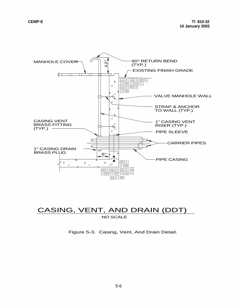
CEMP-E TI 810-3210 January 2002
5-6
MANHOLE COVER 90^ RETURN BEND(TYP.)
EXISTING FINISH GRADE
VALVE MANHOLE WALL
STRAP & ANCHORTO WALL (TYP.)
PIPE SLEEVE
CARRIER PIPES
PIPE CASING6"
NO SCALE
CASING VENTBRASS FITTING(TYP.)
12
"
1" CASING DRAINBRASS PLUG
CASING, VENT, AND DRAIN (DDT)
1" CASING VENTRISER (TYP.)
Figure 5-3. Casing, Vent, And Drain Detail.

CEMP-E TI 810-32 10 January 2002
6-1
CHAPTER 6
PREFABRICATED UNDERGROUND HEATING/COOLING DISTRIBUTION SYSTEM 6-1. GENERAL. This system is similar to Pre-engineered Underground Heat Distribution System (chapter 5) because it is factory fabricated in lengths, which are transported to the site for field assembly. However, the system is not allowed for any high temperature water (greater than 200 deg. F) or steam/condensate systems. The project designer is also responsible for more of the overall design. 6-2. SYSTEM DESIGN. a. Site information. As with all heat distribution systems, the site investigation is the responsibility of the designer. The designer will obtain soil borings, be responsible for designing all grading in the area, and investigate all utilities for possible conflicts with the system. The designer will provide detailed design plans and profiles of the distribution system routings. The design will ensure a minimum slope of 1 inch in 20 feet is maintained between valve manholes. The site information requirements are covered in detail in chapter 3 of this manual. b. Valve manholes. The designer will design all valve manholes for the system as covered in chapter 3 of this manual. As with valve manholes for the Pre-engineered Underground Heat Distribution System, manhole spacing will not exceed 500 feet and all manholes will have drainage capabilities. Also, all valves, flanges, unions, and couplings shall be located within the manholes. c. System Material Selections. Although this system is manufactured in sections in a factory, the designer will specify all materials. (1) Piping. The piping materials allowed are steel, copper tubing, reinforced thermosetting resin plastic (RTRP), or polyvinyl chloride (PVC). RTRP piping can not be routed through valve manholes with heating systems that could damage the RTRP. PVC piping can not be routed in any valve manhole with any other heating system piping due to its comparatively low temperature tolerance. (2) Casing. Allowed casing materials are PVC, polyethylene (PE), or RTRP. Because these casing materials are susceptible to damage from high temperatures, they must be installed a minimum of 15 feet from buried HTHW or steam systems to avoid plastic deformation and failures of the casing materials. (3) Insulation. Insulation type for these systems is typically polyurethane foam. Open cell type insulations, such as fiberglass, mineral wool or calcium silicate, are unacceptable for use with chilled water systems due to the tendency of condensation forming in these insulations. Insulation thickness will be specified in the guide specification. d. Expansion compensation. The designer will perform expansion compensation calculations as covered in chapter 3 of this manual. When required, based on these calculations, sizes and locations of all expansion loops and bends, and any other expansion-compensating device, will be clearly shown on the contract drawings. The designer shall provide expansion loop details.

CEMP-E TI 810-32 10 January 2002
7-1
CHAPTER 7
ABOVEGROUND HEAT DISTRIBUTION SYSTEMS 7-1. GENERAL. Aboveground distribution systems have the lowest first cost and lowest maintenance costs of any distribution system described in this manual and are completely designed by the project designer. This system is a good application for industrial areas and where water tables are high. Many installations, however, do not desire to have distribution piping above ground for aesthetic reasons. 7-2. SYSTEM DESIGN. a. Site information. The designer will determine information on the site. The designer will design all grading for the area and investigate all utilities for conflicts. The designer will provide detailed plans and profiles of the above ground distribution system routing. Although this system is aboveground, profiles will indicate system drain and vent points and also potential interferences between the concrete support piers and any buried utilities. b. Piping and fittings. All carrier piping and pipe fittings will be carbon steel and will be designed to satisfy the temperature and pressure requirements of the system. Materials will conform to the requirements of the guide specification. c. Pipe supports. The two most common types of aboveground distribution systems are low profile and high profile. (1) Low profile system. A typical low profile support is shown in figure 7-1. In this system, the distribution piping is mounted to concrete piers by means of pipe supports. Typically, the bottoms of the pipes are mounted no more than 4 feet above grade except at road crossings, which usually incorporate high profile supports. Typical anchor, free, and guided pipe supports mounted to the concrete piers are detailed in figure 7-2, figure 7-3, and figure 7-4. Spacing of supports in straight runs of piping will conform to the support spacing schedule in table 4-2. Provide extra supports, as necessary, at pipe bends and risers. Requirements for concrete piers and pipe supports are included in the guide specification. (2) High profile systems. High profile systems are routed high enough to cross roads and avoid obstructions. Typically the piping will be installed 14 to 16 feet above grade. The system presented in this manual uses 6-inch concrete-filled pipes embedded in concrete footings as detailed in figure 7-5. The pipe guides are mounted on channels at the top of the support pipe as detailed in figure 7-6. The pipe anchors are also mounted to channels and then stabilized with guy cables as shown in figure 7-7. Structural design for the structural members on these high profile supports in figure 7-6 and 7-7 are for water filled, schedule 40 steel pipes up to 10-inch nominal size. Conditions outside these constraints must be designed on a case-by-case basis. The designer for each anchor application will also size the guy cables. Spacing of supports in straight runs of piping will conform to the support spacing schedule in table 4-2. Extra supports will be added, as necessary, at pipe bends and risers. Concrete footings and high profile supports will conform to the requirements of the guide specification. c. Insulation and jacketing. All piping on aboveground systems shall be insulated and jacketed. Insulation thicknesses will be determined by insulation tables provided in the guide specification. These insulation thicknesses were developed using life cycle cost analyses. All insulation will be covered with a jacketing material in conformance with the guide specification. e. Expansion Compensation. Expansion loops and bends will be designed as described in chapter 3 of this manual. Expansion loops will be located to minimize impacts to ground level interferences such as trees and sidewalks. For horizontal expansion loops, pipe supports will be spaced less than the maximums listed in
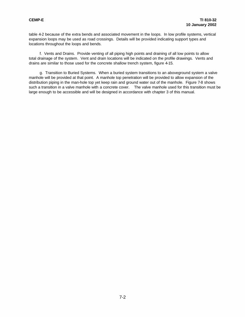
CEMP-E TI 810-32 10 January 2002
7-2
table 4-2 because of the extra bends and associated movement in the loops. In low profile systems, vertical expansion loops may be used as road crossings. Details will be provided indicating support types and locations throughout the loops and bends. f. Vents and Drains. Provide venting of all piping high points and draining of all low points to allow total drainage of the system. Vent and drain locations will be indicated on the profile drawings. Vents and drains are similar to those used for the concrete shallow trench system, figure 4-15. g. Transition to Buried Systems. When a buried system transitions to an aboveground system a valve manhole will be provided at that point. A manhole top penetration will be provided to allow expansion of the distribution piping in the man-hole top yet keep rain and ground water out of the manhole. Figure 7-8 shows such a transition in a valve manhole with a concrete cover. The valve manhole used for this transition must be large enough to be accessible and will be designed in accordance with chapter 3 of this manual.
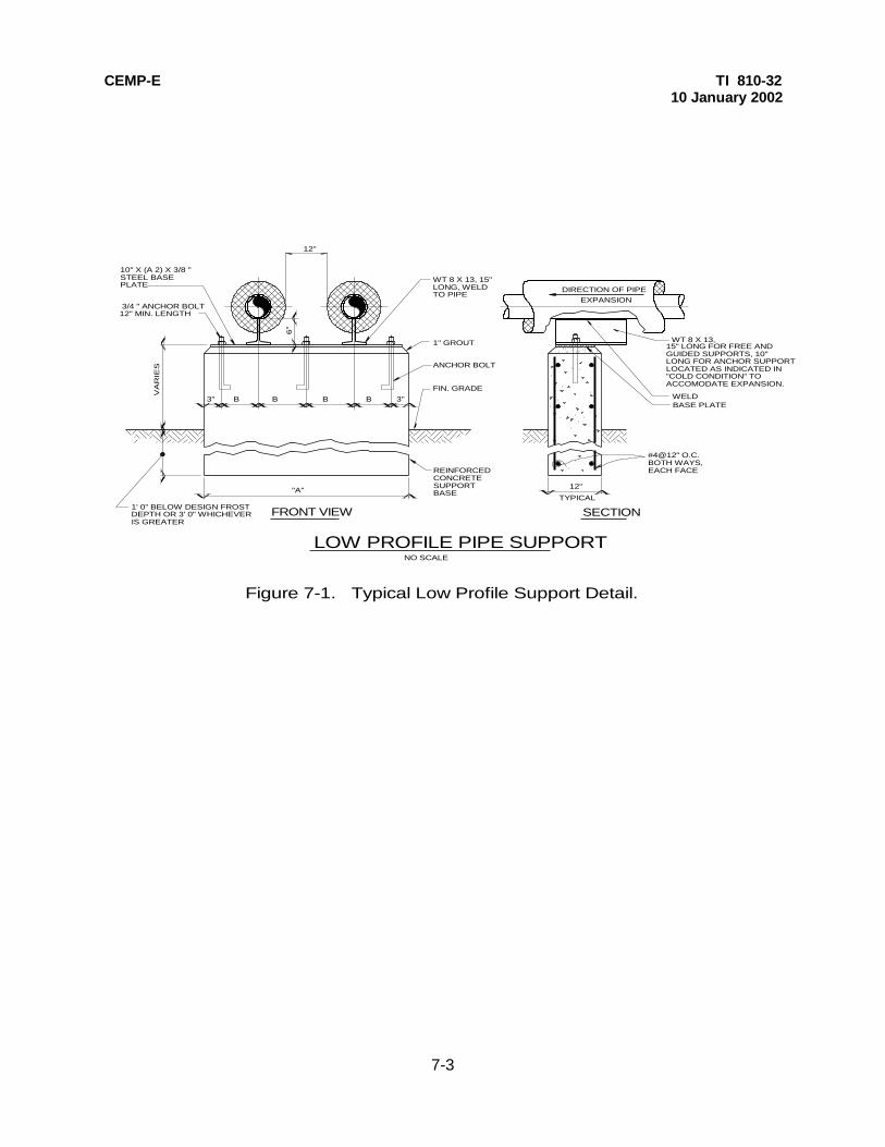
CEMP-E TI 810-3210 January 2002
7-3
DIRECTION OF PIPEEXPANSION
WELDBASE PLATE
#4@12" O.C.BOTH WAYS,EACH FACE
12"A
ATYPICAL
12"
WT 8 X 13,
LOW PROFILE PIPE SUPPORTNO SCALE
SECTIONFRONT VIEW
3"A
ABA
ABA
ABA
ABA
A3"A
A
"A"A
A
A
A
1' 0" BELOW DESIGN FROSTDEPTH OR 3' 0" WHICHEVERIS GREATER
VA
RIE
S
A
A
WT 8 X 13, 15"LONG, WELDTO PIPE
1" GROUT
ANCHOR BOLT
FIN. GRADE
6"
A
A
REINFORCEDCONCRETESUPPORTBASE
15" LONG FOR FREE AND GUIDED SUPPORTS, 10" LONG FOR ANCHOR SUPPORT LOCATED AS INDICATED IN "COLD CONDITION" TO ACCOMODATE EXPANSION.
Figure 7-1. Typical Low Profile Support Detail.
10" X (A 2) X 3/8 "STEEL BASEPLATE
3/4 " ANCHOR BOLT12" MIN. LENGTH

CEMP-E TI 810-3210 January 2002
7-4
10" WT 8X13
INSULATION
PIPE
NO SCALEANCHOR SUPPORT AS
3/16
3/16
10
10
Figure 7-2. Typical Anchor Pipe Support.
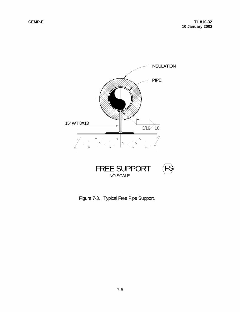
CEMP-E TI 810-3210 January 2002
7-5
INSULATION
PIPE
NO SCALE
3/16 10
FSFREE SUPPORT
15" WT 8X13
Figure 7-3. Typical Free Pipe Support.

CEMP-E TI 810-32 10 January 2002
INSULATION
PIPE
NO SCALE
3/16 1015" WT 8X13
1/4 10
GUIDED SUPPORTGS
1/4 "
7/8 "
Fig. 7-4. Typical Guided Pipe Support.
L10" LONG 1/4 "BENT P
7-6
CEMP-E TI 810-3210 January 2002
7-7
GRADE
6" STD. STEEL PIPEFILLED WITH CONCRETE
#2@ 12 TIES
4-#5
5-#4 E.W.
NO SCALE
4'-0" SQ
6"
1"
1'-6"SQ
1'
"A"*
HIGH PROFILE BASE
* "A" IS THE DESIGN FROST DEPTH, SEE TM 5-809-1 FOR FROST DEPTH
1. SITE SPECIFIC DESIGN REQ'D BASED ON LOADS AND SOIL CONDITIONS.
NOTES TO THE DESIGNER:
Figure 7-5. Typical High Profile Base Detail.

CEMP-E TI 810-3210 January 2002
7-8
3/4 " DIA. BOLT
MC 6 X 15.1
PIPE
15" MIN.35" MAX.
A
A
INSULATION SADDLE
ROLLER TYPE SUPPORT
DISTRIBUTION PIPE
RETURNDISTRIBUTIONPIPE
TOP ROLLERSUPPORTS ATRISERS
CHANNELNUT & JAM NUT
SIDE VIEW FRONT VIEW
PIPE GUIDENO SCALE
3/4 " DIA. BOLTS
1/4
1/2 " PLATES
6" DIA. PIPE COLUMN CONCRETE FILLED
10"MAX
NOTE TO THE DESIGNER:
Figure 7-6. Typical Pipe Guide Detail.
PIPE SUPPORT SHALL BE REDESIGNEDIF PIPE LARGER THAN 10" IS USED.
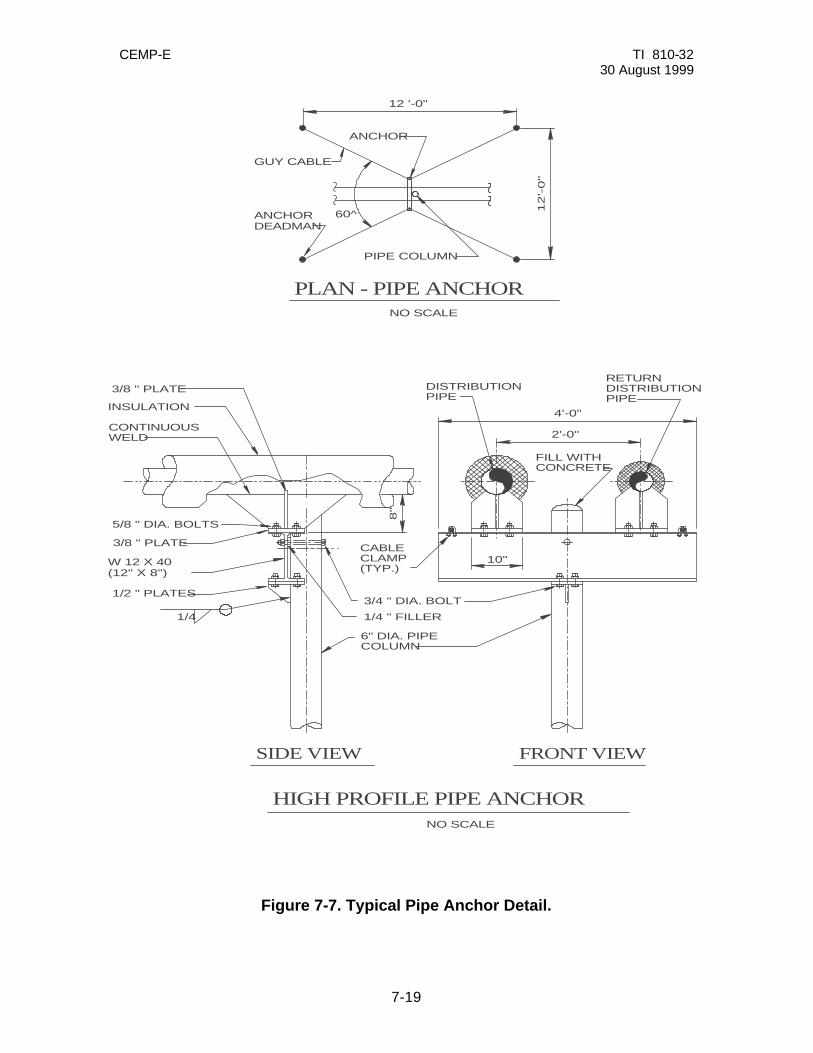
CEMP-E TI 810-32 30 August 1999
7-19
Figure 7-7. Typical Pipe Anchor Detail.
HIGH PROFILE PIPE ANCHOR
SIDE VIEW FRONT VIEW
5/8 " DIA. BOLTS
3/8 " PLATE
1/2 " PLATES
1/4
3/4 " DIA. BOLT
1/4 " FILLER
INSULATION4'-0"
2'-0"
10"
8"
NO SCALE
NO SCALE
PLAN - PIPE ANCHOR
12
'-0
"
12 '-0"
ANCHOR
PIPE COLUMN
GUY CABLE
60^
3/8 " PLATE
CONTINUOUSWELD
W 12 X 40(12" X 8")
CABLECLAMP(TYP.)
6" DIA. PIPECOLUMN
DISTRIBUTIONPIPE
RETURNDISTRIBUTIONPIPE
FILL WITHCONCRETE
ANCHORDEADMAN

CEMP-E TI 810-3210 January 2002
7-10
18"min
6"
2"2"
STEAM OR CONDENSATE LINES
INSUL. & JACKETING
TRANSITION BOOT CLAMPED TOINSULATION JACKET ABOVE &SLEEVE BELOW (SEE NOTES)
CONCRETE VAULT TOP
A=OUTSIDE PIPE DIA.B=OUTSIDE INSUL.&JACKET DIA.*C=MIN. SLEEVE INSIDE DIA.=B+4* SEE SPEC. FOR INSULATION THICKNESS
A
B
C
NO SCALE
TRANSITION BOOT (LINER) SHALL BE:- 25 MIL THICKNESS (MIN)- E.P.D.M. TYPE MEMBRANE- COMPATIBLE AT HIGH (220^ F) AND LOW (-40^ F) TEMPERATURES- RESISTANT TO ULTRAVIOLET LIGHT DEGRADATION
LINER SEAM SHALL PROVIDE 2" MINIMUM OF OVERLAP.USE SOLVENT CEMENT AS APPROVED BY LINER MANUFACTURER.
1.
2.
NOTES:
VALVE MANHOLE TOP PENETRATION
SLEEVE GROUTED INTO MANHOLETOP (BEVEL EXPOSED END OFSLEEVE)
Figure 7-8. Valve Manhole Top Penetration Detail.
STAINLESS STEEL BAND (TYPE 201STAINLESS STEEL, 1/2 " WIDE, 0.030"THICK) WITH CORROSION RESISTANTBUCKLES

CEMP-E TI 810-32 10 January 2002
8-1
CHAPTER 8
SPECIAL CONSIDERATIONS
8-1. GENERAL. Although it is impractical to cover all special considerations, which arise in heating and cooling distribution designs, this chapter presents typical design problems and solutions associated with steam, high temperature hot water, low temperature hot water and chilled water systems. 8-2. STEAM SYSTEMS. a. Trap Selection. Steam traps are used to separate the condensate and non-condensable gases from the steam. Many types of traps are used on drip legs for steam distribution systems. Those trap types include float and thermostatic (F&T), inverted bucket, thermostatic and thermodynamic (disc). However, for buried heat distribution drip leg applications, inverted bucket or thermostatic (bimetallic type) should be the trap types selected. For drip leg applications where freezing is a consideration, thermodynamic type (installed vertically) or bimetallic thermostatic type should be selected. b. Trap Sizing and Location. Trap sizing is important for obtaining an efficient steam distribution system. Condensation in the steam line is caused by heat loss from the steam line. Trap life will be shortened, function affected and excessive energy will be wasted if traps are oversized to handle the higher initial startup condensate flows. Therefore, the traps should be sized for the condensate load seen during the distribution system normal operation. Because the traps are not sized for startup loadings, the bypass must be opened at startup to allow condensate to pass until the steam line has reached normal operating temperatures (see figure 8-1). The designer will calculate heat loss and condensate flow for that particular design using the methods presented in appendix D for determining condensate loads during normal operation. It is critical that the designer calculate trap capacity using the Appendix D method for each trap station in the design to ensure proper steam system operation. In addition to trap capacity, steam trap type, differential pressures, and inlet pressure must always be provided on the contract documents. Do not locate steam drip legs, with associated traps, more than 500 feet apart. c. Drip Leg Sizing. Drip legs, installed vertically down from the steam pipe, are used to collect condensate. Design all steam lines to slope at 1 inch in 20 feet minimum toward these drip legs. It is preferable to slope the steam lines in the direction of steam flow whenever possible. The steam trap line and bypass line are connected to the drip leg as indicated in figure 8-1. The drip leg will be the same nominal pipe size as the main line (up to a 12-inch line) and will provide a storage capacity equal to 50% of the startup condensate load (no safety factor, one-half of an hour duration) for line sizes 4 inches in diameter and larger and 25% of the startup condensate load (no safety factor, one-half of an hour duration) for line sizes less than 4 inches. In no case will the drip leg be less than 18 inches in length or larger than 12 inches in diameter for all steam line sizes. The designer will calculate startup loads for drip leg sizing using the methods presented in appendix D. d. Trap Station Layout. All trap stations will be piped as indicated in figure 8-1, as a minimum. Valve and strainer sizes will match the line sizes on which they are installed. Pipe lines to and from the steam trap will be sized based on calculated trap capacity but will be no less than 3/4-inch nominal size (line size "A" on figure 8-1). If reducing fittings are needed at the trap inlet and outlet, eccentric reducers must be used. The bypass line will be sized to accommodate warm-up condensate loads. For steam systems with an operating pressure of 150 psig or less and pipe sizes 12 inches or less, provide a ¾-inch bypass line. If the condensate return main is a low pressure or gravity flow type, the trap discharge line will be routed through an accumulator, as indicated in figure 8-2. The accumulator will lower the trap discharge temperature and minimize flashing when the condensate is introduced into sloped condensate lines which are routed to receiver/pump sets located in valve manholes. The pumps push the condensate back to the central plant in a separate pressurized condensate line. See figure 8-3 for a duplex condensate pump set connection detail.

CEMP-E TI 810-32 10 January 2002
8-2
This type of condensate return system is referred to as a "three pipe" or a "pumped return" system. If the steam pressure is sufficiently high, it may be used to force the condensate through the condensate return system to the central plant as shown in figure 8-1. No accumulator is required for this type system, which is referred to as a "two pipe" system. Sizing of the lines for both of these systems is presented later in this chapter. e. Condensate Cooling System. Fiberglass reinforced plastic (FRP) piping is usually allowed for most condensate return systems. Since internal corrosion is a frequent problem in steel condensate lines, FRP eliminates this problem. However, the FRP materials cannot withstand as high of pressures or temperatures as steel and often fail when exposed to these conditions. A common temperature in an FRP distribution piping system where damage will occur is 250 deg. F. Condensate temperatures may exceed 250 deg. F. at the outlet of steam drip leg traps on steam systems that have pressures greater than 15 psig. In order to use FRP condensate lines in this case, a condensate cooling system will be employed, as detailed in figure 8-4. In this system, the high temperature condensate is discharged into a cooling tank where it blends with the system condensate. The blended condensate is then routed to the condensate main. Note that the detail shows the FRP (or non-metallic) pipe transitioning to steel inside the valve manhole to avoid burying the transition point. Also, note that nonmetallic piping will not be allowed in a manhole with high temperature hot water or high pressure steam systems due to the potential for this pipe being exposed to damaging temperatures within the manhole if the manhole floods or the carrier pipe on the heating system leaks. f. Non-metallic Pipe Anchors in Valve Manholes. If anchoring of a non-metallic piping system is required at the valve manhole wall to comply with the distribution system stress analysis, a typical method is as detailed in figure 8-5. If the system is to be anchored at both of the valve manhole wall penetrations, provide adequate piping bends in the manhole to accommodate the expansion between the two anchors. Steel straps and bolts will be sized to accommodate the axial force of that particular piping layout. These sizes will be entered on the detail. Also, valve manhole sizes must be large enough to accommodate the anchors and still allow for maintenance access. g. Pipe Sizing. Pipe sizing is critical to proper operation of both the steam and the condensate return systems. (1) Steam. There are several methods to size steam lines. One of the quickest and most popular methods is using pressure drop versus flow rate charts, which provide steam velocities based on the required flow and pressure drops. The American Society of Heating, Refrigeration, and Air Conditioning Engineers (ASHRAE) Fundamentals Handbook, Chapter "Pipe Sizing", is a good source for these steam sizing tables. Recommended velocities for various system pressure ranges are: 0 - 10 psig, saturated - 1,000 to 4,000 fpm 10 - 50 psig, saturated - 4,000 to 8,000 fpm 50 - 150 psig, saturated - 8,000 to 12,000 fpm In addition, ensure the total pressure drop in the system will not be excessive. Steam pressure must be high enough at the end users to meet all special process requirements. (2) Condensate. As described previously in this chapter, there are basically two types of condensate return systems used on central heating systems: the two pipe system (which uses steam pressure to force condensate back to the plant) and the three pipe, or pumped return, system. When sizing lines for these condensate return systems, table 8-1 will be used for guidance. h. Steam System Material Selection. (1) Valves. For high-pressure steam systems (125 psig or greater), valves will be 300-pound class and
CEMP-E TI 810-32 10 January 2002
8-3
will have welded ends. Steam and condensate valves at lower pressures will be 150-pound class with welded ends. Valves on trap stations, including the bypass valve, will be 150-pound class with threaded ends. Shutoff valves will be gate type. (2) Fittings. All fittings in the steam distribution system, except as discussed for valves, will be welded except at equipment, traps, strainers, and items which require frequent removal. These items will be threaded or flanged. (3) Piping. Steam and condensate piping will usually be carbon steel conforming to ASTM A 53, Grade B, Type E or S. Steam piping will be schedule 40. Condensate lines will be schedule 80 as will all welded piping less than 1-1/2 inches. Condensate lines in a pre-engineered underground heat distribution system may be FRP as discussed in chapter 5. i. Field Joints. Radiographic examination of all carrier pipe field joints is required. 8-3. HTHW SYSTEMS. a. Pipe Sizing. Sizing lines for HTHW systems is similar to any water system, except at high temperatures water becomes less dense and less viscous, and, therefore, the mass flow rate of the system must be calculated considering the lower density (usually temperatures are around 400 deg. F for HTHW). m = q x 60 min/hr x 0.1335 ft 3 /gal x ? where q = system flow in gal/min m = mass flow rate in lbm/hr ? = density of water at maximum system temperature in lbM/ft3
Pressure drop versus flow charts may be used to determine line size, such as the chart included in appendix B. This chart takes into account the characteristics of higher temperature water systems. Recommended velocities for various HTHW flows are as follows: Up to 10,000 lbm/hr - 1 to 2 feet/sec 10,000 to 30,000 lbm/hr - 2 to 3 feet/sec 30,000 to 200,000 lbm/hr - 3 to 5 feet/sec 200,000 lbm/hr on up - (use velocity to accommodate 0.50 psi/100 ft., maximum) b. HTHW System Material Selection (1) Valves. All valves on HTHW systems will be 300-pound class with welded ends. Shutoff (isolation) valves will be gate type. Valve packings must be capable of handling the pressures and temperatures associated with HTHW systems. (2) Fittings. All fittings on HTHW systems will be welded. The only exceptions will be specialty equipment such as dielectric flanges used to isolate the piping system from a cathodically protected system. (3) Piping. HTHW piping will be carbon steel conforming to ASTM A53, Grade B, Type E or S. All piping will be schedule 40 except for welded pipe less than 1-1/2 inches, which will be schedule 80.

CEMP-E TI 810-32 10 January 2002
8-4
8-4. LTHW and CW systems. a. Pipe Sizing. The most efficient method of determining pipe size for LTHW and CW systems is to use head loss vs. flow rate charts such as those found in ASHRAE Fundamentals, Chapter "Pipe Sizing". These tables are based on 60 deg. F water so for chilled water pipe sizing there is little error introduced using these charts. For LTHW systems, the use of the charts does introduce some error. However, the error is on the conservative side (the charts overstate the pressure drop of LTHW). b. LTHW and CW Material Selection. (1) Valves. Typically, valves on either LTHW or CW systems will be 150-pound class and will be located in the valve manholes. Ball valves provide a good means for line isolation. Although nonmetallic valves are sometimes allowed for these systems, metallic valves should be used for durability. (2) Piping. The most common piping materials used for LTHW and CW systems are steel, copper tubing, reinforced thermosetting resin pipe (fiber- glass) and, for CW only, polyvinyl chloride and polyethylene. However, do not include nonmetallic piping in the same valve manholes with HTHW and steam systems. Chilled water lines using PVC piping must be installed in separate valve manholes since PVC can be thermally damaged at relatively low temperatures. Outside the valve manholes, a separation of 15 feet (minimum) must be maintained between pre-engineered underground HTHW and steam systems and PVC encased, prefabricated underground heating/cooling distribution systems to avoid thermal degradation of the PVC.

CEMP-E TI 810-3210 January 2002
8-6
HIGH OR MEDIUMPRESSURE CONDENSATERETURN LINE
STEAM MAIN
THREADEDCAP
ISOLATION GATEVALVE (TYPICAL)
DRIP LEG
BYPASSBALL VALVE
"A"
3/8 " THREAD-O-LETTEST CONDITION
STEAMTRAP
STRAINER WITHBLOWOFF VALVE
1" DRAINGATE VALVE
CHECKVALVE
3/4 "
TRAP STATION LAYOUT ISOMETRICNO SCALE
1"
1" DRAINGATE VALVE
REDUCER ,IF NEEDED(TYPICAL)
NOTE TO THE DESIGNER:
* SEE NOTE TO THE DESIGNER
* HIGH PRESSURE CONDENSATE DISCHARGEFROM THE TRAP WILL NOT BE DIRECTLYROUTED TO A GRAVITY OR LOW PRESSURECONDENSATE SYSTEM. IN THIS INSTANCE,A 3/4 " LINE WILL BE ROUTED TO ANACCUMULATOR BEFORE BEING ROUTED TO ACONDENSATE PUMP (SEE FIGURE 8-2).
Figure 8-1. Trap Station Layout Schematic.

CEMP-E TI 810-32 10 January 2002
8-7
3/4 " GATE VALVE
8" WELDING CAP
8" SCH. 40 PIPE
FROM TRAP
REINFORCING PLATE
TO CONDENSATE RETURN LINE
3/4 " GATE VALVE
4"
10"
1'-6"
3'-0"
2"
ACCUMULATOR
12" 6" 3" 0 1' 9"
1 2 SCALE .
. INCH = 1 FOOT 1
0 12" 6" 1' SCALE .
. INCH = 1 FOOT 1
BRACKET
4"
INSTALL 1/2 " ANCHOR BOLTS, 2 REQUIRED
Fig. 8-2. Accumulator Detail.
MANHOLEWALL
SEE
BRACKET
DETAIL

CEMP-E TI 810-32 10 January 2002
Fig. 8-3. Duplex Condensate Pump Set Connection Detail.
NO SCALE
DUPLEX CONDENSATE PUMPSET CONNECTION DETAIL
CHECK VALVE
CD
CD
BALL DRAINVALVE
CONDENSATEPUMP DISCHARGE
VENT THRU VALVEMANHOLE TOP
CONDENSATE IN
PUMP(TYP. OF 2)
6" CONC. PADCHECK VALVE
8-8

CEMP-E TI 810-32 10 January 2002
18"
MIN
. F
RO
M F
LR
.
DIF
FU
SE
R: 1
0 IN
CH
ES
OF
1
/2 "
PIP
E W
ITH
MIN
IMU
M O
F 1
8 -
1
/8 "
DIA
. H
OL
ES
, C
AP
PE
D A
T E
ND
CO
OL
ING
TA
NK
: 1
8 IN
CH
ES
LO
NG
, 8
"D
IA. S
CH
ED
UL
E 8
0 P
IPE
WIT
H 8
"D
IA. W
EL
D C
AP
SA
DJU
ST
AB
LE
AN
GL
E T
HE
RM
OM
ET
ER
WIT
H 3
0^F
TO
30
0^
F R
AN
GE
AN
D A
3
/4 "
NP
T B
RA
SS
WE
LL
3/4
" T
EM
PE
RA
TU
RE
RE
LIE
F V
AL
VE
SE
T T
O
OP
EN
AT
25
0^
1/2
" D
RA
IN
UN
ION
(T
YP
.)
1"
MIN
. D
IA.
0 -
15
0 P
SIG
GA
GE
WIT
H C
OC
K
FR
OM
ST
EA
MM
AIN
TR
AP
3/4
"
VA
UL
T W
AL
L
3/4
" D
ISC
HA
RG
EA
BO
VE
GR
AD
E
NO SCALE
18" MIN.
GA
TE
VA
LV
E(T
YP
.)
CONDENSATE COOLING SYSTEM
ST
EA
M T
RA
P C
AP
AC
ITY
LIM
ITA
TIO
NS
50
10
01
50
20
03
00
40
0
MA
XIM
UM
TR
AP
C
AP
AC
ITY
(L
BS
./H
R.)
SY
ST
EM
PR
ES
SU
RE
(PS
IG)
25
03
80
50
06
25
79
09
60
PU
MP
ED
IN
SU
LA
TE
D R
ET
UR
N C
ON
DE
NS
AT
EM
AIN
(S
CH
. 8
0 S
TE
EL
)
6"IN
SU
LA
TE
D N
ON
-M
ET
AL
LIC
PIP
E (
TY
P)
Fig. 8-4.
Condensate Cooling System for Non-metallic Pipe Detail.
NO
N-M
ET
AL
LIC
TO
S
TE
EL
CO
UP
LIN
G
OR
FL
AN
GE
8-9
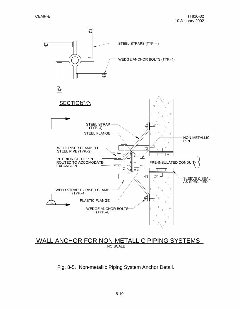
CEMP-E TI 810-32 10 January 2002
SLEEVE & SEALAS SPECIFIED
NO SCALE
PLASTIC FLANGE
STEEL FLANGE
STEEL STRAPS (TYP.-4)
WEDGE ANCHOR BOLTS (TYP.-4)
WEDGE ANCHOR BOLTS (TYP.-4)
WELD STRAP TO RISER CLAMP (TYP.-4)
WELD RISER CLAMP TOSTEEL PIPE (TYP.-2)
STEEL STRAP (TYP.-4)
A
ASECTION
INTERIOR STEEL PIPEROUTED TO ACCOMODATEEXPANSION
WALL ANCHOR FOR NON-METALLIC PIPING SYSTEMS
Fig. 8-5. Non-metallic Piping System Anchor Detail.
NON-METALLICPIPE
PRE-INSULATED CONDUIT
8-10

CEMP-E TI 810-32 10 January 2002
8-10
Table 8-1. Pipe sizing guidelines for condensate return systems.
TWO-PIPE SYSTEM SIZING GUIDELINES _____________________________________________________________________________
?? DETERMINE CONDENSATE LINE PRESSURE (AS OBSERVED FROM ON-SITE
PRESSURE GAGES). ?? DETERMINE CONDENSATE LOAD (lbm/hr) FROM CENTRAL PLANT LOGS AND OTHER
INPUT. ?? ASSUME CONDENSATE AT TRAP DISCHARGE IS A COMBINATION OF CONDENSATE
AND FLASH STEAM. ?? SIZE LINE TO ACCOMMODATE 5,000 ft/min STEAM AND CONDENSATE MIXTURE
VELOCITY AND TO ENSURE MIXTURE PRESSURE IS HIGH ENOUGH TO OVERCOME LINE LOSSES.
THREE-PIPE SYSTEM SIZING GUIDELINES ____________________________________________________________________________________ GRAVITY LINE ?? SLOPE AT 1 inch/20 feet (MINIMUM) TOWARD RECEIVER. ?? TOTAL PRESSURE DROP LESS THAN 0.25 psi. ?? LINE SIZE WILL BE TWO (2) INCHES. PUMPED LINE ?? SIZE PUMPS TO MOVE CONDENSATE TO THE CENTRAL PLANT AT THE REQUIRED
HEAD AT 200 deg. F.

CEMP-E TI 810-32 10 January 2002
A-1
APPENDIX A
REFERENCES Government Publications Department of the Army TM 5-802-1 Economic Studies for Military Construction Design-Applications TM 5-809-1 Load Assumption for Buildings Non-government Publications American National Standards Institute (ANSI) 1430 Broadway, New York, NY 10018 H35.1 (1990) Alloy and Temper Design System for Aluminum American Society for Testing and Materials (ASTM) 1916 Race Street, Philadelphia, PA 19103 A 36 (1991) Structural Steel A 53 (1988a) Pipe, Steel, Black and Hot Dipped, Zinc Coated, Welded and Seamless A 123 (1989a) Zinc (Hot-Dip Galvanized) Coatings on Iron and Steel Products A 615 (1990) Deformed and Plain Billet-Steel Bars for Concrete Reinforcement American Society of Heating, Refrigerating, and Air Conditioning Engineers, Inc.,
1791 Tullie Circle, N.E., Atlanta, GA 30329 ASHRAE Handbook Fundamentals ASHRAE Handbook HVAC Systems and Applications American Society of Mechanical Engineers (ASME),
22 Law Drive, Box 2300, Fairfield, NJ 07007-2300 B31.1 (1989) Power Piping Canadian Society of Civil Engineers,
Montreal, Quebec, Canada (1986) Cold Climate Utilities Manual
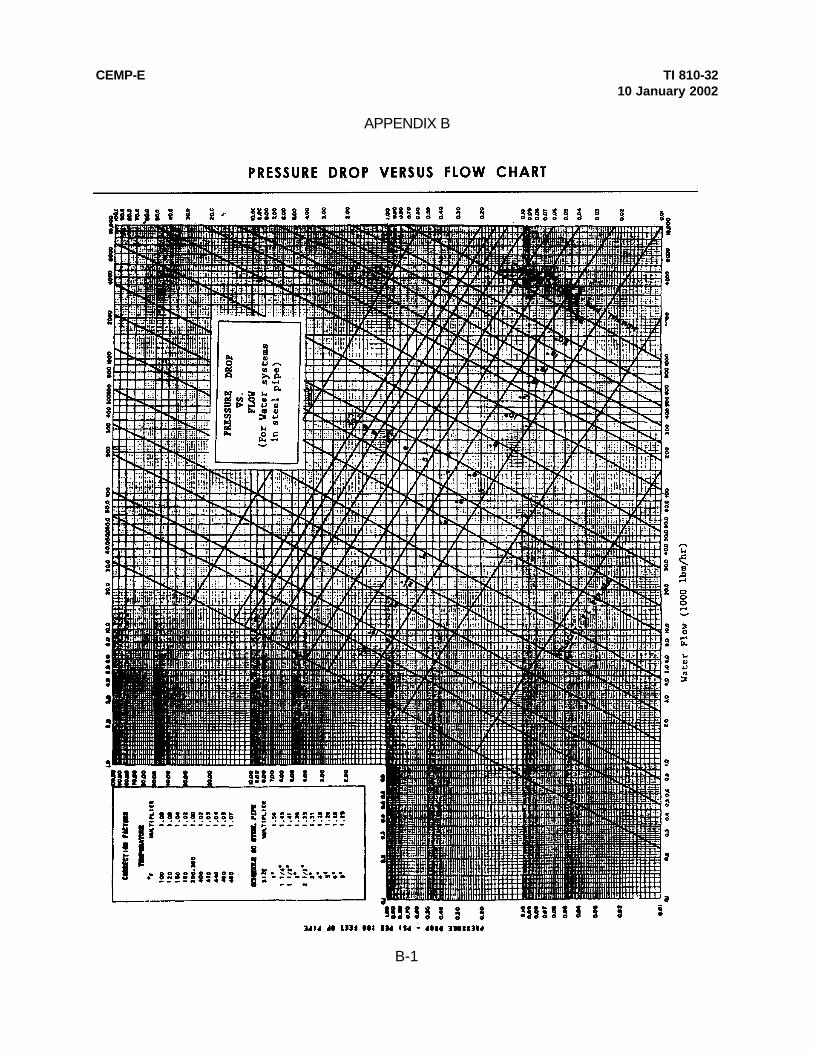
CEMP-E TI 810-32 10 January 2002
APPENDIX B
B-1

CEMP-E TI 810-32 10 January 2002
C-1
APPENDIX C
CONDENSATION LOAD CALCULATIONS (NORMAL) Step #1 Determine the heat loss per foot of line. Q = 2? (Tst - Tout)/(ln(ro/ri )/kp + ln(rio /ro) /kin + 1/3r io) Assumptions. This equation models an insulated pipe surrounded by air. The convective resistance between the insulation and the outside of the pipe is assumed to be negligible. Also, the convective heat transfer coefficient outside of the insulation is assumed to be 3 BTU/hr-ft2 deg. F. Step #2 Determine the flow of condensate from the heat loss calculated in step #1. m = Q/(hst - hcon) Step #3 Multiply the flow rate per foot, calculated in step #2, by the total number of feet of steam line that slopes toward the trap in question. The result is the minimum flow capacity of the trap. where: Q = heat loss per foot of pipe; Btu/hr-ft Tst = temperature of steam; deg. F Tout = temperature of ambient conditions; deg. F ro = outside pipe radius; feet ri = inside pipe radius; feet rio = outside insulation radius; feet kp = thermal conductivity of pipe; Btu/hr-ft- deg. F; (26 Btu/hr-ft-deg. F for steel) kin = thermal conductivity of insulation; Btu/hr-ft- deg. F * (see table below) m = mass flow rate of condensate; lbm/hr-ft hst = enthalpy of saturated steam; Btu/lbm hcon = enthalpy of condensate; Btu/lbm ------------------------
\1\ *K-value (Btu/hr-ft-deg. F /1/ Insulation Type 400 deg. F 300 deg. F 200 deg. F Mineral Fiber 0.034 0.029 0.024 Calcium Silicate 0.042 0.038 0.035

CEMP-E TI 810-32 10 January 2002
D-1
APPENDIX D
CONDENSATION LOAD CALCULATIONS (STARTUP) Step #1 Determine the heat loss per foot of line. The startup load can be calculated by determining the amount of heat that is required to heat the steam pipe from an ambient temperature to the saturation temperature of the steam the pipe is to carry. This is done by using the following equation: Q = (vp * cp * ?p (tst - Tout))/t; Btu/ft where: vp = ? (ro
2- r2); in ft3/ft Step #2 Determine the pounds of condensate per foot from the heat loss calculated in step #1. m = Q/(hst - hcon); lbm/ft Step #3 Multiply the condensate per foot, calculated in step #2, by the total number of feet of steam line that slopes toward the drip leg in question. Then convert the total pounds of condensate to gallons assuming 200 F condensate: Total Condensate Volume (gallons)=(m*L)*7.49 gallons/ft3 60.1 lbm/ft3 where: Q = heat loss per foot of pipe; Btu/hr-ft Tst = temperature of steam; deg. F Tout = temperature of ambient conditions; deg. F ro = outside pipe radius; feet ri = inside pipe radius; feet m = mass flow rate of condensate; lbm/hr-ft hst = enthalpy of saturated steam; Btu/lbm hcon = enthalpy of condensate; Btu/lbm cp = specific heat of pipe (steel); (0.10 to 0.11) Btu/lbm/degrees F ? p = density of pipe (steel); (489) lbm/ft3 t = length of time for startup; hrs (typically 0.5 hrs.) L = total length of pipe draining to drip; ft vp = volume of pipe material per foot; ft3/ft