UNIDIRECTIONAL Knife Gate Valve - Berkon Proses · ‐ Mechanically‐welded body. ... This knife...
17
KNIFE GATE VALVES C SERIES C.M.O. Amategui Aldea 142, 20400 Txarama‐Tolosa (SPAIN) TEC‐A.EN08 Tel. Nacional: 902.40.80.50 Fax: 902.40.80.51 / Tel. Internacional: 34.943.67.33.99 Fax: 34.943.67.24.40 [email protected] http://www.cmo.es Page 1 12/04/2016 ‐ Unidirectional knife gate valve. ‐ Mechanically‐welded body. ‐ Various seat and packing materials available. ‐ Face‐to‐face dimension in accordance with C.M.O. standard, it is also possible to build the product according to the customer’s needs. General Applications: ‐ This knife gate valve is suitable for solids, it is also recommended in gravity discharge applications for fluids with high solid content. Designed for a wide range of applications such as: ‐ Mining. ‐ Bulk transport. ‐ Chemical plants. ‐ Food Industry. Sizes: ‐ From 125x125 to 1400x1400. ‐ Also available in rectangular designs. ‐ Larger sizes on request. Working Pressure ‐ Standard: 0,6 Kg/cm 2 . ‐ For larger pressures, consult C.M.O. Standard Flanges: ‐ The connecting flanges are in accordance with C.M.O. standard. ‐ Special connecting flanges can be manufactured on request. ‐ The connecting flange and the face‐to‐face dimension can be adapted to the customer’s needs. Directives: ‐ Machinery Directive: DIR 2006/42/EC (MACHINERY). ‐ Pressure Equipment Directive: DIR 97/23/EC (PED) ART.3, P.3. ‐ Potential Explosive Atmospheres Directive: DIR 94/9/EC (ATEX) CAT.2 ZONE 1 and 21 GD For further information on categories and zones please contact the C.M.O. Technical‐Commercial Department. Quality Dossier: ‐ The watertight integrity of the seat area is measured with gauges. ‐ Material and testing certificates can be supplied on request. UNIDIRECTIONAL Knife Gate Valve Fig. 1
Transcript of UNIDIRECTIONAL Knife Gate Valve - Berkon Proses · ‐ Mechanically‐welded body. ... This knife...

K N I F E G A T E V A L V E S C S E R I E S
C.M.O.
Amategui Aldea 142, 20400 Txarama‐Tolosa (SPAIN) TEC‐A.EN08
Tel. Nacional: 902.40.80.50 Fax: 902.40.80.51 / Tel. Internacional: 34.943.67.33.99 Fax: [email protected] http://www.cmo.esPage1
12/04/2016
‐ Unidirectional knife gate valve.
‐ Mechanically‐welded body.
‐ Various seat and packing materials available.
‐ Face‐to‐face dimension in accordance with C.M.O. standard, it is also possible to build the product
according to the customer’s needs.
General Applications: ‐ This knife gate valve is suitable for solids, it is also recommended in
gravity discharge applications for fluids with high solid content.
Designed for a wide range of applications such as:
‐ Mining. ‐ Bulk transport. ‐ Chemical plants. ‐ Food Industry.
Sizes: ‐ From 125x125 to 1400x1400.
‐ Also available in rectangular designs.
‐ Larger sizes on request.
Working Pressure
‐ Standard: 0,6 Kg/cm2.
‐ For larger pressures, consult C.M.O.
Standard Flanges: ‐ The connecting flanges are in accordance with C.M.O. standard.
‐ Special connecting flanges can be manufactured on request.
‐ The connecting flange and the face‐to‐face dimension can be
adapted to the customer’s needs.
Directives:
‐ Machinery Directive: DIR 2006/42/EC (MACHINERY).
‐ Pressure Equipment Directive: DIR 97/23/EC (PED) ART.3, P.3.
‐ Potential Explosive Atmospheres Directive: DIR 94/9/EC (ATEX) CAT.2 ZONE 1 and 21 GD For further
information on categories and zones please contact the C.M.O. Technical‐Commercial Department.
Quality Dossier:
‐ The watertight integrity of the seat area is measured with gauges.
‐ Material and testing certificates can be supplied on request.
UNIDIRECTIONAL Knife Gate Valve
Fig. 1
K N I F E G A T E V A L V E S C S E R I E S
C.M.O.
Amategui Aldea 142, 20400 Txarama‐Tolosa (SPAIN) TEC‐A.EN08
Tel. Nacional: 902.40.80.50 Fax: 902.40.80.51 / Tel. Internacional: 34.943.67.33.99 Fax: [email protected] http://www.cmo.esPage2
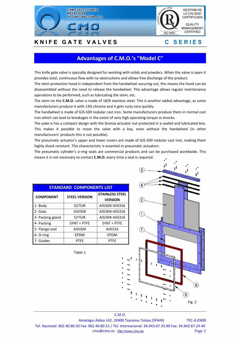
This knife gate valve is specially designed for working with solids and powders. When the valve is open it
provides total, continuous flow with no obstructions and allows free discharge of the product. The stem protection hood is independent from the handwheel securing nut, this means the hood can be
disassembled without the need to release the handwheel. This advantage allows regular maintenance
operations to be performed, such as lubricating the stem, etc. The stem on the C.M.O. valve is made of 18/8 stainless steel. This is another added advantage, as some
manufacturers produce it with 13% chrome and it gets rusty very quickly.
The handwheel is made of GJS‐500 nodular cast iron. Some manufacturers produce them in normal cast
iron which can lead to breakages in the event of very high operating torque or knocks. The yoke is has a compact design with the bronze actuator nut protected in a sealed and lubricated box.
This makes it possible to move the valve with a key, even without the handwheel (in other
manufacturers’ products this is not possible). The pneumatic actuator’s upper and lower covers are made of GJS‐500 nodular cast iron, making them
highly shock resistant. This characteristic is essential in pneumatic actuators. The pneumatic cylinder’s o‐ring seals are commercial products and can be purchased worldwide. This
means it is not necessary to contact C.M.O. every time a seal is required.
STANDARD COMPONENTS LIST
COMPONENT STEEL VERSION STAINLESS STEEL
VERSION
1‐ Body S275JR AISI304‐AISI316
2‐ Gate AISI304 AISI304‐AISI316
3‐ Packing gland S275JR AISI304‐AISI316
4‐ Packing SYNT + PTFE SYNT + PTFE
5‐ Flange seal AISI304 AISI316
6‐ O‐ring EPDM EPDM
7‐ Guides PTFE PTFE
Advantages of C.M.O.’s "Model C"
Fig. 2
Table 1

K N I F E G A T E V A L V E S C S E R I E S
C.M.O.
Amategui Aldea 142, 20400 Txarama‐Tolosa (SPAIN) TEC‐A.EN08
Tel. Nacional: 902.40.80.50 Fax: 902.40.80.51 / Tel. Internacional: 34.943.67.33.99 Fax: [email protected] http://www.cmo.esPage3
1‐ BODY One‐piece mechanically welded body, with guides to support the gate and slides. The bodies can be square or rectangular. C.M.O. has a standard design as regards the drilling of the flanges and the face‐to‐face dimension, but the design of the valve can be adjusted to the dimensions required by the customer. The standard manufacturing materials are S275JR carbon steel and AISI304 or AISI316 stainless steel. Other stainless steel alloys such as AISI316Ti, Duplex, 254SMO, Uranus B6, etc. are available on request. As a rule, iron or carbon steel valves are painted with an anti‐corrosive protection of 80 microns of EPOXY (colour RAL 5015), although other types of anti‐corrosive protections are also available. 2‐ GATE The standard manufacturing materials are AISI304 stainless steel in valves with carbon steel body and
AISI316 stainless steel in valves with AISI316 body. Other materials or combinations can be supplied on
request. The gate is polished on both sides to provide a smooth contact surface with the resilient seat. At the
same time, the sharp edges on the gate are rounded to prevent the seal from being cut. Different
degrees of polishing, anti‐abrasion treatments and modifications are available to adapt the valves to the
customer’s requirements. 3‐ SEAT The following four types of seats are available according to the working application: ‐ Seat 1: Metal / metal seat. This type of seat does not include any kind of resilient seat and the estimated leakage (considering water as the test fluid) is 1.5% of the pipe flow.
‐ Seat 2: Standard soft‐seated valve. This type of seat includes a resilient seat which is fixed to the inside of the body via a stainless steel retaining flange.
‐ Seat 3 and 4: The same as seats 1, and 2 but including a deflector. The deflector is a rectangular cone‐shaped piece located at the valve’s entrance with two functions (to protect the valve from abrasion and guide the flow to the centre of the valve’s flow). Various materials are available for the deflector (AISI304, AISI316, etc.).
The possible materials for the watertight seal are as follows:
‐ EPDM: This is the standard resilient seat fitted on C.M.O. valves. It can be used in many applications,
however, it is generally used for water and products diluted in water at temperatures no higher than
90°C*. It can also be used with abrasive products and it provides the valve with 100% watertight
integrity.
‐ NITRILE: It is used in fluids containing fats or oils at temperatures no higher than 90°C*. It provides the
valve with 100% watertight integrity. ‐ VITON: Suitable for corrosive applications and continuous high temperatures of up to 190°C and peaks
of 210°C. It provides the valve with 100% watertight integrity. ‐ SILICONE: Mainly used in the food industry and for pharmaceutical products with temperatures no
higher than 200°C. It provides the valve with 100% watertight integrity. ‐ PTFE: Suitable for corrosive applications and pH between 2 and 12. Does not provide the valve with
100% watertight integrity. Estimated leakage: 0.5% of the tube flow.
fig. 3

K N I F E G A T E V A L V E S C S E R I E S
C.M.O.
Amategui Aldea 142, 20400 Txarama‐Tolosa (SPAIN) TEC‐A.EN08
Tel. Nacional: 902.40.80.50 Fax: 902.40.80.51 / Tel. Internacional: 34.943.67.33.99 Fax: [email protected] http://www.cmo.esPage4
Note: In some applications other types of resilient materials are used, such as hypalon, butile or
natural rubber. Please contact us if you require one of these materials.
4‐ PACKING C.M.O.’s standard packing is composed of a three packing
strips which provide watertight integrity between the body
and the gate, preventing any type of leakage to the
atmosphere. It is located in an easily accessible place and can
be replaced without dismantling the valve from the pipeline. Below we indicate various types of packing available according
to the application to be given to the valve:
GREASED COTTON (Recommended for hydraulic services): This packing is composed of braided cotton
fibres soaked in grease both inside and out. It is for general use in hydraulic applications in both pumps
and valves. DRY COTTON: This packing is composed of cotton fibres. It is for general use in hydraulic applications
with solids. COTTON + PTFE: This packing is composed of braided cotton fibres soaked in PTFE both inside and out. It
is for general use in hydraulic applications in both pumps and valves. SYNTHETIC + PTFE: This packing is composed of braided synthetic fibres soaked in PTFE both inside and
out. It is for general use in hydraulic applications in both pumps and valves and in all types of fluids,
especially with the corrosive ones, including concentrated and oxidising oils. It is also used in liquids with
solid particles in suspension. GRAPHITE: This packing is composed of high‐purity graphite fibres. A diagonal braiding system is used
and it is impregnated with graphite and lubricant which helps to reduce porosity and improve operation. It has a wide range of applications as graphite is resistant to steam, water, oils, solvents, alkali and most
acids. CERAMIC FIBRE: This packing is composed of ceramic material fibres. Its main applications are with air
or gas at high temperatures and low pressures. (°C) Aplicaciones
SEAT/SEALS PACKING Material Max. T. (ºC) Applications Material P (bar) Max. T. (ºC) pH
EPDM (E) 90 * Water, acids and non‐min.. oils. Greased cotton 10 100 6‐8
Nitrilo (N) 90 * Hydrocarbons, oils and greases Dry cotton (AS) 0,5 100 6‐8
Vitón (V) 200 Hydrocarbons and solvents Cotton + PTFE 30 120 6‐8
Silicona (S) 200 Food Products Synthetic + PTFE 100 ‐200+270 0‐14
PTFE 250 Corrosion resistant Graphite 40 650 0‐14 NOTE: More details and other materials available on request. Ceramic Fibre 0,3 1400 0‐14
* EPDM and nitrile: is possible until serving temperature Max.: 120°C under request.
Table 2
Packing
fig. 4

K N I F E G A T E V A L V E S C S E R I E S
C.M.O.
Amategui Aldea 142, 20400 Txarama‐Tolosa (SPAIN) TEC‐A.EN08
Tel. Nacional: 902.40.80.50 Fax: 902.40.80.51 / Tel. Internacional: 34.943.67.33.99 Fax: [email protected] http://www.cmo.esPage5
5‐ STEM The stem on the C.M.O. valve is made of 18/8 stainless steel. This
characteristic provides high resistance and excellent corrosion‐resistant
properties.
The valve design can be rising stem or non‐rising stem. When a rising
stem is required for the valve a stem hood is supplied to protect the
stem from contact with dust and dirt, besides keeping it lubricated.
6‐ PACKING GLAND
The packing gland allows uniform force and pressure to be applied to the
packing to ensure watertight integrity.
As standard, valves with carbon steel body include carbon steel packing glands, whilst valves with
stainless steel body have stainless steel packing glands.
7‐ ACTUATORS
All types of actuators can be supplied, with the advantage that the C.M.O. design is fully
interchangeable. This design allows the customer to change the actuators themselves and no extra assembly accessories
are required.
Manual: Automatic: Handwheel with rising stem Electric actuator Handwheel with non‐rising stem Pneumatic cylinder Chainwheel Hydraulic cylinder Lever Gear Box Others (square nut,...) The handwheel, chainwheel, gear box and motor actuators are also available with non‐rising stem.
The pneumatic actuators can be single or double acting, and the single acting ones can also open or
close the spring when there is no air supply.
fig. 5
fig. 6
Stem
Packinggland

K N I F E G A T E V A L V E S C S E R I E S
C.M.O.
Amategui Aldea 142, 20400 Txarama‐Tolosa (SPAIN) TEC‐A.EN08
Tel. Nacional: 902.40.80.50 Fax: 902.40.80.51 / Tel. Internacional: 34.943.67.33.99 Fax: [email protected] http://www.cmo.esPage6
Wide Range of Accessories Available: Mechanical stops Locking devices Emergency manual actuators Solenoid valves Positioners
Limit switches Proximity switches Straight floor stands (Fig. 8) Leaning floor stand (Fig. 7) ...
Stem extensions have also been developed, allowing the actuator to be located far away from the valve, to suit all needs. Please consult our technicians beforehand.
Different accessories are available to adapt the valve to specific working
conditions such as:
‐Mirror Polished Gate: The mirror polished gate is especially
recommended in the food industry and, as standard, in applications in
which solids can stick to the gate. It is an alternative to ensure the solids
slide off and do not stick to the gate. ‐PTFE Lined Gate: As with the mirror polished gate, it improves the valve’s
resistance to products that can stick to the gate. ‐Stellited Gate: Stellite is added to the gate’s internal perimeter to protect
it from abrasion. ‐Scraper in the Packing: Its function is to clean the gate during the opening
movement and prevent possible damage to the packing. ‐Air Injection in the Packing Gland: By injecting air in the packing, an air
chamber is created which improves the watertight integrity. ‐Heating Jacket: Recommended in applications in which the fluid can
harden and solidify inside the valve’s body. An external jacket keeps the
body temperature constant, preventing the fluid from solidifying. ‐Flushing Holes in Body: Several holes are drilled in the body to flush air,
steam or other fluids out with the aim of cleaning the valve seat before
sealing. ‐Solenoid valves: For air distribution to pneumatic actuators (Fig. 9). ‐Emergency Manual Actuator (Hand Wheel /Gear Box): Allows manual
operation of the valve in the event of power or air failure (Fig. 9). ‐Mechanical Limit Switches, Inductive Switches and Positioners: Limit switches or inductive switches
are installed to indicate precise valve position, as well as positioners to indicate continuous position
(Fig. 11).
ACCESSORIES AND OPTIONS
fig. 7 fig. 8
Emergency manual actuator
Solenoid valve
fig. 9
K N I F E G A T E V A L V E S C S E R I E S
C.M.O.
Amategui Aldea 142, 20400 Txarama‐Tolosa (SPAIN) TEC‐A.EN08
Tel. Nacional: 902.40.80.50 Fax: 902.40.80.51 / Tel. Internacional: 34.943.67.33.99 Fax: [email protected] http://www.cmo.esPage7
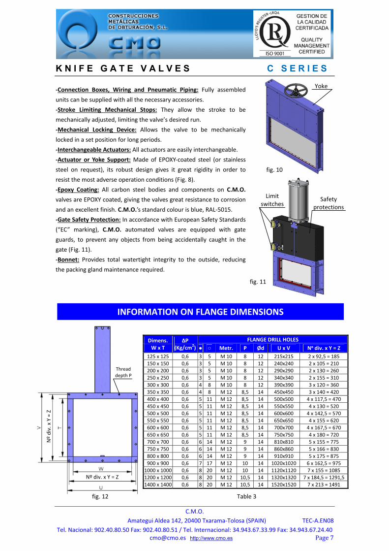
‐Connection Boxes, Wiring and Pneumatic Piping: Fully assembled
units can be supplied with all the necessary accessories. ‐Stroke Limiting Mechanical Stops: They allow the stroke to be
mechanically adjusted, limiting the valve’s desired run. ‐Mechanical Locking Device: Allows the valve to be mechanically
locked in a set position for long periods. ‐Interchangeable Actuators: All actuators are easily interchangeable. ‐Actuator or Yoke Support: Made of EPOXY‐coated steel (or stainless
steel on request), its robust design gives it great rigidity in order to
resist the most adverse operation conditions (Fig. 8). ‐Epoxy Coating: All carbon steel bodies and components on C.M.O.
valves are EPOXY coated, giving the valves great resistance to corrosion
and an excellent finish. C.M.O.’s standard colour is blue, RAL‐5015. ‐Gate Safety Protection: In accordance with European Safety Standards
(“EC” marking), C.M.O. automated valves are equipped with gate
guards, to prevent any objects from being accidentally caught in the
gate (Fig. 11). ‐Bonnet: Provides total watertight integrity to the outside, reducing
the packing gland maintenance required.
Dimens. W x T
ΔP (Kg/cm2)
FLANGE DRILL HOLES
● ○ Metr. P Ød U x V Nº div. x Y = Z
125 x 125 0,6 3 5 M 10 8 12 215x215 2 x 92,5 = 185
150 x 150 0,6 3 5 M 10 8 12 240x240 2 x 105 = 210
200 x 200 0,6 3 5 M 10 8 12 290x290 2 x 130 = 260
250 x 250 0,6 3 5 M 10 8 12 340x340 2 x 155 = 310
300 x 300 0,6 4 8 M 10 8 12 390x390 3 x 120 = 360
350 x 350 0,6 4 8 M 12 8,5 14 450x450 3 x 140 = 420
400 x 400 0,6 5 11 M 12 8,5 14 500x500 4 x 117,5 = 470
450 x 450 0,6 5 11 M 12 8,5 14 550x550 4 x 130 = 520
500 x 500 0,6 5 11 M 12 8,5 14 600x600 4 x 142,5 = 570
550 x 550 0,6 5 11 M 12 8,5 14 650x650 4 x 155 = 620
600 x 600 0,6 5 11 M 12 8,5 14 700x700 4 x 167,5 = 670
650 x 650 0,6 5 11 M 12 8,5 14 750x750 4 x 180 = 720
700 x 700 0,6 6 14 M 12 9 14 810x810 5 x 155 = 775
750 x 750 0,6 6 14 M 12 9 14 860x860 5 x 166 = 830
800 x 800 0,6 6 14 M 12 9 14 910x910 5 x 175 = 875
900 x 900 0,6 7 17 M 12 10 14 1020x1020 6 x 162,5 = 975
1000 x 1000 0,6 8 20 M 12 10 14 1120x1120 7 x 155 = 1085
1200 x 1200 0,6 8 20 M 12 10,5 14 1320x1320 7 x 184,5 = 1291,5
1400 x 1400 0,6 8 20 M 12 10,5 14 1520x1520 7 x 213 = 1491
INFORMATION ON FLANGE DIMENSIONS
Thread depth P
Nº div. x Y = Z
Nº div. x Y = Z
fig. 12 Table 3
Yoke
fig. 10
Limit switches Safety
protections
fig. 11
K N I F E G A T E V A L V E S C S E R I E S
C.M.O.
Amategui Aldea 142, 20400 Txarama‐Tolosa (SPAIN) TEC‐A.EN08
Tel. Nacional: 902.40.80.50 Fax: 902.40.80.51 / Tel. Internacional: 34.943.67.33.99 Fax: [email protected] http://www.cmo.esPage8
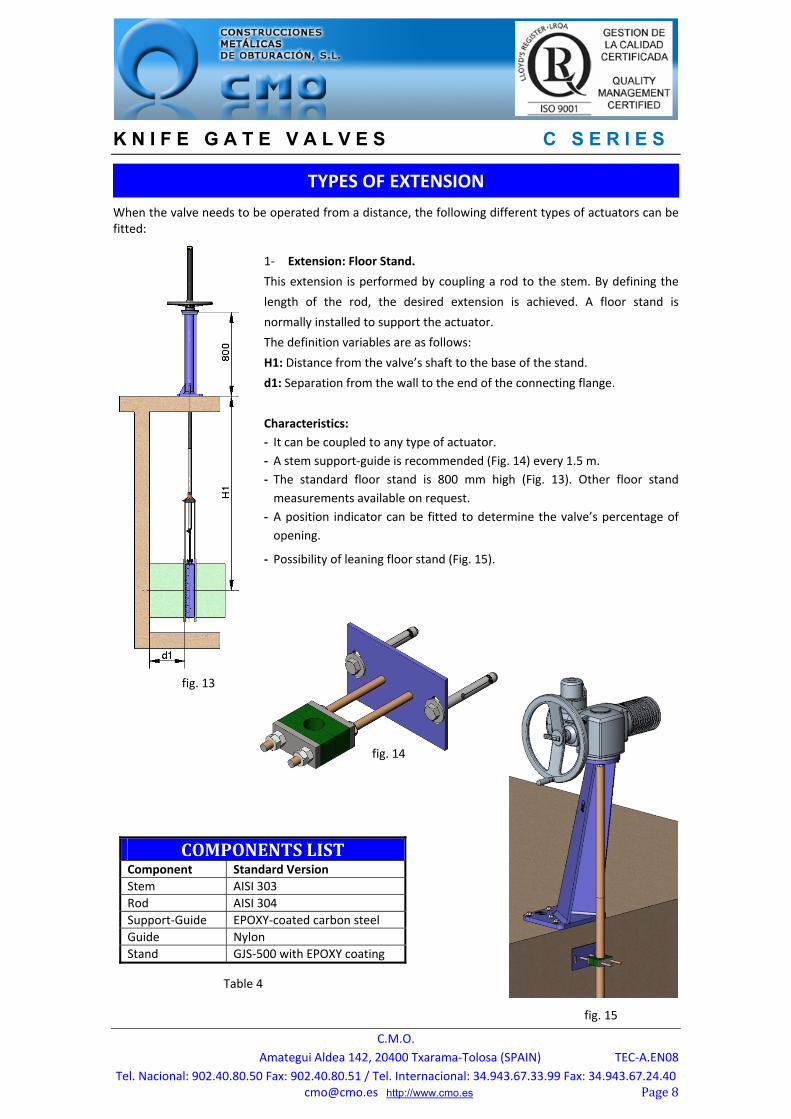
When the valve needs to be operated from a distance, the following different types of actuators can be fitted:
1‐ Extension: Floor Stand.
This extension is performed by coupling a rod to the stem. By defining the
length of the rod, the desired extension is achieved. A floor stand is
normally installed to support the actuator. The definition variables are as follows:
H1: Distance from the valve’s shaft to the base of the stand. d1: Separation from the wall to the end of the connecting flange.
Characteristics:
‐ It can be coupled to any type of actuator.
‐ A stem support‐guide is recommended (Fig. 14) every 1.5 m.
‐ The standard floor stand is 800 mm high (Fig. 13). Other floor stand
measurements available on request.
‐ A position indicator can be fitted to determine the valve’s percentage of
opening.
‐ Possibility of leaning floor stand (Fig. 15).TIPO
DEEXTENSIONES
COMPONENTSLISTComponent Standard Version
Stem AISI 303
Rod AISI 304
Support‐Guide EPOXY‐coated carbon steel
Guide Nylon
Stand GJS‐500 with EPOXY coating
TYPES OF EXTENSION
fig. 14
Table 4
fig. 13
fig. 15
K N I F E G A T E V A L V E S C S E R I E S
C.M.O.
Amategui Aldea 142, 20400 Txarama‐Tolosa (SPAIN) TEC‐A.EN08
Tel. Nacional: 902.40.80.50 Fax: 902.40.80.51 / Tel. Internacional: 34.943.67.33.99 Fax: [email protected] http://www.cmo.esPage9
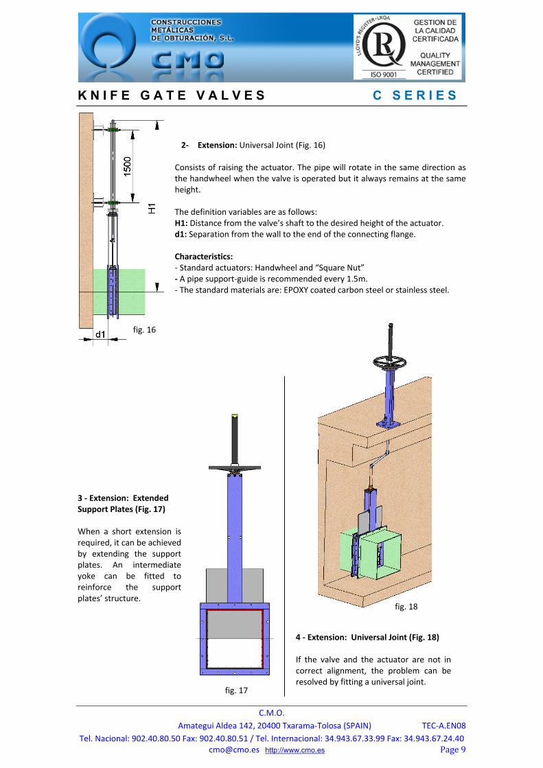
2‐ Extension: Universal Joint (Fig. 16)
Consists of raising the actuator. The pipe will rotate in the same direction as the handwheel when the valve is operated but it always remains at the same height. The definition variables are as follows: H1: Distance from the valve’s shaft to the desired height of the actuator. d1: Separation from the wall to the end of the connecting flange. Characteristics: ‐ Standard actuators: Handwheel and “Square Nut” ‐ A pipe support‐guide is recommended every 1.5m. ‐ The standard materials are: EPOXY coated carbon steel or stainless steel.
3 ‐ Extension: Extended Support Plates (Fig. 17) When a short extension is required, it can be achieved by extending the support plates. An intermediate yoke can be fitted to reinforce the support plates’ structure.
4 ‐ Extension: Universal Joint (Fig. 18) If the valve and the actuator are not in correct alignment, the problem can be resolved by fitting a universal joint.
fig. 16
fig. 17
fig. 18
K N I F E G A T E V A L V E S C S E R I E S
C.M.O.
Amategui Aldea 142, 20400 Txarama‐Tolosa (SPAIN) TEC‐A.EN08
Tel. Nacional: 902.40.80.50 Fax: 902.40.80.51 / Tel. Internacional: 34.943.67.33.99 Fax: [email protected] http://www.cmo.esPage10
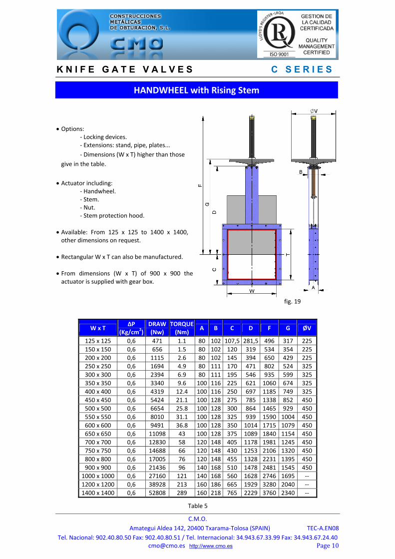
Options: ‐ Locking devices. ‐ Extensions: stand, pipe, plates...
‐ Dimensions (W x T) higher than those
give in the table.
Actuator including: ‐ Handwheel. ‐ Stem. ‐ Nut. ‐ Stem protection hood.
Available: From 125 x 125 to 1400 x 1400, other dimensions on request.
Rectangular W x T can also be manufactured.
From dimensions (W x T) of 900 x 900 the actuator is supplied with gear box.
W x T ΔP
(Kg/cm2) DRAW(Nw)
TORQUE(Nm)
A B C D F G ØV
125 x 125 0,6 471 1.1 80 102 107,5 281,5 496 317 225
150 x 150 0,6 656 1.5 80 102 120 319 534 354 225
200 x 200 0,6 1115 2.6 80 102 145 394 650 429 225
250 x 250 0,6 1694 4.9 80 111 170 471 802 524 325
300 x 300 0,6 2394 6.9 80 111 195 546 935 599 325
350 x 350 0,6 3340 9.6 100 116 225 621 1060 674 325
400 x 400 0,6 4319 12.4 100 116 250 697 1185 749 325
450 x 450 0,6 5424 21.1 100 128 275 785 1338 852 450
500 x 500 0,6 6654 25.8 100 128 300 864 1465 929 450
550 x 550 0,6 8010 31.1 100 128 325 939 1590 1004 450
600 x 600 0,6 9491 36.8 100 128 350 1014 1715 1079 450
650 x 650 0,6 11098 43 100 128 375 1089 1840 1154 450
700 x 700 0,6 12830 58 120 148 405 1178 1981 1245 450
750 x 750 0,6 14688 66 120 148 430 1253 2106 1320 450
800 x 800 0,6 17005 76 120 148 455 1328 2231 1395 450
900 x 900 0,6 21436 96 140 168 510 1478 2481 1545 450
1000 x 1000 0,6 27160 121 140 168 560 1628 2746 1695 ‐‐
1200 x 1200 0,6 38928 213 160 186 665 1929 3280 2040 ‐‐
1400 x 1400 0,6 52808 289 160 218 765 2229 3760 2340 ‐‐
HANDWHEEL with Rising Stem
fig. 19
Table 5

K N I F E G A T E V A L V E S C S E R I E S
C.M.O.
Amategui Aldea 142, 20400 Txarama‐Tolosa (SPAIN) TEC‐A.EN08
Tel. Nacional: 902.40.80.50 Fax: 902.40.80.51 / Tel. Internacional: 34.943.67.33.99 Fax: [email protected] http://www.cmo.esPage11
Suitable when no size limitations exist.
Options: ‐ Square nut.
‐ Locking devices. ‐ Extensions: stand, pipe, plates...
‐ Dimensions (W x T) higher than those
give in the table.
Actuator including: ‐ Handwheel. ‐ Stem. ‐ Guide bearings on the yoke. ‐ Nut.
Available: From 125 x 125 to 1400 x 1400, other dimensions on request.
Rectangular W x T can also be manufactured.
From dimensions (W x T) of 900 x 900 the actuator is supplied with gear box.
W x T
ΔP (Kg/cm2)
DRAW(Nw)
TORQUE(Nm)
A B C D G ØV
125 x 125 0,6 471 1.1 80 102 107,5 281,5 317 225
150 x 150 0,6 656 1.5 80 102 120 319 354 225
200 x 200 0,6 1115 2.6 80 102 145 394 429 225
250 x 250 0,6 1694 4.9 80 111 170 471 524 325
300 x 300 0,6 2394 6.9 80 111 195 546 599 325
350 x 350 0,6 3340 9.6 100 116 225 621 674 325
400 x 400 0,6 4319 12.4 100 116 250 697 749 325
450 x 450 0,6 5424 21.1 100 128 275 785 852 450
500 x 500 0,6 6654 25.8 100 128 300 864 929 450
550 x 550 0,6 8010 31.1 100 128 325 939 1004 450
600 x 600 0,6 9491 36.8 100 128 350 1014 1079 450
650 x 650 0,6 11098 43 100 128 375 1089 1154 450
700 x 700 0,6 12830 58 120 148 405 1178 1245 450
750 x 750 0,6 14688 66 120 148 430 1253 1320 450
800 x 800 0,6 17005 76 120 148 455 1328 1395 450
900 x 900 0,6 21436 96 140 168 510 1478 1545 450
1000 x 1000 0,6 27160 121 140 168 560 1628 1695 ‐‐
1200 x 1200 0,6 38928 213 160 186 665 1929 2040 ‐‐
1400 x 1400 0,6 52808 289 160 218 765 2229 2340 ‐‐
HANDWHEEL with Non‐Rising Stem
Table 6
fig. 20

K N I F E G A T E V A L V E S C S E R I E S
C.M.O.
Amategui Aldea 142, 20400 Txarama‐Tolosa (SPAIN) TEC‐A.EN08
Tel. Nacional: 902.40.80.50 Fax: 902.40.80.51 / Tel. Internacional: 34.943.67.33.99 Fax: [email protected] http://www.cmo.esPage12
Widely used in raised installations with difficult access, the handwheel is fitted in vertical position.
Options: ‐ Locking devices. ‐ Extensions: stand, pipe, plates... ‐ Non‐rising stem.
‐ Dimensions (W x T) higher than those
give in the table.
Including: ‐ Handwheel. ‐ Stem. ‐ Nut. ‐ Hood. ‐ Chain.
Available: From 125 x 125 to 1400 x 1400, other dimensions on request.
Rectangular W x T can also be manufactured.
From dimensions (W x T) of 900 x 900 the actuator is supplied with gear box, see * in table.
W x T ΔP
(Kg/cm2) DRAW (Nw)
TORQUE(Nm)
A B C D F G ØV
125 x 125 0,6 471 1.1 80 102 107,5 281,5 496 317 225
150 x 150 0,6 656 1.5 80 102 120 319 534 354 225
200 x 200 0,6 1115 2.6 80 102 145 394 650 429 225
250 x 250 0,6 1694 4.9 80 111 170 471 802 524 300
300 x 300 0,6 2394 6.9 80 111 195 546 935 599 300
350 x 350 0,6 3340 9.6 100 116 225 621 1060 674 300
400 x 400 0,6 4319 12.4 100 116 250 697 1185 749 300
450 x 450 0,6 5424 21.1 100 128 275 785 1338 852 402
500 x 500 0,6 6654 25.8 100 128 300 864 1465 929 402
550 x 550 0,6 8010 31.1 100 128 325 939 1590 1004 402
600 x 600 0,6 9491 36.8 100 128 350 1014 1715 1079 402
650 x 650 0,6 11098 43 100 128 375 1089 1840 1154 402
700 x 700 0,6 12830 58 120 148 405 1178 1981 1245 402
750 x 750 0,6 14688 66 120 148 430 1253 2106 1320 402
800 x 800 0,6 17005 76 120 148 455 1328 2231 1395 402
900 x 900 0,6 21436 96 140 168 510 1478 2481 1545 402
1000 x 1000 0,6 27160 121 140 168 560 1628 2746 1695 402*
1200 x 1200 0,6 38928 213 160 186 665 1929 3280 2040 402*
1400 x 1400 0,6 52808 289 160 218 765 2229 3760 2340 402*
CHAINWHEEL
Table 7
fig. 21
K N I F E G A T E V A L V E S C S E R I E S
C.M.O.
Amategui Aldea 142, 20400 Txarama‐Tolosa (SPAIN) TEC‐A.EN08
Tel. Nacional: 902.40.80.50 Fax: 902.40.80.51 / Tel. Internacional: 34.943.67.33.99 Fax: [email protected] http://www.cmo.esPage13
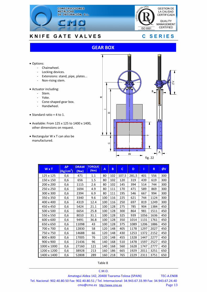
Options: ‐ Chainwheel. ‐ Locking devices. ‐ Extensions: stand, pipe, plates... ‐ Non‐rising stem.
Actuator including: ‐ Stem. ‐ Yoke. ‐ Cone‐shaped gear box. ‐ Handwheel.
Standard ratio = 4 to 1.
Available: From 125 x 125 to 1400 x 1400, other dimensions on request.
Rectangular W x T can also be manufactured.
W x T ΔP
(Kg/cm2) DRAW (Nw)
TORQUE (Nm) A B C D I R ØV
125 x 125 0,6 471 1.1 80 102 107,5 281,5 401 556 300
150 x 150 0,6 656 1.5 80 102 120 319 439 619 300
200 x 200 0,6 1115 2.6 80 102 145 394 514 744 300
250 x 250 0,6 1694 4.9 80 111 170 471 589 869 300
300 x 300 0,6 2394 6.9 80 111 195 546 667 994 300
350 x 350 0,6 3340 9.6 100 116 225 621 744 1124 300
400 x 400 0,6 4319 12.4 100 116 250 697 819 1249 300
450 x 450 0,6 5424 21.1 100 128 275 785 904 1384 450
500 x 500 0,6 6654 25.8 100 128 300 864 981 1511 450
550 x 550 0,6 8010 31.1 100 128 325 939 1056 1636 450
600 x 600 0,6 9491 36.8 100 128 350 1014 1131 1761 450
650 x 650 0,6 11098 43 100 128 375 1089 1206 1886 450
700 x 700 0,6 12830 58 120 148 405 1178 1297 2027 450
750 x 750 0,6 14688 66 120 148 430 1253 1372 2152 450
800 x 800 0,6 17005 76 120 148 455 1328 1447 2277 450
900 x 900 0,6 21436 96 140 168 510 1478 1597 2527 450
1000 x 1000 0,6 27160 121 140 168 560 1628 1747 2777 450
1200 x 1200 0,6 38928 213 160 186 665 1929 2011 3251 650
1400 x 1400 0,6 52808 289 160 218 765 2229 2311 3751 650
GEAR BOX
fig. 22
Table 8

K N I F E G A T E V A L V E S C S E R I E S
C.M.O.
Amategui Aldea 142, 20400 Txarama‐Tolosa (SPAIN) TEC‐A.EN08
Tel. Nacional: 902.40.80.50 Fax: 902.40.80.51 / Tel. Internacional: 34.943.67.33.99 Fax: [email protected] http://www.cmo.esPage14
The air supply pressure to the cylinder is a minimum of 6 Kg/cm² and a maximum of 10 Kg/cm², the air must be dry and lubricated.
For pneumatic cylinders up to Ø200, the jacket and covers are made of aluminium, the rod is AISI304, the piston is rubber‐coated steel and the O‐ring seals are made of nitrile. For cylinders larger than Ø200 the covers are made of nodular cast iron or carbon steel.
On request, we can also supply the actuator made entirely of stainless steel, especially for installation in corrosive atmospheres.
Available: From 125 x 125 to 1400 x 1400, other dimensions on request.
Rectangular W x T can also be manufactured.
W x T ΔP
(Kg/cm2)DRAW (Nw)
A B C D N Q ØCYL
Ø ROD
S (B.S.P.)
125 x 125 0,6 471 80 102 107,5 281,5 511 90 Ø80 Ø20 1/4"
150 x 150 0,6 656 80 102 120 319 574 90 Ø80 Ø20 1/4"
200 x 200 0,6 1115 80 102 145 394 699 90 Ø80 Ø20 1/4"
250 x 250 0,6 1694 80 111 170 471 824 90 Ø80 Ø20 1/4"
300 x 300 0,6 2394 80 111 195 546 949 90 Ø80 Ø20 1/4"
350 x 350 0,6 3340 100 116 225 621 1074 110 Ø100 Ø20 1/4"
400 x 400 0,6 4319 100 116 250 697 1215 135 Ø125 Ø25 1/4"
450 x 450 0,6 5424 100 128 275 785 1351 135 Ø125 Ø25 1/4"
500 x 500 0,6 6654 100 128 300 864 1486 170 Ø160 Ø30 1/4"
550 x 550 0,6 8010 100 128 325 939 1611 170 Ø160 Ø30 1/4"
600 x 600 0,6 9491 100 128 350 1014 1736 170 Ø160 Ø30 1/4"
650 x 650 0,6 11098 100 128 375 1089 1861 170 Ø160 Ø30 1/4"
700 x 700 0,6 12830 120 148 405 1178 2014 215 Ø200 Ø30 3/8"
750 x 750 0,6 14688 120 148 430 1253 2182 270 Ø250 Ø40 3/8"
800 x 800 0,6 17005 120 148 455 1328 2307 270 Ø250 Ø40 3/8"
900 x 900 0,6 21436 140 168 510 1478 2560 270 Ø250 Ø40 3/8"
1000 x 1000 0,6 27160 140 168 560 1628 2815 382 Ø300 Ø45 1/2"
1200 x 1200 0,6 38928 160 186 665 1929 3310 426 Ø350 Ø45 1/2"
1400 x 1400 0,6 52808 160 218 765 2229 3877 508 Ø400 Ø50 1/2"
DOUBLE‐ACTING PNEUMATIC CYLINDER
Table 9
fig. 23

K N I F E G A T E V A L V E S C S E R I E S
C.M.O.
Amategui Aldea 142, 20400 Txarama‐Tolosa (SPAIN) TEC‐A.EN08
Tel. Nacional: 902.40.80.50 Fax: 902.40.80.51 / Tel. Internacional: 34.943.67.33.99 Fax: [email protected] http://www.cmo.esPage15
The air supply pressure to the cylinder is a minimum of
6 Kg/cm² and a maximum of 10 Kg/cm², the air must be
dry and lubricated.
Available for opening or closing in case of air supply failure (spring opening or closing).
The actuator design is spring activated for 300x300 valves. For larger strokes the actuator contains a
double‐acting cylinder and an air tank which stores the
volume of air necessary to perform the last movement
in the event of a air supply failure.
The jacket is made of aluminium, the covers of nodular
cast iron or carbon steel, the rod of AISI304, the piston
of rubber‐coated steel and the O‐ring seals of nitrile.
Available: From 125 x 125 to 300 x 300, other dimensions on request.
Rectangular W x T can also be manufactured.
W x T ΔP
(Kg/cm2) DRAW (Nw)
A B C D Y Q Ø CYL Ø
ROD S
(B.S.P.)
125 x 125 0,6 471 80 102 107,5 281,5 816 135 Ø125 Ø25 1/4"
150 x 150 0,6 656 80 102 120 319 861 135 Ø125 Ø25 1/4"
200 x 200 0,6 1115 80 102 145 394 939 135 Ø125 Ø25 1/4"
250 x 250 0,6 1694 80 111 170 471 1130 135 Ø125 Ø25 1/4"
300 x 300 0,6 2394 80 111 195 546 1255 135 Ø125 Ø25 1/4"
SINGLE‐ACTING PNEUMATIC CYLINDER
Table 10
fig. 24

K N I F E G A T E V A L V E S C S E R I E S
C.M.O.
Amategui Aldea 142, 20400 Txarama‐Tolosa (SPAIN) TEC‐A.EN08
Tel. Nacional: 902.40.80.50 Fax: 902.40.80.51 / Tel. Internacional: 34.943.67.33.99 Fax: [email protected] http://www.cmo.esPage16
This actuator is automatic and includes the following parts:
‐ Electric motor. ‐ Stem. ‐ Yoke.
The electric motor includes: ‐ Emergency manual handwheel. ‐ Limit switches. ‐ Torque switches.
Options: ‐ Different types and brands. ‐ Non‐rising stem.
ISO 5210 / DIN 3338 Flanges.
Available: 125 x 125 to 1400 x 1400, other DN on request.
Rectangular W x T can also be manufactured.
From dimensions (W x T) of 900 x 900 the motor uses a gear box.
W x T ΔP
(Kg/cm2) DRAW (Nw)
TORQUE(Nm)
A B C D E J K M X
125 x 125 0,6 471 1.1 80 102 108 282 436 265 250 631 237
150 x 150 0,6 656 1.5 80 102 120 319 473 265 250 668 237
200 x 200 0,6 1115 2.6 80 102 145 394 548 265 250 743 237
250 x 250 0,6 1694 4.9 80 111 170 471 623 265 250 831 237
300 x 300 0,6 2394 6.9 80 111 195 546 698 265 250 956 237
350 x 350 0,6 3340 9.6 100 116 225 621 778 265 250 1086 237
400 x 400 0,6 4319 12.4 100 116 250 697 853 265 250 1211 237
450 x 450 0,6 5424 21.1 100 128 275 785 950 265 250 1365 247
500 x 500 0,6 6654 25.8 100 128 300 864 1027 265 250 1492 247
550 x 550 0,6 8010 31.1 100 128 325 939 1102 265 250 1617 247
600 x 600 0,6 9491 36.8 100 128 350 1014 1177 265 250 1742 247
650 x 650 0,6 11098 43 100 128 375 1089 1252 265 250 1867 247
700 x 700 0,6 12830 58 120 148 405 1178 1343 265 250 2008 247
750 x 750 0,6 14688 66 120 148 430 1253 1418 265 250 2133 247
800 x 800 0,6 17005 76 120 148 455 1328 1493 265 250 2258 247
900 x 900 0,6 21436 96 140 168 510 1478 1643 265 250 2508 247
1000 x 1000 0,6 27160 121 140 168 560 1628 1793 282 256 2758 382
1200 x 1200 0,6 38928 213 160 186 665 1929 2084 282 256 3229 382
1400 x 1400 0,6 52808 289 160 218 765 2229 2384 282 256 3729 382
ELECTRIC ACTUATOR
Table 11
fig. 25
K N I F E G A T E V A L V E S C S E R I E S
C.M.O.
Amategui Aldea 142, 20400 Txarama‐Tolosa (SPAIN) TEC‐A.EN08
Tel. Nacional: 902.40.80.50 Fax: 902.40.80.51 / Tel. Internacional: 34.943.67.33.99 Fax: [email protected] http://www.cmo.esPage17
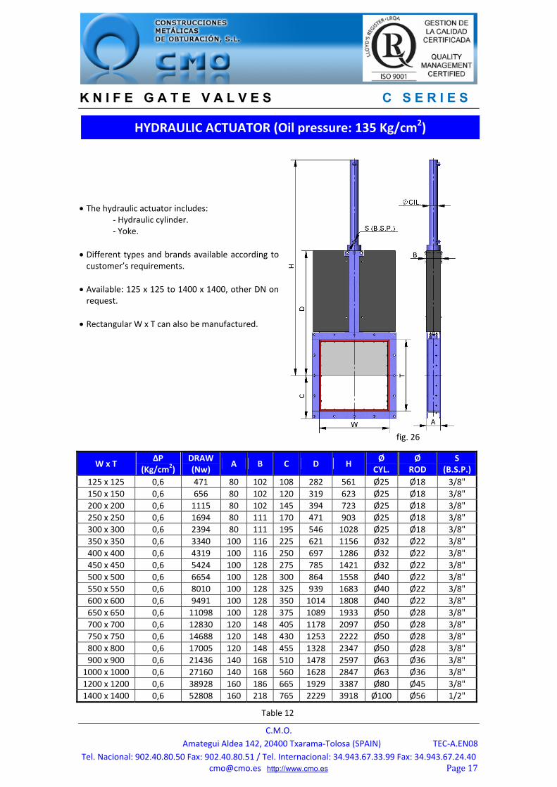
The hydraulic actuator includes: ‐ Hydraulic cylinder. ‐ Yoke.
Different types and brands available according to customer’s requirements.
Available: 125 x 125 to 1400 x 1400, other DN on request.
Rectangular W x T can also be manufactured.
W x T ΔP
(Kg/cm2) DRAW (Nw)
A B C D H Ø
CYL. Ø
ROD S
(B.S.P.)
125 x 125 0,6 471 80 102 108 282 561 Ø25 Ø18 3/8"
150 x 150 0,6 656 80 102 120 319 623 Ø25 Ø18 3/8"
200 x 200 0,6 1115 80 102 145 394 723 Ø25 Ø18 3/8"
250 x 250 0,6 1694 80 111 170 471 903 Ø25 Ø18 3/8"
300 x 300 0,6 2394 80 111 195 546 1028 Ø25 Ø18 3/8"
350 x 350 0,6 3340 100 116 225 621 1156 Ø32 Ø22 3/8"
400 x 400 0,6 4319 100 116 250 697 1286 Ø32 Ø22 3/8"
450 x 450 0,6 5424 100 128 275 785 1421 Ø32 Ø22 3/8"
500 x 500 0,6 6654 100 128 300 864 1558 Ø40 Ø22 3/8"
550 x 550 0,6 8010 100 128 325 939 1683 Ø40 Ø22 3/8"
600 x 600 0,6 9491 100 128 350 1014 1808 Ø40 Ø22 3/8"
650 x 650 0,6 11098 100 128 375 1089 1933 Ø50 Ø28 3/8"
700 x 700 0,6 12830 120 148 405 1178 2097 Ø50 Ø28 3/8"
750 x 750 0,6 14688 120 148 430 1253 2222 Ø50 Ø28 3/8"
800 x 800 0,6 17005 120 148 455 1328 2347 Ø50 Ø28 3/8"
900 x 900 0,6 21436 140 168 510 1478 2597 Ø63 Ø36 3/8"
1000 x 1000 0,6 27160 140 168 560 1628 2847 Ø63 Ø36 3/8"
1200 x 1200 0,6 38928 160 186 665 1929 3387 Ø80 Ø45 3/8"
1400 x 1400 0,6 52808 160 218 765 2229 3918 Ø100 Ø56 1/2"
HYDRAULIC ACTUATOR (Oil pressure: 135 Kg/cm2)
fig. 26
Table 12