
Unica He Installation and Servicing Manual
40
Installation & Servicing Instructions THESE INSTRUCTIONS TO BE RETAINED BY USER Vokèra is a licensed member of the Benchmark scheme which aims to improve the standards of installation and commissioning of domestic hot water systems in the UK. Unica HE High efficiency combi boiler
Transcript of Unica He Installation and Servicing Manual

Installation
& Servicing
Instructions
THESE INSTRUCTIONSTO BE RETAINEDBY USER
Vokèra is a licensed member of the Benchmark schemewhich aims to improve the standards of installation and commissioning of domestic hot water systems in the UK.
Unica HEHigh efficiency combi boiler
ContentsDesign principles & operating sequence Page1.1 Principle components 31.2 Mode of operation (at rest) 31.3 Mode of operation (heating) 31.4 Mode of operation (Hot water) 31.5 Safety devices 3
Technical data Page2.1 Central heating 42.2 Domestic hot water 42.3 Gas pressures 42.4 Expansion vessel 42.5 Dimensions 42.6 Clearances 42.7 Connections 42.8 Electrical 42.9 Flue details (concentric) 42.9A Flue details (twin pipes) 42.9B Flue details (80/125) 42.10 Efficiency 42.11 Emissions 42.12 Pump duty 5
General requirements (UK) Page3.1 Related documents 63.2 Location of appliance 63.3 Gas supply 63.4 Flue system 63.5 Air supply 63.6 Water circulation 63.7 Electrical supply 73.8 Mounting on a combustible surface 73.9 Timber framed buildings 73.10 Inhibitors 73.11 Showers 7
General requirements (EIRE) Page3A.1 Related documents 83A.2 Location of appliance 83A.3 Gas supply 83A.4 Flue system 83A.5 Air supply 83A.6 Water circulation 83A.7 Electrical supply 93A.8 Mounting on a combustible surface 93A.9 Timber framed buildings 93A.10 Inhibitors 93A.11 Showers 93A.12 Declaration of conformity 9
Installation Page4.1 Delivery 104.2 Contents 104.3 Unpacking 104.4 Preparation for mounting the appliance 104.5 Fitting the flue 104.6 Connecting the gas & water 144.7 Electrical connections 15
Commissioning Page5.1 Gas supply installation 165.2 The heating system 165.3 Initial filling of the system 165.4 Initial flushing of the system 165.5 Pre-operation checks 165.6 Initial lighting 165.7 Checking gas pressure & combustion analysis 165.8 Final flushing of the heating system 175.9 Setting the boiler operating temperature 175.10 Setting the system design pressure 175.11 Regulating the central heating system 175.12 Final checks 175.13 Instructing the user 17
Servicing Page6.1 General 186.2 Routine annual servicing 186.3 Replacement of components 186.4 Component removal procedure 186.5 Pump assembly 186.6 Safety valve 196.7 Lower automatic air release valves 196.8 Water pressure switch 196.9 Primary thermistor 196.10 Return thermistor 196.11 Printed circuit board 196.12 Gas valve 196.13 Electrodes and condense sensor 206.14 Flue fan & mixer 206.15 Burner 206.16 Main heat exchanger 206.17 Automatic by-pass 216.18 Expansion vessel 216.19 Condense trap removal 216.20 Flue collector removal 21
Checks, adjustments and fault finding Page7.1 Checking appliance operation 237.2 Appliance modes of operation 237.3 Appliance fan speed 247.4 Checking the CO2 & adjusting the valve 247.5 Combustion analysis test 257.6 Checking the expansion vessel 257.7 External faults 257.8 Electrical checks 257.9 Fault finding 267.10 Component values & characteristics 267.11 Final fault codes 267.12 Boiler configuration 26
Wiring diagrams Page8.1 External wiring 278.2 Typical control applications 278.3 Other devices 278.4 Vokera twin-channel programmer 27
Exploded diagrams Page9.1 Table 1 299.2 Table 2 309.3 Table 3 319.4 Table 4 329.5 Table 5 33
L.P.G. instructions Page10.1 Related documents 3410.2 Technical data 3410.3 Converting the appliance gas type 3410.4 Gas supply 3410.5 Gas supply installation 3410.6 Adjusting the gas valve 3410.7 Appliance fan speed 35
Benchmark 36
1
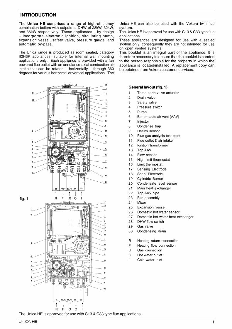
The Unica HE comprises a range of high-efficiencycombination boilers with outputs to DHW of 28kW, 32kW,and 36kW respectively. These appliances – by design– incorporate electronic ignition, circulating pump,expansion vessel, safety valve, pressure gauge, andautomatic by-pass.
The Unica range is produced as room sealed, categoryII2H3P appliances, suitable for internal wall mountingapplications only. Each appliance is provided with a fanpowered flue outlet with an annular co-axial combustion airintake that can be rotated – horizontally – through 360degrees for various horizontal or vertical applications. The
Unica HE can also be used with the Vokera twin fluesystem.The Unica HE is approved for use with C13 & C33 type flueapplications.These appliances are designed for use with a sealedsystem only; consequently they are not intended for useon open vented systems.This booklet is an integral part of the appliance. It istherefore necessary to ensure that the booklet is handedto the person responsible for the property in which theappliance is located/installed. A replacement copy canbe obtained from Vokera customer services.
INTRODUCTION
The Unica HE is approved for use with C13 & C33 type flue applications.
fig. 1
General layout (fig. 1)1 Three porte valve actuator2 Drain valve3 Safety valve4 Pressure switch5 Pump6 Bottom auto air vent (AAV)7 Injector8 Condense trap9 Return sensor10 Flue gas analysis test point11 Flue outlet & air intake12 Ignition transformer13 Top AAV14 Flow sensor15 High limit thermostat16 Limit thermostat17 Sensing Electrode18 Spark Electrode19 Cylindric Burner20 Condensate level sensor21 Main heat exchanger22 Top AAV pipe23 Fan assembly24 Mixer25 Expansion vessel26 Domestic hot water sensor27 Domestic hot water heat exchanger28 DHW flow switch29 Gas valve30 Condensing drain
R Heating return connectionF Heating flow connectionG Gas connectionO Hot water outletI Cold water inlet
R F G O I
R F G O I

2
Fig. 1A
MODE SELECTORSWITCH
RED LEDGREEN LEDHEATING
TEMPERATURESELECTOR
2-digit LEDdisplay
HYDROMETRE
DHWTEMPERATURE
SELECTOR
Hot water only Select this position if you want the boiler to supply hot water only (no heating)
Boiler at OFF/standby Select this position when you want the boiler to be switched off or shortperiods (days) or if the boiler requires to be reset (refer to users handbook)
Heating & hot water (economy) Select this position when you want the boiler to respond to a heating requestfrom the time-clock/programmer
Heating & hot water with pre-heat Select this position when you want the boiler to respond to a heating requestfrom the time-clock/programmer (comfort) and you want the domestic hotwater to be pre-heated
DHW temperature selector Move the selector clockwise to increase the hot water outlet temperature, orcounter-clockwise to reduce the temperature
Heating temperature selector Move the selector clockwise to increase the heating outlet temperature, orcounter-clockwise to reduce the temperature
2-digit LED display Displays the current outlet temperature of the boiler. During a fault condition,the appropriate fault code will be displayed (refere to the users handbook forinstructions regarding fault codes)
Green LED lit Boiler is working/responding to a heating/hot water request
Red LED lit Boiler has identified a fault and has failed-safe. Refer to users handbook forinstructions on how to reset
Pressure gauge Ensure the system pressure is set correctly (minimum 0.5-bar)
3
SECTION 1 DESIGN PRINCIPLES AND OPERATING SEQUENCE
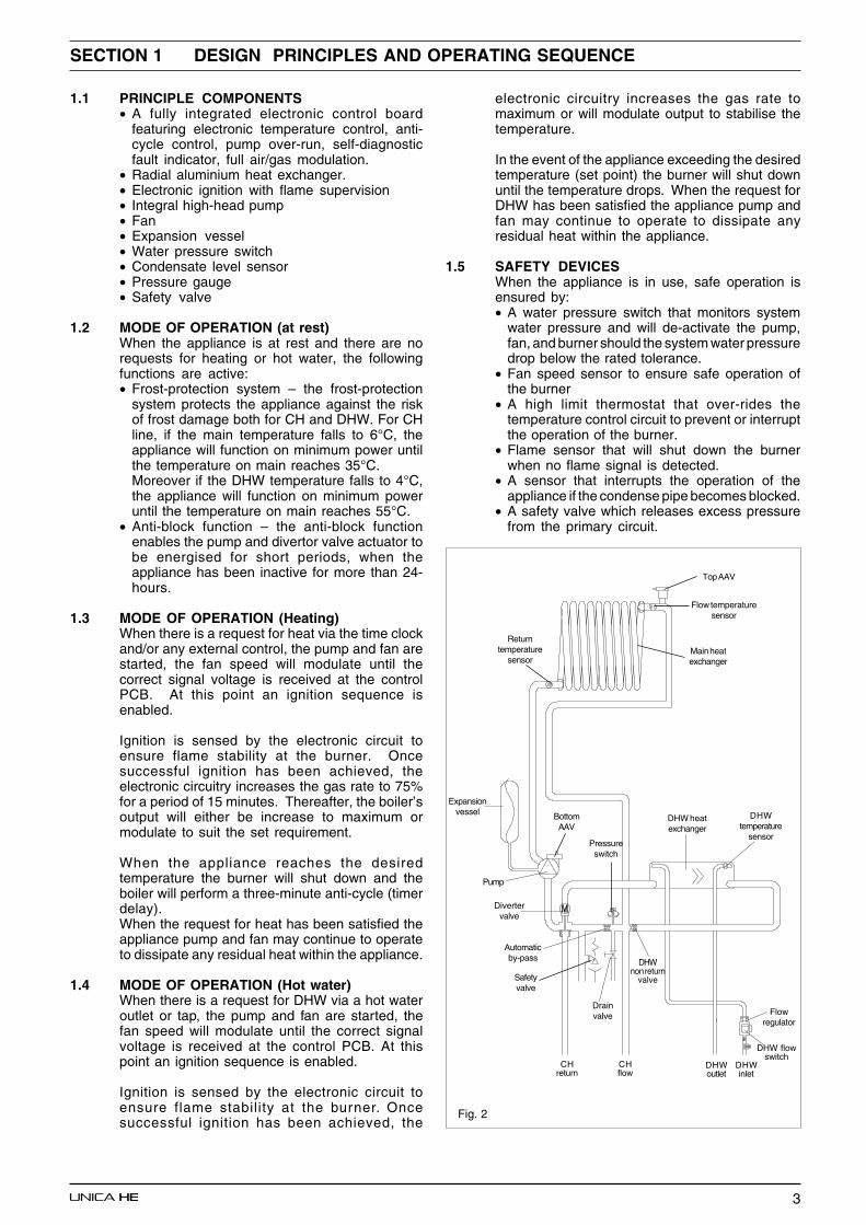
1.1 PRINCIPLE COMPONENTS• A fully integrated electronic control board
featuring electronic temperature control, anti-cycle control, pump over-run, self-diagnosticfault indicator, full air/gas modulation.
• Radial aluminium heat exchanger.• Electronic ignition with flame supervision• Integral high-head pump• Fan• Expansion vessel• Water pressure switch• Condensate level sensor• Pressure gauge• Safety valve
1.2 MODE OF OPERATION (at rest)When the appliance is at rest and there are norequests for heating or hot water, the followingfunctions are active:• Frost-protection system – the frost-protection
system protects the appliance against the riskof frost damage both for CH and DHW. For CHline, if the main temperature falls to 6°C, theappliance will function on minimum power untilthe temperature on main reaches 35°C.Moreover if the DHW temperature falls to 4°C,the appliance will function on minimum poweruntil the temperature on main reaches 55°C.
• Anti-block function – the anti-block functionenables the pump and divertor valve actuator tobe energised for short periods, when theappliance has been inactive for more than 24-hours.
1.3 MODE OF OPERATION (Heating)When there is a request for heat via the time clockand/or any external control, the pump and fan arestarted, the fan speed will modulate until thecorrect signal voltage is received at the controlPCB. At this point an ignition sequence isenabled.
Ignition is sensed by the electronic circuit toensure flame stability at the burner. Oncesuccessful ignition has been achieved, theelectronic circuitry increases the gas rate to 75%for a period of 15 minutes. Thereafter, the boiler’soutput will either be increase to maximum ormodulate to suit the set requirement.
When the appliance reaches the desiredtemperature the burner will shut down and theboiler will perform a three-minute anti-cycle (timerdelay).When the request for heat has been satisfied theappliance pump and fan may continue to operateto dissipate any residual heat within the appliance.
1.4 MODE OF OPERATION (Hot water)When there is a request for DHW via a hot wateroutlet or tap, the pump and fan are started, thefan speed will modulate until the correct signalvoltage is received at the control PCB. At thispoint an ignition sequence is enabled.
Ignition is sensed by the electronic circuit toensure flame stability at the burner. Oncesuccessful ignition has been achieved, the
electronic circuitry increases the gas rate tomaximum or will modulate output to stabilise thetemperature.
In the event of the appliance exceeding the desiredtemperature (set point) the burner will shut downuntil the temperature drops. When the request forDHW has been satisfied the appliance pump andfan may continue to operate to dissipate anyresidual heat within the appliance.
1.5 SAFETY DEVICESWhen the appliance is in use, safe operation isensured by:• A water pressure switch that monitors system
water pressure and will de-activate the pump,fan, and burner should the system water pressuredrop below the rated tolerance.
• Fan speed sensor to ensure safe operation ofthe burner
• A high limit thermostat that over-rides thetemperature control circuit to prevent or interruptthe operation of the burner.
• Flame sensor that will shut down the burnerwhen no flame signal is detected.
• A sensor that interrupts the operation of theappliance if the condense pipe becomes blocked.
• A safety valve which releases excess pressurefrom the primary circuit.
Fig. 2
Expansionvessel
Safetyvalve
Pump
Returntemperature
sensorMain heatexchanger
BottomAAV
Pressureswitch
DHW heatexchanger
Divertervalve
Drainvalve
DHWtemperature
sensor
Flow temperaturesensor
Top AAV
Automaticby-pass DHW
non returnvalve
Flowregulator
CHreturn
CHflow
DHW flowswitch
DHWinlet
DHWoutlet
4
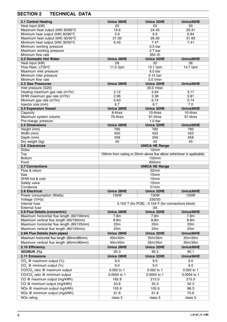
SECTION 2 TECHNICAL DATA
2.1 Central Heating Unica 28HE Unica 32HE Unica36HEHeat input (kW) 20 25 30Maximum heat output (kW) 60/80°C 19.6 24.45 29.31Minimum heat output (kW) 60/80°C 5.9 6.9 6.84Maximum heat output (kW) 30/50°C 21.00 26.30 31.83Minimum heat output (kW) 30/50°C 6.40 7.47 7.41Minimum working pressure 0.5 barMaximum working pressure 2.7 barMinimum flow rate 350 l/h2.2 Domestic Hot Water Unica 28HE Unica 32HE Unica36HEHeat input (kW) 28 32 36Flow Rate: ∆T35oC 11.5 l/pm 13.1 l/pm 14.7 l/pmMaximum inlet pressure 6.0 barMinimum inlet pressure 0.15 barMinimum flow rate 2.0 l/min2.3 Gas Pressures Unica 28HE Unica 32HE Unica36HEInlet pressure (G20) 20.0 mbarHeating maximum gas rate (m3/hr) 2.12 2.64 3.17DHW maximum gas rate (m3/hr) 2.96 3.38 3.81Minimum gas rate (m3/hr) 0.63 0.74 0.74Injector size (mm) 6.7 6.7 7.02.4 Expansion Vessel Unica 28HE Unica 32HE Unica36HECapacity 8-litres 10-litres 10-litresMaximum system volume 76-litres 91-litres 91-litresPre-charge pressure 1.0 bar2.5 Dimensions Unica 28HE Unica 32HE Unica36HEHeight (mm) 780 780 780Width (mm) 400 450 450Depth (mm) 358 358 358Dry weight (kg) 40 42 452.6 Clearances UNICA HE RangeSides 12mmTop 150mm from casing or 25mm above flue elbow (whichever is applicable)Bottom 150mmFront 600mm2.7 Connections UNICA HE RangeFlow & return 22mmGas 15mmDHW hot & cold 15mmSafety valve 15mmCondense 21mm2.8 Electrical Unica 28HE Unica 32HE Unica36HEPower consumption (Watts) 150W 150W 150WVoltage (V/Hz) 230/50Internal fuse 3.15A T (for PCB) - 3.15A F (for connections block)External fuse 3A2.9 Flue Details (concentric) Unica 28HE Unica 32HE Unica36HEMaximum horizontal flue length (60/100mm) 7.8m 7.8m 7.8mMaximum vertical flue length (60/100mm) 8.8m 8.8m 8.8mMaximum horizontal flue length (80/125mm) 20m 20m 20mMaximum vertical flue length (80/125mm) 25m 25m 25m2.9A Flue Details (twin pipes) Unica 28HE Unica 32HE Unica36HEMaximum horizontal flue length (80mm/80mm) 40m/40m 35m/35m 35m/35mMaximum vertical flue length (80mm/80mm) 40m/40m 35m/35m 35m/35m2.10 Efficiency Unica 28HE Unica 32HE Unica36HESEDBUK (%) 90.3 90.2 90.12.11 Emissions Unica 28HE Unica 32HE Unica36HECO2 @ maximum output (%) 9.0 9.0 9.0CO2 @ minimum output (%) 9.0 9.0 9.0CO/CO2 ratio @ maximum output 0.002 to 1 0.002 to 1 0.002 to 1CO/CO2 ratio @ minimum output 0.0004 to 1 0.0004 to 1 0.0004 to 1CO @ maximum output (mg/kWh) 182.8 215.0 215.0CO @ minimum output (mg/kWh) 53.8 32.3 32.3NOx @ maximum output mg/kWh) 105.9 105.9 88.3NOx @ minimum output (mg/kWh) 61.8 61.8 70.6NOx rating class 5 class 5 class 5
5
0,0
0,2
0,4
0,6
0,8
1,0
1,2
1,4
1,6
1,8
2,0
2,2
2,4
2,6
2,8
3,0
3,2
3,4
3,6
3,8
4,0
4,2
4,4
4,6
4,8
5,0
0 100 200 300 400 500 600 700 800 900 1000 1100 1200 1300 1400 1500
Fig. 4
Key Location Minimum distance
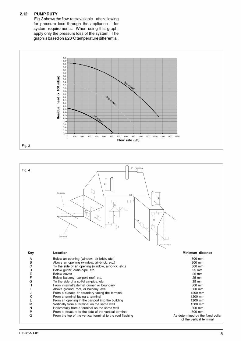
A Below an opening (window, air-brick, etc.) 300 mmB Above an opening (window, air-brick, etc.) 300 mmC To the side of an opening (window, air-brick, etc.) 300 mmD Below gutter, drain-pipe, etc. 25 mmE Below eaves 25 mmF Below balcony, car-port roof, etc. 25 mmG To the side of a soil/drain-pipe, etc. 25 mmH From internal/external corner or boundary 300 mmI Above ground, roof, or balcony level 300 mmJ From a surface or boundary facing the terminal 1200 mmK From a terminal facing a terminal 1200 mmL From an opening in the car-port into the building 1200 mmM Vertically from a terminal on the same wall 1500 mmN Horizontally from a terminal on the same wall 300 mmP From a structure to the side of the vertical terminal 500 mmQ From the top of the vertical terminal to the roof flashing As determined by the fixed collar
of the vertical terminal
Fig. 3
2.12 PUMP DUTYFig. 3 shows the flow-rate available – after allowingfor pressure loss through the appliance – forsystem requirements. When using this graph,apply only the pressure loss of the system. Thegraph is based on a 20oC temperature differential.
Flow rate (l/h)
Res
idu
al h
ead
(x
100
mb
ar)
1st speed
2nd speed
3rd speed

6
SECTION 3 GENERAL REQUIREMENTS (UK)
This appliance must be installed by a competentperson in accordance with the Gas Safety(Installation & Use) Regulations.
3.1 RELATED DOCUMENTSThe installation of this boiler must be in accordancewith the relevant requirements of the Gas Safety(Installation & Use) Regulations, the local buildingregulations, the current I.E.E. wiring regulations,the bylaws of the local water undertaking, theBuilding Standards (Scotland) Regulation, andBuilding Standards (Northern Ireland) Regulations.
It should be in accordance also with any relevantrequirements of the local authority and the relevantrecommendations of the following British StandardCodes of Practice.
3.2 LOCATION OF APPLIANCEThe appliance may be installed in any room orinternal space, although particular attention isdrawn to the requirements of the current I.E.E.wiring regulations, and in Scotland, the electricalprovisions of the Building Regulations, with respectto the installation of the appliance in a room orinternal space containing a bath or shower.
When an appliance is installed in a room or internalspace containing a bath or shower, the applianceor any control pertaining to it must not be withinreach of a person using the bath or shower.
The location chosen for the appliance must permitthe provision of a safe and satisfactory flue andtermination. The location must also permit anadequate air supply for combustion purposes andan adequate space for servicing and air circulationaround the appliance. Where the installation of theappliance will be in an unusual location specialprocedures may beNecessary, BS 6798 gives detailed guidance onthis aspect.
A compartment used to enclose the appliancemust be designed and constructed specifically forthis purpose. An existing compartment/cupboardmay be utilised provided that it is modified to suit.
Details of essential features of compartment/cupboard design including airing cupboardinstallations are given in BS 6798. This applianceis not suitable for external installation.
3.3 GAS SUPPLYThe gas meter – as supplied by the gas supplier –must be checked to ensure that it is of adequatesize to deal with the maximum rated input of all theappliances that it serves. Installation pipes mustbe fitted in accordance with BS 6891.
Pipe work from the meter to the appliance mustbe of adequate size. Pipes of a smaller size than
BS 5440 PART 1 FLUESBS 5440 PART 2 FLUES & VENTILATIONBS 5449 PART 1 FORCED CIRCULATION HOT WATER SYSTEMSBS 5546 INSTALLATION OF GAS HOT WATER SUPPLIES FOR DOMESTIC PURPOSESBS 6798 INSTALLATION OF BOILERS OF RATED INPUT NOT EXCEEDING 60kWBS 6891 LOW PRESSURE INSTALLATION PIPESBS 7074 PART 1 APPLICATION, SELECTION, AND INSTALLTION OF EXPANSION VESSELS
AND ANCILLARY EQUIPMENT FOR SEALED WATER SYSTEMS
the appliance gas inlet connection must not beused. The installation must be tested forsoundness in accordance with BS6891.
If the gas supply serves more than one appliance,it must be ensured that an adequate supply ismaintained to each appliance when they are in useat the same time.
3.4 FLUE SYSTEMThe terminal should be located where the dispersalof combustion products is not impeded and withdue regard for the damage and discoloration thatmay occur to building products located nearby.The terminal must not be located in a place whereit is likely to cause a nuisance (see fig. 4).
In cold and/or humid weather, water vapour willcondense on leaving the terminal; the effect ofsuch pluming must be considered.
If installed less than 2m above a pavement orplatform to which people have access (includingbalconies or flat roofs) the terminal must beprotected by a guard of durable material. The guard
must be fitted centrally over the terminal.Refer to BS 5440 Part 1, when the terminal is 0.5metres (or less) below plastic guttering or 1 metre(or less) below painted eaves.
3.5 AIR SUPPLYThe following notes are intended for generalguidance only.
This appliance is a room-sealed, fan-flued boiler,consequently it does not require aPermanent air vent for combustion air supply.
When installed in a cupboard or compartment,ventilation for cooling purposes is also not required.
3.6 WATER CIRCULATIONDetailed recommendations are given in BS 5449Part 1 and BS 6798.The following notes are for general guidance only.
3.6.1 PIPEWORKIt is recommended that copper tubing to BS 2871Part 1 is used in conjunction with soldered capillaryjoints.Where possible pipes should have a gradient toensure air is carried naturally to air release pointsand that water flows naturally to drain cocks.Except where providing useful heat, pipes shouldbe insulated to avoid heat loss and in particular toavoid the possibility of freezing.Particular attention should be paid to pipes passingthrough ventilated areas such as under floors, loftspace, and void areas.
7
3.6.2 AUTOMATIC BY-PASSThe appliance has a built-in automatic by-pass,consequently there is no requirement for an externalby-pass, however the design of the system shouldbe such that it prevents boiler ‘cycling’.
3.6.3 DRAIN COCKSThese must be located in accessible positions tofacilitate draining of the appliance and all waterpipes connected to the appliance. The draincocks must be manufactured in accordance withBS 2879.
3.6.4 AIR RELEASE POINTSThese must be positioned at the highest points inthe system where air is likely to be trapped. Theyshould be used to expel trapped air and allowcomplete filling of the system.
3.6.5 EXPANSION VESSELThe appliance has an integral expansion vessel toaccommodate the increased volume of waterwhen the system is heated. It can accept up to 8(28HE) or 10 (32 & 36HE) litres of expansion fromwithin the system, generally this is sufficient,however if the system has an unusually high watercontent, it may be necessary to provide additionalexpansion capacity (see 6.19).
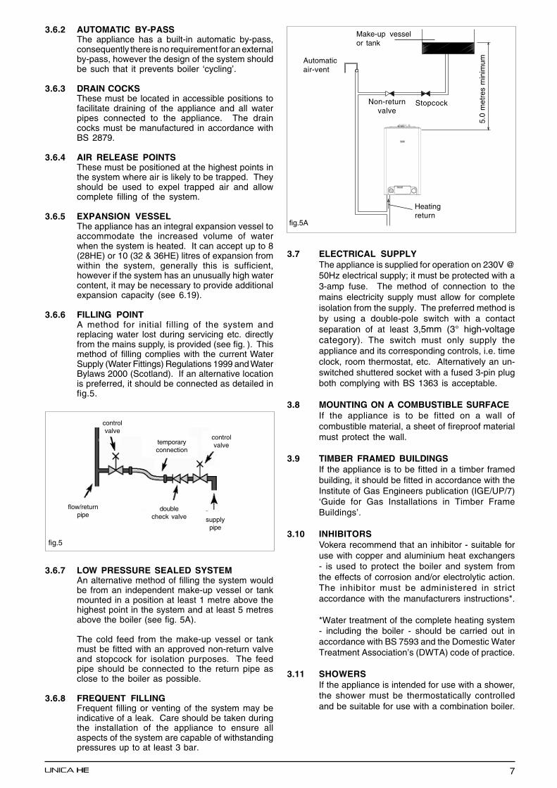
3.6.6 FILLING POINTA method for initial filling of the system andreplacing water lost during servicing etc. directlyfrom the mains supply, is provided (see fig. ). Thismethod of filling complies with the current WaterSupply (Water Fittings) Regulations 1999 and WaterBylaws 2000 (Scotland). If an alternative locationis preferred, it should be connected as detailed infig.5.
3.6.7 LOW PRESSURE SEALED SYSTEMAn alternative method of filling the system wouldbe from an independent make-up vessel or tankmounted in a position at least 1 metre above thehighest point in the system and at least 5 metresabove the boiler (see fig. 5A).
The cold feed from the make-up vessel or tankmust be fitted with an approved non-return valveand stopcock for isolation purposes. The feedpipe should be connected to the return pipe asclose to the boiler as possible.
3.6.8 FREQUENT FILLINGFrequent filling or venting of the system may beindicative of a leak. Care should be taken duringthe installation of the appliance to ensure allaspects of the system are capable of withstandingpressures up to at least 3 bar.
3.7 ELECTRICAL SUPPLYThe appliance is supplied for operation on 230V @50Hz electrical supply; it must be protected with a3-amp fuse. The method of connection to themains electricity supply must allow for completeisolation from the supply. The preferred method isby using a double-pole switch with a contactseparation of at least 3,5mm (3° high-voltagecategory). The switch must only supply theappliance and its corresponding controls, i.e. timeclock, room thermostat, etc. Alternatively an un-switched shuttered socket with a fused 3-pin plugboth complying with BS 1363 is acceptable.
3.8 MOUNTING ON A COMBUSTIBLE SURFACEIf the appliance is to be fitted on a wall ofcombustible material, a sheet of fireproof materialmust protect the wall.
3.9 TIMBER FRAMED BUILDINGSIf the appliance is to be fitted in a timber framedbuilding, it should be fitted in accordance with theInstitute of Gas Engineers publication (IGE/UP/7)‘Guide for Gas Installations in Timber FrameBuildings’.
3.10 INHIBITORSVokera recommend that an inhibitor - suitable foruse with copper and aluminium heat exchangers- is used to protect the boiler and system fromthe effects of corrosion and/or electrolytic action.The inhibitor must be administered in strictaccordance with the manufacturers instructions*.
*Water treatment of the complete heating system- including the boiler - should be carried out inaccordance with BS 7593 and the Domestic WaterTreatment Association’s (DWTA) code of practice.
3.11 SHOWERSIf the appliance is intended for use with a shower,the shower must be thermostatically controlledand be suitable for use with a combination boiler.
fig.5
flow/returnpipe
controlvalve
temporaryconnection
controlvalve
supplypipe
doublecheck valve
fig.5A
Make-up vesselor tank
Automaticair-vent
Non-returnvalve
Stopcock
5.0
met
res
min
imum
Heatingreturn
8
SECTION 3A GENERAL REQUIREMENTS (EIRE)
This appliance must be installed by a competent personin accordance with and defined by, the StandardSpecification (Domestic Gas Installations)Declaration (I.S. 813).
3A.1 RELATED DOCUMENTSThe installation of this boiler must be in accordancewith the relevant requirements of the local buildingregulations, the current ETCI National Rules forElectrical Installations, and the bylaws of the localwater undertaking.It should be in accordance also with any relevantrequirements of the local and/or district authority.
3A.2 LOCATION OF APPLIANCEThe appliance may be installed in any room orinternal space, although particular attention isdrawn to the requirements of the current ETCINational Rules for Electrical Installations, and I.S.813, Annex K.When an appliance is installed in a room or internalspace containing a bath or shower, the applianceor any control pertaining to it must not be withinreach of a person using the bath or shower.The location chosen for the appliance must permitthe provision of a safe and satisfactory flue andtermination. The location must also permit anadequate air supply for combustion purposes andan adequate space for servicing and air circulationaround the appliance. Where the installation of theappliance will be in an unusual location specialprocedures may be necessary, refer to I.S. 813 fordetailed guidance on this aspect.
A compartment used to enclose the appliancemust be designed and constructed specifically forthis purpose. An existing compartment/cupboardmay be utilised provided that it is modified to suit.
This appliance is not suitable for externalinstallation.
3A.3 GAS SUPPLYThe gas meter – as supplied by the gas supplier –must be checked to ensure that it is of adequatesize to deal with the maximum rated input of all theappliances that it serves. Installation pipes mustbe fitted in accordance with I.S. 813.
Pipe work from the meter to the appliance mustbe of adequate size. Pipes of a smaller size thanthe appliance gas inlet connection must not beused. The installation must be tested forsoundness in accordance with I.S. 813.
If the gas supply serves more than one appliance,it must be ensured that an adequate supply ismaintained to each appliance when they are inuse at the same time.
3A.4 FLUE SYSTEMThe terminal should be located where the dispersalof combustion products is not impeded and withdue regard for the damage and discoloration thatmay occur to building products located nearby.The terminal must not be located in a place whereit is likely to cause a nuisance (see I.S. 813).In cold and/or humid weather, water vapour willcondense on leaving the terminal; the effect of
such pluming must be considered.If installed less than 2m above a pavement orplatform to which people have access (includingbalconies or flat roofs) the terminal must beprotected by a guard of durable material. Theguard must be fitted centrally over the terminal.Refer to I.S. 813, when the terminal is 0.5 metres(or less) below plastic guttering or 1 metre (or less)below painted eaves.
3A.5 AIR SUPPLYThe following notes are intended for generalguidance only.This appliance is a room-sealed, fan-flued boiler,consequently it does not require a permanent airvent for combustion air supply.
When installed in a cupboard or compartment,ventilation for cooling purposes is also not required.
3A.6 WATER CIRCULATIONSpecific recommendations are given in I.S. 813.The following notes are for general guidance only.
3A.6.1 PIPEWORKIt is recommended that copper tubing be used inconjunction with soldered capillary joints.Where possible pipes should have a gradient toensure air is carried naturally to air release pointsand that water flows naturally to drain cocks.Except where providing useful heat, pipes shouldbe insulated to avoid heat loss and in particular toavoid the possibility of freezing. Particular attentionshould be paid to pipes passing through ventilatedareas such as under floors, loft space, and voidareas.
3A.6.2 AUTOMATIC BY-PASSThe appliance has a built-in automatic by-pass,consequently there is no requirement for an externalby-pass, however the design of the system shouldbe such that it prevents boiler ‘cycling’.
3A.6.3 DRAIN COCKSThese must be located in accessible positions tofacilitate draining of the appliance and all waterpipes connected to the appliance.
3A.6.4 AIR RELEASE POINTSThese must be positioned at the highest points inthe system where air is likely to be trapped. Theyshould be used to expel trapped air and allowcomplete filling of the system.
3A.6.5 EXPANSION VESSELThe appliance has an integral expansion vessel toaccommodate the increased volume of waterwhen the system is heated. It can accept up to 8(28HE) or 10 (32 & 36HE) litres of expansion fromwithin the system, generally this is sufficient,however if the system has an unusually high watercontent, it may be necessary to provide additionalexpansion capacity (see 6.19).
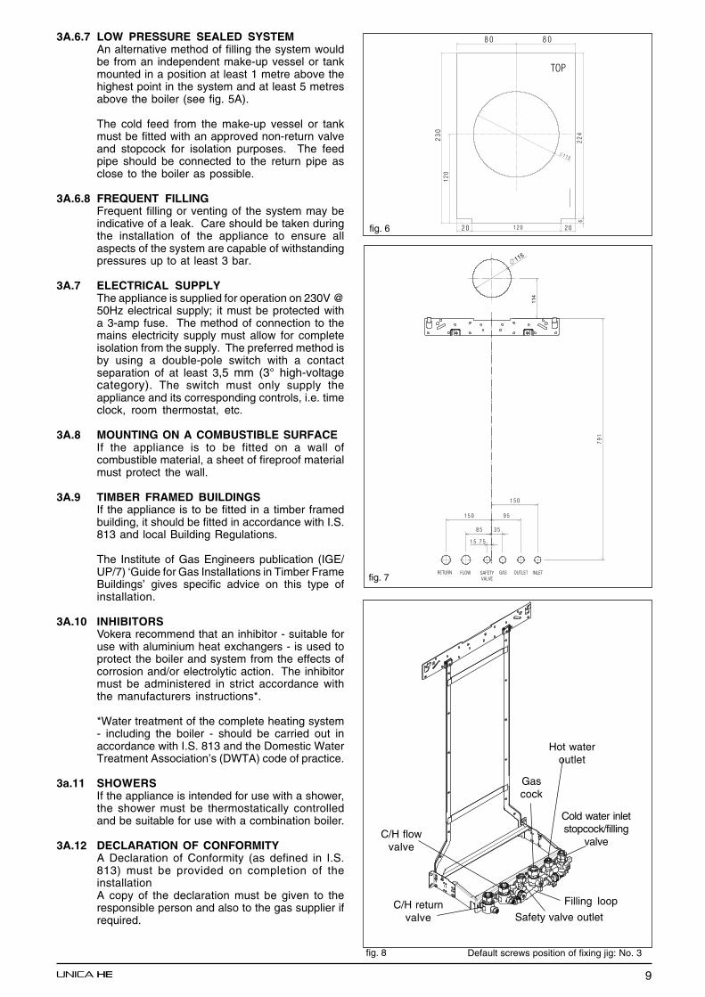
3A.6.6 FILLING POINTA method for initial filling of the system andreplacing water lost during servicing etc. is provided(see fig.8). You should ensure this method of fillingcomplies with the local water authority regulations.
9
fig. 6
3A.6.7 LOW PRESSURE SEALED SYSTEMAn alternative method of filling the system wouldbe from an independent make-up vessel or tankmounted in a position at least 1 metre above thehighest point in the system and at least 5 metresabove the boiler (see fig. 5A).
The cold feed from the make-up vessel or tankmust be fitted with an approved non-return valveand stopcock for isolation purposes. The feedpipe should be connected to the return pipe asclose to the boiler as possible.
3A.6.8 FREQUENT FILLINGFrequent filling or venting of the system may beindicative of a leak. Care should be taken duringthe installation of the appliance to ensure allaspects of the system are capable of withstandingpressures up to at least 3 bar.
3A.7 ELECTRICAL SUPPLYThe appliance is supplied for operation on 230V @50Hz electrical supply; it must be protected witha 3-amp fuse. The method of connection to themains electricity supply must allow for completeisolation from the supply. The preferred method isby using a double-pole switch with a contactseparation of at least 3,5 mm (3° high-voltagecategory). The switch must only supply theappliance and its corresponding controls, i.e. timeclock, room thermostat, etc.
3A.8 MOUNTING ON A COMBUSTIBLE SURFACEIf the appliance is to be fitted on a wall ofcombustible material, a sheet of fireproof materialmust protect the wall.
3A.9 TIMBER FRAMED BUILDINGSIf the appliance is to be fitted in a timber framedbuilding, it should be fitted in accordance with I.S.813 and local Building Regulations.
The Institute of Gas Engineers publication (IGE/UP/7) ‘Guide for Gas Installations in Timber FrameBuildings’ gives specific advice on this type ofinstallation.
3A.10 INHIBITORSVokera recommend that an inhibitor - suitable foruse with aluminium heat exchangers - is used toprotect the boiler and system from the effects ofcorrosion and/or electrolytic action. The inhibitormust be administered in strict accordance withthe manufacturers instructions*.
*Water treatment of the complete heating system- including the boiler - should be carried out inaccordance with I.S. 813 and the Domestic WaterTreatment Association’s (DWTA) code of practice.
3a.11 SHOWERSIf the appliance is intended for use with a shower,the shower must be thermostatically controlledand be suitable for use with a combination boiler.
3A.12 DECLARATION OF CONFORMITYA Declaration of Conformity (as defined in I.S.813) must be provided on completion of theinstallationA copy of the declaration must be given to theresponsible person and also to the gas supplier ifrequired.
���
���
Hot wateroutlet
Cold water inletstopcock/filling
valve
Gascock
Filling loop
C/H flowvalve
C/H returnvalve Safety valve outlet
fig. 7
fig. 8 Default screws position of fixing jig: No. 3
10
SECTION 4 INSTALLATION
Fig. 9
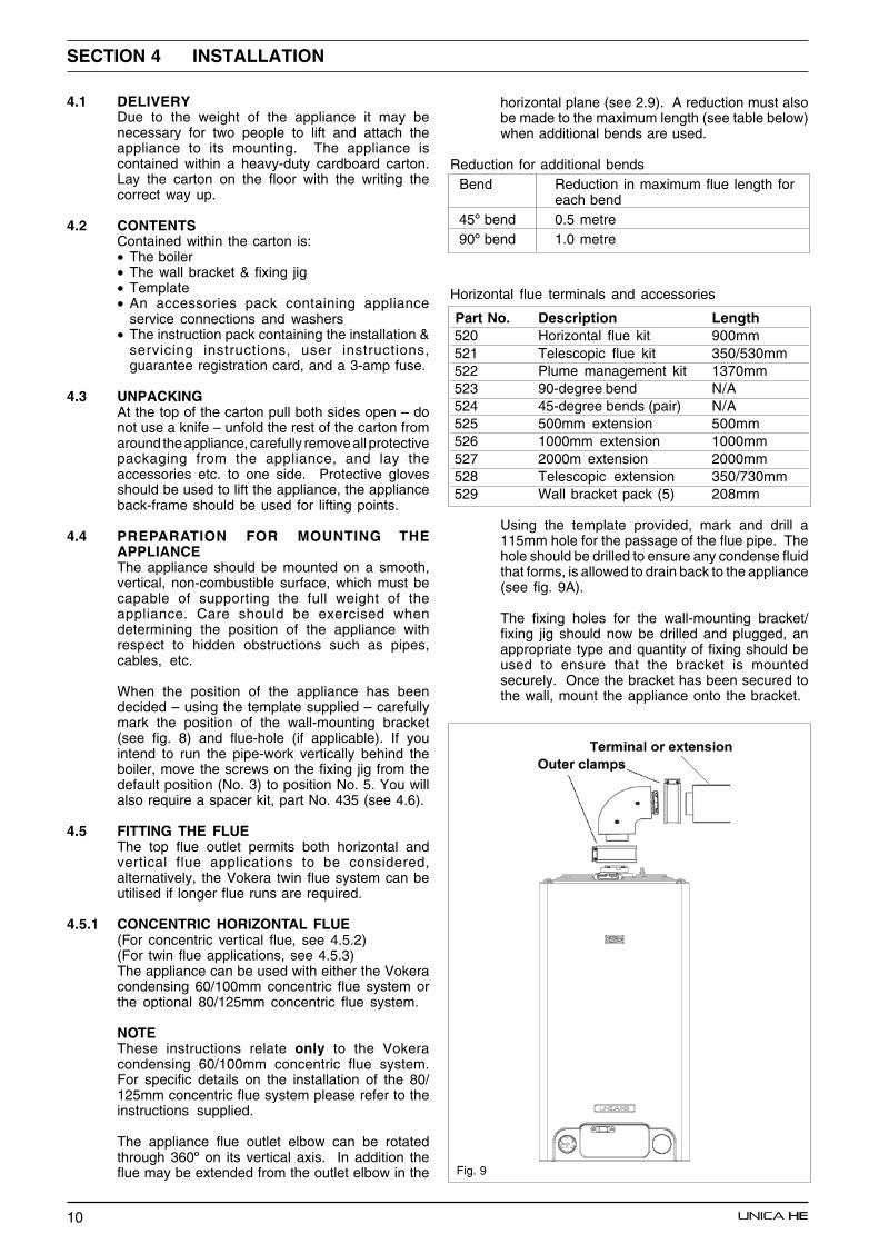
4.1 DELIVERYDue to the weight of the appliance it may benecessary for two people to lift and attach theappliance to its mounting. The appliance iscontained within a heavy-duty cardboard carton.Lay the carton on the floor with the writing thecorrect way up.
4.2 CONTENTSContained within the carton is:• The boiler• The wall bracket & fixing jig• Template• An accessories pack containing appliance
service connections and washers• The instruction pack containing the installation &
servicing instructions, user instructions,guarantee registration card, and a 3-amp fuse.
4.3 UNPACKINGAt the top of the carton pull both sides open – donot use a knife – unfold the rest of the carton fromaround the appliance, carefully remove all protectivepackaging from the appliance, and lay theaccessories etc. to one side. Protective glovesshould be used to lift the appliance, the applianceback-frame should be used for lifting points.
4.4 PREPARATION FOR MOUNTING THEAPPLIANCEThe appliance should be mounted on a smooth,vertical, non-combustible surface, which must becapable of supporting the full weight of theappliance. Care should be exercised whendetermining the position of the appliance withrespect to hidden obstructions such as pipes,cables, etc.
When the position of the appliance has beendecided – using the template supplied – carefullymark the position of the wall-mounting bracket(see fig. 8) and flue-hole (if applicable). If youintend to run the pipe-work vertically behind theboiler, move the screws on the fixing jig from thedefault position (No. 3) to position No. 5. You willalso require a spacer kit, part No. 435 (see 4.6).
4.5 FITTING THE FLUEThe top flue outlet permits both horizontal andvertical flue applications to be considered,alternatively, the Vokera twin flue system can beutilised if longer flue runs are required.
4.5.1 CONCENTRIC HORIZONTAL FLUE(For concentric vertical flue, see 4.5.2)(For twin flue applications, see 4.5.3)The appliance can be used with either the Vokeracondensing 60/100mm concentric flue system orthe optional 80/125mm concentric flue system.
NOTEThese instructions relate only to the Vokeracondensing 60/100mm concentric flue system.For specific details on the installation of the 80/125mm concentric flue system please refer to theinstructions supplied.
The appliance flue outlet elbow can be rotatedthrough 360º on its vertical axis. In addition theflue may be extended from the outlet elbow in the
horizontal plane (see 2.9). A reduction must alsobe made to the maximum length (see table below)when additional bends are used.
Reduction for additional bends Bend Reduction in maximum flue length for
each bend 45º bend 0.5 metre 90º bend 1.0 metre
Horizontal flue terminals and accessories
Part No. Description Length 520 Horizontal flue kit 900mm 521 Telescopic flue kit 350/530mm 522 Plume management kit 1370mm 523 90-degree bend N/A 524 45-degree bends (pair) N/A 525 500mm extension 500mm 526 1000mm extension 1000mm 527 2000m extension 2000mm 528 Telescopic extension 350/730mm 529 Wall bracket pack (5) 208mm
Using the template provided, mark and drill a115mm hole for the passage of the flue pipe. Thehole should be drilled to ensure any condense fluidthat forms, is allowed to drain back to the appliance(see fig. 9A).
The fixing holes for the wall-mounting bracket/fixing jig should now be drilled and plugged, anappropriate type and quantity of fixing should beused to ensure that the bracket is mountedsecurely. Once the bracket has been secured tothe wall, mount the appliance onto the bracket.
11
Fig. 9A
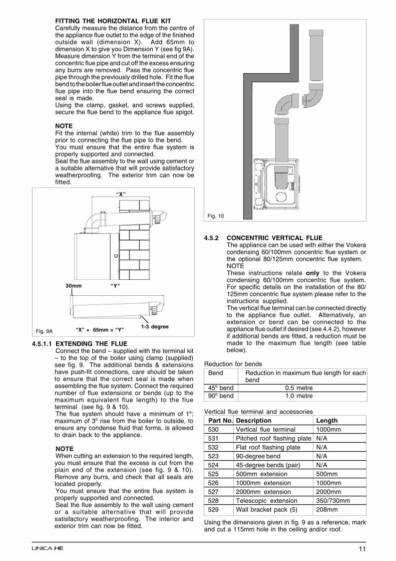
FITTING THE HORIZONTAL FLUE KITCarefully measure the distance from the centre ofthe appliance flue outlet to the edge of the finishedoutside wall (dimension X). Add 65mm todimension X to give you Dimension Y (see fig 9A).Measure dimension Y from the terminal end of theconcentric flue pipe and cut off the excess ensuringany burrs are removed. Pass the concentric fluepipe through the previously drilled hole. Fit the fluebend to the boiler flue outlet and insert the concentricflue pipe into the flue bend ensuring the correctseal is made.Using the clamp, gasket, and screws supplied,secure the flue bend to the appliance flue spigot.
NOTEFit the internal (white) trim to the flue assemblyprior to connecting the flue pipe to the bend.You must ensure that the entire flue system isproperly supported and connected.Seal the flue assembly to the wall using cement ora suitable alternative that will provide satisfactoryweatherproofing. The exterior trim can now befitted.
4.5.1.1 EXTENDING THE FLUEConnect the bend – supplied with the terminal kit– to the top of the boiler using clamp (supplied)see fig. 9. The additional bends & extensionshave push-fit connections, care should be takento ensure that the correct seal is made whenassembling the flue system. Connect the requirednumber of flue extensions or bends (up to themaximum equivalent flue length) to the flueterminal (see fig. 9 & 10).The flue system should have a minimum of 1º;maximum of 3º rise from the boiler to outside, toensure any condense fluid that forms, is allowedto drain back to the appliance.
NOTEWhen cutting an extension to the required length,you must ensure that the excess is cut from theplain end of the extension (see fig. 9 & 10).Remove any burrs, and check that all seals arelocated properly.You must ensure that the entire flue system isproperly supported and connected.Seal the flue assembly to the wall using cementor a suitable alternative that will providesatisfactory weatherproofing. The interior andexterior trim can now be fitted.
4.5.2 CONCENTRIC VERTICAL FLUEThe appliance can be used with either the Vokeracondensing 60/100mm concentric flue system orthe optional 80/125mm concentric flue system.NOTEThese instructions relate only to the Vokeracondensing 60/100mm concentric flue system.For specific details on the installation of the 80/125mm concentric flue system please refer to theinstructions supplied.The vertical flue terminal can be connected directlyto the appliance flue outlet. Alternatively, anextension or bend can be connected to theappliance flue outlet if desired (see 4.4.2), howeverif additional bends are fitted, a reduction must bemade to the maximum flue length (see tablebelow).
Reduction for bends Bend Reduction in maximum flue length for each
bend 45º bend 0.5 metre 90º bend 1.0 metre
Vertical flue terminal and accessories Part No. Description Length 530 Vertical flue terminal 1000mm 531 Pitched roof flashing plate N/A 532 Flat roof flashing plate N/A 523 90-degree bend N/A 524 45-degree bends (pair) N/A 525 500mm extension 500mm 526 1000mm extension 1000mm 527 2000mm extension 2000mm 528 Telescopic extension 350/730mm 529 Wall bracket pack (5) 208mm
Using the dimensions given in fig. 9 as a reference, markand cut a 115mm hole in the ceiling and/or roof.
“X”
“Y”30mm
1-3 degree“X” + 65mm = “Y”
Fig. 10

12
Fig. 11
Fit the appropriate flashing plate to the roof andinsert the vertical flue terminal through the flashingplate from the outside, ensuring that the collar onthe flue terminal fits over the flashing.The fixing holes for the wall-mounting bracket/fixing jig should now be drilled and plugged, anappropriate type and quantity of fixing should beused to ensure that the bracket is mountedsecurely. Once the bracket has been secured tothe wall, mount the appliance onto the bracket.
IMPORTANTThe vertical flue terminal is 1.0 metre in length andcannot be cut; therefore it may be necessary toadjust the height of the appliance to suit or use asuitable extension.
Connect the vertical flue assembly to the boilerflue spigot using the 100mm clip, gasket, &screws (supplied), ensuring the correct seal ismade. The flue support bracket (supplied with thevertical flue kit) can now be fitted.
If the vertical flue requires extension/s or additionalbend/s, connect the required number of flueextensions or bends (up to the maximum equivalentflue length) between the boiler and vertical flueassembly (see fig. 10).
Ensure that any horizontal sections of the fluesystem have a minimum 1º; maximum 3º fall backto the boiler (1º = 17mm per 1000mm)
NOTEWhen cutting an extension to the required length,you must ensure that the excess is cut from theplain end of the extension (see fig. 8). Removeany burrs, and check that any seals are locatedproperly.
You must ensure that the entire flue system isproperly supported and connected.
4.5.3 TWIN FLUE SYSTEMThe Vokera twin flue system enables greater fluedistances to be achieved (see 4.4.2) than that ofa concentric flue system. It can be used forhorizontal or vertical applications, however thetwin flue system must be converted to the dedicatedconcentric flue kit for termination. It is essentialthat the installation of the twin flue system becarried out in strict accordance with theseinstructions.
GUIDANCE NOTES ON TWIN FLUEINSTALLATION• The flue must have a have a minimum 1º;
maximum 3º (1º = 17mm per 1000mm) fall backto the appliance to allow any condensate thatmay form in the flue system to drain via thecondensate drain. Consideration must also begiven to the fact that there is the possibility of asmall amount of condensate dripping from theterminal.
• Ensure that the entire flue system is adequatelysupported, use at least one bracket for eachextension.
• The entire flue system must be adequatelyinsulated to maintain heat within the flue systemthereby reducing the possibility of condensateproduction.
• As the exhaust outlet pipe can reach very hightemperatures it must be protected to preventpersons touching the hot surface.
• The condensate drain pipe must be connected inaccordance with building regulations
Reduction for bends Bend Reduction in maximum flue length for
each bend 45º bend 1.0 metre 90º bend 1.0 metre
Twin flue accessories Part No. Description Length 0225805 Horizontal flue terminal 1.0 metre 0225810 Vertical flue terminal 1.0 metre 359 Twin adapter kit N/A 531 Pitched roof flashing plate N/A 532 Flat roof flashing plate N/A 0225815 Condensate drain kit N/A 0225820 0.25m extension (pair) 250mm 0225825 0.5m extension (pair) 500mm 0225830 1.0m extension (pair) 1000mm 0225835 2.0m extension (pair) 2000mm 0225840 45º bend (pair) N/A 0225845 90º bend (pair) N/A 0225850 Twin bracket (5) N/A 0225855 Single bracket (5) N/A
MOUNTING THE BOILERThe fixing holes for the wall-mounting bracketshould now be drilled and plugged, an appropriatetype and quantity of fixing should be used toensure that the bracket is mounted securely.Once the bracket has been secured to the wall,mount the appliance onto the bracket.
4.5.3.1 INSTALLATION OF TWIN ADAPTOR KIT (fig. 12& 13)• Insert the exhaust connection manifold (A) onto
the appliance flue outlet.• Remove the blanking plate (located to the right
of the appliance flue outlet) and – using the same
“X”12/15/20HE = 202mm25/30/35HE = 218mm
“X”28/32/36 HE = 218 mm

13
screws – install the air inlet plate (B).• Using the hole in the exhaust connection manifold
as a guide, drill a 3mm hole in the appliance fluespigot and secure the exhaust manifoldconnection to the flue spigot using the screwprovided (C).
• Using the two holes in the air inlet plate as aguide, drill a 3mm hole in each and secure the airinlet pipe/bend using the screws provided.
The twin flue pipes extensions and accessoriescan now be installed by pushing together (the plainend of each extension or bend should be pushedapproximately 50mm into the female socket of theprevious piece).
Fig. 12
4.5.3.2 HORIZONTAL TERMINATION(See fig. 14)The twin flue system must be converted to thededicated concentric flue kit for termination.• The horizontal terminal is supplied with a built-
in converter box and cannot be shortened.• A 130mm hole is required for the passage of the
concentric terminal through the wall.• The air inlet pipe must always be level with or
below, that of the exhaust pipe.
Depending on site conditions it may be preferableto install the terminal assembly prior to fitting thetwin flue pipes.
Mark and drill a level 130mm hole for the passageof the horizontal flue terminal. Insert the terminalassembly into the flue hole.Push-fit the twin flue pipes onto the concentric totwin converter box ensuring that the exhaust pipe
connects to the exhaust connection on theconcentric to twin converter.
If necessary cut the plain ends (male) of the twinflue pipes to allow connection to the concentric totwin converter.
NOTE; before cutting twin flue pipes ensureallowances have been made for connection ontothe previous piece and onto the concentric to twinconverter. The last twin Flue pipes must bepushed 50mm onto the male spigots of theconcentric to twin converter.
NOTE;Seal the flue terminal assembly to the wall usingcement or a suitable alternative that will providesatisfactory weatherproofing. The interior andexterior trim can now be fitted.
4.5.3.3 VERTICAL TERMINATION(See fig. 15)The twin flue system must be converted to thededicated concentric flue kit for termination.• The vertical terminal is supplied with a built-in
converter box and cannot be shortened.• A 130mm hole is required for the passage of the
concentric terminal through the ceiling and/orroof.
Depending on site conditions it may be preferableto install the terminal assembly prior to fitting thetwin flue pipes.
Fit the appropriate flashing plate to the roof andinsert the vertical flue terminal through the flashingplate from the outside, ensuring that the collar onthe flue terminal fits over the flashing.
Push-fit the twin flue pipes onto the concentric totwin converter ensuring that the exhaust pipeconnects to the exhaust connection on theconcentric to twin converter.If necessary cut the plain ends (male) of the twinflue pipes to allow connection to the concentric totwin converter.
NOTE• Before cutting twin flue pipes ensure allowances
have been made for connection onto the previouspiece and onto the concentric to twin converter.The last twin flue pipes must be pushed 50mmonto the male spigots of the concentric to twinconverter.
• You must ensure that the entire flue system isproperly supported and connected.
• Ensure that any horizontal sections of pipe havea 1º fall towards the appliance (17mm per1000mm).
B
C
A
Fig. 13
14
Fig. 14
Fig. 15
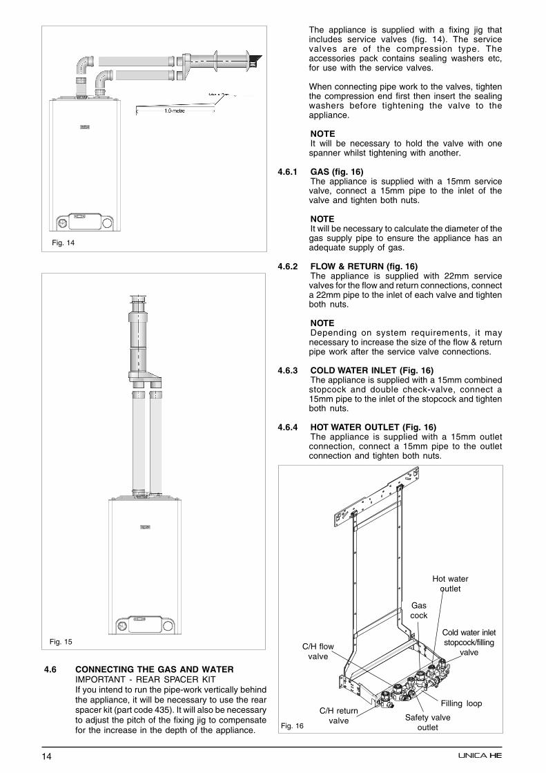
4.6 CONNECTING THE GAS AND WATERIMPORTANT - REAR SPACER KITIf you intend to run the pipe-work vertically behindthe appliance, it will be necessary to use the rearspacer kit (part code 435). It will also be necessaryto adjust the pitch of the fixing jig to compensatefor the increase in the depth of the appliance.
The appliance is supplied with a fixing jig thatincludes service valves (fig. 14). The servicevalves are of the compression type. Theaccessories pack contains sealing washers etc,for use with the service valves.
When connecting pipe work to the valves, tightenthe compression end first then insert the sealingwashers before tightening the valve to theappliance.
NOTEIt will be necessary to hold the valve with onespanner whilst tightening with another.
4.6.1 GAS (fig. 16)The appliance is supplied with a 15mm servicevalve, connect a 15mm pipe to the inlet of thevalve and tighten both nuts.
NOTEIt will be necessary to calculate the diameter of thegas supply pipe to ensure the appliance has anadequate supply of gas.
4.6.2 FLOW & RETURN (fig. 16)The appliance is supplied with 22mm servicevalves for the flow and return connections, connecta 22mm pipe to the inlet of each valve and tightenboth nuts.
NOTEDepending on system requirements, it maynecessary to increase the size of the flow & returnpipe work after the service valve connections.
4.6.3 COLD WATER INLET (Fig. 16)The appliance is supplied with a 15mm combinedstopcock and double check-valve, connect a15mm pipe to the inlet of the stopcock and tightenboth nuts.
4.6.4 HOT WATER OUTLET (Fig. 16)The appliance is supplied with a 15mm outletconnection, connect a 15mm pipe to the outletconnection and tighten both nuts.
Fig. 16
Hot wateroutlet
Cold water inletstopcock/filling
valve
Gascock
Filling loop
C/H flowvalve
C/H returnvalve Safety valve
outlet
15
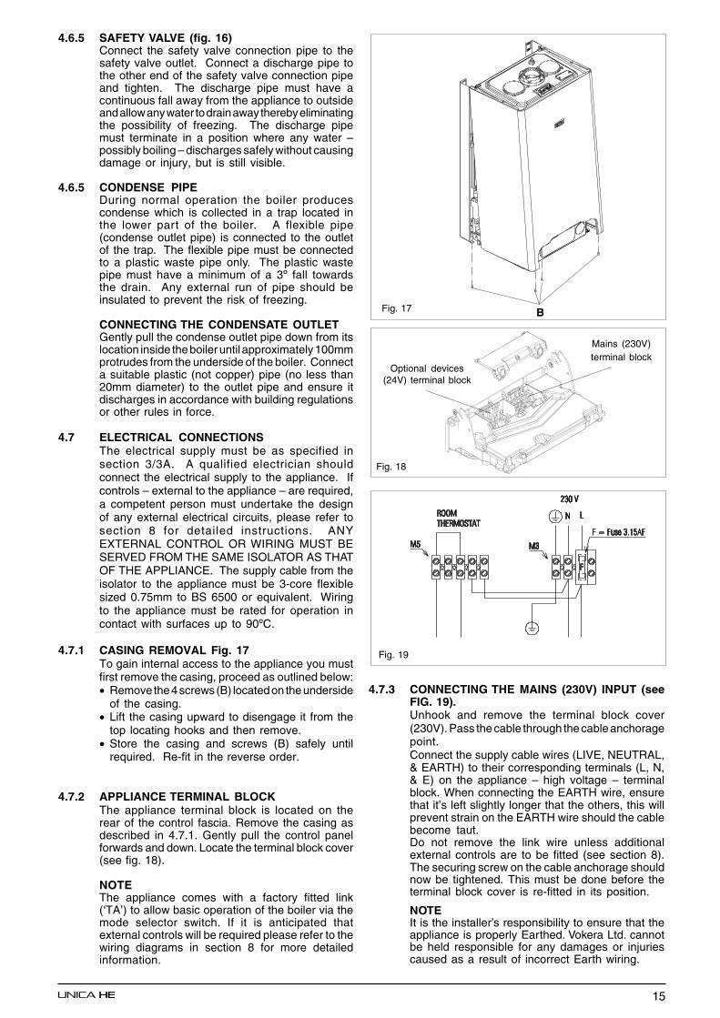
4.6.5 SAFETY VALVE (fig. 16)Connect the safety valve connection pipe to thesafety valve outlet. Connect a discharge pipe tothe other end of the safety valve connection pipeand tighten. The discharge pipe must have acontinuous fall away from the appliance to outsideand allow any water to drain away thereby eliminatingthe possibility of freezing. The discharge pipemust terminate in a position where any water –possibly boiling – discharges safely without causingdamage or injury, but is still visible.
4.6.5 CONDENSE PIPEDuring normal operation the boiler producescondense which is collected in a trap located inthe lower part of the boiler. A flexible pipe(condense outlet pipe) is connected to the outletof the trap. The flexible pipe must be connectedto a plastic waste pipe only. The plastic wastepipe must have a minimum of a 3º fall towardsthe drain. Any external run of pipe should beinsulated to prevent the risk of freezing.
CONNECTING THE CONDENSATE OUTLETGently pull the condense outlet pipe down from itslocation inside the boiler until approximately 100mmprotrudes from the underside of the boiler. Connecta suitable plastic (not copper) pipe (no less than20mm diameter) to the outlet pipe and ensure itdischarges in accordance with building regulationsor other rules in force.
4.7 ELECTRICAL CONNECTIONSThe electrical supply must be as specified insection 3/3A. A qualified electrician shouldconnect the electrical supply to the appliance. Ifcontrols – external to the appliance – are required,a competent person must undertake the designof any external electrical circuits, please refer tosection 8 for detailed instructions. ANYEXTERNAL CONTROL OR WIRING MUST BESERVED FROM THE SAME ISOLATOR AS THATOF THE APPLIANCE. The supply cable from theisolator to the appliance must be 3-core flexiblesized 0.75mm to BS 6500 or equivalent. Wiringto the appliance must be rated for operation incontact with surfaces up to 90ºC.
4.7.1 CASING REMOVAL Fig. 17To gain internal access to the appliance you mustfirst remove the casing, proceed as outlined below:• Remove the 4 screws (B) located on the underside
of the casing.• Lift the casing upward to disengage it from the
top locating hooks and then remove.• Store the casing and screws (B) safely until
required. Re-fit in the reverse order.
4.7.2 APPLIANCE TERMINAL BLOCKThe appliance terminal block is located on therear of the control fascia. Remove the casing asdescribed in 4.7.1. Gently pull the control panelforwards and down. Locate the terminal block cover(see fig. 18).
NOTEThe appliance comes with a factory fitted link(‘TA’) to allow basic operation of the boiler via themode selector switch. If it is anticipated thatexternal controls will be required please refer to thewiring diagrams in section 8 for more detailedinformation.
Fig. 17
Fig. 18
B
Optional devices(24V) terminal block
Mains (230V)terminal block
Fig. 19
4.7.3 CONNECTING THE MAINS (230V) INPUT (seeFIG. 19).Unhook and remove the terminal block cover(230V). Pass the cable through the cable anchoragepoint.Connect the supply cable wires (LIVE, NEUTRAL,& EARTH) to their corresponding terminals (L, N,& E) on the appliance – high voltage – terminalblock. When connecting the EARTH wire, ensurethat it’s left slightly longer that the others, this willprevent strain on the EARTH wire should the cablebecome taut.Do not remove the link wire unless additionalexternal controls are to be fitted (see section 8).The securing screw on the cable anchorage shouldnow be tightened. This must be done before theterminal block cover is re-fitted in its position.
NOTEIt is the installer’s responsibility to ensure that theappliance is properly Earthed. Vokera Ltd. cannotbe held responsible for any damages or injuriescaused as a result of incorrect Earth wiring.
16
SECTION 5 COMMISSIONING
5.1 GAS SUPPLY INSTALLATIONInspect the entire installation including the gasmeter, test for soundness and purge. Refer to BS6891 (I.S. 813 in ROI) for specific instruction.
5.2 THE HEATING SYSTEMThe appliance contains components that maybecome damaged or rendered inoperable by oilsand/or debris that are residual from the installationof the system, consequently it is essential thatthe system be flushed in accordance with thefollowing instructions.
5.3 INITIAL FILLING OF THE SYSTEMEnsure both flow and return service valves areopen, remove appliance casing as described in4.7.1, identify the automatic air release valves(AAV) and loosen the dust cap/s by turning the capanti-clockwise one full turn.Ensure all manual air release valves located onthe heating system are closed. Connect the fillingloop as shown in fig. 5, slowly proceed to fill thesystem by firstly opening the inlet valve connectedto the flow pipe, and then turning the lever on thefill valve, to the open position. As water enters thesystem the pressure gauge will begin to rise. Oncethe gauge has reached 1 BAR close both valvesand begin venting all manual air release valves,starting at the lowest first. It may be necessary togo back and top-up the pressure until the entiresystem has been filled. Inspect the system forwater soundness, rectifying any leaks.
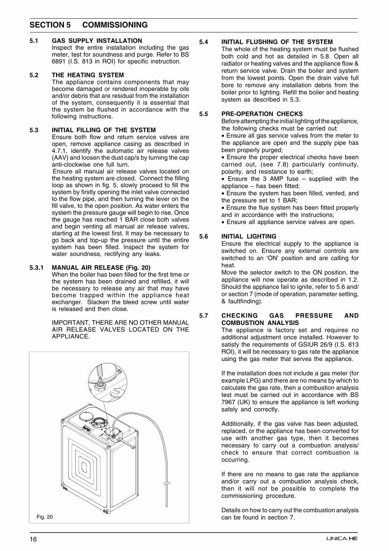
5.3.1 MANUAL AIR RELEASE (Fig. 20)When the boiler has been filled for the first time orthe system has been drained and refilled, it willbe necessary to release any air that may havebecome trapped within the appliance heatexchanger. Slacken the bleed screw until wateris released and then close.
IMPORTANT, THERE ARE NO OTHER MANUALAIR RELEASE VALVES LOCATED ON THEAPPLIANCE.
Fig. 20
5.4 INITIAL FLUSHING OF THE SYSTEMThe whole of the heating system must be flushedboth cold and hot as detailed in 5.8. Open allradiator or heating valves and the appliance flow &return service valve. Drain the boiler and systemfrom the lowest points. Open the drain valve fullbore to remove any installation debris from theboiler prior to lighting. Refill the boiler and heatingsystem as described in 5.3.
5.5 PRE-OPERATION CHECKSBefore attempting the initial lighting of the appliance,the following checks must be carried out:• Ensure all gas service valves from the meter tothe appliance are open and the supply pipe hasbeen properly purged;• Ensure the proper electrical checks have beencarried out, (see 7.8) particularly continuity,polarity, and resistance to earth;• Ensure the 3 AMP fuse – supplied with theappliance – has been fitted;• Ensure the system has been filled, vented, andthe pressure set to 1 BAR;• Ensure the flue system has been fitted properlyand in accordance with the instructions;• Ensure all appliance service valves are open.
5.6 INITIAL LIGHTINGEnsure the electrical supply to the appliance isswitched on. Ensure any external controls areswitched to an ‘ON’ position and are calling forheat.Move the selector switch to the ON position, theappliance will now operate as described in 1.2.Should the appliance fail to ignite, refer to 5.6 and/or section 7 (mode of operation, parameter setting,& faultfinding).
5.7 CHECKING GAS PRESSURE ANDCOMBUSTION ANALYSISThe appliance is factory set and requires noadditional adjustment once installed. However tosatisfy the requirements of GSIUR 26/9 (I.S. 813ROI), it will be necessary to gas rate the applianceusing the gas meter that serves the appliance.
If the installation does not include a gas meter (forexample LPG) and there are no means by which tocalculate the gas rate, then a combustion analysistest must be carried out in accordance with BS7967 (UK) to ensure the appliance is left workingsafely and correctly.
Additionally, if the gas valve has been adjusted,replaced, or the appliance has been converted foruse with another gas type, then it becomesnecessary to carry out a combustion analysis/check to ensure that correct combustion isoccurring.
If there are no means to gas rate the applianceand/or carry out a combustion analysis check,then it will not be possible to complete thecommissioning procedure.
Details on how to carry out the combustion analysiscan be found in section 7.
17
IMPORTANTIt’s imperative that a sufficient dynamic – gas –pressure is maintained at all times. Should thedynamic gas pressure fall below an acceptablelevel, the appliance may malfunction or sustaindamage.
5.8 FINAL FLUSHING OF THE HEATING SYSTEMThe system shall be flushed in accordance withBS 7593 (I.S. 813 ROI). Should a cleanser beused, it must be suitable for Aluminium heatexchangers. It shall be from a reputablemanufacturer and shall be administered in strictaccordance with the manufacturers’ instructionsand the DWTA code of practice.
5.8.1 INHIBITORSSee Section 3 “General Requirements”.
5.9 SETTING THE FLOW OUTLET TEMPERATUREThe flow outlet temperature can be adjustedbetween 40 °C - 80 °C for standard CH system andbetween 20 °C - 45 °C for under-floor systems byusing the Heating thermostat knob (see fig.1).
5.9.1 SETTING THE DHW OUTLET TEMPERATUREThe DHW outlet temperature can be adjustedbetween 35 °C - 60 °C via the DHW thermostatknob (see fig.1).
5.10 SETTING THE SYSTEM DESIGN PRESSUREThe design pressure should be a minimum of 0.5BAR and a maximum of 1.5 BAR. The actualreading should ideally be 1 BAR plus the equivalentheight in metres (0.1 BAR = 1 metre) to the highestpoint in the system above the base of the appliance(up to the maximum of 1.5 BAR total). N.B. Thesafety valve is set to lift at 3 BAR/30 metres/45psig. To lower the system pressure to the requiredvalue, drain off some water from the appliancedrain valve until the required figure registers on thepressure gauge (see fig. 1).
5.11 REGULATING THE CENTRAL HEATINGSYSTEMFully open all radiator and circuit valves and runthe appliance for both heating and hot water untilheated water is circulating. If conditions are warmremove any thermostatic heads. Adjust radiatorreturn valves and any branch circuit return valvesuntil the individual return temperatures are correctand are approximately equal.
5.11.1 REGULATING THE DHW FLOW-RATEThe appliance is fitted with a flow rate restrictorthat limits the maximum flow rate that can be drawnthrough the appliance.The restrictor eliminates the need to manuallyadjust the DHW flow rate. However if it is feltnecessary to further increase or decrease theavailable flow rate, spare restrictors are includedin the accessory pack.The spare flow rate restrictors can be fitted toeither increase or decrease the maximum flowrate. The tables overleaf denote the size of restrictorfitted and the spare restrictors supplied in theaccessory pack. Each restrictor is colour-codedto enable identification.
5.11.2 CHANGING THE FLOW-RATE RESTRICTORRefer to 6.27 for detailed instruction on changingthe flow restrictor.
Unica 28HE 9-litres 10-litres11-litres (Orange) (Blue) (Beige) Spare Fitted Spare
Unica 32HE 11-litres 12-litres13-litres (Beige) (Red) (Olive) Spare Fitted Spare
Unica 36HE 13-litres 14-litres15-litres (Olive) Spare Fitted spare
5.12 FINAL CHECKS• ENSURE ALL TEST NIPPLES ON THEAPPLIANCE GAS VALVE ARE TIGHT ANDCHECKED FOR SOUNDNESS.• ENSURE THE APPLIANCE FLUESYSTEM IS FITTED CORRECTLY AND ISPROPERLY SECURED.• ENSURE ALL PIPE WORK IS RE-CHECKED FOR SOUNDNESS.• RE-FIT APPLIANCE CASING.• COMPLETE BENCHMARK CHECKLIST.
FOR UK ONLYComplete details of the boiler, controls, installationand commissioning in the Benchmark checklistat the back of this book. It is important that theBenchmark checklist is correctly completed andhanded to the user. Failure to install andcommission the appliance to the manufacturersinstructions may invalidate the warranty.
5.13 INSTRUCTING THE USERHand over all documentation supplied with thisappliance – including these instructions – andexplain the importance of keeping them in a safeplace.Explain to the user how to isolate the appliancefrom the gas, water and electricity supplies, andthe locations of all drain points. Show the user howto operate the appliance and any associatedcontrols correctly.Show the user the location of the filling valve andhow to top-up the system pressure correctly andshow the location of all manual air release points.
Explain to the user how to turn off the appliancefor both long and short periods and advise on thenecessary precautions to prevent frost damage.Explain to the user that for continued safe andefficient operation, the appliance must be servicedannually by a competent person.
IMPORTANTTo validate the appliance warranty, it’s necessaryto register the appliance details with us. Thewarranty can be registered in several ways:• By completing the warranty registrationcard and posting to us using the envelope supplied• Online at: vokera.co.uk• For UK residents by calling: 0870 6070281• For ROI residents by calling: 1850221121.

18
SECTION 6 SERVICING INSTRUCTIONS
6.1 GENERALTo ensure the continued safe and efficientoperation of the appliance, it is recommended thatit is checked and serviced at regular intervals. Toensure correct and safe operation of the appliance,it is essential that any worn or failed componentbe replaced only with a genuine Vokera sparepart. It should be remembered that althoughcertain generic components may look similar, theywill be specific to an individual appliance orproduct range. Use of non-genuine Vokera spareparts could invalidate your warranty and may posea potential safety hazard. The frequency ofservicing will depend upon the par ticularinstallation conditions, but in general, once peryear should be sufficient. It is the law that anyservicing work is carried out by competent personsuch as a Vokera engineer, an approved serviceagent, British Gas,CORGI registered personnel or other suitablyqualified personnel. The following instructionsapply to the appliance and its controls, but itshould be remembered that the central heatingand the domestic hot water systems would alsorequire attention from time to time.
6.2 ROUTINE ANNUAL SERVICING• Check the operation of the appliance and ensure
it functions as described in section 7.• Compare the performance of the appliance with
its design specification. The cause of anynoticeable deterioration should be identified andrectified without delay.
• Thoroughly inspect the appliance for signs ofdamage or deterioration especially the fluesystem and the electrical apparatus.
• Check and adjust – if necessary – all burnerpressure settings (see 7.4).
• Check and adjust – if necessary – the systemdesign pressure (see 5.10).
• Carry out an analysis of the flue gases (see7.5), and visually check the condition of theentire flue assembly.
• Compare the results with the appliance designspecification. Any deterioration in performancemust be identified and rectified without delay.
• Check that the burner and main heat exchangerare clean and free from any debris or obstruction.
• Check and clean – if necessary – the condensetrap to ensure correct operation.
6.3 REPLACEMENT OF COMPONENTSAlthough it is anticipated that this appliance willgive years of reliable, trouble free service, the lifespan of components will be determined by factorssuch as operating conditions and usage. Shouldthe appliance develop a fault, the fault findingsection will assist in determining which componentis malfunctioning.
6.4 COMPONENT REMOVAL PROCEDURETo remove a component, access to the interior ofthe appliance is essential. Isolate the appliancefrom the electrical supply and remove the fuse.And when necessary, close all service valves onthe appliance, remove the appliance casing asdescribed in section 4.7.1 and drain the water
content from the appliance via the drain valve.Ensure some water absorbent cloths are availableto catch any residual water that may drip fromthe appliance or removed component. Undertakea complete commissioning check as detailed insection 5, after replacing any component.ALWAYS TEST FOR GAS SOUNDNESS IF ANYGAS CARRYING COMPONENTS HAVE BEENREMOVED OR DISTURBED.
6.4.1 AIR BOX FRONT COVER REMOVAL (fig. 21)Locate the two clips and remove air box frontcover. If it’s necessary to remove the air box sidecover, locate and remove the 4 securing screws.
6.5 PUMP ASSEMBLY (fig. 22)Carry out component removal procedure asdescribed in 6.4. Disconnect the flow pipe (B) fromthe combustion chamber connection (only 32/36HE), slacken the pipe at the hydraulic assemblyand swing/rotate clear of the pump assembly.Disconnect and remove the pump outlet pipe (C)from the pump assembly/combustion chamberconnection.
fig. 21
Remove the expansion pipe locking pin (D) fromthe top of the pump assembly and withdraw theflexible pipe. Locate and remove the pressuregauge securing pin (D1) and disconnect thepressure gauge from the pump assembly.Disconnect the electrical wiring from the pump’selectrical connection point (E). Locate and removethe 2 securing screws (A) at the rear of the pumpassembly. Remove locking pin (F) from pump baseand lift pump assembly clear of the hydraulicmanifold. The pump assembly can now be removedfrom the appliance. Replace carefully in thereverse order.
clips
fig. 22
CD1
D
EB
A
F
G
H
19
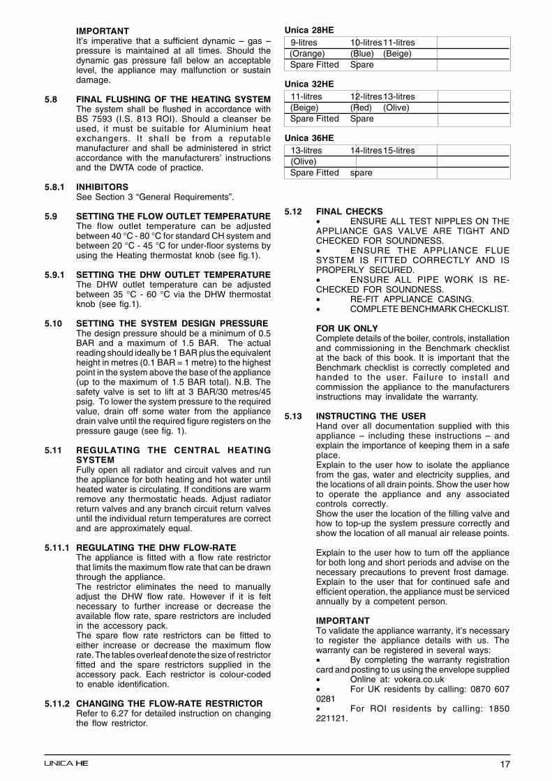
6.6 SAFETY VALVE (fig. 23)Carry out component removal procedure asdescribed in 6.4. Disconnect the outlet pipe (A)from the safety valve, remove safety valve lockingpin (B) from the hydraulic manifold. Replace in thereverse order.
6.7 LOWER AUTOMATIC AIR RELEASE VALVE(fig. 22)Carry out component removal procedure asdescribed in 6.4. Remove the expansion pipelocking pin (D) from the pump assembly andremove the expansion pipe. Locate and removethe AAV locking pin (G) from the pump assemblyand remove the AAV assembly (H). Replace inthe reverse order.
6.7.1 TOP AUTOMATIC AIR RELEASE VALVE (fig.24)Carry out component removal procedure asdescribed in 6.4.Remove the drain pipe (A). Unscrew the top AAV(B). Replace in the reverse order. Loctite or similarshould be used as a thread sealant for the AAV.
6.8 WATER PRESSURE SWITCH (fig. 23)Carry out component removal procedure asdescribed in 6.4. Locate and remove the lockingpin (C) from the water pressure switch. Removethe wiring. Carefully withdraw the switch. Replacein the reverse order.
6.9 PRIMARY THERMISTOR (fig. 1)Carry out component removal procedure asdescribed in 6.4. Unclip and remove the airchamber front cover. Unclip the primary thermistorfrom the flow outlet pipe. Disconnect thermistorelectrical plug. Replace in the reverse order.
6.10 RETURN THERMISTOR (fig. 1)Carry out component removal procedure asdescribed in 6.4. Unclip and remove the airchamber front cover. Unclip the return thermistorfrom the return inlet pipe. Disconnect thermistorelectrical plug. Replace in the reverse order.
6.11 PRINTED CIRCUIT BOARD (fig. 25)Carry out component removal procedure asdescribed in 6.4. Pull the control fascia forwardand lower it. Push the clips (A) which secure thePCB cover, remove cover, after carefully takingnote of all wiring connections and jumper tagconfiguration. Unhook and remove connectionblock (B). Disconnect all wiring from the PCB,locate and remove the PCB securing screws,remove the required PCB. Replace in the reverseorder ensuring that the position of the 3 controlknobs are correctly aligned with the respectivepotentiometers on the PCB.
Ensure that the correct jumper tag configurationhas been respected. It will be necessary to checkthe functioning of the PCB is set for the correctboiler type/application.
A
B
Fig. 24
fig. 26
6.12 GAS VALVE (fig. 26)Carry out component removal procedure asdescribed in 6.4. The gas valve must be changedas complete unit. Disconnect the electrical plugand leads from the gas valve, slacken andunscrew gas valve inlet and outlet connections.Please note, the sealing washers (B) must bediscarded and replaced with new sealing washers.Disconnect the compensation pipe (C). Locate andremove gas valve retaining screws (D) on theunderside of the boiler if required, the gas valvecan now be removed. Replace in the reverse order.Check and adjust burner pressure settings.
WARNING, A GAS SOUNDNESS CHECK MUSTBE CARRIED OUT.
Fig. 25 A
B
6.12.1 INJECTOR (fig. 26)Carry out component removal procedure asdescribed in 6.4. Unscrew and remove gas pipeconnections (A & E). Locate and remove theinjector (F) inside the pipe. Replace in the reverseorder. Check and adjust burner pressure settings.WARNING, A GAS SOUNDNESS CHECK MUSTBE CARRIED OUT.
fig. 23
B AC
A
B
DB
C
E
F
20
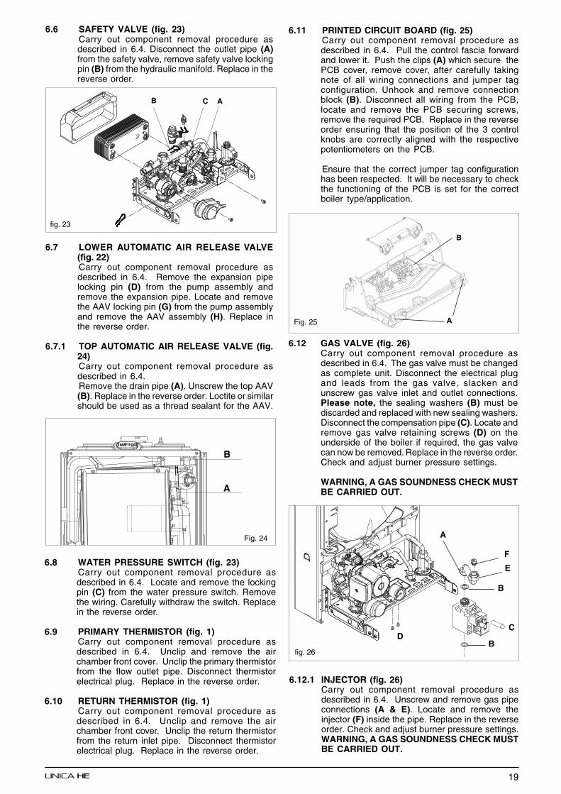
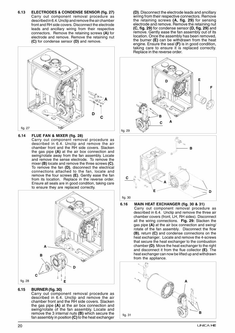
6.14 FLUE FAN & MIXER (fig. 28)Carry out component removal procedure asdescribed in 6.4. Unclip and remove the airchamber front and the RH side covers. Slackenthe gas pipe (A) at the air box connection andswing/rotate away from the fan assembly. Locateand remove the sense electrode. To remove themixer (B) locate and remove the three screws (C).To remove the fan (D), disconnect the electricalconnections attached to the fan, locate andremove the four screws (E). Gently ease the fanfrom its location. Replace in the reverse order.Ensure all seals are in good condition, taking careto ensure they are replaced correctly.
fig. 28
6.15 BURNER (fig. 30)Carry out component removal procedure asdescribed in 6.4. Unclip and remove the airchamber front and the RH side covers. Slackenthe gas pipe (A) at the air box connection andswing/rotate of the fan assembly. Locate andremove the 3 internal nuts (B) which secure thefan assembly in position (C) to the heat exchanger
fig. 30
6.16 MAIN HEAT EXCHANGER (fig. 30 & 31)Carry out component removal procedure asdescribed in 6.4. Unclip and remove the three airchamber covers (front, LH, RH sides). Disconnectall the wiring connections. Fig. 29: Slacken thegas pipe (A) at the air box connection and swing/rotate of the fan assembly. Disconnect the flow(B), return (C) and condense connections on theheat exchanger. Locate and remove the 4-screwsthat secure the heat exchanger to the combustionchamber (D). Move the heat exchanger to the rightand disconnect it from the flue collector (E). Theheat exchanger can now be lifted up and withdrawnfrom the appliance.
A
B
E
C
D
E
F
BA
D
C
fig. 29
CA
B
DE
A
CD
fig. 27
6.13 ELECTRODES & CONDENSE SENSOR (fig. 27)Carry out component removal procedure asdescribed in 6.4. Unclip and remove the air chamberfront and RH side covers. Disconnect the electrodeleads and ancillary wiring from their respectiveconnectors. Remove the retaining screws (A) forelectrode and remove. Remove the retaining nut(C) for condense sensor (D) and remove.
(D). Disconnect the electrode leads and ancillarywiring from their respective connectors. Removethe retaining screws (A, fig. 29) for sensingelectrode and remove. Remove the retaining nut(C, fig. 29) for condense sensor (D, fig. 29) andremove. Gently ease the fan assembly out of itslocation. Once the assembly has been removed,the burner (E) can be withdrawn from the heatengine. Ensure the seal (F) is in good condition,taking care to ensure it is replaced correctly.Replace in the reverse order.
fig. 31
A
B
21
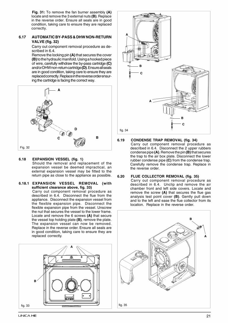
6.17 AUTOMATIC BY-PASS & DHW NON-RETURNVALVE (fig. 32)Carry out component removal procedure as de-scribed in 6.4.Remove the locking pin (A) that secures the cover(B) to the hydraulic manifold. Using a hooked pieceof wire, carefully withdraw the by-pass cartridge (C)and/or DHW non-return cartridge (D). Ensure all sealsare in good condition, taking care to ensure they arereplaced correctly. Replace in the reverse order ensur-ing the cartridge is facing the correct way.
6.18 EXPANSION VESSEL (fig. 1)Should the removal and replacement of theexpansion vessel be deemed impractical, anexternal expansion vessel may be fitted to thereturn pipe as close to the appliance as possible.
6.18.1 EXPANSION VESSEL REMOVAL (withsufficient clearance above, fig. 33)Carry out component removal procedure asdescribed in 6.4. Disconnect the flue from theappliance. Disconnect the expansion vessel fromthe flexible expansion pipe. Disconnect theflexible expansion pipe from the vessel. Unscrewthe nut that secures the vessel to the lower frame.Locate and remove the 6 screws (A) that securethe vessel top holding plate (B), remove the plate.The expansion vessel can now be removed.Replace in the reverse order. Ensure all seals arein good condition, taking care to ensure they arereplaced correctly.
fig. 34
6.19 CONDENSE TRAP REMOVAL (fig. 34)Carry out component removal procedure asdescribed in 6.4. Disconnect the 2 upper rubberscondense pipe (A). Remove the pin (B) that securesthe trap to the air box plate. Disconnect the lowerrubber condense pipe (C) from the condense trap.Carefully remove the condense trap. Replace inthe reverse order.
6.20 FLUE COLLECTOR REMOVAL (fig. 35)Carry out component removal procedure asdescribed in 6.4. Unclip and remove the airchamber front and left side covers. Locate andremove the screw (A) that secures the flue gasanalysis test point cover (B). Gently pull downand to the left and ease the flue collector from itslocation. Replace in the reverse order.
fig. 35
A
C
A
B
A
B
C
B
A
Fig. 31: To remove the fan burner assembly (A)locate and remove the 3 external nuts (B). Replacein the reverse order. Ensure all seals are in goodcondition, taking care to ensure they are replacedcorrectly.
Fig. 32
A
D
C B
fig. 33
B
22
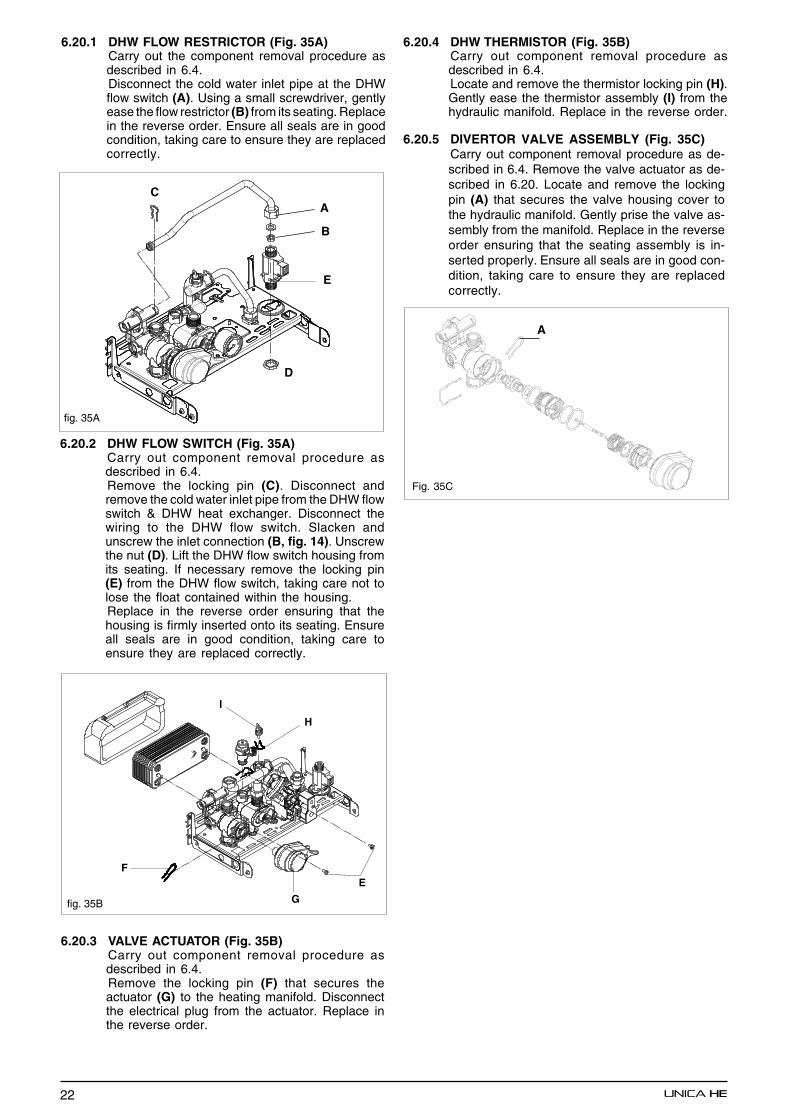
6.20.2 DHW FLOW SWITCH (Fig. 35A)Carry out component removal procedure asdescribed in 6.4.Remove the locking pin (C). Disconnect andremove the cold water inlet pipe from the DHW flowswitch & DHW heat exchanger. Disconnect thewiring to the DHW flow switch. Slacken andunscrew the inlet connection (B, fig. 14). Unscrewthe nut (D). Lift the DHW flow switch housing fromits seating. If necessary remove the locking pin(E) from the DHW flow switch, taking care not tolose the float contained within the housing.Replace in the reverse order ensuring that thehousing is firmly inserted onto its seating. Ensureall seals are in good condition, taking care toensure they are replaced correctly.
6.20.3 VALVE ACTUATOR (Fig. 35B)Carry out component removal procedure asdescribed in 6.4.Remove the locking pin (F) that secures theactuator (G) to the heating manifold. Disconnectthe electrical plug from the actuator. Replace inthe reverse order.
6.20.5 DIVERTOR VALVE ASSEMBLY (Fig. 35C)Carry out component removal procedure as de-scribed in 6.4. Remove the valve actuator as de-scribed in 6.20. Locate and remove the lockingpin (A) that secures the valve housing cover tothe hydraulic manifold. Gently prise the valve as-sembly from the manifold. Replace in the reverseorder ensuring that the seating assembly is in-serted properly. Ensure all seals are in good con-dition, taking care to ensure they are replacedcorrectly.
6.20.1 DHW FLOW RESTRICTOR (Fig. 35A)Carry out the component removal procedure asdescribed in 6.4.Disconnect the cold water inlet pipe at the DHWflow switch (A). Using a small screwdriver, gentlyease the flow restrictor (B) from its seating. Replacein the reverse order. Ensure all seals are in goodcondition, taking care to ensure they are replacedcorrectly.
fig. 35A
A
B
C
D
E
6.20.4 DHW THERMISTOR (Fig. 35B)Carry out component removal procedure asdescribed in 6.4.Locate and remove the thermistor locking pin (H).Gently ease the thermistor assembly (I) from thehydraulic manifold. Replace in the reverse order.
fig. 35B
H
I
E
G
F
Fig. 35C
A

23
SECTION 7 CHECKS, ADJUSTMENTS AND FAULT FINDING
7.1 CHECKING APPLIANCE OPERATIONWhen carrying out any repairs or servicing to theappliance, the relevant commissioning proceduremust be undertaken to ensure the continued safeoperation of the appliance. Particular attentionshould be made to ensure gas soundness, watersoundness, and the electrical integrity of theappliance.
7.2 APPLIANCE MODES OF OPERATION
NOTEThere must be sufficient system water pressure(min. 0.5 bar) to ensure the water pressure switchis activated. If there is insufficient system pressurethe pump and fan will be prevented from operatingand the low-pressure fault code will be displayed.
The 2-digit display can show several differentmodes of operation:
Standby/OFF mode
Frost protection mode active
Combustion analysis mode active
Autostop function active
Normal heating request (example 60oC).
Normal DHW request (example 60oC).
7.2.1 SELECTOR SWITCH IN THE OFF/RESETPOSITIONWhen the selector switch is in the OFF/RESETposition, the following functions are active.
Active functions:• Frost-protection system• Pump & fan anti-block
7.2.1 ON-BOARD FUNCTIONS• THERMOREGULATION: When an external
sensor is connected to the appliance, theelectronic circuitry will automatically adjust theflow outlet temperature to suit local weatherconditions in order to maintain comfort andefficiency. A specific operating curve that ismost suited to the system type and geographicalarea can also be selected.
• OPENTHERM +: OT+ is a communicationprotocol that enables the boiler to be linked orconnected to other OT+ controls. These controls
have been designed to further increase fueleconomy by ensuring the boiler remains in themodulation phase during any heating requests.This reduces the amount of ON/OFF periodsand therefore increases fuel efficiency.
• AUTOSTOP: Further information on theAUTOSTOP function, can be obtained fromyour local Vokera Sales Representative.
• CO FUNCTION: The CO function whenactivated, will allow the appliance to run atmaximum and minimum output whilst acombustion analysis check is being carried out.Whilst the CO function is active, all other functionsare disabled (minimum power operating period,anti-cycle, set-point, etc). Once enabled, theCO function will remain active for a 15-minuteperiod, or until the function is manuallydeactivated
• FROST-PROTECTION: this function is onlyactive when there are no requests for heating orHW. If the temperature drops below 6°C, theboiler will operate on minimum power until thetemperature of the primary thermistor reaches35°C. Thereafter the pump & fan will over-run for30-seconds.
• ANTI-CYCLE FUNCTION: The anti-cyclefunction ensures the burner remains switchedoff for at least 3-minutes after the set-pointhysterisis (set-point + 5-deg).
• PUMP ANTI-BLOCK FUNCTION: when therehas been no heating or HW request for 24-hours,the anti-block cycle is activated. The pump willbe activated for a period of 30-seconds.
• ACTUATOR ANTI-BLOCK FUNCTION: whenthere has been no heating or HW request for 24-hours, the anti-block cycle is activated. Thedivertor valve actuator will motor briefly to theheating position, and then back to the DHWposition.
• DHW PRE-HEAT FUNCTION: When the modeselector switch is in the DHW pre-heat position,the appliance will light periodically to maintainthe temperature of the DHW heat exchanger.When the DHW thermistor and the Primarythermistor fall below 35oC and 55oC respectively,the boiler will fire on minimum +25% power untilthe primary thermistor exceeds 55oC. Thereafterthe pump will over-run for a period of 30-seconds.
7.2.5 HEATING MODEWith the selector switch in the heating & hot waterposition and any additional controls (time clock,programmer, room thermostat, etc,) calling forheat, the appliance will operate in the heatingmode. The pump and fan will be activated via theflow temperature sensor. When the fan is sensedto be operating correctly (tacho signal) , theignition sequence commences. Ignition is sensedby the electronic circuit to ensure flame stabilityat the burner.Once successful ignition has been achieved, theelectronic circuitry increases the gas rate to 75%for a period of 15 minutes.The speed of the fan and therefore the output ofthe boiler is determined by the temperature of thewater sensed by the flow temperature sensor,consequently a high temperature at the flow sensorresults in a lower fan speed. As the water
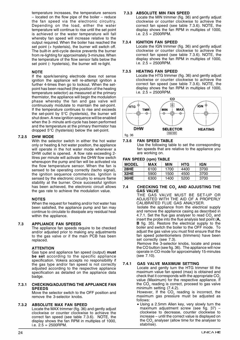
24
temperature increases, the temperature sensors– located on the flow pipe of the boiler – reducethe fan speed via the electronic circuitry.Depending on the load, either the watertemperature will continue to rise until the set pointis achieved or the water temperature will fallwhereby fan speed will increase relative to theoutput required. When the boiler has reached theset point (+ hysterisis), the burner will switch off.The built-in anti-cycle device prevents the burnerfrom re-lighting for approximately 3-minutes. Whenthe temperature of the flow sensor falls below theset point (- hysterisis), the burner will re-light.
NOTEIf the spark/sensing electrode does not senseignition the appliance will re-attempt ignition afurther 4-times then go to lockout. When the set-point has been reached (the position of the heatingtemperature selector) as measured at the primarythermistor, the appliance will begin the modulationphase whereby the fan and gas valve willcontinuously modulate to maintain the set-point.If the temperature continues to rise and exceedsthe set-point by 5°C (hysterisis), the burner willshut down. A new ignition sequence will be enabledwhen the 3- minute anti-cycle has been performedand the temperature at the primary thermistor hasdropped 5°C (hysterisis) below the set-point.
7.2.5 DHW MODEWith the selector switch in either the hot wateronly or heating & hot water position, the appliancewill operate in the hot water mode whenever aDHW outlet is opened. A flow rate exceeding 2-litres per minute will activate the DHW flow switchwhereupon the pump and fan will be activated viathe flow temperature sensor. When the fan issensed to be operating correctly (tacho signal),the ignition sequence commences. Ignition issensed by the electronic circuitry to ensure flamestability at the burner. Once successful ignitionhas been achieved, the electronic circuit allowsthe gas rate to achieve the modulation value.
NOTESWhen the request for heating and/or hot water hasbeen satisfied, the appliance pump and fan maycontinue to circulate to dissipate any residual heatwithin the appliance.
7.3 APPLIANCE FAN SPEEDSThe appliance fan speeds require to be checkedand/or adjusted prior to making any adjustmentsto the gas valve or if the main PCB has beenreplaced.
ATTENTIONGas type and appliance fan speed (output) mustbe set according to the specific appliancespecification. Vokera accepts no responsibility ifthe gas type and/or fan speed is not correctlyadjusted according to the respective appliancespecification as detailed on the appliance databadge.
7.3.1 CHECKING/ADJUSTING THE APPLIANCE FANSPEEDSMove the selector switch to the OFF position andremove the 3-selector knobs.
7.3.2 ABSOLUTE MAX FAN SPEEDLocate the MAX trimmer (fig. 36) and gently adjustclockwise or counter clockwise to achieve thecorrect fan speed (see table 7.3.6). NOTE, thedisplay shows the fan RPM in multiples of 1000,i.e. 2.5 = 2500RPM.
7.3.3 ABSOLUTE MIN FAN SPEEDLocate the MIN trimmer (fig. 36) and gently adjustclockwise or counter clockwise to achieve thecorrect fan speed (see table 7.3.6). NOTE, thedisplay shows the fan RPM in multiples of 1000,i.e. 2.5 = 2500RPM.
7.3.4 IGNITION FAN SPEEDLocate the IGN trimmer (fig. 36) and gently adjustclockwise or counter clockwise to achieve thecorrect fan speed (see table 7.3.6). NOTE, thedisplay shows the fan RPM in multiples of 1000,i.e. 2.5 = 2500RPM.
7.3.5 HEATING FAN SPEEDLocate the HTG trimmer (fig. 36) and gently adjustclockwise or counter clockwise to achieve thecorrect fan speed (see table 7.3.6). NOTE, thedisplay shows the fan RPM in multiples of 1000,i.e. 2.5 = 2500RPM.
fig. 36
7.3.6 FAN SPEED TABLEUse the following table to set the correspondingfan speeds that are relative to the appliance youare working on.
FAN SPEED (rpm) TABLE MODEL MAX MIN HTG IGN 28HE 6100 1700 4400 3700 32HE 5900 1500 4500 3700 36HE 6300 1400 5200 3700
7.4 CHECKING THE CO2 AND ADJUSTING THEGAS VALVETHE GAS VALVE MUST BE SET-UP ORADJUSTED WITH THE AID OF A PROPERLYCALIBRATED FLUE GAS ANALYSER.Isolate the appliance from the electrical supplyand remove the appliance casing as described in4.7.1. Set the flue gas analyser to read CO2 andinsert the probe into the flue analysis test point (A,B fig. 35). Restore the electrical supply to theboiler and switch the boiler to the OFF mode. Toadjust the gas valve you must first ensure that thefan speed potentiometers (trimmers) have beenset correctly (see 7.3).Remove the 3-selector knobs, locate and pressthe CO button (see fig. 36). The appliance will nowoperate in CO mode for approximately 15-minutes(see 7.10).
7.4.1 GAS VALVE MAXIMUM SETTINGLocate and gently turn the HTG trimmer till themaximum value fan speed (max) is obtained andcheck that it corresponds with the appropriate CO2value (Maximum) for the respective appliance. Ifthe CO2 reading is correct, proceed to gas valveminimum setting (7.4.2).However, If the CO2 reading is incorrect, themaximum gas pressure must be adjusted asfollows:• Using a 2.5mm Allen key, very slowly turn the
maximum adjustment screw (see fig. 37) –clockwise to decrease, counter clockwise toincrease – until the correct value is displayed onthe CO2 analyser (allow time for the analyser tostabilise).
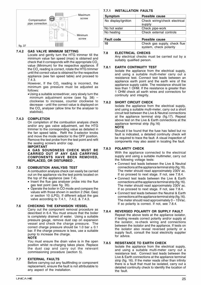
25
fig. 37
7.4.2 GAS VALVE MINIMUM SETTINGLocate and gently turn the HTG trimmer till theminimum value fan speed (max) is obtained andcheck that it corresponds with the appropriate CO
2value (Minimum) for the respective appliance. Ifthe CO
2 reading is correct, rotate the HTG trimmer
until the correct value is obtained for the respectiveappliance (see fan speed table) and proceed to7.4.3.However, If the CO
2 reading is incorrect, the
minimum gas pressure must be adjusted asfollows:• Using a suitable screwdriver, very slowly turn the
minimum adjustment screw (see fig. 38) –clockwise to increase, counter clockwise todecrease - until the correct value is displayed onthe CO2 analyser (allow time for the analyser tostabilise).
7.4.3 COMPLETIONOn completion of the combustion analysis checkand/or any gas valve adjustment, set the HTGtrimmer to the corresponding value as detailed inthe fan speed table. Refit the 3-selector knobsand move the mode selector to the OFF position.Remove the test probe from the test point and refitthe sealing screw/s and/or cap.IMPORTANTA GAS SOUNDNESS CHECK MUST BECARRIED OUT IF ANY GAS CARRYINGCOMPONENTS HAVE BEEN REMOVED,REPLACED, OR DISTURBED .
7.5 COMBUSTION ANALYSIS TESTA combustion analysis check can easily be carriedout on the appliance via the test points located onthe top of the appliance (see 7.4).• Insert the flue gas analyser probe into the flue
gas test point (see fig. 35).• Operate the boiler in CO mode and compare the
values with those shown in section 2 (Nat. Gas)or section 10 (LPG). If different adjust the gasvalve according to 7.4.1, 7.4.2, & 7.4.3.
7.6 CHECKING THE EXPANSION VESSELCarry out the component removal procedure asdescribed in 6.4. You must ensure that the boileris completely drained of water. Using a suitablepressure gauge, remove dust cap on expansionvessel and check the charge pressure. Thecorrect charge pressure should be 1.0 bar ± 0.1bar. If the charge pressure is less, use a suitablepump to increase the charge.NOTEYou must ensure the drain valve is in the openposition whilst re-charging takes place. Replacethe dust cap and carry out the relevantcommissioning procedure (section 5).
7.7 EXTERNAL FAULTSBefore carrying out any faultfinding or componentreplacement, ensure the fault is not attributable toany aspect of the installation.
7.7.1 INSTALLATION FAULTS
Symptom Possible cause No display/ignition Check wiring/check electrical
supply No hot water Check pipe-work No heating Check external controls
Fault code Possible cause 10 Check gas supply, check flue
system, check polarity
7.8 ELECTRICAL CHECKSAny electrical checks must be carried out by asuitably qualified person.
7.8.1 EARTH CONTINUITY TESTIsolate the appliance from the electrical supply,and using a suitable multi-meter carry out aresistance test. Connect test leads between anappliance earth point and the earth wire of theappliance supply cable. The resistance should beless than 1 OHM. If the resistance is greater than1 OHM check all earth wires and connectors forcontinuity and integrity.
7.8.2 SHORT CIRCUIT CHECKIsolate the appliance from the electrical supply,and using a suitable multi-meter, carry out a shortcircuit test between the Live & Neutral connectionsat the appliance terminal strip (fig.17). Repeatabove test on the Live & Earth connections at theappliance terminal strip (fig.16)NOTEShould it be found that the fuse has failed but nofault is indicated, a detailed continuity check willbe required to trace the fault. A visual inspection ofcomponents may also assist in locating the fault.
7.8.3 POLARITY CHECKWith the appliance connected to the electricalsupply and using a suitable multimeter, carry outthe following voltage tests:• Connect test leads between the Live & Neutral
connections at the appliance terminal strip (fig.16).The meter should read approximately 230V ac.If so proceed to next stage. If not, see 7.8.4.
• Connect test leads between the Live & Earthconnections at the appliance terminal strip (fig.16).The meter should read approximately 230V ac.If so proceed to next stage. If not, see 7.8.4.
• Connect test leads between the Neutral & Earthconnections at the appliance terminal strip (fig.16).The meter should read approximately 0 – 15Vac.If so polarity is correct. If not, see 7.8.4.
7.8.4 REVERSED POLARITY OR SUPPLY FAULTRepeat the above tests at the appliance isolator,if testing reveals correct polarity and/or supply atthe isolator, re-check wiring and connectionsbetween the isolator and the appliance. If tests onthe isolator also reveal reversed polarity or asupply fault, consult the local electricity supplierfor advice.
7.8.5 RESISTANCE TO EARTH CHECKIsolate the appliance from the electrical supply,and using a suitable multi-meter carry out aresistance test. Connect test leads between theLive & Earth connections at the appliance terminalstrip (fig. 16). If the meter reads other than infinitythere is a fault that must be isolated, carry out adetailed continuity check to identify the location ofthe fault.
Maximumscrew
Minimumscrew
Compensationpipe connection
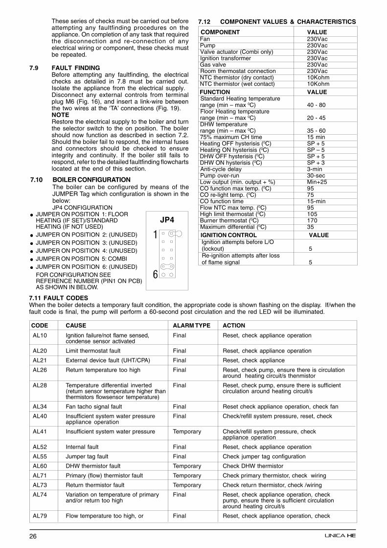
26
These series of checks must be carried out beforeattempting any faultfinding procedures on theappliance. On completion of any task that requiredthe disconnection and re-connection of anyelectrical wiring or component, these checks mustbe repeated.
7.9 FAULT FINDINGBefore attempting any faultfinding, the electricalchecks as detailed in 7.8 must be carried out.Isolate the appliance from the electrical supply.Disconnect any external controls from terminalplug M6 (Fig. 16), and insert a link-wire betweenthe two wires at the ‘TA’ connections (Fig. 19).NOTERestore the electrical supply to the boiler and turnthe selector switch to the on position. The boilershould now function as described in section 7.2.Should the boiler fail to respond, the internal fusesand connectors should be checked to ensureintegrity and continuity. If the boiler still fails torespond, refer to the detailed faultfinding flowchartslocated at the end of this section.
7.11 FAULT CODESWhen the boiler detects a temporary fault condition, the appropriate code is shown flashing on the display. If/when thefault code is final, the pump will perform a 60-second post circulation and the red LED will be illuminated.
CODE CAUSE ALARM TYPE ACTION
AL10 Ignition failure/not flame sensed, Final Reset, check appliance operationcondense sensor activated
AL20 Limit thermostat fault Final Reset, check appliance operation
AL21 External device fault (UHT/CPA) Final Reset, check appliance
AL26 Return temperature too high Final Reset, check pump, ensure there is circulationaround heating circuit/s thenmistor
AL28 Temperature differential inverted Final Reset, check pump, ensure there is sufficient(return sensor temperature higher than circulation around heating circuit/sthermistors flowsensor temperature)
AL34 Fan tacho signal fault Final Reset check appliance operation, check fan
AL40 Insufficient system water pressure Final Check/refill system pressure, reset, checkappliance operation
AL41 Insufficient system water pressure Temporary Check/refill system pressure, checkappliance operation
AL52 Internal fault Final Reset, check appliance operation
AL55 Jumper tag fault Final Check jumper tag configuration
AL60 DHW thermistor fault Temporary Check DHW thermistor
AL71 Primary (flow) thermistor fault Temporary Check primary thermistor, check wiring
AL73 Return thermistor fault Temporary Check return thermistor, check /wiring
AL74 Variation on temperature of primary Final Reset, check appliance operation, checkand/or return too high pump, ensure there is sufficient circulation
around heating circuit/s
AL79 Flow temperature too high, or Final Reset, check appliance operation, check
7.10 BOILER CONFIGURATIONThe boiler can be configured by means of theJUMPER Tag which configuration is shown in thebelow:JP4 CONFIGURATION
●●●●● JUMPER ON POSITION 1: FLOORHEATING (IF SET)/STANDARDHEATING (IF NOT USED)
●●●●● JUMPER ON POSITION 2: (UNUSED)●●●●● JUMPER ON POSITION 3: (UNUSED)●●●●● JUMPER ON POSITION 4: (UNUSED)●●●●● JUMPER ON POSITION 5: COMBI●●●●● JUMPER ON POSITION 6: (UNUSED)
FOR CONFIGURATION SEEREFERENCE NUMBER (PIN1 ON PCB)AS SHOWN IN BELOW.
7.12 COMPONENT VALUES & CHARACTERISTICS
COMPONENT VALUE Fan 230Vac Pump 230Vac Valve actuator (Combi only) 230Vac Ignition transformer 230Vac Gas valve 230Vac Room thermostat connection 230Vac NTC thermistor (dry contact) 10Kohm NTC thermistor (wet contact) 10Kohm FUNCTION VALUE Standard Heating temperature range (min – max 0C) 40 - 80 Floor Heating temperature range (min – max 0C) 20 - 45 DHW temperature range (min – max 0C) 35 - 60 75% maximum CH time 15 min Heating OFF hysterisis (0C) SP + 5 Heating ON hysterisis (0C) SP – 5 DHW OFF hysterisis (0C) SP + 5 DHW ON hysterisis (0C) SP + 3 Anti-cycle delay 3-min Pump over-run 30-sec Low output (min. output + %) Min+25 CO function max temp. (0C) 95 CO re-light temp. (0C) 75 CO function time 15-min Flow NTC max temp. (0C) 95 High limit thermostat (0C) 105 Burner thermostat (0C) 170 Maximum differential (0C) 35 IGNITION CONTROL VALUE Ignition attempts before L/O (lockout) 5 Re-ignition attempts after loss of flame signal 5
JP4

27
8.1 EXTERNAL WIRINGThe appliance comes with a factory fitted (TA)link to allow basic operation of the boiler via themode selector switch. If external controls are tobe added to the system, they must be connectedto the appliance as shown in the followingdiagrams. For advice on controls that are notfeatured in this book, please contact Vokeratechnical on 0870 333 0520.
8.1.1 EXTERNAL WIRING LIMITATIONSAny external wiring must remain within the limitsas detailed in the table below
CONNECTION MAX. LENGTH External sensor 30-metres Room thermostat 30-metres OT+ connection 30-metres
8.2 TYPICAL CONTROL APPLICATIONSThe appliance can be used with the followingcontrols:• Single-channel, voltage-free time clocks (fig.
39).• Programmable room thermostats (fig. 40).• OT+ control, please contact Vokera technical
for detailed instruction on specific OT+ controls.• Vokera external sensor.
8.3 OTHER DEVICESContact the controls manufacturer and/or Vokeratechnical department should you require morespecific information on the suitability of a particularcontrol. Further guidance on the recommendedpractice for the installation of external controls,can be found in CHeSS – HC5/HC6(www.energyefficiency.gov.uk).
SECTION 8 WIRING DIAGRAMS
8.4 VOKERA MECHANICAL CLOCK (code )The Vokera mechanical clock (product code) isentirely suitable for the Unica HE range andeliminates the need for an external time control.The kit is comprised of the following:• Mechanical clock• Wiring harness• instructions
Fig. 39 Fig. 41
U.H.T. = underfloor heating thermostatC.P.A.= condensate pump alarmE.S.= external sensorOT+= opentherm + connection
OPTIONAL DEVICE (24V) TERMINAL BLOCK
Fig. 40
Isolate the appliance from the electrical supplyand remove the clock blanking disc from the clockaperture on the boiler. Keep the screws safe, asthey will be required to secure the programmer tothe aperture.
Connect the spade connections of the wiringharness to the clock as shown in figure 39.Connect the other end of the wiring harness asdetailed in figure 41.Secure the clock to the clock aperture using thescrews previously removed from the blanking disc.
IMPORTANT• The boiler must always be supplied with a
permanent 230V electrical supply.
• Always remove the link between TA & TA on theappliance high-voltage terminal strip wheneveradditional controls are connected to theappliance.
• Do not connect any controls or auxiliaryequipment to the low-voltage terminal strip, otherthan that approved/supplied by Vokera Ltd.
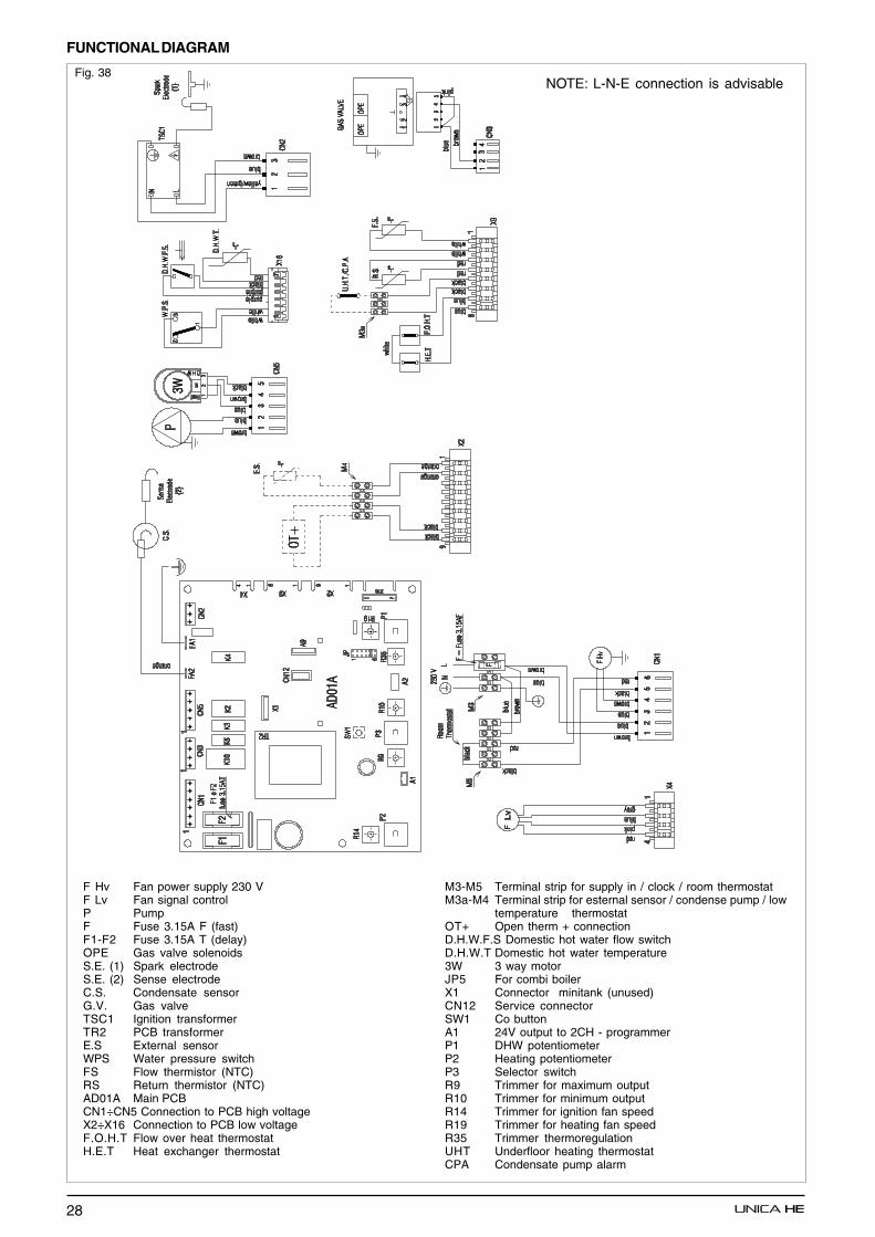
28
FUNCTIONAL DIAGRAM
Fig. 38NOTE: L-N-E connection is advisable
F Hv Fan power supply 230 VF Lv Fan signal controlP PumpF Fuse 3.15A F (fast)F1-F2 Fuse 3.15A T (delay)OPE Gas valve solenoidsS.E. (1) Spark electrodeS.E. (2) Sense electrodeC.S. Condensate sensorG.V. Gas valveTSC1 Ignition transformerTR2 PCB transformerE.S External sensorWPS Water pressure switchFS Flow thermistor (NTC)RS Return thermistor (NTC)AD01A Main PCBCN1÷CN5 Connection to PCB high voltageX2÷X16 Connection to PCB low voltageF.O.H.T Flow over heat thermostatH.E.T Heat exchanger thermostat
M3-M5 Terminal strip for supply in / clock / room thermostatM3a-M4 Terminal strip for esternal sensor / condense pump / low
temperature thermostatOT+ Open therm + connectionD.H.W.F.S Domestic hot water flow switchD.H.W.T Domestic hot water temperature3W 3 way motorJP5 For combi boilerX1 Connector minitank (unused)CN12 Service connectorSW1 Co buttonA1 24V output to 2CH - programmerP1 DHW potentiometerP2 Heating potentiometerP3 Selector switchR9 Trimmer for maximum outputR10 Trimmer for minimum outputR14 Trimmer for ignition fan speedR19 Trimmer for heating fan speedR35 Trimmer thermoregulationUHT Underfloor heating thermostatCPA Condensate pump alarm
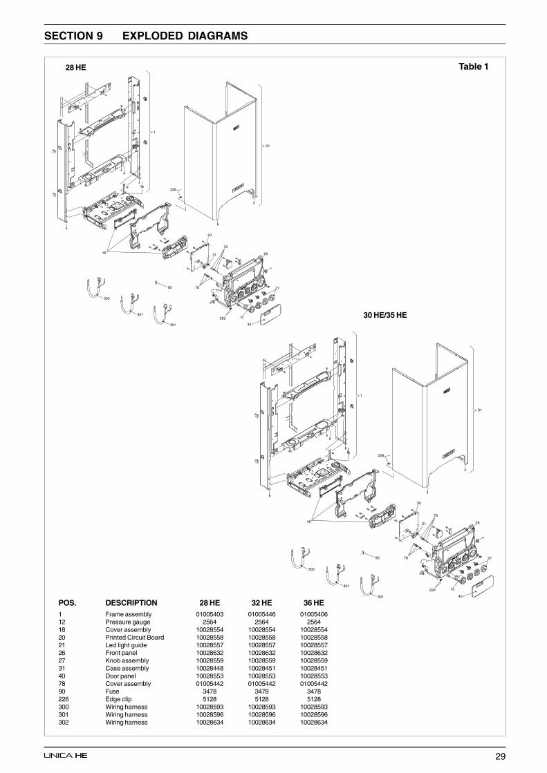
29
40
26
12226
20
2118
226
90
301
301
300
31
1
78
78
27
SECTION 9 EXPLODED DIAGRAMS
Table 128 HE
30 HE/35 HE
40
26
12226
20
2118
226
90
301
301
300
31
1
78
78
27
POS. DESCRIPTION 28 HE 32 HE 36 HE1 Frame assembly 01005403 01005446 0100540612 Pressure gauge 2564 2564 256418 Cover assembly 10028554 10028554 1002855420 Printed Circuit Board 10028558 10028558 1002855821 Led light guide 10028557 10028557 1002855726 Front panel 10028632 10028632 1002863227 Knob assembly 10028559 10028559 1002855931 Case assembly 10028448 10028451 1002845140 Door panel 10028553 10028553 1002855378 Cover assembly 01005442 01005442 0100544290 Fuse 3478 3478 3478226 Edge clip 5128 5128 5128300 Wiring harness 10028593 10028593 10028593301 Wiring harness 10028596 10028596 10028596302 Wiring harness 10028634 10028634 10028634
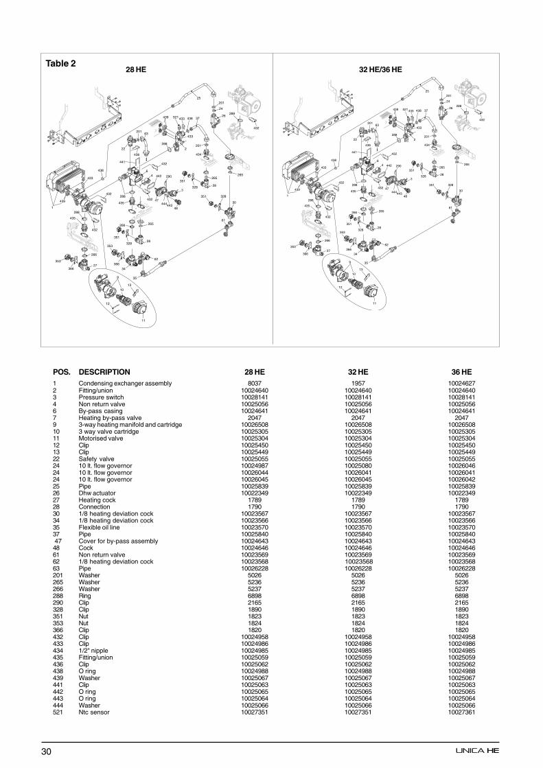
30
288
432
438
265265
265
201
3
353
366
35
34
62
28351
328
28351
328
27353
366
351 328
61
30
435
288
432
439
1
432
432
47444443
48
290442
6
7
4
435
288432
441
436
22
63
266
266
26
25
24
201
433
288
2
521
433
201
434
37438439
433
9
10
11
12
13
288
432
438
265265
265
201
3
353
366
35
34
62
28351
328
28351
328
27353
366
351 328
61
30
435
288
432
439
1
432
432
47444443
48
290442
6
7
4
435
288432
441
436
22
63
266
266
26
25
24
201
433
288
2
521
433
201
434
37438439
433
9
10
11
12
13
POS. DESCRIPTION 28 HE 32 HE 36 HE1 Condensing exchanger assembly 8037 1957 100246272 Fitting/union 10024640 10024640 100246403 Pressure switch 10028141 10028141 100281414 Non return valve 10025056 10025056 100250566 By-pass casing 10024641 10024641 100246417 Heating by-pass valve 2047 2047 20479 3-way heating manifold and cartridge 10026508 10026508 1002650810 3 way valve cartridge 10025305 10025305 1002530511 Motorised valve 10025304 10025304 1002530412 Clip 10025450 10025450 1002545013 Clip 10025449 10025449 1002544922 Safety valve 10025055 10025055 1002505524 10 lt. flow governor 10024987 10025080 1002604624 10 lt. flow governor 10026044 10026041 1002604124 10 lt. flow governor 10026045 10026045 1002604225 Pipe 10025839 10025839 1002583926 Dhw actuator 10022349 10022349 1002234927 Heating cock 1789 1789 178928 Connection 1790 1790 179030 1/8 heating deviation cock 10023567 10023567 1002356734 1/8 heating deviation cock 10023566 10023566 1002356635 Flexible oil line 10023570 10023570 1002357037 Pipe 10025840 10025840 10025840 47 Cover for by-pass assembly 10024643 10024643 1002464348 Cock 10024646 10024646 1002464661 Non return valve 10023569 10023569 1002356962 1/8 heating deviation cock 10023568 10023568 1002356863 Pipe 10026228 10026228 10026228201 Washer 5026 5026 5026265 Washer 5236 5236 5236266 Washer 5237 5237 5237288 Ring 6898 6898 6898290 Clip 2165 2165 2165328 Clip 1890 1890 1890351 Nut 1823 1823 1823353 Nut 1824 1824 1824366 Clip 1820 1820 1820432 Clip 10024958 10024958 10024958433 Clip 10024986 10024986 10024986434 1/2" nipple 10024985 10024985 10024985435 Fitting/union 10025059 10025059 10025059436 Clip 10025062 10025062 10025062438 O ring 10024988 10024988 10024988439 Washer 10025067 10025067 10025067441 Clip 10025063 10025063 10025063442 O ring 10025065 10025065 10025065443 O ring 10025064 10025064 10025064444 Washer 10025066 10025066 10025066521 Ntc sensor 10027351 10027351 10027361
Table 228 HE 32 HE/36 HE
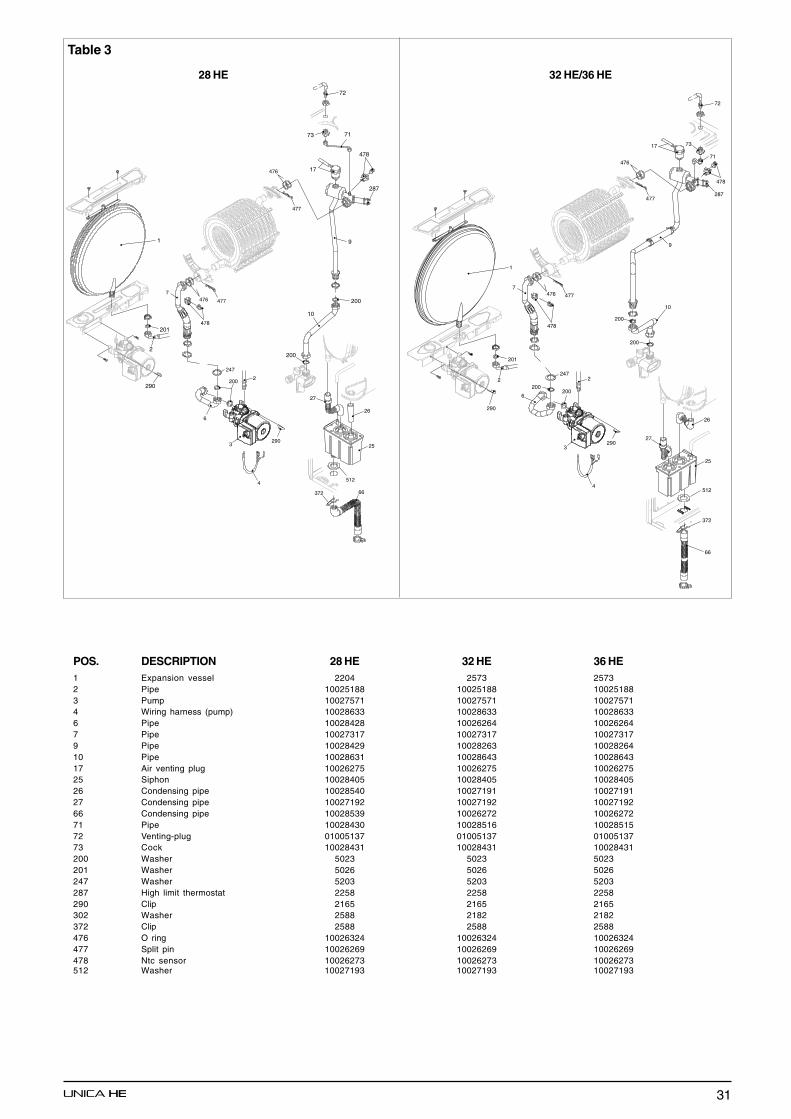
31
Table 3
290
2
201
3290
2200
6
66
25
27
372
512
26
7
478
4
247
476 477
477
476
1
287
7173
72
478
9
200
10
200
17
3290
2
200
7
6
478
2472
201
290
200
10
9
287
71
73
72
478
17
66
4
476 477
477
476
200
25
26
27
372
512
200
1
28 HE 32 HE/36 HE
POS. DESCRIPTION 28 HE 32 HE 36 HE1 Expansion vessel 2204 2573 25732 Pipe 10025188 10025188 100251883 Pump 10027571 10027571 100275714 Wiring harness (pump) 10028633 10028633 100286336 Pipe 10028428 10026264 100262647 Pipe 10027317 10027317 100273179 Pipe 10028429 10028263 1002826410 Pipe 10028631 10028643 1002864317 Air venting plug 10026275 10026275 1002627525 Siphon 10028405 10028405 1002840526 Condensing pipe 10028540 10027191 1002719127 Condensing pipe 10027192 10027192 1002719266 Condensing pipe 10028539 10026272 1002627271 Pipe 10028430 10028516 1002851572 Venting-plug 01005137 01005137 0100513773 Cock 10028431 10028431 10028431200 Washer 5023 5023 5023201 Washer 5026 5026 5026247 Washer 5203 5203 5203287 High limit thermostat 2258 2258 2258290 Clip 2165 2165 2165302 Washer 2588 2182 2182372 Clip 2588 2588 2588476 O ring 10026324 10026324 10026324477 Split pin 10026269 10026269 10026269478 Ntc sensor 10026273 10026273 10026273512 Washer 10027193 10027193 10027193
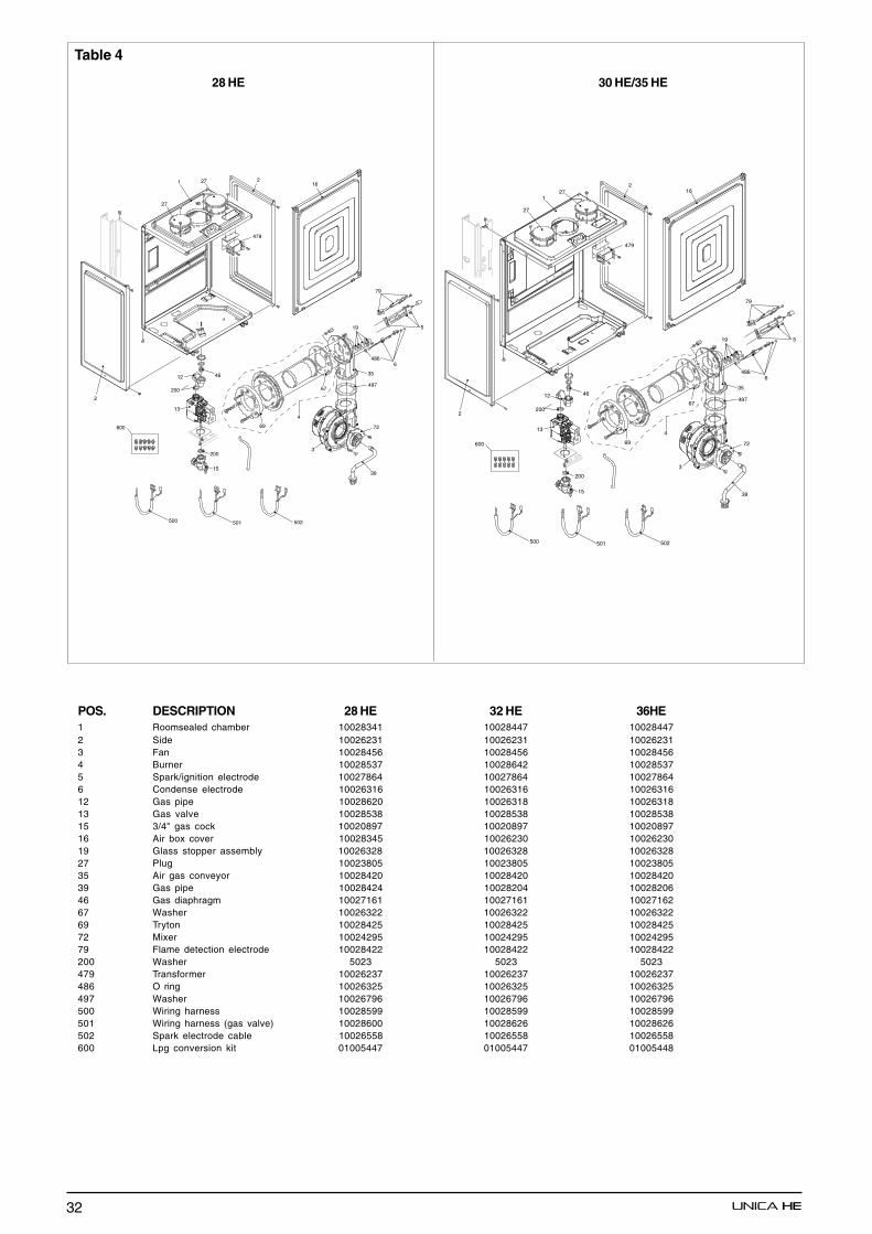
32
46
13
200
12
200
15
21
27
2
479
16
69
4
519
6
35
67
3
72
486
497
39
79
27
500 501 502
600
46
39
2
1
2
479
16
13
200
12
200
15
27
27
69
4
519
6
35
67
3
72
486
497
79
500 501 502
600
Table 4
28 HE 30 HE/35 HE
POS. DESCRIPTION 28 HE 32 HE 36HE1 Roomsealed chamber 10028341 10028447 100284472 Side 10026231 10026231 100262313 Fan 10028456 10028456 100284564 Burner 10028537 10028642 100285375 Spark/ignition electrode 10027864 10027864 100278646 Condense electrode 10026316 10026316 1002631612 Gas pipe 10028620 10026318 1002631813 Gas valve 10028538 10028538 1002853815 3/4" gas cock 10020897 10020897 1002089716 Air box cover 10028345 10026230 1002623019 Glass stopper assembly 10026328 10026328 1002632827 Plug 10023805 10023805 1002380535 Air gas conveyor 10028420 10028420 1002842039 Gas pipe 10028424 10028204 1002820646 Gas diaphragm 10027161 10027161 1002716267 Washer 10026322 10026322 1002632269 Tryton 10028425 10028425 1002842572 Mixer 10024295 10024295 1002429579 Flame detection electrode 10028422 10028422 10028422200 Washer 5023 5023 5023479 Transformer 10026237 10026237 10026237486 O ring 10026325 10026325 10026325497 Washer 10026796 10026796 10026796500 Wiring harness 10028599 10028599 10028599501 Wiring harness (gas valve) 10028600 10028626 10028626502 Spark electrode cable 10026558 10026558 10026558600 Lpg conversion kit 01005447 01005447 01005448
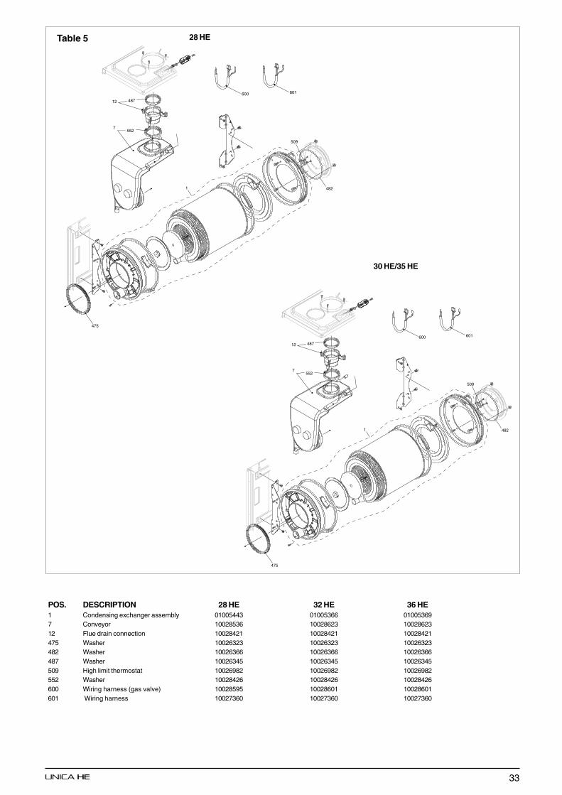
33
Table 5
7
12 487
552
482
475
1
509
600 601
7
12 487
552
482
475
1
509
600 601
28 HE
30 HE/35 HE
POS. DESCRIPTION 28 HE 32 HE 36 HE1 Condensing exchanger assembly 01005443 01005366 010053697 Conveyor 10028536 10028623 1002862312 Flue drain connection 10028421 10028421 10028421475 Washer 10026323 10026323 10026323482 Washer 10026366 10026366 10026366487 Washer 10026345 10026345 10026345509 High limit thermostat 10026982 10026982 10026982552 Washer 10028426 10028426 10028426600 Wiring harness (gas valve) 10028595 10028601 10028601601 Wiring harness 10027360 10027360 10027360
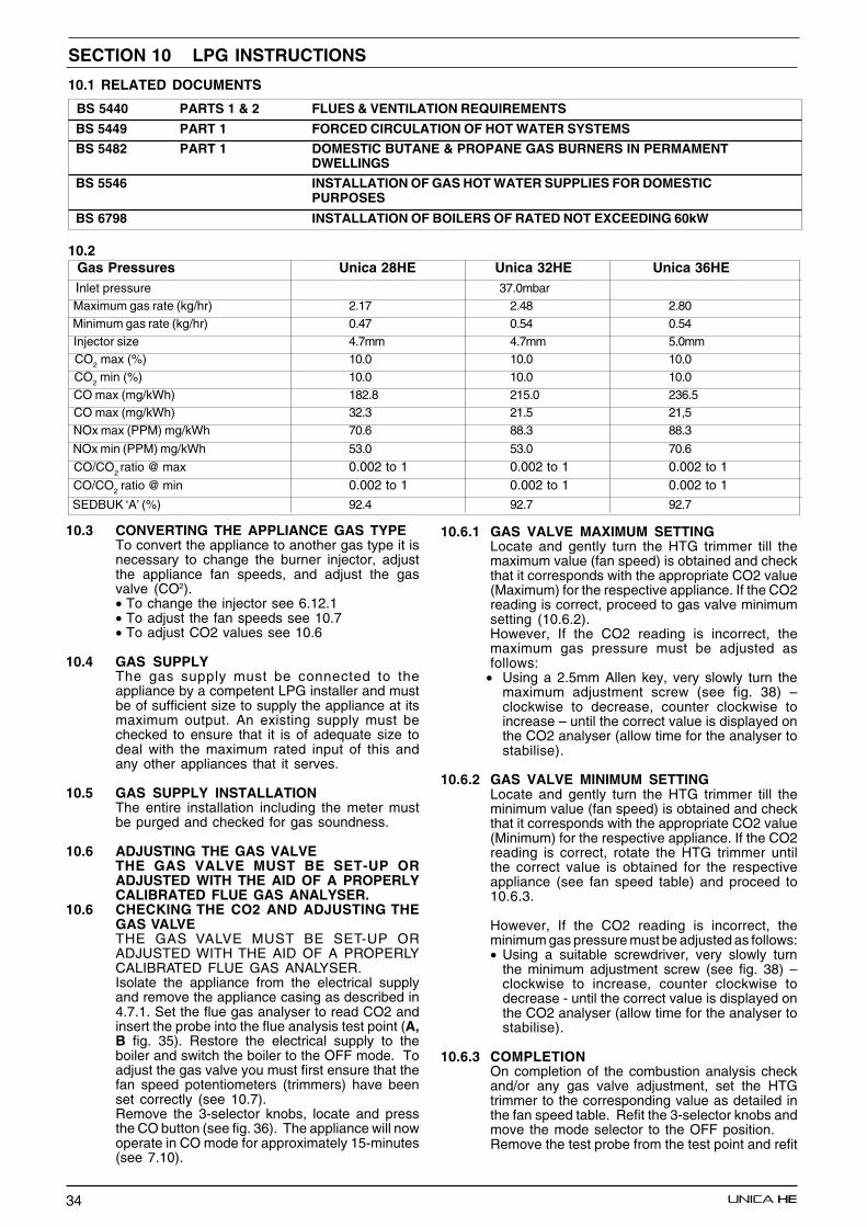
34
SECTION 10 LPG INSTRUCTIONS
10.1 RELATED DOCUMENTS
BS 5440 PARTS 1 & 2 FLUES & VENTILATION REQUIREMENTS
BS 5449 PART 1 FORCED CIRCULATION OF HOT WATER SYSTEMS
BS 5482 PART 1 DOMESTIC BUTANE & PROPANE GAS BURNERS IN PERMAMENTDWELLINGS
BS 5546 INSTALLATION OF GAS HOT WATER SUPPLIES FOR DOMESTICPURPOSES
BS 6798 INSTALLATION OF BOILERS OF RATED NOT EXCEEDING 60kW
10.2 Gas Pressures Unica 28HE Unica 32HE Unica 36HE Inlet pressure 37.0mbar Maximum gas rate (kg/hr) 2.17 2.48 2.80 Minimum gas rate (kg/hr) 0.47 0.54 0.54 Injector size 4.7mm 4.7mm 5.0mm CO2 max (%) 10.0 10.0 10.0 CO2 min (%) 10.0 10.0 10.0 CO max (mg/kWh) 182.8 215.0 236.5 CO max (mg/kWh) 32.3 21.5 21,5 NOx max (PPM) mg/kWh 70.6 88.3 88.3
NOx min (PPM) mg/kWh 53.0 53.0 70.6
CO/CO2 ratio @ max 0.002 to 1 0.002 to 1 0.002 to 1 CO/CO2 ratio @ min 0.002 to 1 0.002 to 1 0.002 to 1
SEDBUK ‘A’ (%) 92.4 92.7 92.7
10.3 CONVERTING THE APPLIANCE GAS TYPETo convert the appliance to another gas type it isnecessary to change the burner injector, adjustthe appliance fan speeds, and adjust the gasvalve (CO2).• To change the injector see 6.12.1• To adjust the fan speeds see 10.7• To adjust CO2 values see 10.6
10.4 GAS SUPPLYThe gas supply must be connected to theappliance by a competent LPG installer and mustbe of sufficient size to supply the appliance at itsmaximum output. An existing supply must bechecked to ensure that it is of adequate size todeal with the maximum rated input of this andany other appliances that it serves.
10.5 GAS SUPPLY INSTALLATIONThe entire installation including the meter mustbe purged and checked for gas soundness.
10.6 ADJUSTING THE GAS VALVETHE GAS VALVE MUST BE SET-UP ORADJUSTED WITH THE AID OF A PROPERLYCALIBRATED FLUE GAS ANALYSER.
10.6 CHECKING THE CO2 AND ADJUSTING THEGAS VALVETHE GAS VALVE MUST BE SET-UP ORADJUSTED WITH THE AID OF A PROPERLYCALIBRATED FLUE GAS ANALYSER.Isolate the appliance from the electrical supplyand remove the appliance casing as described in4.7.1. Set the flue gas analyser to read CO2 andinsert the probe into the flue analysis test point (A,B fig. 35). Restore the electrical supply to theboiler and switch the boiler to the OFF mode. Toadjust the gas valve you must first ensure that thefan speed potentiometers (trimmers) have beenset correctly (see 10.7).Remove the 3-selector knobs, locate and pressthe CO button (see fig. 36). The appliance will nowoperate in CO mode for approximately 15-minutes(see 7.10).
10.6.1 GAS VALVE MAXIMUM SETTINGLocate and gently turn the HTG trimmer till themaximum value (fan speed) is obtained and checkthat it corresponds with the appropriate CO2 value(Maximum) for the respective appliance. If the CO2reading is correct, proceed to gas valve minimumsetting (10.6.2).However, If the CO2 reading is incorrect, themaximum gas pressure must be adjusted asfollows:
• Using a 2.5mm Allen key, very slowly turn themaximum adjustment screw (see fig. 38) –clockwise to decrease, counter clockwise toincrease – until the correct value is displayed onthe CO2 analyser (allow time for the analyser tostabilise).
10.6.2 GAS VALVE MINIMUM SETTINGLocate and gently turn the HTG trimmer till theminimum value (fan speed) is obtained and checkthat it corresponds with the appropriate CO2 value(Minimum) for the respective appliance. If the CO2reading is correct, rotate the HTG trimmer untilthe correct value is obtained for the respectiveappliance (see fan speed table) and proceed to10.6.3.
However, If the CO2 reading is incorrect, theminimum gas pressure must be adjusted as follows:• Using a suitable screwdriver, very slowly turn
the minimum adjustment screw (see fig. 38) –clockwise to increase, counter clockwise todecrease - until the correct value is displayed onthe CO2 analyser (allow time for the analyser tostabilise).
10.6.3 COMPLETIONOn completion of the combustion analysis checkand/or any gas valve adjustment, set the HTGtrimmer to the corresponding value as detailed inthe fan speed table. Refit the 3-selector knobs andmove the mode selector to the OFF position.Remove the test probe from the test point and refit

35
IMPORTANTA GAS SOUNDNESS CHECK MUST BECARRIED OUT IF ANY GAS CARRYINGCOMPONENTS HAVE BEEN REMOVED,REPLACED, OR DISTURBED .
FAN SPEED (rpm) TABLE - LPG
MODEL MAX MIN HTG IGN 28HE 6100 1700 4300 3700
32HE 5900 1500 4500 3700
36HE 6300 1400 5200 3700
10.7 APPLIANCE FAN SPEEDSThe appliance fan speeds require to be checkedand/or adjusted prior to making any adjustmentsto the gas valve or if the main PCB has beenreplaced.
ATTENTIONGas type and appliance fan speed (output) mustbe set according to the specific appliancespecification. Vokera accepts no responsibility ifthe gas type and/or fan speed is not correctlyadjusted according to the respective appliancespecification as detailed on the appliance databadge.
10.7.1 CHECKING/ADJUSTING THE APPLIANCE FANSPEEDSMove the selector switch to the OFF position andremove the 3-selector knobs.
10.7.2 ABSOLUTE MAX FAN SPEEDLocate the MAX trimmer (fig. 36) and gently adjustclockwise or counter clockwise to achieve thecorrect fan speed (see table above). NOTE, thedisplay shows the fan RPM in multiples of 1000,i.e. 2.5 = 2500RPM.
10.7.3 ABSOLUTE MIN FAN SPEEDLocate the MIN trimmer (fig. 36) and gently adjustclockwise or counter clockwise to achieve thecorrect fan speed (see table above). NOTE, thedisplay shows the fan RPM in multiples of 1000,i.e. 2.5 = 2500RPM.
10.7.4 IGNITION FAN SPEEDLocate the IGN trimmer (fig. 36) and gently adjustclockwise or counter clockwise to achieve thecorrect fan speed (see table above). NOTE, thedisplay shows the fan RPM in multiples of 1000,i.e. 2.5 = 2500RPM.
10.7.5 HEATING FAN SPEEDLocate the HTG trimmer (fig. 36) and gently adjustclockwise or counter clockwise to achieve thecorrect fan speed (see table above). NOTE, thedisplay shows the fan RPM in multiples of 1000,i.e. 2.5 = 2500RPM.
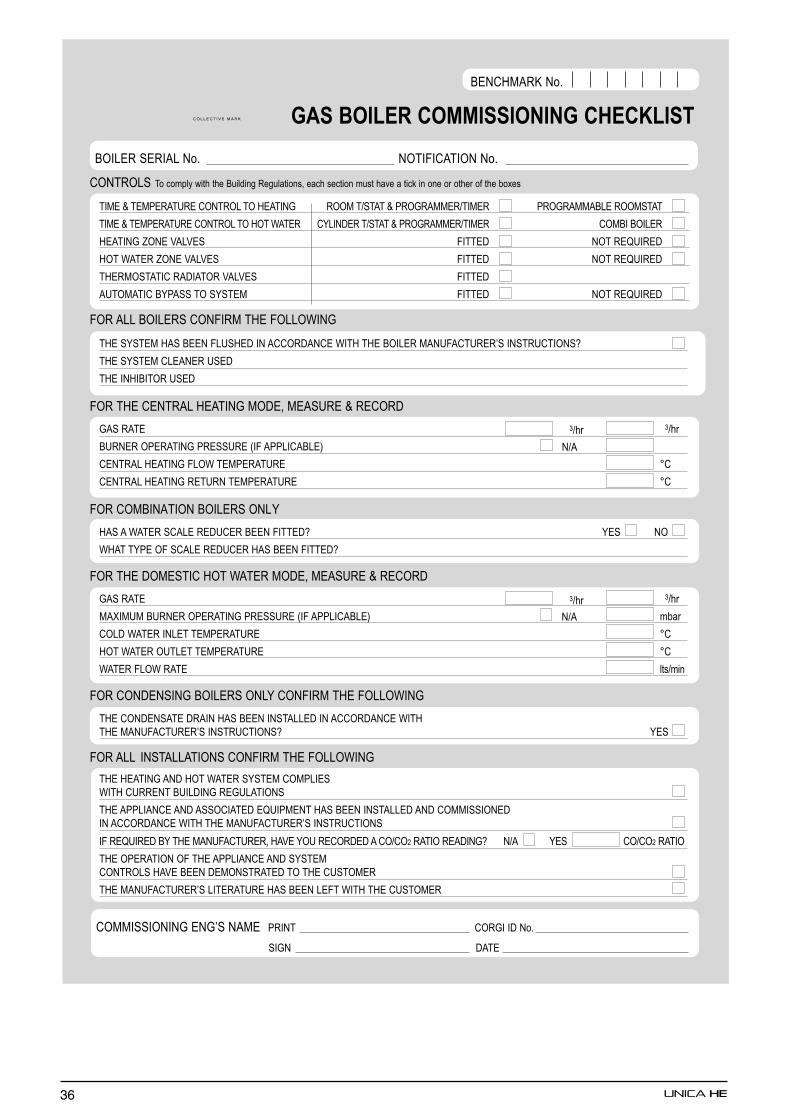
36
�������� ����� ����������� �������� ��������������������������������������������� �!��
�"#$%�$#&$�'�(�$������� ��)$'�"�* ���#�+��'� %&��*�'##$�+�"#$� &��*�'##'��$���#��'�
�"#$% �$#&$�'�(�$������� ��)�� ,'�$� �-�"�.$��+��'� %&��*�'##$�+�"#$� ��#�"��"�$�
)$'�"�*/��$0'�0$� 1"��$. ��� �$2("�$.
)�� ,'�$�/��$0'�0$� 1"��$. ��� �$2("�$.
�)$�#���'�"��'."'���0'�0$� 1"��$.
'(��#'�"��-&'�����-��$# 1"��$. ��� �$2("�$.
1��'�� ��"�$�����1"�#�)$1����,"�*
�)$�-��$#)'��$$�1�(�)$."�'����.'��$,"�)�)$��"�$�#'�(1'��(�$�3�"����(��"���4
�)$�-��$#��$'�$�(�$.
�)$"�)"�"���(�$.
1���)$�$���'� )$'�"�*#�.$�#$'�(�$%�$���.
*'��'�$ 5+��
�(��$��&$�'�"�*&�$��(�$6"1 '&&�"�'��$7
�$���'� )$'�"�*1��, �$#&$�'�(�$ 8�
�$���'� )$'�"�*�$�(���$#&$�'�(�$ 8�
1����#�"�'�"����"�$�����-
)'�' ,'�$���'�$�$.(�$��$$�1"��$.4-$���
,)'� �-&$�1��'�$�$.(�$�)'��$$�1"��$.4
1���)$.�#$��"�)��,'�$�#�.$�#$'�(�$%�$���.
*'��'�$ 5+��
#'9"#(#�(��$��&$�'�"�*&�$��(�$6"1'&&�"�'��$7 � ��
���.,'�$�"��$� �$#&$�'�(�$ 8�
)�� ,'�$��(��$� �$#&$�'�(�$ 8�
,'�$�1��,�'�$ ��+���
1�����.$��"�*��"�$�����- ���1"�#�)$1����,"�*
�)$���.$��'�$.�'"�)'��$$�"���'��$."�'����.'��$,"�)�)$#'�(1'��(�$�3�"����(��"���4 -$�
1�� '�� "���'��'�"������1"�#�)$1����,"�*
�)$)$'�"�*'�.)�� ,'�$��-��$#��#&�"$�,"�)�(��$�� �("�."�*�$*(�'�"���
�)$ '&&�"'��$ '�. '����"'�$.$2("&#$�� )'��$$�"���'��$.'�.��##"��"��$."�'����.'��$,"�)�)$#'�(1'��(�$�3�"����(��"���
"1�$2("�$.�- �)$#'�(1'��(�$��)'0$-�(�$���.$.'��+��: �'�"��$'."�*4 �+' -$� ��+��: �'�"�
�)$�&$�'�"���1�)$'&&�"'��$'�.�-��$#��������)'0$�$$�.$#�����'�$.���)$�(���#$�
�)$#'�(1'��(�$�3��"�$�'�(�$)'��$$��$1� ,"�)�)$�(���#$�
5+��
5+��
��##"��"��"�*$�*3��'#$ &�"�� ���*"".��;
�"*� .'�$
��"�$��$�"'� ��; ���"1"�'�"�� ��;
�$��)#'�<��;
������������������ � ����������� � � � � � � � � � � �
�+'
�+'
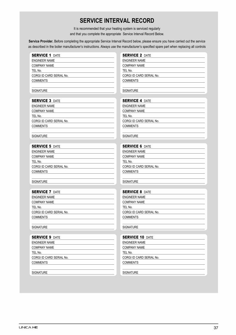
37
������ ��������"����������������������������������������������� �� �
������������� �����������������������"������ ������� ��;
����������������� ��������� �������������������������"������ ����� � ���� ������������������������������������������ ������� �� �������������3������������;' ���������������������3������������������������� ����� ����� �
��������� .'�$
$�*"�$$��'#$
��#&'�- �'#$
�$� ��;
���*"".�'�.�$�"'� ��;
��##$���
�"*�'�(�$
�������� .'�$
$�*"�$$��'#$
��#&'�- �'#$
�$� ��;
���*"".�'�.�$�"'� ��;
��##$���
�"*�'�(�$
�������� .'�$
$�*"�$$��'#$
��#&'�- �'#$
�$� ��;
���*"".�'�.�$�"'� ��;
��##$���
�"*�'�(�$
��������� .'�$
$�*"�$$��'#$
��#&'�- �'#$
�$� ��;
���*"".�'�.�$�"'� ��;
��##$���
�"*�'�(�$
��������� .'�$
$�*"�$$��'#$
��#&'�- �'#$
�$� ��;
���*"".�'�.�$�"'� ��;
��##$���
�"*�'�(�$
�������� .'�$
$�*"�$$��'#$
��#&'�- �'#$
�$� ��;
���*"".�'�.�$�"'� ��;
��##$���
�"*�'�(�$
��������� .'�$
$�*"�$$��'#$
��#&'�- �'#$
�$� ��;
���*"".�'�.�$�"'� ��;
��##$���
�"*�'�(�$
��������� .'�$
$�*"�$$��'#$
��#&'�- �'#$
�$� ��;
���*"".�'�.�$�"'� ��;
��##$���
�"*�'�(�$
��������� .'�$
$�*"�$$��'#$
��#&'�- �'#$
�$� ��;
���*"".�'�.�$�"'� ��;
��##$���
�"*�'�(�$
���������� .'�$
$�*"�$$��'#$
��#&'�- �'#$
�$� ��;
���*"".�'�.�$�"'� ��;
��##$���
�"*�'�(�$
Cod
. 100
2863
5 - 0
6/06
- Ed
. 1
Registered address:Vokèra Ltd
Borderlake HouseUnit 7 Riverside Industrial Estate
London ColneyHerts AL2 1HG
www.vokera.co.ukwww.vokera.ie
Sales, General EnquiresT 0844 391 099
F 0844 391 0998
Vokèra IrelandWest Court, Callan
Co KilkennyT 056 7755057F 056 7755060
Vokèra Limited reserve the right to changespecification without prior notice
Consumers statutory rights are not affected.
A Riello Group Company.Company Reg No: 1047779