Uni-Drum Supply System - DASS · Uni-Drum™ Supply System Bulk Supply System for 300 Gallon (1200...
84
Uni-Drum Right Hand Supply Unit Instructions–Parts List Uni-Drum™ Supply System Bulk Supply System for 300 Gallon (1200 Liter) Magnadrums. The Uni-Drum supply system evacuates 300 gallon (1200 liter) magnadrums or other tote drums of the same size and capacity. The Uni-Drum pumps and transfers flowable and highly viscous materials such as sealant, adhesives, and sound deadeners from bulk drums with maximum efficiency. The Uni-Drum is built to work with other high pressure equipment to optimize material use. For professional use only. Not for use in explosive atmospheres. Important Safety Instructions Read all warnings and instructions in this manual. Save these instructions. Uni-Drum Left Hand Supply Unit Ti4624a See page 2 for List of Models, Maximum Outlet Pressure, and Maximum Fluid Flow. See page 3 for Table of Contents. 309028ZAC EN
Transcript of Uni-Drum Supply System - DASS · Uni-Drum™ Supply System Bulk Supply System for 300 Gallon (1200...

Uni-Drum Right Hand Supply Unit
Instructions–Parts List
Uni-Drum™ Supply SystemBulk Supply System for 300 Gallon (1200 Liter) Magnadrums.
The Uni-Drum supply system evacuates 300 gallon (1200 liter) magnadrums or other tote drums ofthe same size and capacity. The Uni-Drum pumps and transfers flowable and highly viscous materialssuch as sealant, adhesives, and sound deadeners from bulk drums with maximum efficiency.
The Uni-Drum is built to work with other high pressure equipment to optimize material use.
For professional use only.
Not for use in explosive atmospheres.
Important Safety InstructionsRead all warnings and instructions in this manual.Save these instructions.
Uni-Drum Left Hand Supply UnitTi4624a
See page 2 for List of Models, Maximum Outlet Pressure,and Maximum Fluid Flow. See page 3 for Table of Contents.
309028ZAC��

2 309028
List of ModelsThe Uni-Drum supply units listed below are covered in this manual. For specific pump information, refer to the chartin Servicing the Pumps on page 51.
Supply Unit PartNo.
Pump Ratio Max. Outlet Pressure Max. Fluid Flow@ 60 cpm
Pump Manual
246981 (Left Hand)
Premier, SST, silicone ni-tride, ceramic
45:1 4500 psi (31.0 MPa, 310 bar)
6.9 gpm (26 lpm) 308148
246982(Right Hand)
Premier, SST, silicone ni-tride, ceramic
45:1 4500 psi (31.0 MPa, 310 bar)
6.9 gpm (26 lpm) 308148
248306(Left Hand)
Premier, SST, silicone nitride 45:1 4500 psi (31.0 MPa, 310 bar)
6.9 gpm (26 lpm) 308148
248307(Right Hand)
Premier, SST, silicone nitride 45:1 4500 psi (31.0 MPa, 310 bar)
6.9 gpm (26 lpm) 308148
249339(Left Hand)
Premier, SST, silicone nitride(24V)
45:1 4500 psi (31.0 MPa, 310 bar)
6.9 gpm (26 lpm) 308148
249340(Right Hand)
Premier, SST, silicone nitride(24V)
45:1 4500 psi (31.0 MPa, 310 bar)
6.9 gpm (26 lpm) 308148
232729 (Left Hand)
Premier, carbon steel
45:1 4500 psi (31.0 MPa, 310 bar) 6.9 gpm (26 lpm) 308147
232730 (Right Hand)
Premier, carbon steel
45:1 4500 psi (31.0 MPa, 310 bar) 6.9 gpm (26 lpm) 308147
232839 (Left Hand)
Premier, stainless steel 45:1 4500 psi (31.0 MPa, 310 bar) 6.9 gpm (26 lpm) 308148
232840 (Right Hand)
Premier, stainless steel 45:1 4500 psi (31.0 MPa, 310 bar) 6.9 gpm (26 lpm) 308148
246921 (Left Hand)
Premier, stainless steel 45:1 4500 psi (31.0 MPa, 310 bar) 6.9 gpm (26 lpm) 308148
246922 (Right Hand)
Premier, stainless steel 45:1 4500 psi (31.0 MPa, 310 bar) 6.9 gpm (26 lpm) 308148
253676 (Left Hand)
Premier, stainless steel 45:1 4500 psi (31.0 MPa, 310 bar) 6.9 gpm (26 lpm) 308148
253677(Right Hand)
Premier, stainless steel 45:1 4500 psi (31.0 MPa, 310 bar) 6.9 gpm (26 lpm) 308148
*258910 (Left Hand)
Premier, stainless steel(24V)
45:1 4500 psi (31.0 MPa, 310 bar) 6.9 gpm (26 lpm) 308148
*258911(Right Hand)
Premier, stainless steel(24V)
45:1 4500 psi (31.0 MPa, 310 bar) 6.9 gpm (26 lpm) 308148
249152(Left Hand)
Premier, stainless steel 34:1 3400 psi (23.1 MPa, 231 bar) 9.2 gpm (34.8 lpm) 308152
249153 (Right Hand)
Premier, stainless steel 34:1 3400 psi (23.1 MPa, 231 bar) 9.2 gpm (34.8 lpm) 308152
*234972 (LeftHand)
Premier, stainless steel 34:1 3400 psi (23.1 MPa, 231 bar) 9.2 gpm (34.8 lpm) 308152
*234973 (RightHand)
Premier, stainless steel 34:1 3400 psi (23.1 MPa, 231 bar) 9.2 gpm (34.8 lpm) 308152
*258956(Left Hand)
Premier, stainless steel(24V)
34:1 3400 psi (23.1 MPa, 231 bar) 9.2 gpm (34.8 lpm) 308152
*258957 (Right Hand)
Premier, stainless steel(24V)
34:1 3400 psi (23.1 MPa, 231 bar) 9.2 gpm (34.8 lpm) 308152
249341(Left Hand)
Premier, stainless steel(24V)
34:1 3400 psi (23.1 MPa, 231 bar) 9.2 gpm (34.8 lpm) 308152
249342 (Right Hand)
Premier, stainless steel(24V)
34:1 3400 psi (23.1 MPa, 231 bar) 9.2 gpm (34.8 lpm) 308152
255666(Left Hand)
Premier, carbon steel (24V) 45:1 4500 psi (31.0 MPa, 310 bar) 6.9 gpm 26 lpm) 308147
255665(Right Hand)
Premier, carbon steel (24V) 45:1 4500 psi (31.0 MPa, 310 bar) 6.9 gpm (26 lpm) 308147
24H017 (Left Hand)
Premier, carbon steel (24V) 34:1 3400 psi (23.1 MPa, 231 bar) 9.2 gpm (34.8 lpm) 308151
24H016 (Right Hand)
Premier, carbon steel (24V) 34:1 3400 psi (23.1 MPa, 231 bar) 9.2 gpm (34.8 lpm) 308151
*For LASD applications, sst fittings are outlet.

309028 3
Table of ContentsList of Models 2. . . . . . . . . . . . . . . . . . . . . . . . . . . . . . . .
Warnings 4. . . . . . . . . . . . . . . . . . . . . . . . . . . . . . . . . . . . .
Uncrating the System 7. . . . . . . . . . . . . . . . . . . . . . . . .
Overview 7. . . . . . . . . . . . . . . . . . . . . . . . . . . . . . . . . . . . . Installation Overview 7. . . . . . . . . . . . . . . . . . . . . . . . Operation Overview 7. . . . . . . . . . . . . . . . . . . . . . . . .
General Description 8. . . . . . . . . . . . . . . . . . . . . . . . . . . System Components 8. . . . . . . . . . . . . . . . . . . . . . . . Pneumatic Layout Panel 11. . . . . . . . . . . . . . . . . . . . Junction Box Panel 11. . . . . . . . . . . . . . . . . . . . . . . .
Installation 12. . . . . . . . . . . . . . . . . . . . . . . . . . . . . . . . . . Preparing the Site 12. . . . . . . . . . . . . . . . . . . . . . . . . . Selecting a Location for the Uni-Drum 12. . . . . . . . Preparing to Install the System 12. . . . . . . . . . . . . . Installing the Uni-Drum 13. . . . . . . . . . . . . . . . . . . . . Connecting Power to the Junction Box 14. . . . . . . . Grounding the System 16. . . . . . . . . . . . . . . . . . . . . . Checking the Resistance Between thePumps and the True Earth Ground 16. . . . . . . . . . . Connecting Air Supply Lines to the Uni-Drum 17. . Connecting Output Hose to the Pumps 18. . . . . . .
Operation 19. . . . . . . . . . . . . . . . . . . . . . . . . . . . . . . . . . . . Prepare the Operator 19. . . . . . . . . . . . . . . . . . . . . . . Overview 19. . . . . . . . . . . . . . . . . . . . . . . . . . . . . . . . . Junction Box Panel Switches and Indicators 20. . . Pneumatic Layout Panel Switchesand Indicators 22. . . . . . . . . . . . . . . . . . . . . . . . . . . . . Flushing the System Before Initial Use 24. . . . . . . . Adjusting the Lid Holder Before Initial Use 24. . . . . Initial System Startup Procedure 25. . . . . . . . . . . . . Daily System Startup 30. . . . . . . . . . . . . . . . . . . . . . . System Shutdown 30. . . . . . . . . . . . . . . . . . . . . . . . . Emergency Stop 30. . . . . . . . . . . . . . . . . . . . . . . . . . . Pressure Relief Procedure 31. . . . . . . . . . . . . . . . . . Preventive Maintenance Schedule 31. . . . . . . . . . . Changing Empty Drums 32. . . . . . . . . . . . . . . . . . . .
Ram Assembly Troubleshooting 35. . . . . . . . . . . . . .
Pump Troubleshooting 36. . . . . . . . . . . . . . . . . . . . . . .
Air Motor Troubleshooting 37. . . . . . . . . . . . . . . . . . . .
Junction Box Panel Troubleshooting 38. . . . . . . . . .
Pneumatic Layout Panel Troubleshooting 38. . . . .
Routine Maintenance 39. . . . . . . . . . . . . . . . . . . . . . . . . Flushing the System 39. . . . . . . . . . . . . . . . . . . . . . . Cleaning the System 39. . . . . . . . . . . . . . . . . . . . . . . Wiper Lubrication 39. . . . . . . . . . . . . . . . . . . . . . . . . .
Junction Box Panel Service 40. . . . . . . . . . . . . . . . . . . Indicator Light and PushbuttonSwitch Removal 40. . . . . . . . . . . . . . . . . . . . . . . . . . . Indicator Light and PushbuttonSwitch Replacement 40. . . . . . . . . . . . . . . . . . . . . . . Light Bulb Removal 40. . . . . . . . . . . . . . . . . . . . . . . . Light Bulb Replacement 40. . . . . . . . . . . . . . . . . . . . Fuse Removal 42. . . . . . . . . . . . . . . . . . . . . . . . . . . . . Fuse Replacement 42. . . . . . . . . . . . . . . . . . . . . . . . . Surge Suppressor Removal 43. . . . . . . . . . . . . . . . . Surge Suppressor Replacement 43. . . . . . . . . . . . .
PLC Interface Accessory Kit Service 44. . . . . . . . . . . Valve Assembly Bank Replacement 44. . . . . . . . . . Pressure Switch Assembly Replacement 44. . . . . .
Pneumatic Layout Panel Service 46. . . . . . . . . . . . . . Filter/Element Replacement 46. . . . . . . . . . . . . . . . .
Ram Assembly Service 48. . . . . . . . . . . . . . . . . . . . . . . Piston Rod Seal Service 48. . . . . . . . . . . . . . . . . . . . Ram Piston Service 49. . . . . . . . . . . . . . . . . . . . . . . . Low/Empty Limit Switch Replacement Depressurization Valve (Ball Seat Applicator) 50. Repair Procedure 51. . . . . . . . . . . . . . . . . . . . . . . . . . Servicing the Pumps 51. . . . . . . . . . . . . . . . . . . . . . . Replacing Wipers 52. . . . . . . . . . . . . . . . . . . . . . . . . . Pump Removal 53. . . . . . . . . . . . . . . . . . . . . . . . . . . .
System Parts 54. . . . . . . . . . . . . . . . . . . . . . . . . . . . . . . . Uni-Drum Supply Units – Left Hand and Right Hand 34:1 and 45:1 54. . . . . Left Hand and Right Hand 45:1 58. . . . . . . . . . . . . . 241840 Depressurization Kit 60. . . . . . . . . . . . . . . . . 241837 Pneumatic Accessory Kit 61. . . . . . . . . . . . 241839 Low/Empty Limit Kit 62. . . . . . . . . . . . . . . . . 241891, 243510 Follower Plate Assembly 64. . . . . 243488 Proximity Switch Accessory Kit 63. . . . . . . 195319 PLC Pneumatic Layout Panel 66. . . . . . . . 241838 PLC Interface Accessory Kit 69. . . . . . . . . 195320 Junction Box Panel 70. . . . . . . . . . . . . . . . . 233041 Follower Plate 72. . . . . . . . . . . . . . . . . . . . . . 241902 Elevator Assembly 73. . . . . . . . . . . . . . . . . .
Recommended Spare Parts 74. . . . . . . . . . . . . . . . . . . Spare Parts List 74. . . . . . . . . . . . . . . . . . . . . . . . . . .
Electrical Diagram 75. . . . . . . . . . . . . . . . . . . . . . . . . . . . Junction Box Panel 75. . . . . . . . . . . . . . . . . . . . . . . .
Pneumatic Diagram 76. . . . . . . . . . . . . . . . . . . . . . . . . . Pneumatic Layout Panel 76. . . . . . . . . . . . . . . . . . . .
Technical Data 78. . . . . . . . . . . . . . . . . . . . . . . . . . . . . . .
Related Publications 82. . . . . . . . . . . . . . . . . . . . . . . . .
Graco Standard Warranty 84. . . . . . . . . . . . . . . . . . . . .
Graco Information 84. . . . . . . . . . . . . . . . . . . . . . . . . . . .

4 309028
SymbolsWarning Symbol
WARNINGThis symbol alerts you to the possibility of serious inju-ry or death if you do not follow the instructions.
Caution Symbol
CAUTIONThis symbol alerts you to the possibility of damage toor destruction of equipment if you do not follow the in-structions.
WARNING
INSTRUCTIONS
EQUIPMENT MISUSE HAZARD
Equipment misuse can cause the equipment to rupture or malfunction and result in serious injury.
� This equipment is for professional use only.
� Read all instruction manuals, tags, and labels before operating the equipment.
� Use the equipment only for its intended purpose. If you are uncertain about usage, call your Gracodistributor.
� Do not alter or modify this equipment. Use only genuine Graco parts and accessories.
� Check equipment daily. Repair or replace worn or damaged parts immediately.
� Do not exceed the maximum working pressure stated on the equipment or in the Technical Datafor your equipment. Do not exceed the maximum working pressure of the lowest rated componentin your system.
� Use fluids and solvents which are compatible with the equipment wetted parts. Refer to the Tech-nical Data section of all equipment manuals. Read the fluid and solvent manufacturer’s warnings.
� Do not kink or overbend hoses or use hoses to pull equipment.
� Route hoses away from traffic areas, sharp edges, moving parts, and hot surfaces. Do not exposeGraco hoses to temperatures above 180�F (82�C) or below –40�F (–40�C).
� Wear hearing protection when operating this equipment.
� Do not lift pressurized equipment.
� Do not lift the equipment by the air motor lift ring if the total weight of the equipment exceeds 550 lb(250 kg).
� Comply with all applicable local, state, and national fire, electrical, and safety regulations.
309028 5
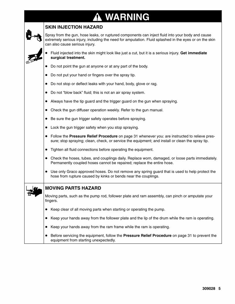
WARNINGSKIN INJECTION HAZARD
Spray from the gun, hose leaks, or ruptured components can inject fluid into your body and causeextremely serious injury, including the need for amputation. Fluid splashed in the eyes or on the skincan also cause serious injury.
� Fluid injected into the skin might look like just a cut, but it is a serious injury. Get immediate surgical treatment.
� Do not point the gun at anyone or at any part of the body.
� Do not put your hand or fingers over the spray tip.
� Do not stop or deflect leaks with your hand, body, glove or rag.
� Do not “blow back” fluid; this is not an air spray system.
� Always have the tip guard and the trigger guard on the gun when spraying.
� Check the gun diffuser operation weekly. Refer to the gun manual.
� Be sure the gun trigger safety operates before spraying.
� Lock the gun trigger safety when you stop spraying.
� Follow the Pressure Relief Procedure on page 31 whenever you: are instructed to relieve pres-sure; stop spraying; clean, check, or service the equipment; and install or clean the spray tip.
� Tighten all fluid connections before operating the equipment.
� Check the hoses, tubes, and couplings daily. Replace worn, damaged, or loose parts immediately.Permanently coupled hoses cannot be repaired; replace the entire hose.
� Use only Graco approved hoses. Do not remove any spring guard that is used to help protect thehose from rupture caused by kinks or bends near the couplings.
MOVING PARTS HAZARD
Moving parts, such as the pump rod, follower plate and ram assembly, can pinch or amputate yourfingers.
� Keep clear of all moving parts when starting or operating the pump.
� Keep your hands away from the follower plate and the lip of the drum while the ram is operating.
� Keep your hands away from the ram frame while the ram is operating.
� Before servicing the equipment, follow the Pressure Relief Procedure on page 31 to prevent theequipment from starting unexpectedly.
6 309028
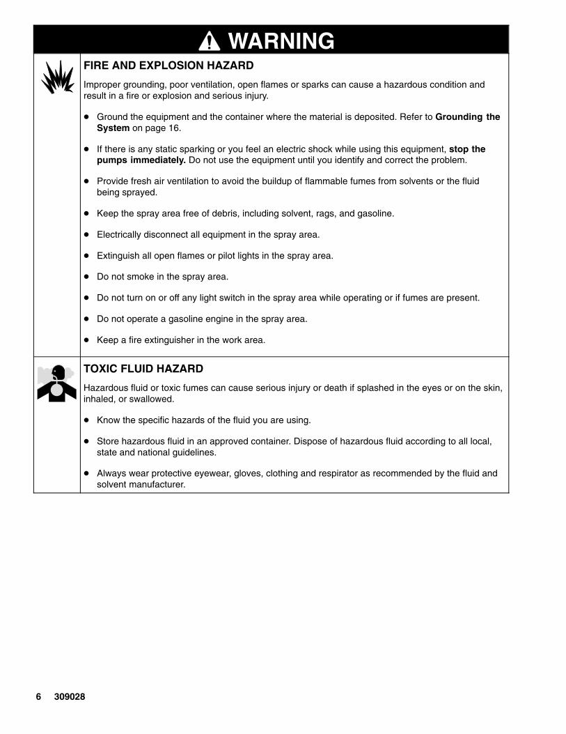
WARNINGFIRE AND EXPLOSION HAZARD
Improper grounding, poor ventilation, open flames or sparks can cause a hazardous condition andresult in a fire or explosion and serious injury.
� Ground the equipment and the container where the material is deposited. Refer to Grounding theSystem on page 16.
� If there is any static sparking or you feel an electric shock while using this equipment, stop thepumps immediately. Do not use the equipment until you identify and correct the problem.
� Provide fresh air ventilation to avoid the buildup of flammable fumes from solvents or the fluidbeing sprayed.
� Keep the spray area free of debris, including solvent, rags, and gasoline.
� Electrically disconnect all equipment in the spray area.
� Extinguish all open flames or pilot lights in the spray area.
� Do not smoke in the spray area.
� Do not turn on or off any light switch in the spray area while operating or if fumes are present.
� Do not operate a gasoline engine in the spray area.
� Keep a fire extinguisher in the work area.
TOXIC FLUID HAZARD
Hazardous fluid or toxic fumes can cause serious injury or death if splashed in the eyes or on the skin,inhaled, or swallowed.
� Know the specific hazards of the fluid you are using.
� Store hazardous fluid in an approved container. Dispose of hazardous fluid according to all local,state and national guidelines.
� Always wear protective eyewear, gloves, clothing and respirator as recommended by the fluid andsolvent manufacturer.
309028 7
Uncrating the SystemThe Uni-Drum supply system was carefully packagedfor shipment by Graco. When the system arrives,perform the following procedure to uncrate the system.
WARNINGEQUIPMENT MOVING HAZARDRemoving the unit off the pallet without followingthe uncrating procedure will damage the equip-ment.
To uncrate the system, do the following:
1. Inspect the crate carefully for shipping damage.Contact the carrier promptly if damage is discov-ered.
2. Remove the plywood sides and top of the crate.
3. Inspect the contents carefully. There should not beany loose or damaged parts.
4. Compare the packing slip against all items in-cluded in the crate. Report any shortages or otherinspection problems immediately.
5. Remove the band straps that hold the Uni-Drum tothe pallet.
NOTE: The Uni-Drum is ready for installation. Beforeinstalling the system, read the “General Description”section to become familiar with the system compo-nents.
OverviewInstallation Overview
The location of the Uni-Drum should allow for easyloading and unloading of the 300 gallon (1200 liter)magnadrum or other tote drums with either a forklifttruck or pallet-jack hand truck.
The Uni-Drum supply system must be leveled andmounted on a horizontal floor. An unleveled conditioncan keep the Uni-Drum from operating properly.
Anchor the frame’s four foot pads securely to the floor.The anchor bolts should be sized with sufficient safetyfactor to withstand the downward force of the followerplate and other objects that can push the frame off thefloor.
Operation OverviewThe Uni-Drum is a supply system that evacuates fluidsfrom a 300 gallon (1200 liter) magnadrum or other totedrums.
Each Uni-Drum includes two Graco air motors and dis-placement pumps, a ram assembly with a followerplate, a pneumatic layout panel that controls the aircomponents and a junction box panel that connectswith an electrical controller (supplied by the customer).
In short, the operator places the magnadrum inside theframe with the follower plate placed directly on top ofthe material. Locally, the system can be operated us-ing pneumatic layout panel. Remotely, the system canbe operated using signals through the junction boxpanel.
Two displacement pumps evacuate material out ofeach magnadrum. After removing the empty drumfrom the system, the operator repeats the evacuationprocess when another drum is ready for evacuation.
8 309028
General DescriptionSystem ComponentsA general description of the Uni-Drum supply systemhelps the installers and operators become familiar withthe system components. Contact your Graco distribu-tor for help in choosing accessories to suit your partic-ular needs.
Before you install the system you should be familiarwith the parts described in the following paragraphs.
Fig. 1 shows the typical Uni-Drum supply systemequipped with Premier� air motors. The following listidentifies the Uni-Drum system components:
Ref. DescriptionA Left hand (LH) supply unitB Right hand (RH) supply unitC Dura-Flo� 1800 pumps with Premier� air
motors (2 units)D Ram assembly and follower plateE Main air inletF 3/8 npt air filterG Pneumatic layout panelH Junction box panelJ Drum lid holders
� Uni-Drum System (A) is usually setup to alternatethe material supply operation between the left hand(LH) and right hand (RH) supply units, which isaccomplished using a combination of robotic soft-ware programming (provided by others) and manu-al operators. Drum changeovers occur after thefollower plate has reached its preset low limit levelin the drum. Alternating between supply unitseliminates the downtime that is usually expendedunloading an empty drum and reloading a full drum.
– LH pump supply unit (A) accommodates one300 gallon (1200 liter) drum. The LH supplyunit has a local pneumatic layout panel andjunction box panel.
– RH pump supply unit (B) accommodates one300 gallon (1200 liter) drum. The RH supplyunit has a local pneumatic layout panel andjunction box panel.

309028 9
General Description
Fig. 1A – Left Hand Unit
Left Hand Models
246981
248306
249339
B – Right Hand Unit
Right Hand Models
246982
248307
249340
C C
DD
E E
FF
GG
HH
HH
J
TI0137
Ti4625a
Ti4624a

10 309028
General Description
Fig. 2A – Left Hand Unit
Left Hand Models
246981
248306
249339
232729
232839
246921
253676
249152
234972
249341
258910
258956
255666
24H017
B – Right Hand Unit
Right Hand Models
246982
248307
249340
232730
232840
246922
253677
249153
234973
249342
258911
258957
255665
24H016
C C
DD
E E
FF
GG
H H
HH
J
TI013

309028 11
General DescriptionSystem Components (continued)
NOTE: The paragraphs that follow describe the com-ponents for the LH pump supply unit only. The descrip-tions are the same for the RH pump supply unit.
� The two Dura-Flo� 1800 Pumps (C) have Pre-mier� air motors. The pumps evacuate materialfrom the drum.
� The follower plate (D) is connected to the ramassembly and is designed to apply an even amountof pressure to the material in the drum. With thefollower plate in its raised position, the operatormoves a drum inside the frame. The follower plateis lowered directly on top of the material in thedrum. When pressure is applied to the followerplate, the material is pumped out of the drumthrough hoses, which are attached to the pumpoutlet ports. When the drum is empty, the operatorraises the follower plate, removes the empty drum.The process is repeated when another drum isready to be unloaded.
� 3/8 in. npt air filter (F) filters air to the pneumaticlayout panel. The 5 micron filter removes particles,such as dust, moisture, foreign matter and othercontaminants from the compressed air.
Pneumatic Layout Panel (G)
The pneumatic layout panel includes the followingsystem components. For more information, refer to thePneumatic Diagram on page 76.
� Main Air Inlet Valve (at E) is used to open or shutoffthe air supply to the entire supply unit.
� Pump No. 1 Air Regulator controls pump speed andoutlet pressure for pump no. 1 by adjusting the airpressure to the pump.
� Pump No. 1 Pressure Gauge displays the amountof air pressure supplied to pump no. 1.
� Pump No. 2 Air Regulator controls pump speed andoutlet pressure for pump no. 2 by adjusting the airpressure to the pump.
� Pump No. 2 Pressure Gauge displays the amountof air pressure supplied to pump no. 2.
� Follower Vent Open Valve switch is activated toopen the vent to relieve container pressure.
� Ram Up pushbutton turns on air pressure to raisethe follower plate.
� The Ram Position Switch performs the followingthree functions:
– Place the switch in the RAISE position to raisethe follower plate.
– Place the switch in the HOLD position to holdthe follower plate in the current position.
– Place the switch in the LOWER position tolower the follower plate.
Junction Box Panel (H)
The junction box panel includes the following systemcomponents. For additional information, refer to theElectrical Diagram on page 75.
� System Pressurized lamp is lit when air pressure issupplied to the system; the lamp is extinguishedwhen the air supply is depressurized. This occursafter the Pump On button has been pushed and thepumps turned on.
� Pump Active lamp is lit when the air supply isturned on to the pumps; the lamp is extinguishedwhen the pumps are inactive, thus turned off. Thisis activated by the Pump On pushbutton.
� Air Pressure On lamp is lit when air pressure to thesystem is turned on; the lamp is extinguished whenair pressure to the system is shutoff.
� Ram Ready lamp is lit when the drum is in position;the lamp is extinguished when the drum is not inposition.
� Pump Ready lamp is lit when the pumps are primedand ready for operation; the lamp is extinguishedwhen the pumps are not ready for operation.
� Prime Pump pushbutton turns on the pumps, forpriming. When the pumps are primed, the PumpReady lamp turns on. The switch is not used whenthe Pump Ready lamp is lit. The Pump Active lightwill blink.
� Pump Reset pushbutton resets the pumps to anactive state. When the pumps are reset, the PumpActive lamp turns off. The switch is not used whenthe Pump Active lamp is lit. The Pump Ready lightis on.
� Pump On pushbutton turns the pumps on and off.When the pumps are turned on, the Pump Activelamp also turns on. When the pumps are turned off,the Pump Active lamp also turns off.
� Bulk Supply Depressurization button opens thedepressurization valve to lower the fluid pressure.
� Auto Mode On/Off switch puts the system into orout of automatic operation.
12 309028
InstallationThe installation procedures in this section are intendedto serve as a guide for installing the Uni-Drum system.If you need more information, contact your Gracodistributor.
NOTE: When raising and lowering the follower plate,be sure that the unit is unobstructed overhead to avoidinterference with other objects.
The installation procedure includes:
� Preparing the site
� Selecting a location for the Uni-Drum
� Preparing to install the Uni-Drum
� Installing the Uni-Drum
� Connecting power to the junction box
� Grounding the system
� Checking resistance between the junction box andthe true earth ground
� Connecting air supply lines to Uni-Drum
Preparing the Site
Ensure that you have an adequate compressed airsupply. Refer to the applicable instruction manual listedin Related Publications on page 82 to find the airconsumption of your pump. Approximately 450 cfm at80 psi is required to operate the pumps at the maxi-mum rate.
Keep the site clear of any obstacles or debris thatcould interfere with the installer’s and operator’s move-ment.
Selecting a Location for the Uni-Drum
Refer to Technical Data on page 78 for ram mountingand clearance dimensions.
When selecting a location for the Uni-Drum, keep thefollowing in mind:
1. There should be sufficient space for installing,servicing, and using the equipment.
� Select an accessible location for the system.There must be sufficient space around thesystem for maintenance.
� Select a convenient location for the equipment.Check that there is sufficient overhead clear-ance for the pump and ram when the ram is inthe fully raised position. Make sure the airregulators for the pumps and follower plate arefully accessible.
� Make sure the air source for the PLC controlpanel and shutoff valves are fully accessible.
� Make sure there is easy and safe access to anappropriate pneumatic source. Graco recom-mends a minimum of 3 feet (0.91 m) of openspace in front of the control panel.
2. Make sure that you will be able to level the base ofthe ram using metal shims.
Preparing to Install the System
Before installing the system:
� See component manuals for specific data on com-ponent requirements. Data presented here pertainsto the system only.
� Have all system and subassembly documentationavailable during installation.
� Be sure that all non-Graco supplied hoses areadequately sized and pressure-rated to meet thesystem requirements.

309028 13
InstallationInstalling the Uni-Drum
To install the Uni-Drum, follow the procedure below.Refer to Technical Data on page 78 for ram mountingand clearance dimensions.
1. Using equipment such as a forklift or handtruck,move the Uni-Drum into place on the floor. Re-move the shipping pallet.
2. Level the Uni-Drum, using metal shims.
3. Using the holes in the base as a guide, drill holesfor 13 mm (1/2 in.) anchors.
4. Bolt the Uni-Drum to the floor using anchors thatare long enough to prevent the unit from tipping.Refer to page 78 for more information.
WARNINGEQUIPMENT MISUSE HAZARDThe Uni-Drum system is shipped withevery major component already attachedand weighs approx. 3950 lb (1792 kg).
The Uni-Drum system should never be moved orlifted by one person. To prevent equipment damageor personal injury, engage an adequate number ofpersonnel and use a forklift, hand truck, and sup-port devices, such as a hoist when moving andinstalling the Uni-Drum system.
CAUTIONBe sure to use as many people as needed when theframe is being lifted or moved. Exercise care to avoidjarring, dropping, or tilting the frame while it is beingmoved to its installed location to prevent injury orproperty damage.

14 309028
InstallationConnecting Power to the Junction Box
Perform the following procedure to connect the powerto the junction box panel.
WARNINGELECTRIC SHOCK HAZARDDo not connect the junction box panel toa power source unless you are a trainedelectrician. Failure to follow standard
procedures or to observe the necessary precau-tions could result in serious bodily injury or equip-ment damage.
CAUTIONIf power and grounding connections are not doneproperly, the equipment may be damaged and thewarranty will be voided.
NOTE: Have a qualified electrician connect the junc-tion box to a grounded electrical source that has thefollowing required service ratings:
Description Requirements
Voltage: 120 Vac 24 Vdc
Hz: 50/60 –
Phase: 1 –
Circuit Breaker 5 Amp 5 Amp
To connect the junction box panel to the electricalsource, do the following:
WARNINGELECTROCUTION HAZARDInstalling and servicing this equipmentrequires access to parts which couldcause an electric shock or other serious
injury. Have only qualified electricians access thecontrol assembly.
1. Shut off system power at the main circuit breaker.
2. Remove the cover from the junction box panel.
3. Locate the PLC power terminals KS102 andKS100 on the terminal strip inside the junction boxpanel. See Fig. 3. For more information, refer toElectrical Diagram on page 75 .
4. Using the upper wire duct on the left-hand side ofthe junction box panel, string two 14 AWG wiresinside the box from the electrical power source.
5. Connect the two 14 AWG wires to power terminalsKS102 (L1, hot) and KS100 (L2, neutral) in thejunction box panel.
6. Seal the area where wires entered the junction boxpanel.
7. Replace the cover on the junction box panel.

309028 15
InstallationConnecting Power to the Junction Box (continued)
Fig. 3
Terminals
SPARESPARESPARESPARESPARESPARESPARESPARESPARESPAREFU136FU143SUP136SUP144154115111481143114111361134112911271124112211191117111411121108110011001100110231003 (31) TOTALType 0290.011.25ENTRELEC
ISOLATION BLOCKS
(KNIFE SWITCH DISC.
KS100 10011002
KS102 1021 1022(2) TOTALType1492–WKD3TP
Strain Relief
Fuse Blocks Terminals
Wire Way
Enclosure
Ground Lug
TI0205b

16 309028
InstallationGrounding the System
WARNINGFIRE AND EXPLOSION HAZARDBefore operating the pump, ground thesystem as explained below. Also readthe section FIRE AND EXPLOSIONHAZARD on page 6.
1. Pump: use a ground wire and clamp. See Fig. 4.Loosen the grounding lug locknut (W) and washer(X). Insert one end of a 12 ga (1.5 mm�) minimumground wire (Y) into the slot in lug (Z) and tightenthe locknut securely. Connect the other end of thewire to a true earth ground. For a ground wire andclamp, order Part No. 237569.
W
Y
X
Z
Fig. 40720
2. Air and fluid hoses: Use only electrically conduc-tive hoses.
3. Air compressor: follow manufacturer’s recommen-dations.
4. Spray gun or dispensing valve: ground throughconnection to a properly grounded fluid hose andpump.
5. Object being sprayed: follow your local code.
6. Fluid supply drum: follow your local code.
7. Solvent pails used when flushing: follow your localcode. Use only metal pails, which are conductive,placed on a grounded surface. Do not place thepail on a nonconductive surface, such as paper orcardboard, which interrupts the grounding continu-ity.
8. To maintain grounding continuity when flushing orrelieving pressure, hold a metal part of the spraygun firmly to the side of a grounded metal pail,then trigger the gun.
Checking the Resistance Between thePumps and the True Earth Ground
Have a qualified electrician check the resistancebetween the each pump and the true earth ground.The resistance must be less than 29 megohms. If theresistance is greater than 0.25 ohms, a differentground site may be required. Do not operate thesystem until the problem is corrected.
NOTE: Use a meter that is capable of measuringresistance at this level.
WARNINGFIRE, EXPLOSION, AND ELECTRICSHOCK HAZARDTo reduce the risk of fire, explosion, orelectric shock the resistance betweenthe supply unit components and trueearth ground must be less than 0.25ohms.

309028 17
InstallationConnecting the Air Supply Lines to the Uni-Drum
Perform the following procedure to connect the inputair supply lines to the Uni-Drum system.
Connecting Air Supply Lines to the Supply Units
To connect the main air supply line to the LH and RHsupply units, do the following:
WARNINGTo reduce the risk of overpressurizing your system,which could result in component rupture and causeserious injury, never exceed the specified maxi-mum incoming air pressure to the pumps (see theTechnical Data on page 78).
NOTE: Have a qualified technician connect bothsupply units to an air supply source that has the follow-ing required ratings:
Description Requirements
Inlet Port Size: 1 in. npt(f)
Air Volume: 450 cfm (maximum)
Input Air: 80 psi (5.5 bar, 0.55 MPa)
1. Check the air supply to ensure that it is properlysized and pressure-rated for this system.
2. Connect the air supply line to the 1 in. npt main airinlet.
Fig. 5
Main Air Inlet
Main Air Shutoff Valve
Air Line to Pneumatic Panel
Main Air Filter
Air Line to Pump Air Manifold
Pump Air Manifold
Pilot Valve
AirLIne Lubricator
Air Supply Lines to Pumps
TI0198
TI0204

18 309028
InstallationConnecting Output Hose to the Pumps
This procedure describes how to connect the fluidoutput hoses to the two pumps. It is the customer’sresponsibility to have the fluid supply hose alreadyinstalled and ready for connection to the pumps.
NOTE: For more information about the pumps, seeRelated Publications on page 82 for the pump in-struction manuals.
CAUTIONThere must be a minimum of 10 feet (3 m) of fluidsupply hose on the outlet to prevent damage to theunit.
NOTE: The fluid supply hose must move freely withoutkinking when the pumps move up and down.
Check the fluid supply hose to ensure it is properlysized and pressure-rated for this system. Use onlyelectrically conductive hoses. The fluid supply hoseshould have spring guards on both ends. Connect thefluid supply hose to the fluid manifold outlet.
Fig. 6
Fluid Manifold
Fluid Outlet
Fluid Supply Hose
TI0139

309028 19
OperationThe operation procedures include:
� Prepare the operator
� Overview
� Junction box panel switches and indicators
� Pneumatic layout panel switches and indicators
� Initial system startup procedure
� Daily system startup
� System shutdown
� Operation modes for the pumps
� Pressure relief procedure
� Air motor icing
� Preventive maintenance schedule
� System operation procedures
Prepare the Operator
All persons who operate the equipment must betrained in the safe, efficient operation of all systemcomponents as well as the proper handling of all fluids.All operators must thoroughly read all instructionmanuals, tags, and labels before operating the equip-ment.
Overview
The Uni-Drum supply system uses two air drivenreciprocating pumps on the LH supply unit and two airdriven reciprocating pumps on the RH supply unit.Each supply unit pumps material from a 300 gallon(1200 liter) drum.
General Functional Description
The LH and RH supply units can operate at the sametime or as independent units. Generally, the Uni-Drumsystem is setup to operate as redundant units. Thismeans that the RH unit is held in reserve on standbyuntil the drum underneath the LH unit has been emp-tied, and vice versa.
Operating a redundant system allows the operator tomaintain a continuous supply of material withoutinterruption. The operator is afforded sufficient time toreplace an empty drum at one supply unit while thedrum at the other supply unit is being emptied.
System Startup
There are a series of steps that must be followed insequential order to startup the system.
System Operation
Depending upon the system setup, at any time duringoperation, the operator can:
� Stop the pumps and relieve ram pressure at the LHsupply unit.
� Stop the pumps and relieve ram pressure at the RHsupply unit.
� Shutdown the system.
At the supply unit, the follower plate must be raised toload the drum into the supply unit. The follower plate islowered by the operator directly into the drum. Thepumps are turned on, the follower plate is pressurized,and material is pumped from the drum through theoutlet ports on the pumps via a supply hose to one ormore targeted applications.
Supply Unit Operation
The Uni-Drum supply system can be setup to alternatebetween the LH and RH supply units. This dual supplysystem setup (controlled by others) virtually eliminatesmaterial replenishment downtime.
The Uni-Drum supply system allows the operator toload the material drum into the RH supply unit whilethe LH supply unit drum is being emptied. When thesupply unit changeover occurs, the operator unloadsthe empty drum at the LH supply unit while the RHsupply unit drum is being emptied. The cycle is re-peated as many times as needed.
System Shutdown
For system shutdown, the operator turns off the pumpsand depressurizes the system. Depending upon thetype of material, the operator may choose to raise thefollower plate from the drum or keep the follower platelowered in the drum to prevent the material from beingcontaminated. Some materials will harden or congealwhen exposed to air or used past their shelf life. Mate-rial should be kept covered when it is not being usedand uncovered when it is ready to use.

20 309028
OperationJunction Box Panel Switches and Indicators
Use the table and Fig. 7 when operating the switches and reading the indicator on the junction box panel.
Button/Switch What it Does
PRIME PUMP pushbutton � Primes both displacement pumps with material, making thepumps ready to operate.
� Lights PUMP READY light.
PUMP RESET pushbutton � Restarts the pumps after the pumps were turned off.
� Lights PUMP ACTIVE light
PUMP ON pushbutton � Activates the pumps.
� Deactivates the pumps.
Bulk Supply Depressurizationpushbutton
� Opens the depressurization valve to lower the fluid supplypressure.
AUTO MODE ON/OFF switch � Places fluid dispensing system into Automatic or Manualmode.
Indicator IndicatorLight is
Meaning
SYSTEMPRESSURIZED li ht
ON System is pressurized.PRESSURIZED light OFF System is depressurized.
PUMP ACTIVE light ON Pumps are active; air is available to the pumps.
OFF Pumps are inactive; air is unavailable to the pumps.
AIR PRESSURE ONli ht
ON Air pressure is available to the pumps for use.light OFF Air pressure is not available to the pumps for use.
RAM READY light ON Follower plate is ready for use.
OFF Follower plate is not ready for use.
PUMP READY light ON Pumps are primed and ready to use.
OFF Pumps are not ready to use.
309028 21
OperationJunction Box Panel Switches and Indicators (continued)
Fig. 7
195320 and 119773 Panel ShownTI0203

22 309028
OperationPneumatic Layout Panel Switches and Indicators
Use the table and Fig. 8 when operating the switches and reading the indicators on the pneumatic layout panel.
Ref Button/Switch/Gauge What it Does
A PUMP NO. 1 PRESSURE Air Gauge Indicates the air outlet pressure setting from pump no. 1.
B PUMP NO. 2 PRESSURE Air Gauge Indicates the air outlet pressure setting from pump no. 2.
C PUMP NO. 1 REGULATOR Control Knob Controls pump speed and outlet pressure by adjustingthe air pressure to pump no. 1.
D FOLLOWER VENT Directional Valve Opens and closes the vent that relieves air pressurefrom the follower plate assembly.
E PUMP NO. 2 REGULATOR Control Knob Controls pump speed and outlet pressure by adjustingthe air pressure to pump no. 2.
F RAM UP Pushbutton Raises the follower plate.
G RAM POSITIONS it h
RAISE Allows the follower plate to raise.Switch HOLD Holds the follower plate in the current position.
LOWER Lowers the follower plate.
H Air Inlet Valve Opens air supply line to the unit.

309028 23
Operation
Fig. 8
A
B
C
D E
F
G
H
195319 Panel Shown
TI0202
FOLLOWER VENTAUTO OPEN

24 309028
OperationFlushing the System Before Initial Use
Flushing the system before its initial use can preventmaterial contamination, which may cause the materialto fail or perform poorly.
CAUTIONFlush the system before performing the initialmaterial loading procedure. The system was facto-ry-tested using a light soluble oil, a soybean oil, orsome other oil as tagged. Flush the system to avoidcontaminating the material that has been designatedfor initial material loading.
To flush the system, perform the following procedure:
1. Select the material for the initial material load.
2. Verify whether the factory-test oil and the initialmaterial load are compatible:
a. If the two substances are compatible, omit theremaining steps in this procedure and performthe Initial System Startup Procedure onpage 25.
b. If the two substances are incompatible, per-form the remaining steps in this procedure toflush the system.
WARNINGUse fluids and solvents that are chemically compat-ible with the equipment wetted parts. See theTechnical Data sections of all the equipmentmanuals. Always read the material manufacturer’sliterature before using fluid or solvent in this pump.
3. Select a drum containing a compatible materialthat can dissolve, clean, and eliminate the factory-test oil from the system. If necessary, check withthe material supplier for a recommended flush ma-terial.
4. Before flushing, be sure the entire system andflushing drums are properly grounded. Refer toGround the System, on page 16.
5. Perform steps 8 through 14 of the Initial SystemStartup Procedure on page 25 to load the drumcontaining the solvent.
6. Run the flush material through the system forapproximately 1 to 2 minutes.
7. Remove the drum containing the flush material.
Adjusting the Lid Holder Before Initial Use
1. Adjust the lower lid holder channel as low as it willgo on the side of the ram post. The channel shouldbe 1 in. (25 mm) higher from the floor in the frontcompared to the back.
2. Loosen the upper lid holder channel. place the lidin the center of the lower channel. Lower the upperchannel until it contacts the lid. Tilt the rear of theupper channel down 1/2 to 1 in. (13 to 25 mm) andtighten all bolts.
3. The lid should roll in and out from the front and notroll out the rear.

309028 25
OperationInitial System Startup Procedure
WARNINGPRESSURIZED FLUID HAZARD To reduce the risk of serious bodily inju-ry, such as fluid injection or splashingfluid in the eyes or on the skin, alwayswear eye protection and protective cloth-ing when installing, operating, or servic-ing this dispensing system.
MOVING PARTS HAZARDMoving equipment parts can cause per-sonal injury, including severing of handsor fingers. Make sure all personnel areclear of moving parts before operatingthe equipment.
CAUTIONThe use of a non-compatible lubricant can causematerial contamination or inadequate perfor-mance. Use only a lubricant compatible with the ma-terial to be pumped. Check with the material supplierfor a recommended lubricant.
To help avoid damage to equipment, do not use adrum of material that has been dented or otherwisedamaged; damage to the follower plate wiper mayresult.
WARNINGPRESSURIZED EQUIPMENT HAZARDTo reduce risk of injury or equipmentdamage:
� Make sure all material hose connec-tions are secure.
� Do not pressurize the system untilyou have verified the system is readyand it is safe to do so.
Settings for Initial System Startup
The initial system startup procedure contains thechecklist of settings, adjustments, and proceduralsteps that must be completed before the system isready for daily operation.
NOTE: Complete the startup procedure for the LHsupply unit first. Then, repeat the startup procedure forthe RH supply unit.
Perform the initial system startup procedure as follows:
1. Check all material hoses and fittings to ensuretightness and to prevent any material leakage.
2. Check all system air lines. Make sure that all rout-ing of air lines will not interfere with any movingcomponents within the system.
3. Fill the packing nut/wet cup on both pumps 1/3 fullwith Graco throat seal liquid (p/n 206995). Refer toinstruction manual 308147 or 308148 for details.
4. At the pneumatic layout panel, open the main airinlet valve at the LH supply unit, making air pres-sure available to the unit. See Fig. 5.
5. Adjust both pump main air regulators to 0 psi.
6. Follower Vent switch should be in AUTO position.
7. Set the RAM POSITION switch to RAISE.
8. Press the RAM UP valve switch to raise the follow-er plate above the height of the material drum tobe used.
9. Set the RAM POSITION switch to HOLD.

26 309028
OperationInitial System Startup Procedure (continued)
Load Material
10. Roll a drum into the supply unit under the elevatedfollower plate.
NOTE: Whenever a drum change is required, removethe cover from the drum of new material by holding itlevel and lifting it straight up. Tipping the cover mayallow accumulated dirt to spill into the drum, whichmay result in damage to the material and equipment.
11. IMPORTANT: Lubricate the follower plate wiperwith a lubricant that is compatible with the materialto be pumped. Check with your material supplierfor compatibility.
NOTE: Before lowering the follower plate assemblyinto the drum, make sure that nothing is between thefollower plate and the drum, or between the ram tie barand the top of the ram posts.
12. Remove bleed sticks at the base of each pump.
13. Lower the follower plate as follows:
a. Set the Ram Position selector to LOWER.
b. Lower the follower plate until the material isevident in the bleedstick ports.
c. Set the Ram Position selector to HOLD.
d. Replace the bleedsticks.
e. Set the Ram Position selector to LOWER.
14. Close both pump #1 and pump #2 inlet valves (lo-cated on top of air motor).
15. To prime the pump, press the PRIME PUMPbutton.
16. Set the pump air pressure to 30 psi.
17. Check that the AIR PRESS. ON indicator is lit.
18. Use a catch device to bleed the pump. Slowlyopen Pump No. 1 bleeder valve. Back off theadjustment screw several turns; do not remove thescrew.
19. Slowly open the bleed-type air valve to the airmotor. Allow the pump to cycle slowly until all airescapes and material flows free of air from thebleeder valve.
20. Close the bleed-type air valve and pump bleedervalve.
21. Repeat these steps for Pump No. 2.
NOTE:
� If the pump does not prime properly, which mayoccur with heavier, high viscosity fluids, increasethe air pressure to the ram.
� If fluid is forced out around the top wiper, rampressure is too high; decrease the air pressure tothe ram.
� Ram pressure adjustments may be carried outusing the dual regulator inside the pneumaticpanel, where the upper regulator knob controls thedownward pressure of the ram, and the lowerregulator knob controls the upward pressure of theram.
22. After closing the bleed valve, return Pump No. 1and 2 regulator to its normal pump pressure set-ting.
23. Open the air motor ball valves.
24. Open the ball valve in the outlet manifold fromPump No. 1 and 2.
25. Remove the waste containers, clean up any spilledmaterial, and dispose of the waste material proper-ly.
26. Press the PUMP RESET button to restore thesystem to operation.
27. Check that the following indicators are lit:
� SYSTEM PRESSURIZED
� AIR PRESS. ON
� RAM READY
� PUMP READY
309028 27
OperationInitial System Startup Procedure (continued)
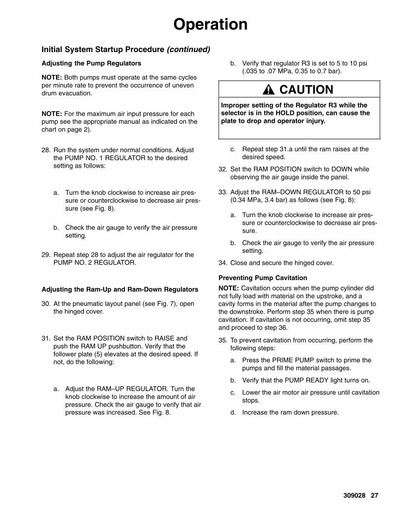
Adjusting the Pump Regulators
NOTE: Both pumps must operate at the same cyclesper minute rate to prevent the occurrence of unevendrum evacuation.
NOTE: For the maximum air input pressure for eachpump see the appropriate manual as indicated on thechart on page 2).
28. Run the system under normal conditions. Adjustthe PUMP NO. 1 REGULATOR to the desiredsetting as follows:
a. Turn the knob clockwise to increase air pres-sure or counterclockwise to decrease air pres-sure (see Fig. 8).
b. Check the air gauge to verify the air pressuresetting.
29. Repeat step 28 to adjust the air regulator for thePUMP NO. 2 REGULATOR.
Adjusting the Ram-Up and Ram-Down Regulators
30. At the pneumatic layout panel (see Fig. 7), openthe hinged cover.
31. Set the RAM POSITION switch to RAISE andpush the RAM UP pushbutton. Verify that thefollower plate (5) elevates at the desired speed. Ifnot, do the following:
a. Adjust the RAM–UP REGULATOR. Turn theknob clockwise to increase the amount of airpressure. Check the air gauge to verify that airpressure was increased. See Fig. 8.
b. Verify that regulator R3 is set to 5 to 10 psi(.035 to .07 MPa, 0.35 to 0.7 bar).
CAUTIONImproper setting of the Regulator R3 while theselector is in the HOLD position, can cause theplate to drop and operator injury.
c. Repeat step 31.a until the ram raises at thedesired speed.
32. Set the RAM POSITION switch to DOWN whileobserving the air gauge inside the panel.
33. Adjust the RAM–DOWN REGULATOR to 50 psi(0.34 MPa, 3.4 bar) as follows (see Fig. 8):
a. Turn the knob clockwise to increase air pres-sure or counterclockwise to decrease air pres-sure.
b. Check the air gauge to verify the air pressuresetting.
34. Close and secure the hinged cover.
Preventing Pump Cavitation
NOTE: Cavitation occurs when the pump cylinder didnot fully load with material on the upstroke, and acavity forms in the material after the pump changes tothe downstroke. Perform step 35 when there is pumpcavitation. If cavitation is not occurring, omit step 35and proceed to step 36.
35. To prevent cavitation from occurring, perform thefollowing steps:
a. Press the PRIME PUMP switch to prime thepumps and fill the material passages.
b. Verify that the PUMP READY light turns on.
c. Lower the air motor air pressure until cavitationstops.
d. Increase the ram down pressure.

28 309028
Operation
Fig. 9
Ram DownRegulator
Ram UpRegulator
Regulator R3
9327A

309028 29
OperationInitial System Startup Procedure (continued)
Adjusting the Low Limit SwitchNOTE: When the low limit switch is activated, thepumps are normally turned off automatically by acustomer-supplied control, and a second set of pumpsbegin pumping.
36. Adjust the low limit switch as follows:
a. At the junction box panel (see Fig. 7), set theRAM POSITION switch to LOWER, allowingthe follower plate to activate the lower limitswitch.
b. Verify that the follower plate lowers to the limitset point: a level between 1–4 in. (25.4–101.6mm) from the bottom of the drum.
c. Adjust the low limit switch to activate at thelevel defined in step 36.b See Fig. 10.
Fig. 10
TI0200
1 to 4 in. (25.4 to 101.6 mm)
Limit Switches
Pin 1
Pin 3
Pin 5
Pin 2
Pin 4

30 309028
OperationDaily System Startup
This procedure is normally provided by the integrator.
System Shutdown
This procedure is normally provided by the integrator.
Emergency Stop
When an emergency stop is required, do the following:
Stopping the System
1. To stop the system, close the main air inlet supply(see Fig. 11) to the supply unit.
Restarting the System2. To restart the system, do the following:
a. Open the main air valve to the supply unit (seeFig. 11).
b. At the junction box panel, press the PUMPRESET switch which restarts the pumps afterthe pumps were turned off (refer to Fig. 7).
Fig. 11
Main Air Inlet
Main Air Valve
TI0198

309028 31
OperationPressure Relief Procedure
This procedure describes how to relieve pressure fromthe system. Use this procedure whenever you shutoffthe pumps and before checking or adjusting any partof the system, to reduce the risk of serious injury.
WARNINGMOVING PARTS HAZARDFollow the Pressure Relief Procedurebelow before checking or repairing thefollower plate or any other part of the
system and when shutting down the system. Keephands and fingers away from the follower plate,pump inlets, and the drum when raising or loweringthe follower plate to reduce the risk of pinching oramputating hands or fingers.
During operation, also keep hands and fingersaway from limit switches to reduce the risk ofpinching or amputating hands or fingers.
WARNINGSKIN INJECTION HAZARDThe system pressure must be manuallyrelieved to prevent the system fromstarting or spraying accidentally. Material
under high pressure can be injected through theskin and cause serious injury. To reduce the risk ofan injury from injection, splashing fluid, movingparts, follow the Pressure Relief Procedurewhenever you:
� are instructed to relieve the pressure
� stop dispensing material
� check or service any of the system equipment
� install or clean the follower plate wipers.
To relieve pressure on the follower plate and in thepumps, perform the following procedure:
At the pneumatic layout panel, do the following:
1. Close the main air inlet valve (see Fig. 11).
2. Open any downstream fluid valves, such as theball seat applicators on the ram assemblies, thatmay be part of the system.
3. Press the depressurization button on the electricalpanel.
4. After the pressure is relieved from the followerplate, raise the follower plate by setting the RAMPOSITION switch to the RAISE position.
Fig. 12TI0195
Ball SeatApplicator
Preventive Maintenance ScheduleThe operating conditions of your particular systemdetermine how often maintenance is required. Estab-lish a preventive maintenance schedule by recordingwhen and what kind of maintenance is needed, andthen determine a regular schedule for checking yoursystem.

32 309028
OperationChanging Empty Drums
NOTE: After the automatic pump crossover has takenplace, immediately replace the empty drum with a new,full drum. If both Uni-Drums become empty at thesame time:
� Material will stop being delivered to the dispenser
� Air may enter the supply hose or pipe header
� Pump runaway could occur, resulting in damage tothe pumps.
Drum Changing Procedure
To remove an empty drum and load a new, full drum:
1. Verify that the two front and rear drum clamps areengaged on the Uni-Drum ram base.
2. Check that the pump air is turned off. On thejunction box panel the PUMP ACTIVE and PUMPREADY indicators are not lit.
3. Check that the RAM UP air regulator is set to 60psi (maximum).
4. Close the two ball valves at the outlet manifold atthe rear of the Uni-Drums.
5. To raise the follower plate:
a. Set the RAM POSITION control to RAISE,then wait 5 seconds.
NOTE: If RAM UP button is pushed within 5 seconds,the vent valves may open before the pressure underthe follower plate is relieved causing the material tobleed past the vents.
b. Push and hold the RAM UP button as thefollower plate slowly rises.
6. With the ram raised and the RAM POSITIONcontrol set to RAISE, pull the drum clamps backand remove the empty drum, using a suitablelifting device.
WARNINGMOVING PARTS HAZARDUse a long-handled flat-bladed icescraper if it is necessary to scrape thebottom of the follower plate. Do not putyour hands between the plate and thedrum.
7. IMPORTANT: Being careful not to damage thefollower plate wipers, wipe or scrape any materialbuildup from the follower plate and wipers, andproperly dispose of the waste material.
NOTE: When you open a new drum, take care toremove the cover by holding it level. Tipping the covermay allow accumulated dirt to spill into the material,which can damage the equipment. Also check that thedrum is not damaged or dented.
8. Remove the cover from the new drum and removeany other packing from the drum, exposing thematerial. Make sure there are no foreign objectson the surface of the material.
9. Position the new drum, using a suitable liftingdevice, under the raised follower plate. Check thatthe RAM READY indicator is lit.
10. IMPORTANT: Lubricate the follower plate wiperswith a lubricant approved by the material manufac-turer.
11. Push the two front and rear drum clamps forwarduntil engaged.

309028 33
Operation
WARNINGPRESSURIZED FLUID HAZARD To reduce the risk of serious bodily inju-ry, such as fluid injection or splashingfluid in the eyes or on the skin, alwayswear eye protection and protective cloth-ing when installing, operating, or servic-ing this dispensing system.
MOVING PARTS HAZARDMoving equipment parts can cause per-sonal injury, including severing of handsor fingers. Make sure all personnel areclear of moving parts before operatingthe equipment.
CAUTIONThe use of a non-compatible lubricant can causematerial contamination or inadequate perfor-mance. Use only a lubricant compatible with the ma-terial to be pumped. Check with the material supplierfor a recommended lubricant.
To help avoid damage to equipment, do not use adrum of material that has been dented or otherwisedamaged; damage to the follower plate wiper mayresult.
WARNINGPRESSURIZED EQUIPMENT HAZARDTo reduce risk of injury or equipmentdamage:
� Make sure all material hose connec-tions are secure.
� Do not pressurize the system untilyou have verified the system is readyand it is safe to do so.
12. Remove the bleed sticks from the follower plate.
NOTE: Before lowering the ram into the drum, makecertain that nothing is between the follower plate andthe drum, or between the ram tie bar and the top of theram posts.
13. Lower the follower plate as follows:
a. Set the Ram Position selector to LOWER.
b. Lower the follower plate until the material isevident in the bleedstick ports.
c. Set the Ram Position selector to HOLD.
d. Replace the bleedsticks.
e. Set the Ram Position selector to LOWER.
14. Close both pump #1 and pump #2 inlet valves (lo-cated on top of the air motor).
15. To prime the pump, press the PRIME PUMPbutton.
16. Set the pump air pressure to 30 psi.
17. Check that the AIR PRESS. ON indicator is lit.
18. Use a catch device to bleed the pump. Slowlyopen Pump No. 1 bleeder valve. Back off theadjustment screw several turns; do not remove thescrew.
19. Slowly open the bleed-type air valve to the airmotor. Allow the pump to cycle slowly until all airescapes and material flows free of air from thebleeder valve.
20. Close the bleed-type air valve and pump bleedervalve.
21. Repeat these steps for Pump No. 2.
NOTE:� If the pump does not prime properly, which may
occur with heavier, high viscosity fluids, increasethe air pressure to the ram.
� If fluid is forced out around the top wiper, rampressure is too high; decrease the air pressure tothe ram.
� Ram pressure adjustments may be carried outusing the dual regulator inside the pneumaticpanel, where the upper regulator knob controls thedownward pressure of the ram, and the lowerregulator knob controls the upward pressure of theram.

34 309028
Operation22. After closing the bleed valve, return Pump No. 1
and 2 regulator to its normal pump pressure set-ting.
23. Open the air motor ball valves.
24. Open the ball valve in the outlet manifold fromPump No. 1 and 2.
25. Remove the waste containers, clean up any spilledmaterial, and dispose of the waste material proper-ly.
26. Press the PUMP RESET button to restore thesystem to operation.
27. Check that the following indicators are lit:
� SYSTEM PRESSURIZED
� AIR PRESS. ON
� RAM READY
� PUMP READY

309028 35
Ram Assembly TroubleshootingProblem Cause(s) Solution(s)
Ram won’t raise or lower Closed main air valve or clogged air line Open air valve, clear air line
Not enough air pressure Increase ram pressure
Worn or damaged piston Replace piston. See procedure onpage 49.
Ram raises or lowers too fast Ram air pressure too high Decrease ram air pressure
Fluid squeezes past follower platei
Ram air pressure too high Decrease ram air pressurewipers Worn or damaged wipers Replace wipers. See procedure on
page 52.
Pump won’t prime properly, ori
Not enough ram air pressure Increase ram pressurepumps air Worn or damaged ram piston Replace ram piston. See procedure
on page 49.
Bent drum has stopped follower plate Replace drum

36 309028
Pump TroubleshootingFor additional information about the displacement pump, refer to Related Publications on page 82 to find theapplicable instruction manual.
Problem Cause(s) Solution(s)
Rapid downstroke or upstroke(pump cavitation)
Air is trapped in pump. Bleed air from the pump using this pro-cedure:
1. Place a waste container under thepump bleed port.
2. Press the PRIME PUMP button toturn on air to the pump.
3. Allow material to flow from the bleedport until it is air-free.
4. Release the PRIME PUMP button toshut off air to the pump. Close thebleed port.
5. Turn air on to the pump and set thepump air regulator for normal opera-tion.
Downstroke: Lower check in pumpis worn.
Upstroke: Upper check in pump isworn.
Rebuild and replace pump, as neces-sary.
Material leaks around pump outlet Outlet fitting is loose. Tighten outlet fitting.
Material leaks around bleed port Bleed port fitting is loose. Tighten bleed port fitting.
Pump won’t move up or down Problem with air motor. See Air Motor Troubleshooting chart onpage 37.
Foreign object lodged in pump. Remove object and rebuild pumpassembly.
WARNINGTo reduce the risk of serious injurywhenever you are instructed to relievepressure, always follow the PressureRelief Procedure (page 31).
Before attempting to dislodge a foreignobject:
1. Relieve system pressure.
2. Remove the pump from the airmotor.
Wet-cup leaks Worn throat packings. Tighten wet-cup. Replace throat pack-ings.

309028 37
Air Motor TroubleshootingFor additional information about the air motor, refer to Related Publications on page 82 to find the applicableinstruction manual.
Problem Cause(s) Solution(s)
Air motor will not shift directions,stalled in DOWN position
Main air valve spool is dirty or damaged Clean/rebuild main air valve.
Air motor will not shift directions,stalled in UP position
Air motor stalled halfway betweenthe top and bottom
Air continually exhausting aroundair motor shaft.
Air motor shaft seal is damaged Replace air motor shaft seal.
Air continually exhausting aroundthe air valve/slide valve
Air valve/slide valve gasket is damaged Replace the valve gasket.
Air continually exhausting frommuffler while the motor is idle
Internal seal damage Rebuild air motor.
Oil leaking from exhaust port Too much lubricant mixed in with the airsupply
Reduce lubricant supply.
Frost build-up on muffler Air motor operating at high pressure, orhigh cycle rate
Reduce pressure, cycle rate, orduty cycle of the air motor.
38 309028
Junction Box Panel TroubleshootingProblem Cause(s) Solution(s)
Power from PLC control panel isON, but no indicator lights are lit
j i b l
The knife switch disconnect contacts(KS100 and KS102) are open.
Check the PLC power connectionsat customer’s site.g
at junction box panel. One or more fuses blown. Replace the blown fuse(s). CheckFU136 and FU143 located insidethe knife switch disconnect blocks.
Voltage limit to circuits in junction boxpanel was exceeded.
Check the surge suppressorsSUP136 and SUP144. Replace ifrequired. Reset power to unit.
Pneumatic Layout Panel TroubleshootingProblem Cause(s) Solution(s)
Ram will not move up or down. Main air valve on box is not open.
Air supply to unit is not on.
Open valve.
Turn on air supply.
Ram will not move up. Direction valve is not in the UP position.
RAM UP button is not pushed.
Resistance in drum is too great.
Insufficient lubrication of the followerplate seal.
Set direction valve to the UP posi-tion.
Push RAM UP button.
Turn air pressure up to 60 psi. Theram may take a few minutes towithdraw from the container.
After the plate has been removedfrom the container, clean the sealand thoroughly lubricate.
Pumps will not operate. Air regulator is set too low. Increase air pressure setting.
Vent valve will not open. FOLLOWER VENT switch is not inAUTO position.
Put FOLLOWER VENT switch inAUTO position.

309028 39
Routine MaintenanceFlushing the System
Flush the pump:
� Before the first use
� When changing material or fluid part number orbrand
� Before fluid can dry or settle out in a dormant pump(check the shelf life or pot life of catalyzed fluids)
� Before storing the pump.
Flush with a fluid that is compatible with the fluid youare pumping and with the wetted parts in your system.Check with your fluid manufacturer or supplier forrecommended flushing fluids and flushing frequency.
WARNINGFIRE AND EXPLOSION HAZARDBefore flushing, read the section FIREAND EXPLOSION HAZARD on page6. Be sure the entire system and flush-ing pails are properly grounded. Refer toGrounding on page 16.
To flush the system, perform the following procedure:
1. Place a drum of compatible flush material underthe follower plate.
2. Run the pumps and circulate the flush materialthrough the system for approximately 1 to 2 min-utes or until the solution is clean.
3. Remove the drum containing the flush materialfrom under the follower plate.
4. Return the system to current readiness condition.
Cleaning the System
CAUTIONCleaning the system after using it can prevent mate-rial contamination, which may cause the material tofail or perform poorly. Do not load new material into acontaminated system.
Clean the system to avoid untimely equipment mal-functions and to ensure that system componentsoperate efficiently.
To clean the system, perform the following procedure:
WARNINGMOVING PARTS HAZARDUse a long-handled flat-bladed icescraper if it is necessary to scrape thebottom of the follower plate. Do not putyour hands between the plate and thedrum.
1. IMPORTANT: Being careful not to damage thefollower plate wipers, wipe or scrape any materialbuildup from the follower plate and wipers, andproperly dispose of the waste material.
2. Apply a generous amount of lubricant to the follow-er plate wipers.
3. To clean vent valve:
a. Put FOLLOWER VENT switch to ON position.This opens valve to allow you to clean outdried material.
b. When vent is clean, put switch to AUTO posi-tion.
4. Return the system to current readiness condition.
Wiper Lubrication
It is extremely important that the follower plate wipersbe thoroughly lubricated between drum changes. Thefollower plate may stick without lubrication.

40 309028
Junction Box Panel ServiceThis part of the manual provides information about thefollowing junction box panel components:
� Indicator light and pushbutton switch replacement
� Light bulb replacement
� Fuse replacement
� Surge suppressor replacement
NOTE: Refer to Junction Box Parts on page 71 whileservicing the junction box panel.
Indicator Light and Pushbutton SwitchRemoval
WARNINGELECTROCUTION HAZARDInstalling and servicing this equipmentrequires access to parts which couldcause an electric shock or other serious
injury. Have only qualified electricians access thecontrol assembly.
1. Shut off power to the junction box panel.
2. At the junction box panel, remove the cover fromthe junction box panel.
3. Disconnect the lead wires from the terminals onthe switch. For wiring information, refer to theElectrical Diagram on page 75. If necessary, labelthe wires to facilitate reconnection after replacingthe component.
4. Loosen two screws which clamp the fixture to thecover. Rotate and remove the outer ring on thedefective component counterclockwise to removethe light lens or switch. Separate the parts andremove them from the cover.
Indicator Light and Pushbutton SwitchReplacement
1. Reverse steps 2 through 4 in the previous para-graph.
2. For wiring information, refer to the ElectricalDiagram on page 75.
3. Reapply power to the junction box panel.
4. Verify that the replaced component operatescorrectly.
5. Return the system to current readiness condition.
Light Bulb Removal
Remove the light bulb as follows:
WARNINGELECTROCUTION HAZARDInstalling and servicing this equipmentrequires access to parts which couldcause an electric shock or other serious
injury. Have only qualified electricians access thecontrol assembly.
1. Shut off power to the junction box panel.
2. Unscrew and remove the indicator light lens.
3. Gently press and rotate the bulb counterclockwise,1/4-in. of a turn, unlocking the bulb from its socket.Remove the bulb from the socket.
Light Bulb Replacement
Replace the light bulb as follows:
1. Insert the light bulb in the socket.
2. Gently press and rotate the bulb clockwise, 1/4-in.of a turn to lock the bulb in its socket.
3. Replace the lens.
4. Reapply power to the junction box panel.
5. Verify that the light bulb operates correctly.
6. Return the system to current readiness condition.

309028 41
Junction Box Panel Service
Fig. 13
Terminals
SPARESPARESPARESPARESPARESPARESPARESPARESPARESPAREFU136FU143SUP136SUP144154115111481143114111361134112911271124112211191117111411121108110011001100110231003 (31) TOTALType 0290.011.25ENTRELEC
KS100 10011002
KS102 1021 1022(2) TOTALType1492–WKD3TP
Fuses Terminals
Wire Way
Enclosure
Ground Lug
TI0205b
Ground Surge Suppressors

42 309028
Junction Box Panel ServiceFuse Removal
Remove the fuse as follows:
WARNINGELECTROCUTION HAZARDInstalling and servicing this equipmentrequires access to parts which couldcause an electric shock or other serious
injury. Have only qualified electricians access thecontrol assembly.
1. Shut off power to the junction box panel.
2. At the junction box panel, remove the cover fromthe junction box panel.
3. Locate the failed fuse on the terminal strip. Refer-ence Fig. 13 for the fuse terminal identification.
4. Carefully remove the fuse from the fuse holder.
Fuse Replacement
Replace the fuse as follows:
NOTE: Check the new fuse to ensure that it matchesthe amp rating of the failed fuse.
1. Press both ends of the new fuse evenly into placein the fuse holder. See Fig. 13.
2. Reinstall the cover on the junction box panel.
3. Reapply power to the junction box panel.
4. Verify that the fuse operates correctly.
5. Return the system to current readiness condition.

309028 43
Junction Box Panel ServiceSurge Suppressor Removal
Remove the surge suppressor as follows:
WARNINGELECTROCUTION HAZARDInstalling and servicing this equipmentrequires access to parts which couldcause an electric shock or other serious
injury. Have only qualified electricians access thecontrol assembly.
1. Shut off power to the junction box panel.
2. At the junction box panel, remove the cover off thejunction box panel.
3. Locate the failed surge suppressor on the terminalstrip. Reference Fig. 13 for the surge suppressorterminal identification.
4. Remove the two screws and surge suppressorfrom the terminal strip.
Surge Suppressor Replacement
Replace the surge suppressor as follows:
1. Install the new surge suppressor into place on theterminal strip using the two screws. See Fig. 13.
2. Reinstall the cover on the junction box panel.
3. Reapply power to the junction box panel.
4. Verify that the new surge suppressor operatescorrectly.
5. Return the system to current readiness condition.
Fig. 14T10196
Pressure Switch
Solenoid Valve

44 309028
PLC Interface Accessory Kit ServiceThis part of the manual provides information about thefollowing PLC interface accessory kit components:
� Valve assembly bank replacement
� Pressure switch assembly replacement
Valve Assembly Bank Replacement
Remove the valve assembly bank that is mountedbelow the junction box panel as follows:
NOTE: The valve assembly bank has two solenoids(SOL139 and SOL147) that are used as switches tocontrol pump operation. SOL139 depressurizes thepumps. If the output is high (open), pumps will depres-surize. SOL147 turns air on to the pumps.
WARNINGELECTROCUTION HAZARDInstalling and servicing this equipmentrequires access to parts which couldcause an electric shock or other serious
injury. Have only qualified electricians access thecontrol assembly.
1. Shut off power to the junction box panel.
Valve Assembly Removal
2. At the junction box panel, remove the cover off thejunction box panel.
3. Locate the valve assembly (203) that is attachedto the mounting plate (201) below the junction boxpanel (217). See Fig. 14.
4. Disconnect the two cables (216) from the terminalstrip inside the junction box panel (217) for thevalve assembly (203) bank. For wiring information,refer to the Electrical Diagram on page 75.
5. Remove four cap screws (205), the lock washers(206), and the valve assembly (203) from themounting plate (201).
Valve Assembly Replacement
6. Install the new valve assembly (203) on the mount-ing plate (201) using the four cap screws (205) andlock washers (206). See Fig. 14.
7. Reconnect the two cables (216) on the terminalstrip inside the junction box panel (217) for thevalve assembly (203) bank. For wiring information,refer to the Electrical Diagram on page 75.
8. Reinstall the cover on the junction box panel.
9. Reapply power to the junction box panel.
10. Perform the Daily System Startup procedure onpage 30 at the applicable supply unit (LH or RH).
11. Verify that the valve assembly (203) bank operatescorrectly.
12. Return the system to current readiness condition.
Pressure Switch Assembly Replacement
Remove the pressure switch assembly that is mountedbelow the junction box panel as follows:
NOTE: The pressure switch (PS108) turns air pres-sure on the system.
WARNINGELECTROCUTION HAZARDInstalling and servicing this equipmentrequires access to parts which couldcause an electric shock or other serious
injury. Have only qualified electricians access thecontrol assembly.
1. Shut off power to the junction box panel.
Switch Removal
2. Remove the cover from the junction box panel.
3. Locate the pressure switch assembly (202) that isattached to the mounting plate (201) below thejunction box panel (217). See Fig. 14.
4. Disconnect the 5-pin cord (211) from the pressureswitch assembly (202). For wiring information,refer to the Electrical Diagram on page 75.
5. Disconnect the end of the lead wire from thepressure switch assembly (202). Leave the otherend of the lead wire connected to the valve assem-bly bank (203).
6. Remove the two cap screws, the lock washers,and the pressure switch assembly (202) from themounting plate (201).
Switch Replacement
To replace the switch, follow the switch removal stepsin reverse order.

309028 45
PLC Interface Accessory Kit Service
Fig. 15
TI0208
Junction Box Panel
Mounting Plate
PressureSwitchAssembly
90° Elbow
Muffler
Valve Assembly
Elbow
Screw,Washer
TubeFitting

46 309028
Pneumatic Layout Panel ServiceThe pneumatic layout panel service procedures in-clude:
� Filter/element replacement
Filter/Element Replacement
Listed below are the filters used with the ram assemblyon the Uni-Drum supply system.
� The air filter between the air supply source andboth air motors. See Fig. .
� The air filter between the air supply source and thepneumatic layout panel. See Fig. 17.
To replace an air filter/element, do the following:
1. At the pneumatic layout panel, do the following:
a. Press the PUMP AIR OFF to shutoff the airsupply at both pumps.
b. Close the main air inlet valve.
c. Turn the shutoff valve under the panel to theoff position.
2. At the junction box panel, do the following:
a. Press the PUMP OFF switch, turning off air toboth pumps (see Fig. 7).
b. Verify that the PUMP ACTIVE and AIRPRESS ON lights turn off.
Fig. 16
TI0198
Main Air Filter
WARNINGTo reduce the risk of serious injury whenever youare instructed to relieve pressure, always follow thePressure Relief Procedure on page 31.
3. Relieve the pressure.
4. At the junction box panel, verify that the SYSTEMPRESSURIZED and RAM READY lights turn off.
Filter Removal
5. Turn the air filter counterclockwise to unscrew thefilter from its mounting.
Filter/Element Replacement
6. Replace the old air filter element with a new filterelement.
7. Clean the sight glass, if necessary. Reinstall thesight glass back on its threaded mounting. Tightenthe sight glass.
8. Perform the Daily System Startup procedure onpage 30.
9. Check for air leakage around the filter.
10. Return the system to current readiness condition.
Fig. 17
PneumaticPanelAir Filter
TI0201
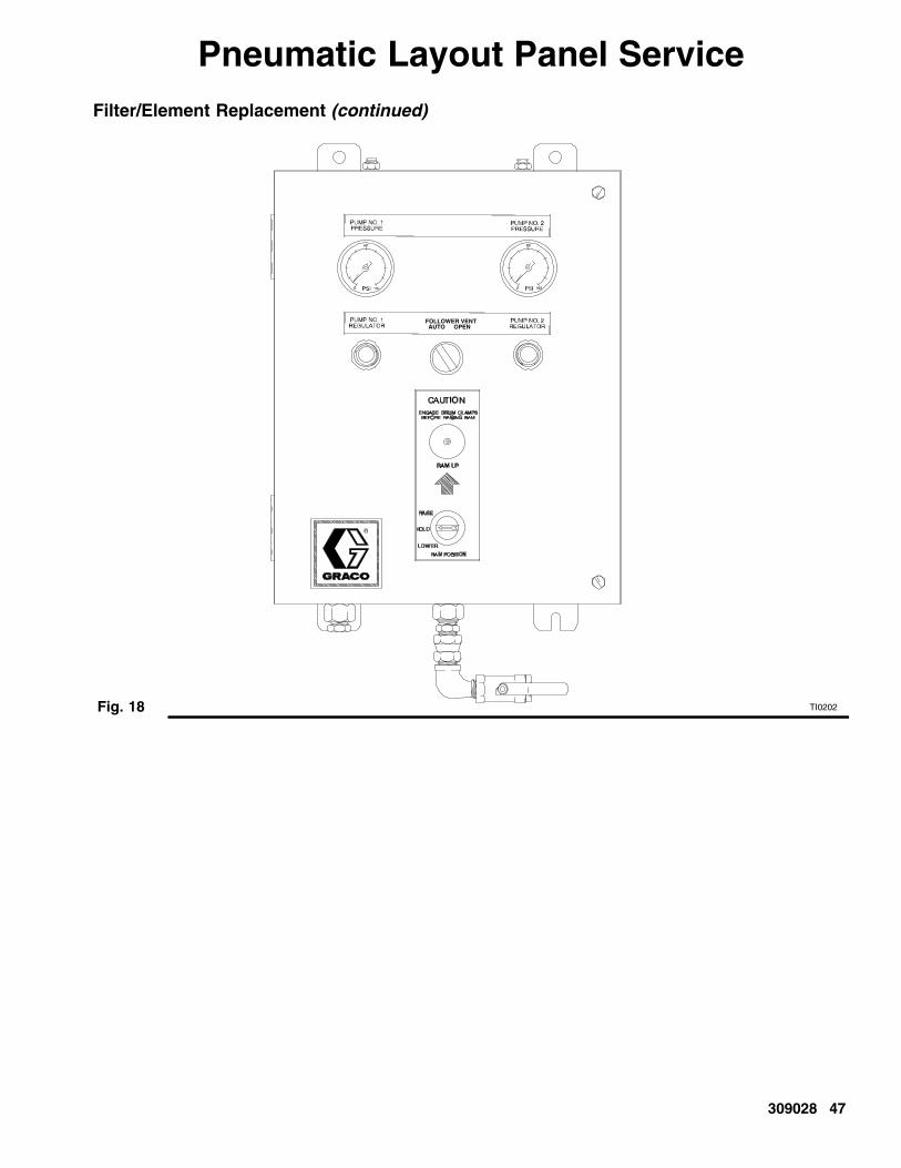
309028 47
Pneumatic Layout Panel ServiceFilter/Element Replacement (continued)
Fig. 18 TI0202
FOLLOWER VENTAUTO OPEN

48 309028
Ram Assembly ServicePiston Rod Seal Service (Fig. 19)
WARNINGTo reduce the risk of serious injury whenever youare instructed to relieve pressure, always follow thePressure Relief Procedure on page 31.
1. Relieve the air pressure.
2. Remove the four nuts and lockwashers holding thetie bar to the rods. Remove the tie bar.
3. Remove the guide sleeve retaining ring by grippingthe ring tab with a pair of pliers and rotating thering out of its groove.
4. Remove the guide sleeve by sliding it off of therod. Four 1/4 in.–20 holes are provided to easeremoval of the guide sleeve.
WARNINGDo not use pressurized air to remove the guidesleeve or piston. Failure to follow this instructionmay result in personal injury.
5. Inspect the parts for wear or damage. Replace asnecessary.
6. Install new O-rings and seal guard. Lubricate thepackings with O-ring lubricant.
7. Slide the guide sleeve onto the rod and push it intothe cylinder. Replace the retaining ring by feedingit around the guide sleeve groove.
8. Reinstall the tie bar using the nuts and lockwash-ers. Torque to 40 ft–lb (54 N�m).
7056A
Fig. 19
Ring, Seal Guard
Sleeve
Ring
O-ring
O-ring
Refer to Repair Kit 918110.

309028 49
Ram Assembly ServiceRam Piston Service (Fig. 20)
WARNINGTo reduce the risk of serious injury, whenever youare instructed to relieve pressure, always follow thePressure Relief Procedure on page 31.
1. Relieve the air pressure.
2. Remove the tie bar as explained under PistonRod Seal Service.
3. Remove the guide sleeve and slide it off of thepiston rod.
WARNINGDo not use pressurized air to remove the guidesleeve or piston. Failure to follow this instructionmay result in personal injury.
4. Carefully pull the piston rod straight up out of thecylinder. If the rod is cocked to one side, the pistonor inside surfaces of the cylinder could be dam-aged.
5. Carefully lay the piston and rod down so the rodwill not be damaged or bent. Remove the lowerpiston retaining ring. Slide the piston off the pistonrod.
6. Install new O-ring seals on the piston rod and thepiston. Lubricate the piston and seals. Reinstall thepiston and retaining ring.
7. Carefully insert the piston into the cylinder andpush the rod straight down into the cylinder. Add3 ounces of lubricant to each cylinder after insert-ing the piston.
8. Slide the guide sleeve onto the piston rod. Rein-stall the retaining ring and tie bar, as explainedunder Piston Rod Seal Service.
7056A
Fig. 20
O-ring
Band
PistonRing
O-ring
Ring

50 309028
Ram Assembly ServiceThe ram assembly service procedures include:
� Low/Empty limit switch replacement
� Ball seat applicator repair procedure
� Servicing the pumps
Low/Empty Limit Switch Replacement
To replace the lower limit switch, do the following:
1. Perform the System Shutdown procedure pro-vided by the integrator at the applicable supply unit(LH or RH).
WARNINGELECTROCUTION HAZARDInstalling and servicing this equipmentrequires access to parts which couldcause an electric shock or other serious
injury. Have only qualified electricians access thecontrol assembly.
2. Shut off power to the junction box panel.
NOTE: When raising and lowering the follower plate,be sure that the unit is unobstructed overhead to avoidinterference with other objects.
NOTE: The first limit switch closes when the followerplate reaches the preset low limit level in the drum.The second limit switch closes when the follower platereaches the preset empty level in the drum. Both limitswitches provide inputs to the PLC interface.
Switch Removal
3. Between the two limit switches (305), locate thefaulty switch. See Fig. 21.
4. Disconnect the wiring (301) for the limit switch atits power source. For reference, use the wiringdiagram shown in Fig. 21.
5. Mark the surface on the ram limit bracket using afelt-tipped pen to ensure that the new lower limitswitch is installed in the same spot.
6. Measure the distance from the mounting bracket(306) to the outer diameter of the limit switch rollerto ensure that the new roller is installed in thesame position.
7. Remove three cap screws (302), the lock washers(303), the plain washers (304), and the limit switch(305) from the limit bracket (306). See Fig. 21.
Fig. 21
301
302, 303, 304
305
306
307, 308309, 310
311
TI0200
Pin 1
Pin 3
Pin 2
Pin 5
Pin 4

309028 51
Ram Assembly ServiceLow/Empty Limit Switch Replacement(continued)
Switch Replacement
8. Install the new limit switch (305) on the limit brack-et (306) using the three cap screws (302), lockwashers (303), and plain washers (304). See Fig.21.
9. Reconnect the wiring (301) for the limit switch atits power source. For reference, use the wiringdiagram shown in Fig. 21.
10. Make sure that the limit switch roller is positionedin the same location per the measurement in step6. See Fig. 21.
11. Reinstall the cover on the junction box panel.
12. Reapply power to the junction box panel.
13. Perform the Daily System Startup procedureprovided by the integrator at the applicable supplyunit (LH or RH).
14. Verify that the limit switch operates correctly.
15. Return the system to current readiness condition.
Depressurization Valve (Ball SeatApplicator) Repair Procedure
Refer to instruction manual 310550 for the ball seatapplicator (918537) service procedures and partsinformation.
Servicing the Pumps
When the pumps and air motors require service, referto the applicable instruction manual, listed below, fordetailed information.
Form Description P/N
308147 Carbon Steel Dura-Flo�Pump 1800 with Premier�Air Motor
237555
308148 Stainless Steel Dura-Flo�Pump 1800 with Premier�Air Motor
241957
308213 Premier� Air Motor 222800

52 309028
Ram Assembly ServiceReplacing Wipers (Fig. 22)
1. Perform the System Shutdown procedure pro-vided by the integrator.
2. To replace worn or damaged wipers (412), raisethe follower plate up out of the drum. Remove thedrum from the base. Wipe the fluid off the followerplate. Refer to the Drum Changing procedure onpage 32.
3. Separate the wiper joint (A) and bend back thestrapping (413) covering the clamp setscrew (415).See Detail A of Fig. 22. Loosen the setscrew, pullthe end of the strapping through the clamp (414)and remove the wiper.
4. Slide the strapping (413) through the new wiper(412). Slide the clamp (414) onto the new strap-ping and bend the strapping back approximately 3in. (76 mm). Insert the strapping through the clampa second time. See Detail B of Fig. 22.
5. Install the wipers on the follower plate. Position thewipers so that their joints (A) are 180� apart.
NOTE: You will need the special banding tool (C)shown in Detail C of Fig. 22 to tighten the strapping.Order Part No. 168092 Banding Tool.
6. Grip the strapping (413) with the tool (C) asshown. With your thumb on the gripper lever (E),turn the tool handle (F) clockwise to apply tension.
NOTE: Be careful not to pull the cutting handle (D)until you are ready to cut the strapping in step 8.
7. Continue turning the tool handle until you see thestrapping stop moving through the clamp (414).Stop turning the handle.
8. Tighten the setscrew (B) with a wrench (G). Pullthe cutting handle (D) to cut. Remove the tool (C).Bend the strapping back over the clamp (414).
9. Pound the wiper all the way around with a rubbermallet until the joints (A) are butted tightly together.
10. Return the system to current readiness condition.Refer to the Drum Changing procedure on page32.
05712
Fig. 22
1
3
2
0294602949
Detail A Detail B
Detail C
Slide the clamp onto the strapping and bend the strapping backapproximately 3 in. (76 mm).
Turn clockwise to apply tension.
Cut the strapping and bend it back over the clamp.
E
F413
D
C
G
415
414
412 414 413A
413415
414412
1
2
3H

309028 53
Pump Assembly ServicePump Removal(Refer to System Parts Diagram; page 54.)
WARNINGTo reduce the risk of serious injury, whenever youare instructed to relieve pressure, always follow thePressure Relief Procedure on page 31.
1. Relieve the air pressure from the air motors andram assembly to be serviced.
2. Move the RAM POSITION switch to HOLD.
3. Close the pump outlet ball valves and relieve thefluid pressure from the pumps at the pump bleedvalve on the ram assembly to be serviced.
4. Using an overhead lifting device, attach and se-cure a chain capable of lifting the weight of thepump assembly to the eye at the top of the airmotor.
NOTE: For effective pump removal, the lifting pointmust be directly above the pump and capable ofmoving sideways. The lifting action should be the“chain fall” type that allows a slow upward and down-ward movement.
NOTE: Check the Technical Data page in the separatepump manual to find the weight of the pump beingserviced. For example, Graco Premier 45:1 SST Pump(222939) weighs 240 lb (109 kg) per Form 308148.
5. Detach the air hose from the air motor.
6. Detach the fluid supply hose at the pump outlet.
NOTE: When loosening the pump and the air motorfasteners in steps and below, ensure the chain slackis taken up to prevent the pump assembly from falling.
7. On the follower plate adapter, loosen and rotate orremove four lugs and hex bolts holding the flangeof the pump lower .
8. On the underside of the air motor, remove thebolts securing the air motor to the motor supportbrackets. It may be necessary to move or removesome brackets for effective pump removal.
9. Detach any other connections to the pump as-sembly to ensure the pump is free of attachmentsbefore removal. Possible connections include:
� Air motor exhaust kit
� Pump proximity switch kit
� Pump grounding wire
NOTE: When lifting the pump in step below, ensurethe lifting chain does not damage the air controlsmounted at the top of the ram cross-members.
10. Using a “chain fall” style lifting device, slowly pullthe pump upward a few inches until the base of thepump clears the pump mounting adapter and theair motor clears the support brackets.
11. Pull the pump assembly out of the ram assemblyand guide the pump assembly downward to thefloor, placing the base of the pump on a woodsurface and taking care not to damage the sealarea of the pump inlet housing.
12. Remove the gasket and o-ring (items 32 and 33)from the pump adapter. They should be discardedand replaced when the pump is reinstalled.
13. Clean excess and hardened material from thepump adapter on the follower plate.
14. Ensure that material is not rising through the pumpadapter in the follower plate. If material is flowingupward, move the RAM POSITION switch toRAISE until the flow stops, then move the switchback to HOLD.
15. Move the pump assembly to a suitable work areaand repair the pump using the appropriate GracoInstruction Manual.
Pump Installation(Refer to System Parts Diagram; page 54.)
1. When the pump is serviced and tested and readyto be replaced in the Uni-Drum Ram, perform thesteps of the Pump Removal procedure in reverseorder.
2. It is recommended that the pump be tagged withthe type and date of repair and the name of thetechnician who performed the repair.
3. Before returning the reassembled pump to produc-tion use, it must be primed with material and airremoved from the material. Follow the PumpInstruction Form and the pump material bleedingprocedure from the Drum Changing Procedure onpage 32 .

54 309028
Parts246981, 248306, 249339, 253676, 258910, and 255666 45:1 Left Hand Supply Unit
246982, 248307, 249340, 253677, 258911, and 255665 45:1 Right Hand Supply Unit
249152, 249341, 234972, 258956, and 24H017 34:1 Left Hand Supply Unit
249153, 249342, 234973, 258957, and 24H016 34:1 Right Hand Supply Unit
67, 72 69 32
68697071
76
26662646
7
15
93, 94 97
27
2646
Detail F
97
116
107
84
See detail F
29 34 12 30 12 83 12 3019
202122
36
37
39, 40, 73
11
5069, 44, 22
23
45
42, 43
2618 1038
62, 6465 61 57, 58, 59
5655, 6354
10
77
99, 100101
98
14
35, 48
17
47
3
5, 9, 49
419, 41, 48, 49
80
3352
6
49, 31
13
38
16
60 28
117

309028 55
Parts246981, 248306, 249339, 253676, 258910, and 255666 45:1 Left Hand Supply Unit
246982, 248307, 249340, 253677, 258911, and 255665 45:1 Right Hand Supply Unit
249152, 349341, 234972, 258956, and 24H017 34:1 Left Hand Supply Unit
249153, 349342, 234973, 258957, and 24H016 34:1 Right Hand Supply Unit
ti4546a
90 92 91 63, 89
88
93
8103 104 32 108 102
109
8281
10 See detail C 10
11610
11073, 115
87
86
14, 73, 74
113
114
2419 20 53 25
96 95111112
Detail C
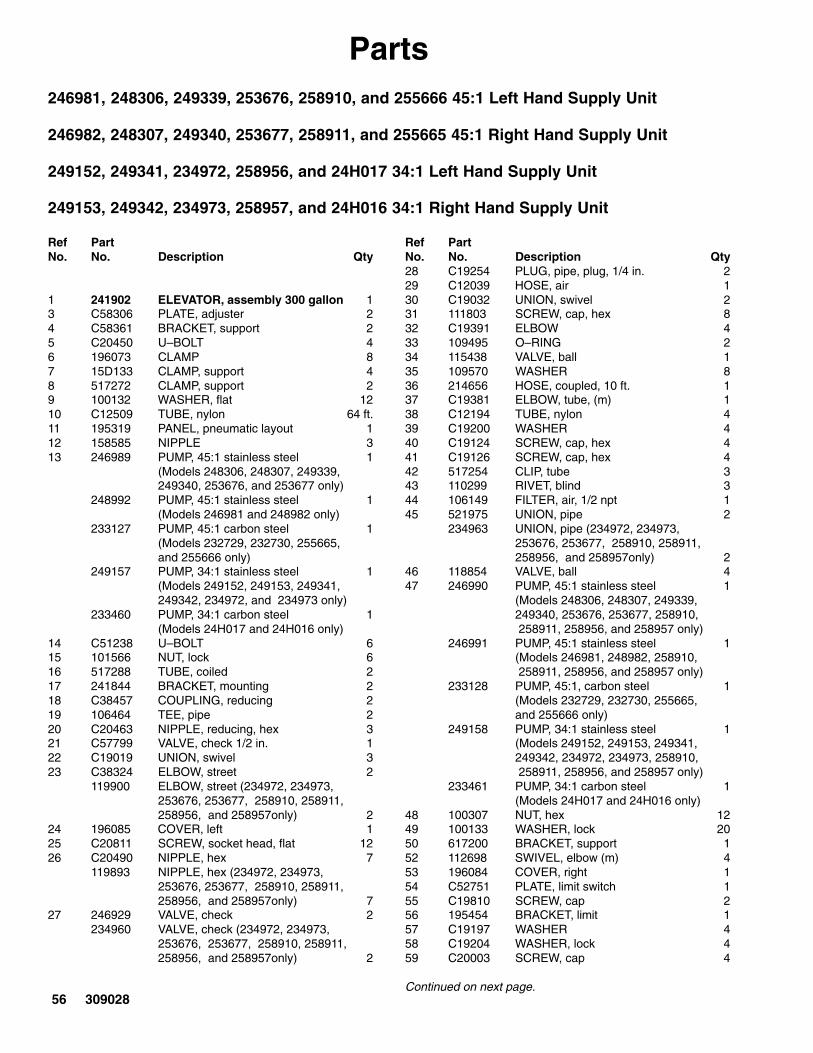
56 309028
Parts246981, 248306, 249339, 253676, 258910, and 255666 45:1 Left Hand Supply Unit
246982, 248307, 249340, 253677, 258911, and 255665 45:1 Right Hand Supply Unit
249152, 249341, 234972, 258956, and 24H017 34:1 Left Hand Supply Unit
249153, 249342, 234973, 258957, and 24H016 34:1 Right Hand Supply Unit
Ref PartNo. No. Description Qty
1 241902 ELEVATOR, assembly 300 gallon 13 C58306 PLATE, adjuster 24 C58361 BRACKET, support 25 C20450 U–BOLT 46 196073 CLAMP 87 15D133 CLAMP, support 48 517272 CLAMP, support 29 100132 WASHER, flat 1210 C12509 TUBE, nylon 64 ft.11 195319 PANEL, pneumatic layout 112 158585 NIPPLE 313 246989 PUMP, 45:1 stainless steel 1
(Models 248306, 248307, 249339, 249340, 253676, and 253677 only)
248992 PUMP, 45:1 stainless steel 1(Models 246981 and 248982 only)
233127 PUMP, 45:1 carbon steel 1(Models 232729, 232730, 255665,and 255666 only)
249157 PUMP, 34:1 stainless steel 1(Models 249152, 249153, 249341,249342, 234972, and 234973 only)
233460 PUMP, 34:1 carbon steel 1(Models 24H017 and 24H016 only)
14 C51238 U–BOLT 615 101566 NUT, lock 616 517288 TUBE, coiled 217 241844 BRACKET, mounting 218 C38457 COUPLING, reducing 219 106464 TEE, pipe 220 C20463 NIPPLE, reducing, hex 321 C57799 VALVE, check 1/2 in. 122 C19019 UNION, swivel 323 C38324 ELBOW, street 2
119900 ELBOW, street (234972, 234973, 253676, 253677, 258910, 258911,258956, and 258957only) 2
24 196085 COVER, left 125 C20811 SCREW, socket head, flat 1226 C20490 NIPPLE, hex 7
119893 NIPPLE, hex (234972, 234973,253676, 253677, 258910, 258911,258956, and 258957only) 7
27 246929 VALVE, check 2234960 VALVE, check (234972, 234973,
253676, 253677, 258910, 258911,258956, and 258957only) 2
Ref PartNo. No. Description Qty28 C19254 PLUG, pipe, plug, 1/4 in. 229 C12039 HOSE, air 130 C19032 UNION, swivel 231 111803 SCREW, cap, hex 832 C19391 ELBOW 433 109495 O–RING 234 115438 VALVE, ball 135 109570 WASHER 836 214656 HOSE, coupled, 10 ft. 137 C19381 ELBOW, tube, (m) 138 C12194 TUBE, nylon 439 C19200 WASHER 440 C19124 SCREW, cap, hex 441 C19126 SCREW, cap, hex 442 517254 CLIP, tube 343 110299 RIVET, blind 344 106149 FILTER, air, 1/2 npt 145 521975 UNION, pipe 2
234963 UNION, pipe (234972, 234973,253676, 253677, 258910, 258911,258956, and 258957only) 2
46 118854 VALVE, ball 447 246990 PUMP, 45:1 stainless steel 1
(Models 248306, 248307, 249339,249340, 253676, 253677, 258910, 258911, 258956, and 258957 only)
246991 PUMP, 45:1 stainless steel 1(Models 246981, 248982, 258910, 258911, 258956, and 258957 only)
233128 PUMP, 45:1, carbon steel 1(Models 232729, 232730, 255665,and 255666 only)
249158 PUMP, 34:1 stainless steel 1(Models 249152, 249153, 249341,249342, 234972, 234973, 258910, 258911, 258956, and 258957 only)
233461 PUMP, 34:1 carbon steel 1(Models 24H017 and 24H016 only)
48 100307 NUT, hex 1249 100133 WASHER, lock 2050 617200 BRACKET, support 152 112698 SWIVEL, elbow (m) 453 196084 COVER, right 154 C52751 PLATE, limit switch 155 C19810 SCREW, cap 256 195454 BRACKET, limit 157 C19197 WASHER 458 C19204 WASHER, lock 459 C20003 SCREW, cap 4
Continued on next page.

309028 57
Parts (Continued from previous page)
246981, 248306, 249339, 253676, 258910, and 255666 45:1 Left Hand Supply Unit
246982, 248307, 249340, 253677, 258911, and 255665 45:1 Right Hand Supply Unit
249152, 249341, 234972, 258956, and 24H017 34:1 Left Hand Supply Unit
249153, 249342, 234973, 258957, and 24H016 34:1 Right Hand Supply Unit
Ref PartNo. No. Description Qty
60 C07431 CONNECTOR, sealed 261 104227 NUT, lock 262 C19138 SCREW, cap, hex 263 100016 WASHER, lock 664 100018 WASHER, lock spring 265 C07560 SWITCH, limit, with arm 266 15D140 MANIFOLD, three–way 1
15G091 MANIFOLD, three–way (234972, 234973, 258910, 258911, 258956, and 258957 only) 1
67 C19491 TEE, fitting, 1–1/4 npt(f) 1119901 TEE, fitting, 1–1/4 npt(f)
(234972, 234973, 258910, 258911, 258956, and 258957 only) 1
68 918537 APPLICATOR, ball seat, 1/2 in. 169 C20485 NIPPLE, hex 3
114373 NIPPLE, hex (234972, 234973,253676, 253677, 258910, 258911, 258956, and 258957 only) 3
70 158566 COUPLING, hex pipe 115G092 COUPLING, hex pipe
(234972, 234973 only) 171 234558 HOSE, coupled 1
234962 HOSE, coupled (234972, 234973,253676, and 253677 only) 1
72 C19660 FITTING, 1–1/4 x 1/2 in. 1119896 FITTING, 1–1/4 x 1/2 in.
(234972, 234973 only) 173 C19213 WASHER, lock 1074 C19185 NUT, jam hex 476 234428 HOSE, coupled 2
234961 HOSE, coupled (234972, 234973,253676, 253677, 258910, 258911,258956, and 258957 only) 2
77 234255 KIT, accessory, PLC interface 1(Models 246981, 246982, 248306, 248307, 249152, 249153, 234972,234973, 253676, and 253677 only)
249343 KIT, accessory, PLC interface 1(Models 249339, 249340, 249341,249342,258910, 258911, 258956, and 258957 only)
79 114158 ADAPTER, fitting 1
Ref PartNo. No. Description Qty
80 195356 KIT, accessory 181 158555 NIPPLE, reducing 282 113332 VALVE, ball 290 617338 BRACKET, mounting 291 517455 SWITCH 292 C56572 CABLE 293 196510 COUPLING, housing 294 119417 SCREW 295 516102 CLAMP, pipe 196 114508 NIPPLE 197 233041 PLATE, ram, Neoprene 498 617180 ROD, connecting 899 101535 NUT 8100 101533 WASHER, spring lock 1101 617204 CARRIAGE, weldment, 300 gallon 2102 100549 ELBOW, street 2103 C20461 NIPPLE, reducing, hex 2104 515147 REGULATOR, air, 1/2p 2107 115419 ADAPTER, fitting 2108 214849 LUBRICATOR 2109 517290 HOSE 2110 C19438 ELBOW, fitting, 90� 2111 C19630 NIPPLE, fitting, 1npt 1112 114112 CONNECTOR, fitting (f) 2113 113093 CONNECTOR, pipe 2114 C20378 BRANCH, fitting 2115 100469 SCREW, cap, hex 2116 502526 VALVE, air three–way 2117 246994 VALVE, pressure, bleed 1118 120163 KIT, safety, lockout (not shown)
(Models 234972, 234973, 253676, and 253677 only) 1

58 309028
Parts232729, 45:1 Left Hand Supply Unit, with carbon steel pump232839, 45:1 Left Hand Supply Unit, with stainless steel and ceramic pump232730, 45:1 Right Hand Supply Unit, with carbon steel pump (shown)232840, 45:1 Right Hand Supply Unit, with stainless steel and ceramic pump246921, 45:1 Right Hand Supply Unit, with stainless steel pump246922, 45:1 Left Hand Supply Unit, with stainless steel pump255666, 45:1 Left Hand Supply Unit, with carbon steel pump255665, 45:1 Right Hand Supply Unit, with carbon steel pump
19
2021
22
36
12
16
2
1
35, 17, 14
13
3
4
5, 9, 40, 11
6, 31, 40
32, 33
15
8, 9, 11, 40
7
2934
12
30
39
TI0195
TI0198
TI0141
47
5224, 25
49, 50
4126
462645
44
43
42
53, 25
TI0141c
10

309028 59
System Parts232729, 45:1 Left Hand Supply Unit, with carbon steel pump232839, 45:1 Left Hand Supply Unit, with stainless steel and ceramic pump232730, 45:1 Right Hand Supply Unit, with carbon steel pump (shown)232840, 45:1 Right Hand Supply Unit, with stainless steel and ceramic pump246921, 45:1 Right Hand Supply Unit, with stainless steel pump246922, 45:1 Left Hand Supply Unit, with stainless steel pump255666, 45:1 Left Hand Supply Unit, with carbon steel pump255665, 45:1 Right Hand Supply Unit, with carbon steel pump
Ref PartNo. No. Description Qty
Ref PartNo. No. Description Qty
1 241902 ELEVATOR, assembly 300 gallon;see page 73 1
2 241891 FOLLOWER PLATE ASSY;243510 see page 64 1
3 C58360 PLATE, adjuster, Uni-Drum 24 C58361 BRACKET, pump support 25 C20450 U-BOLT 46 196073 CLAMP 87 241837 KIT, accessory, pneumatic;
see page 61 18 C19126 SCREW, cap hex head 49 100132 WASHER, flat 1610 101566 NUT, lock 611 100307 NUT, hex; 3/8-16 1212 158585 NIPPLE 213 233127 PUMP, 45:1; carbon steel;
used on Model 232729, 232730,255665, and 255666 only;see manual 308147 2
241957 PUMP, 45:1; stainless steel andceramic; used on Model 232839 only;see manual 308148 2
246923 PUMP, 45:1; stainless steel;used on Model 246921 only;see manual 308148 2
14 C51238 U-BOLT; 6 in. tube x 1/2-13un 415 241838 KIT, accessory, PLC interface;
see page 69 116 241840 KIT, accessory, depressurization;
see page 60 117 241844 BRACKET, mounting 219 106464 TEE, pipe; 1 in. npt 120 C20463 NIPPLE, fitting hex reducing; 1 in. 121 C57799 VALVE, check; 1/2 npt (fbe) 1
22 C19019 FITTING, union, swivel 224 196085 COVER, left 125 C20811 SCREW, socket, flat head 1226 C20490 FITTING, nipple, hex 229 C12039 HOSE, air; 1 in. ID 130 C19032 SWIVEL, adapter, union 131 111803 SCREW, cap, hex head 832 184086 GASKET 233 109495 O-RING 134 115438 VALVE, ball; 1 in. locking 135 109570 WASHER, plain 836 214656 HOSE; 1/2 in ID; 10 ft long 239 243488 KIT, accessory; see page 63 240 100133 LOCKWASHER, spring; 3/8 in. 2041 C38457 COUPLING, reducing 242 521850 VALVE, check 243 C38324 ELBOW, street 244 233058 HOSE, coupled 245 521975 UNION, pipe 246 118854 VALVE, ball 247 233128 PUMP, 45:1; carbon steel;
used on model 232729, 232730,255665, and 255666 only; ;see manual 308147 1
243689 PUMP, 45:1; stainless steel andceramic; used on model 232839 only;see manual 308148 1
246924 PUMP, 45:1; stainless steel;used on model 246922 only;see manual 308148 1
49 101535 NUT, hex; 7/8 in. 450 101533 LOCKWASHER, spring; 7/8 in. 452 112698 ELBOW, swivel; 1/8 npt 453 196084 COVER, right 1

60 309028
System Parts
Part No. 241840, Depressurization Kit
Ref PartNo. No. Description Qty
Ref PartNo. No. Description Qty
16a C19254 PLUG, pipe 216c 918537 APPLICATOR, ball seat;
see 310550 for parts 116d C20490 NIPPLE 116e C19660 BUSHING 116f C19491 TEE 1
16g C19391 ELBOW, swivel 216h 215241 HOSE 116j 156172 UNION 216k 157129 NIPPLE 116m C20485 NIPPLE 216n C19685 BUSHING 1
16a
16c16d
16e, 16f, 16m16g
16m
16j, 16n16h
16j, 16k
TI0195

309028 61
System Parts
Part No. 241837, Pneumatic Accessory Kit
Ref PartNo. No. Description Qty
Ref PartNo. No. Description Qty
7a C12509 TUBE; nylon 248 in.7b C12509 TUBE; nylon 200 in.7c C12509 TUBE; nylon 23 in.7d C12509 TUBE; nylon 31 in.7e 517272 CLAMP, support 27f C20378 FITTING, Y-branch 27g 517288 TUBE; 1/4 in. 27h 195319 PANEL, pneumatic layout;
see page 66 17j C19381 CONNECTOR; 1/2 npt x 1/2 in. tube 17k C12194 TUBE; 1/2 in. 8 in.7m C12509 TUBE; nylon 120 in.
7n C12194 TUBE; 1/2 in. 40 in.7p C19399 CONNECTOR; 1/2 npt x 1/2 in. tube 17r C19200 WASHER, plain 47s C19124 SCREW, cap, hex hd 47t C19213 WASHER, lock 47u 517254 CLIP, tube 37v 110299 RIVET 37w 106149 FILTER, air; 1/2 npt 17x C20485 FITTING; 1/2 npt 17y C19019 UNION, swivel 17z 617200 SUPPORT, bracket 1
7a 7b
7c7d
7e 7f
7g
7h7j
7k
7m
7n
7p
7r, 7s, 7t
7u, 7v
7w, 7x, 7y
7z
TI0201

62 309028
Parts
Part No. 241839, Low/Empty Limit Kit (For Uni-Drum Use)
Ref PartNo. No. Description Qty
Ref PartNo. No. Description Qty
301 C07431 CONNECTOR, sealed 2302 C20003 CAPSCREW, socket head 4303 C19204 WASHER, lock #10 bolt 4304 C19197 WASHER, plain 4305 C07560 SWITCH, limit 2306 195454 BRACKET, limit, low-level, Uni-Drum 1
307 C19810 CAPSCREW, socket head 2308 100016 WASHER, spring lock; 1/4 in. 2309 C19138 SCREW, cap, hex head 2310 100018 LOCKWASHER, spring; 1/2 in. 2311 C52751 PLATE, limit switch 1312 104227 NUT, lock 2
301
302, 303, 304
305
306
307, 308309, 310
311
TI0200b
312

309028 63
Parts
Part No. 243488 Proximity Switch Accessory Kit
Ref PartNo. No. Description Qty
Ref PartNo. No. Description Qty
601 617337 COLLAR, clamp 2602 100016 WASHER, lock; 1/4 in. 2603 C19800 SCREW, socket hd; 1/4–20 x 1/2 in. 2604 617338 BRACKET, proximity switch mounting 1
605 517455 SWITCH, proximity; 18 mm 1606 C56572 CABLE, proximity; 2 m long 1611 196510 HOUSING, coupling nut 1612 C19363 SCREW, cup point set; 1/4–20 x 1/2 in. 1
TI1479A
TI1479A
601
602, 603
604
605
606
612
611

64 309028
Parts
Part Nos. 241891 and 243510, Follower Plate Assembly
642
641
640631
636, 637
638
633, 639
635
603 634 633 632 631 604 603
612,613614
615
616
610
611
605
609644
627
626
624625623
622621
620
643
TI0206
TI0138
TI0204 TI0139
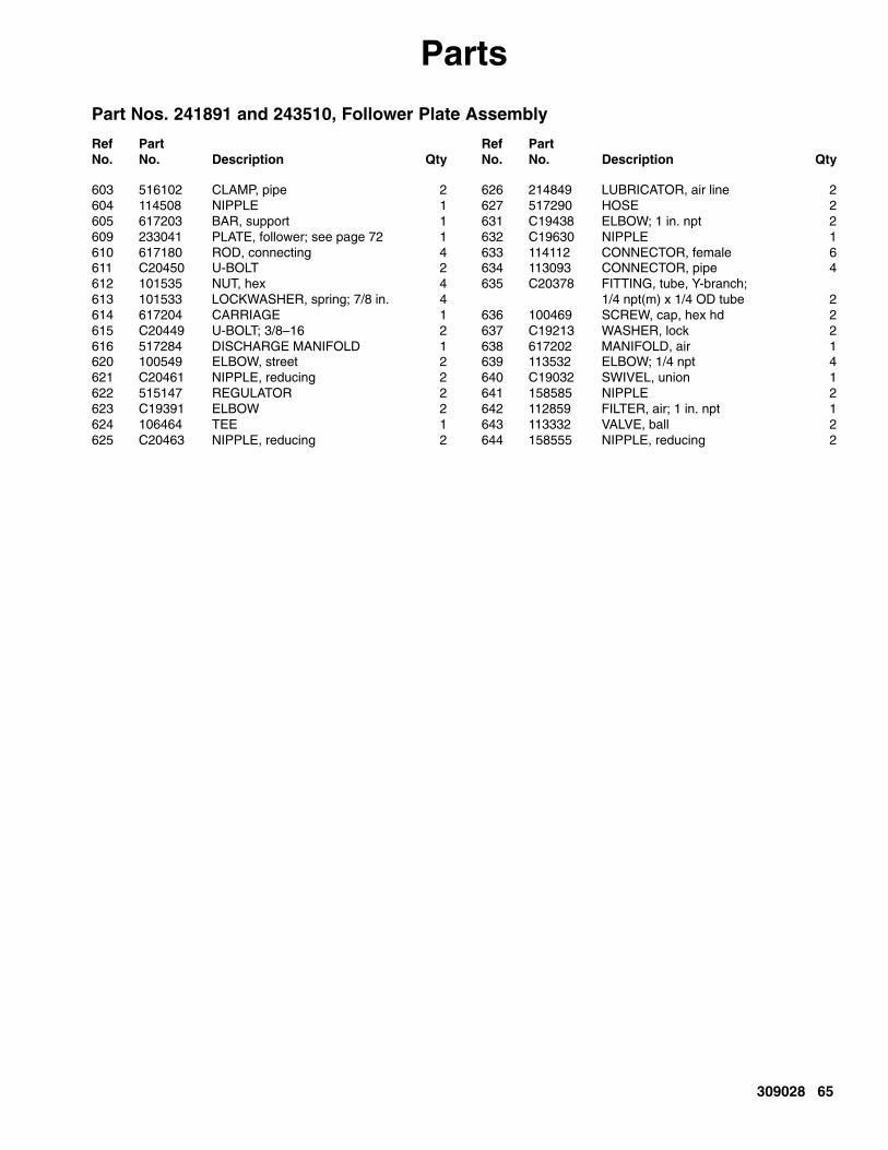
309028 65
Parts
Part Nos. 241891 and 243510, Follower Plate Assembly
Ref PartNo. No. Description Qty
Ref PartNo. No. Description Qty
603 516102 CLAMP, pipe 2604 114508 NIPPLE 1605 617203 BAR, support 1609 233041 PLATE, follower; see page 72 1610 617180 ROD, connecting 4611 C20450 U-BOLT 2612 101535 NUT, hex 4613 101533 LOCKWASHER, spring; 7/8 in. 4614 617204 CARRIAGE 1615 C20449 U-BOLT; 3/8–16 2616 517284 DISCHARGE MANIFOLD 1620 100549 ELBOW, street 2621 C20461 NIPPLE, reducing 2622 515147 REGULATOR 2623 C19391 ELBOW 2624 106464 TEE 1625 C20463 NIPPLE, reducing 2
626 214849 LUBRICATOR, air line 2627 517290 HOSE 2631 C19438 ELBOW; 1 in. npt 2632 C19630 NIPPLE 1633 114112 CONNECTOR, female 6634 113093 CONNECTOR, pipe 4635 C20378 FITTING, tube, Y-branch;
1/4 npt(m) x 1/4 OD tube 2636 100469 SCREW, cap, hex hd 2637 C19213 WASHER, lock 2638 617202 MANIFOLD, air 1639 113532 ELBOW; 1/4 npt 4640 C19032 SWIVEL, union 1641 158585 NIPPLE 2642 112859 FILTER, air; 1 in. npt 1643 113332 VALVE, ball 2644 158555 NIPPLE, reducing 2

66 309028
Parts
195319, PLC Pneumatic Layout Panel
129, 130
101
103
115
110
106
117
110
115
119 107
133133
152 TI0202b TI0143b
129
134
129
143
105
129, 130
134
FOLLOWER VENTAUTO OPEN

309028 67
Parts
195319, PLC Pneumatic Layout Panel
Ref No. Graco Part No. Manufacturer Part No. Description Qty
101 A–20 HOFFMAN ENCLOSURE 1102 A–20P16 HOFFMAN BACK PANEL 1103 195321 1104 6522–53–32 CAMOZZI SWL M ELB 1105 BV–4 UCI MUFFLER 1106 NVM151–N01–35 SMC 1107 SEL–4–RED UCI BALL VALVE 1108 6540–08–00 CAMOZZI UNION T 3109 RO5X51P WATTS PANEL NUT 2110
R35–01C WATTS QUBE REGULATOR 2
111 RO5X51P WATTS PANEL NUT 2112a 6532B–241RA MAC 1112b PR65C–35HA MAC 1113 2543–04–04 CAMOZZI COUPLING 2114 R35–02A WATTS QUBE REGULATOR 1115 CDS–1P–010–B DYNAMIC FLUID GAUGE 2116 6800–04–08 CAMOZZI REDUCER 3117 517313 1118 6540–53–00 CAMOZZI UNION T 3119 PC125B–8 POLLYCON MALE ELBOW 1120 PCU–156F–2 POLLYCON TUBING 50 ft121 PCU–500F–2 POLLYCON TUBING 5 ft122 PCU–250F–2BLK POLLYCON TUBING 20 ft123 P6520–53–02 CAMOZZI SWL M–ELB 9124 P6520–04–04 CAMOZZI SWLM–ELB 5125 6510–08–08 CAMOZZI MALE CON 2126 P6520–08–08 CAMOZZI SWT M–ELB 4127 P6430–04–02 CAMOZZI M–BR T–SWL 1128 P6510–04–04 CAMOZZI MALE CONN 1129 6590–04–00 CAMOZZI BULKHEAD 5130 6800–53–04 CAMOZZI REDUCER 2131 6560–53–00 CAMOZZI UNION Y 2132 C19254 2133 PC68BH–8 POLLYCON BULKHEAD CON 3134 6590–08–00 CAMOZZI BULKHEAD 2135 6580–53–00 CAMOZZI UNION 1136 6520–04–02 CAMOZZI SWL M–ELB 3137 P6520–53–04 CAMOZZI SWL M–ELB 2138 6950–08–00 CAMOZZI DBL UNION 1139 PCSCV–6 POLLYCON CHECK VALVE 1140 PC42G–64 POLLYCON REDUCER 2141 6540–04–00 CAMOZZI UNION T 3142 115826 1143 168491 1145 81–540–001 CROUZET ELEMENT 1152 PC121B–8 POLLYCON (NOTE: DRILL 0.125 IN. HOLE IN CENTER OF PLUG) 1153 SAD–1501–0–30 UCI GAUGE 1154 115793 2155 SEL–301–2 PNEUMADYNE 2 POSITION SELECTOR 1156 AOT PNEUMADYNE MOUNT 1157 AO–30–4 PNEUMADYNE VALVE 1

68 309028
Parts
195319, PLC Pneumatic Layout Panel
DV8
R3
160
124
154
132
124
123
101 115 137
125
103127
155156157
123
110
136
117
115 137
110
123
152
141
133 108
114
SeeDetailsBelow
126
129
112
9327c
123
TI0142b
113 113
104
118
106
131
130141
130
142
153128116125138
118
139
126
139
140
141
118
135
145

309028 69
Parts
241838 and 249343, PLC Interface Accessory Kit
Ref PartNo. No. Description Qty
Ref PartNo. No. Description Qty
201 195330 PLATE, mounting 1202 C55568 SWITCH, pressure; 1/4 in. npt 1
(241838 only)119776 SWITCH, pressure; 1/4 in. npt 1
(249343 only)203 115440 VALVE, assembly 1
(241838 only)119777 VALVE, assembly 1
(249343 only)204 597151 ELBOW, male 3205 111714 SCREW, S.H.C.; CS PL #4-40x 5/8 4206 103739 WASHER, lock; CS PL #4 4207 596936 SCREW, S.H.C.; 1/4–20 x 1.5 2209 100016 WASHER, lock; CS PL 1/4 2210 517449 MUFFLER 2211 C07434 CORD, 5–pin; 6 ft long 1212 C19407 FITTING, tube; 1/4T x 1/8P 2213 103219 PLUG, pipe; 1/8 npt 1
214 C19391 ELBOW, 90 degree, tube; 1/4P x 1/4T 1215 C19264 PLUG, pipe; 1/4 npt 2216 C20536 CABLE, 2 cond. 96 in.217 195320 PANEL, junction box; see page 70 1218 C51238 V-BOLT; 6 in. x 3/8-16 (not shown) 2219 C19185 JAM NUT (not shown) 4220 C19213 WASHER, lock; 3/8 (not shown) 4221 502526 VALVE, air 2222 501014 ACTUATOR, air 2223 104172 FITTING, tube 4224 115419 FITTING, adapter 2225 195356 KIT, accessory 1226 241839 KIT, low/empty limit; 1227 C07435 CORD, 5–pin; 12 ft long 3228 114158 FITTING, adapter, Y 1229 C19047 SCREW; 10-32 X 0.38 4230 C12509 TUBE; 1/4 in.; nylon 144 in.
229
217
201
202, 207, 209
211
214
212
210204 213
205, 206
215
203
230
228
222
223223
221
224
227
225
227 216230
230
230
226
A
A
B
B
TI0196

70 309028
Parts
Part No. 195320 and 119773, Junction Box Panel
70
80, 90, 100, 120 270 260, 280 110
190, 240200
30, 40
20
10
TI0205b
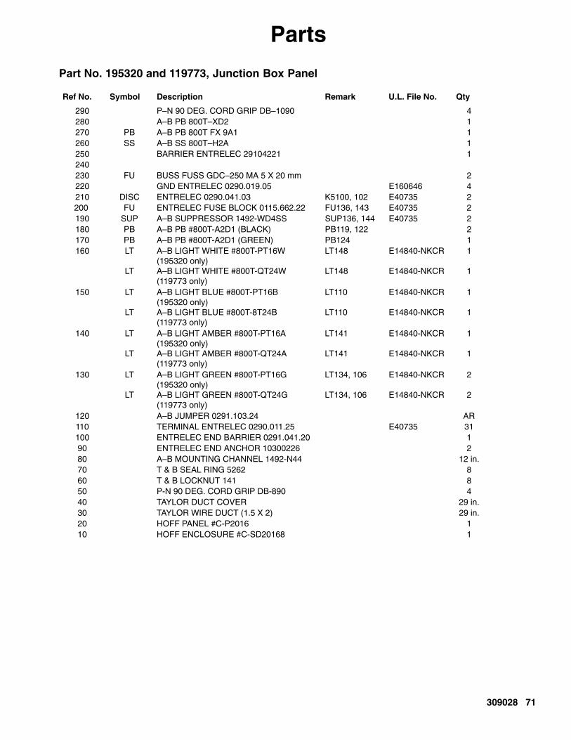
309028 71
Parts
Part No. 195320 and 119773, Junction Box Panel
Ref No. Symbol Description Remark U.L. File No. Qty
290 P–N 90 DEG. CORD GRIP DB–1090 4280 A–B PB 800T–XD2 1270 PB A–B PB 800T FX 9A1 1260 SS A–B SS 800T–H2A 1250 BARRIER ENTRELEC 29104221 1240230 FU BUSS FUSS GDC–250 MA 5 X 20 mm 2220 GND ENTRELEC 0290.019.05 E160646 4210 DISC ENTRELEC 0290.041.03 K5100, 102 E40735 2200 FU ENTRELEC FUSE BLOCK 0115.662.22 FU136, 143 E40735 2190 SUP A–B SUPPRESSOR 1492-WD4SS SUP136, 144 E40735 2180 PB A–B PB #800T-A2D1 (BLACK) PB119, 122 2170 PB A–B PB #800T-A2D1 (GREEN) PB124 1160 LT
LT
A–B LIGHT WHITE #800T-PT16W(195320 only)A–B LIGHT WHITE #800T-QT24W(119773 only)
LT148
LT148
E14840-NKCR
E14840-NKCR
1
1
150 LT
LT
A–B LIGHT BLUE #800T-PT16B(195320 only)A–B LIGHT BLUE #800T-8T24B(119773 only)
LT110
LT110
E14840-NKCR
E14840-NKCR
1
1
140 LT
LT
A–B LIGHT AMBER #800T-PT16A(195320 only)A–B LIGHT AMBER #800T-QT24A(119773 only)
LT141
LT141
E14840-NKCR
E14840-NKCR
1
1
130 LT
LT
A–B LIGHT GREEN #800T-PT16G(195320 only)A–B LIGHT GREEN #800T-QT24G(119773 only)
LT134, 106
LT134, 106
E14840-NKCR
E14840-NKCR
2
2
120 A–B JUMPER 0291.103.24 AR110 TERMINAL ENTRELEC 0290.011.25 E40735 31100 ENTRELEC END BARRIER 0291.041.20 190 ENTRELEC END ANCHOR 10300226 280 A–B MOUNTING CHANNEL 1492-N44 12 in.70 T & B SEAL RING 5262 860 T & B LOCKNUT 141 850 P-N 90 DEG. CORD GRIP DB-890 440 TAYLOR DUCT COVER 29 in.30 TAYLOR WIRE DUCT (1.5 X 2) 29 in.20 HOFF PANEL #C-P2016 110 HOFF ENCLOSURE #C-SD20168 1

72 309028
Parts
Part No. 233041 Follower Plate
Ref PartNo. No. Description Qty
Ref PartNo. No. Description Qty
401 233040 PLATE, ram 1402* 115782 CYLINDER, air 2403* 196052 SPACER 8404* 196053 PLATE 2405 517286 PLUNGER 2406* 115783 BOLT, hex hd 2407* 196051 SPACER 2408* 100333 SCREW, cap, hex hd 8409* 100016 WASHER, lock; 1/4 in. 8410* 112245 O-RING 2411* 115784 SCREW, cap, socket hd 8412** 617195 WIPER 2413** 068104 STRAPPING; steel 288 in.
414** 101817 CLAMP, banding 2415** 115785 SCREW, set 2416 617230 GASKET 2417 196072 RING, adapter 2418 233044 PLUG, vent 2419 C19843 CAPSCREW 4420 106115 LOCKWASHER 4421 102726 PLUG, pipe 2422 196122 SHIELD 2423 114269 GROMMET 2*These items may be purchase separately or in Kit 234958**These items may be purchased separately or in Wiper Kit,
918241.
401
402*
403*
421
416
418
419, 420
411*
413
414
415
412
TI0144
423 422
417
410* 405*
408*
406*
409*
404*
407*
SEE DETAIL B
DETAIL B
SEE DETAIL A
DETAIL A

309028 73
Parts
Part No. 241902 Elevator Assembly
9586A
531532
501
502
505
509 510 511 505(Ref)
536, 537
516, 527, 528 529530
506507, 508
517
518
519520
539 (Ref)
521
522
523
524
525
526501 (Ref)
538 539

74 309028
Parts
Part No. 241902 Elevator Assembly
Ref PartNo. No. Description Qty
Ref PartNo. No. Description Qty
501 517269 DRAIN COCK 4502 C12194 TUBE; 1/2 in. 136 in.505 114129 CONNECTOR, male 8506 617206 FRAME, elevator 1507* C31001 WIPER, rod 4508 C03043 RING, snap 4509 C20808 SCREW, socket, flat-head 16510 617179 PAD, rest 4516 100321 NUT 6517 C03042 RING, lock 4518* 121306 O-RING 4519* 156593 O-RING 4520 C31000 SLEEVE 4521 617176 ROD, lift 4522 C20417 RING, retaining 8523 C03046 PISTON, elevator 4
524* C20280 O-RING 4525* C03047 GUIDE, band 4526* 158776 O-RING 4527 C19130 SCREW, cap, hex hd 6528 100018 WASHER, lock 6529 194968 CLAMP 2530 517281 PIN, spring 2531 C14022 LABEL, warning 2532 C14007 LABEL, warning 4536 100681 NUT, jam, hex 2537 517411 KNOB 2538 114111 CONNECTOR, male 1539 100361 PLUG, pipe 3* These items may be purchased separately or in
Repair Kit 918110
Recommended Spare Parts
Spare Parts for 45:1 and 34:1 Uni-Drum Supply Units
The customer should maintain an inventory of the spare parts (per unit) listed below.
CSTUnits
SSTUnits
Description Qty.
ÁÁÁÁÁÁ
222555ÁÁÁÁÁÁÁÁ
222845ÁÁÁÁÁÁÁÁÁÁÁÁÁÁÁÁÁÁ
PUMP KIT (45:1 models only)
ÁÁÁÁÁÁÁÁ
2
ÁÁÁÁÁÁÁÁÁ
222881ÁÁÁÁÁÁÁÁÁÁÁÁ
222875ÁÁÁÁÁÁÁÁÁÁÁÁÁÁÁÁÁÁÁÁÁÁÁÁÁÁÁ
PUMP KIT (34:1 models only)
ÁÁÁÁÁÁÁÁÁÁÁÁ
2
ÁÁÁÁÁÁ
222958ÁÁÁÁÁÁÁÁ
222958ÁÁÁÁÁÁÁÁÁÁÁÁÁÁÁÁÁÁ
PREMIER AIR MOTOR KITÁÁÁÁÁÁÁÁ
2
ÁÁÁ222959ÁÁÁÁ222959ÁÁÁÁÁÁÁÁÁAIR VALVE KIT ÁÁÁÁ2ÁÁÁÁÁÁ
222982ÁÁÁÁÁÁÁÁ
222982ÁÁÁÁÁÁÁÁÁÁÁÁÁÁÁÁÁÁ
DETENT KITÁÁÁÁÁÁÁÁ
2ÁÁÁÁÁÁ
222981ÁÁÁÁÁÁÁÁ
222981ÁÁÁÁÁÁÁÁÁÁÁÁÁÁÁÁÁÁ
TRIP ROD KIT ÁÁÁÁÁÁÁÁ
2ÁÁÁÁÁÁ
515147ÁÁÁÁÁÁÁÁ
515147ÁÁÁÁÁÁÁÁÁÁÁÁÁÁÁÁÁÁ
AIR REGULATOR ÁÁÁÁÁÁÁÁ
1
ÁÁÁÁÁÁ
918537ÁÁÁÁÁÁÁÁ
918538ÁÁÁÁÁÁÁÁÁÁÁÁÁÁÁÁÁÁ
RECIRCULATING VALVEKIT
ÁÁÁÁÁÁÁÁ
2
ÁÁÁÁÁÁ
115440ÁÁÁÁÁÁÁÁ
115440ÁÁÁÁÁÁÁÁÁÁÁÁÁÁÁÁÁÁ
VALVE, solenoid ÁÁÁÁÁÁÁÁ
1
ÁÁÁÁÁÁ
C55568ÁÁÁÁÁÁÁÁ
C55568ÁÁÁÁÁÁÁÁÁÁÁÁÁÁÁÁÁÁ
SWITCH, pressure ÁÁÁÁÁÁÁÁ
1
ÁÁÁC07560ÁÁÁÁC07560ÁÁÁÁÁÁÁÁÁSWITCH, limit ÁÁÁÁ1
CSTUnits
SSTUnits
Description Qty.
ÁÁÁÁÁÁÁÁ
102774ÁÁÁÁÁÁ
102774 ÁÁÁÁÁÁÁÁÁÁÁÁÁÁÁÁÁÁLUBRICATOR KIT ÁÁÁ
ÁÁÁ1
ÁÁÁÁÁÁÁÁ
517285ÁÁÁÁÁÁ
517285 ÁÁÁÁÁÁÁÁÁÁÁÁÁÁÁÁÁÁAIR CYLINDER ÁÁÁ
ÁÁÁ1
ÁÁÁÁC20247ÁÁÁC20247 ÁÁÁÁÁÁÁÁÁO-RING ÁÁÁ2ÁÁÁÁÁÁÁÁ
517286ÁÁÁÁÁÁ
517286 ÁÁÁÁÁÁÁÁÁÁÁÁÁÁÁÁÁÁPLUNGER ÁÁÁ
ÁÁÁ2
ÁÁÁÁÁÁÁÁ
C03039ÁÁÁÁÁÁ
C03039 ÁÁÁÁÁÁÁÁÁÁÁÁÁÁÁÁÁÁUNI-DRUM ELEVATOR KIT ÁÁÁ
ÁÁÁ2
ÁÁÁÁÁÁÁÁ
162440ÁÁÁÁÁÁ
162440 ÁÁÁÁÁÁÁÁÁÁÁÁÁÁÁÁÁÁBOWL SEAL ÁÁÁ
ÁÁÁ1
ÁÁÁÁ502526ÁÁÁ502526 ÁÁÁÁÁÁÁÁÁPILOT VALVE ÁÁÁ1ÁÁÁÁÁÁÁÁ
501014ÁÁÁÁÁÁ
501014 ÁÁÁÁÁÁÁÁÁÁÁÁÁÁÁÁÁÁACTUATOR ÁÁÁ
ÁÁÁ1
ÁÁÁÁÁÁÁÁ
918110ÁÁÁÁÁÁ
918110 ÁÁÁÁÁÁÁÁÁÁÁÁÁÁÁÁÁÁAIR CYLINDER KIT ÁÁÁ
ÁÁÁ1
ÁÁÁÁÁÁÁÁ
918241ÁÁÁÁÁÁ
918241 ÁÁÁÁÁÁÁÁÁÁÁÁÁÁÁÁÁÁWIPER KIT ÁÁÁ
ÁÁÁ1
ÁÁÁÁÁÁÁÁ
234958ÁÁÁÁÁÁ
234958 ÁÁÁÁÁÁÁÁÁÁÁÁÁÁÁÁÁÁ
FOLLOWER PLATE VENTVALVE KIT ÁÁÁ
ÁÁÁ
1
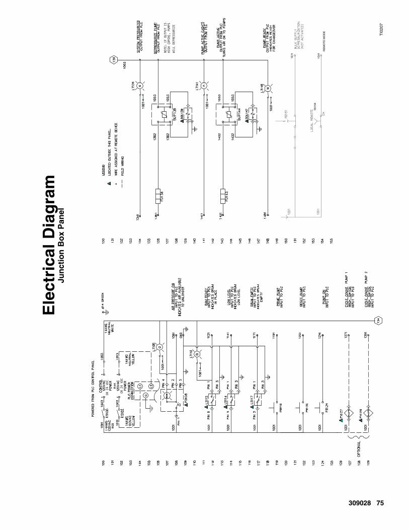
309028 75
Jun
ctio
n B
ox
Pan
elE
lect
rica
l Dia
gra
m
TI0
207
1511
1541
RE
MO
TE
MO
DE
5515
4
��������
��������
��� �������������
�����������������
�����������������

76 309028
Pn
eum
atic
Lay
ou
t P
anel
Pn
eum
atic
Dia
gra
m
9330
b
9185
37
PEA
EB
A B
A (O
PE
N)
B (C
LOS
E)

309028 77
ÁÁÁÁÁÁÁÁÁÁÁÁÁÁÁÁÁÁÁÁÁÁÁÁÁÁÁÁÁÁÁÁÁÁÁÁÁÁÁÁÁÁÁÁÁÁÁÁÁÁÁÁÁÁÁÁÁÁÁÁÁÁÁÁÁÁÁÁÁÁÁÁÁÁÁÁÁÁÁÁÁÁÁÁÁÁÁÁÁÁÁÁÁÁÁÁÁÁÁÁÁÁÁÁÁÁÁÁÁÁÁÁÁÁÁÁÁÁÁÁÁÁÁÁÁÁÁÁÁÁÁÁÁÁÁÁÁÁÁÁÁÁÁÁÁÁÁÁÁÁÁÁÁÁÁÁÁÁÁÁÁÁÁÁÁÁÁÁÁÁÁÁÁÁÁÁÁÁÁÁÁÁÁÁÁÁÁÁÁÁÁÁÁÁÁÁÁÁÁÁÁÁÁÁÁÁÁÁÁÁÁÁÁÁÁÁÁÁÁÁÁÁÁÁÁÁÁÁÁÁÁÁÁÁÁÁÁÁÁÁÁÁÁÁÁÁÁÁÁÁÁÁÁÁÁÁÁÁÁÁÁÁÁÁÁÁÁÁÁÁÁÁÁÁÁÁÁÁÁÁÁÁÁÁÁÁÁÁÁÁÁÁÁÁÁÁÁÁÁÁÁÁÁÁÁÁÁÁÁÁÁÁÁÁÁÁÁÁÁÁÁÁÁÁÁÁÁÁÁÁÁÁÁÁÁÁÁÁÁÁÁÁÁÁÁÁÁÁÁÁÁÁÁÁÁÁÁÁÁÁÁÁÁÁÁÁÁÁÁÁÁÁÁÁÁÁÁÁÁÁÁÁÁÁÁÁÁÁÁÁÁÁÁÁÁÁÁÁÁÁÁÁÁÁÁÁÁÁÁÁÁÁÁÁÁÁÁÁÁÁÁÁÁÁÁÁÁÁÁÁÁÁÁÁÁÁÁÁÁÁÁÁÁÁÁÁÁÁÁÁÁÁÁÁÁÁÁÁÁÁÁÁÁÁÁÁÁÁÁÁÁÁÁÁÁÁÁÁÁÁÁÁÁÁÁÁÁÁÁÁÁÁÁÁÁÁÁÁÁÁÁÁÁÁÁÁÁÁÁÁÁÁÁÁÁÁÁÁÁÁÁÁÁÁÁÁÁÁÁÁÁÁÁÁÁÁÁÁÁÁÁÁÁÁÁÁÁÁÁÁÁÁÁÁÁÁÁÁÁÁÁÁÁÁÁÁÁÁÁÁÁÁÁÁÁÁÁÁÁÁÁÁÁÁÁÁÁÁÁÁÁÁÁÁÁÁÁÁÁÁÁÁÁÁÁÁÁÁÁÁÁÁÁÁÁÁÁÁÁÁÁÁÁÁÁÁÁÁÁÁÁÁÁÁÁÁÁÁÁÁÁÁÁÁÁÁÁÁÁÁÁÁÁÁÁÁÁÁÁÁÁÁÁÁÁÁÁÁÁÁÁÁÁÁÁÁÁÁÁÁÁÁÁÁÁÁÁÁÁÁÁÁÁÁÁÁÁÁÁÁÁÁÁÁÁÁÁÁÁÁÁÁÁÁÁÁÁÁÁÁÁÁÁÁÁÁÁÁÁÁÁÁÁÁÁÁÁÁÁÁÁÁÁÁÁÁÁÁÁÁÁÁÁÁÁÁÁÁÁÁÁÁÁÁÁÁÁÁÁÁÁÁÁÁÁÁÁÁÁÁÁÁÁÁÁÁÁÁÁÁÁÁÁÁÁÁÁÁÁÁÁÁÁÁÁÁÁÁÁÁÁÁÁÁÁÁÁÁÁÁÁÁÁÁÁÁÁÁÁÁÁÁÁÁÁÁÁÁÁÁÁÁÁÁÁÁÁÁÁÁÁÁÁÁÁÁÁÁÁÁÁÁÁÁÁÁÁÁÁÁÁÁÁÁÁÁÁÁÁÁÁÁÁÁÁÁÁÁÁÁÁÁÁÁÁÁÁÁÁÁÁÁÁÁÁÁÁÁÁÁÁÁÁÁÁÁÁÁÁÁÁÁÁÁÁÁÁÁÁÁÁÁÁÁÁÁÁÁÁÁÁÁÁÁÁÁÁÁÁÁÁÁÁÁÁÁÁÁÁÁÁÁÁÁÁÁÁÁÁÁÁÁÁÁÁÁÁÁÁÁÁÁÁÁÁÁÁÁÁÁÁÁÁÁÁÁÁÁÁÁÁÁÁÁÁÁÁÁÁÁÁÁÁÁÁÁÁÁÁÁÁÁÁÁÁÁÁÁÁÁÁÁÁÁÁÁÁÁÁÁÁÁÁÁÁÁÁÁÁÁÁÁÁÁÁÁÁÁÁÁÁÁÁÁÁÁÁÁÁÁÁÁÁÁÁÁÁÁÁÁÁÁÁÁÁÁÁÁÁÁÁÁÁÁÁÁÁÁÁÁÁÁÁÁÁÁÁÁÁÁÁÁÁÁÁÁÁÁÁÁÁÁÁÁÁÁÁÁÁÁÁÁÁÁÁÁÁÁÁÁÁÁÁÁÁÁÁÁÁÁÁÁÁÁÁÁÁÁÁÁÁÁÁÁÁÁÁÁÁÁÁÁÁÁÁÁÁÁÁÁÁÁÁÁÁÁÁÁÁÁÁÁÁÁÁÁÁÁÁÁÁÁÁÁÁÁÁÁÁÁÁÁÁÁÁÁÁÁÁÁÁÁÁÁÁÁÁÁÁÁÁÁÁÁÁÁÁÁÁÁÁÁÁÁÁÁÁÁÁÁÁÁÁÁÁÁÁÁÁÁÁÁÁÁÁÁÁÁÁÁÁÁÁÁÁÁÁÁÁÁÁÁÁÁÁÁÁÁÁÁÁÁÁÁÁÁÁÁÁÁÁÁÁÁÁÁÁÁÁÁÁÁÁÁÁÁÁÁÁÁÁÁÁÁÁÁÁÁÁÁÁÁÁÁÁÁÁÁÁÁÁÁÁÁÁÁÁÁÁÁÁÁÁÁÁÁÁÁÁÁÁÁÁÁÁÁÁÁÁÁÁÁÁÁÁÁÁÁÁÁÁÁÁÁÁÁÁÁÁÁÁÁÁÁÁÁÁÁÁÁÁÁÁÁÁÁÁÁÁÁÁÁÁÁÁÁÁÁÁÁÁÁÁÁÁÁÁÁÁÁÁÁÁÁÁÁÁÁÁÁÁÁÁÁÁÁÁÁÁÁÁÁÁÁÁÁÁÁÁÁÁÁÁÁÁÁÁÁÁÁÁÁÁÁÁÁÁÁÁÁÁÁÁÁÁÁÁÁÁÁÁÁÁÁÁÁÁÁÁÁÁÁÁÁÁÁÁÁÁÁÁÁÁÁÁÁÁÁÁÁÁÁÁÁÁÁÁÁÁÁÁÁÁÁÁÁÁÁÁÁÁÁÁÁÁÁÁÁÁÁÁÁÁÁÁÁÁÁÁÁÁÁÁÁÁÁÁÁÁÁÁÁÁÁÁÁÁÁÁÁÁÁÁÁÁÁÁÁÁÁÁÁÁÁÁÁÁÁÁÁÁÁÁÁÁÁÁÁÁÁÁÁÁÁÁÁÁÁÁÁÁÁÁÁÁÁÁÁÁÁÁÁÁÁÁÁÁÁÁÁÁÁÁÁÁÁÁÁÁÁÁÁÁÁÁÁÁÁÁÁÁÁÁÁÁÁÁÁÁÁÁÁÁÁÁÁÁÁÁÁÁÁÁÁÁÁÁÁÁÁÁÁÁÁÁÁÁÁÁÁÁÁÁÁÁÁÁÁÁÁÁÁÁÁÁÁÁÁÁÁÁÁÁÁÁÁÁÁÁÁÁÁÁÁÁÁÁÁÁÁÁÁÁÁÁÁÁÁÁÁÁÁÁÁÁÁÁÁÁÁÁÁÁÁÁÁÁÁÁÁÁÁÁÁÁÁÁÁÁÁÁÁÁÁÁÁÁÁÁÁÁÁÁÁÁÁÁÁÁÁÁÁÁÁÁÁÁÁÁÁÁÁÁÁÁÁÁÁÁÁÁÁÁÁÁÁÁÁÁÁÁÁÁÁÁÁÁÁÁÁÁÁÁÁÁÁÁÁÁÁÁÁÁÁÁÁÁÁÁÁÁÁÁÁÁÁÁÁÁÁÁÁÁÁÁÁÁÁÁÁÁÁÁÁÁÁÁÁÁÁÁÁÁÁÁÁÁÁÁÁÁÁÁÁÁÁÁÁÁÁÁÁÁÁÁÁÁÁÁÁÁÁÁÁÁÁÁÁÁÁÁÁÁÁÁÁÁÁÁÁÁÁÁÁÁÁÁÁÁÁÁÁÁÁÁÁÁÁÁÁÁÁÁÁÁÁÁÁÁÁÁÁÁÁÁÁÁÁÁÁÁÁÁÁÁÁÁÁÁÁÁÁÁÁÁÁÁÁÁÁÁÁÁÁÁÁÁÁÁÁÁÁÁÁÁÁÁÁÁÁÁÁÁÁÁÁÁÁÁÁÁÁÁÁÁÁÁÁÁÁÁÁÁÁÁÁÁÁÁÁÁÁÁÁÁÁÁÁÁÁÁÁÁÁÁÁÁÁÁÁÁÁÁÁÁÁÁÁÁÁÁÁÁÁÁÁÁÁÁÁÁÁÁÁÁÁÁÁÁÁÁÁÁÁÁÁÁÁÁÁÁÁÁÁÁÁÁÁÁÁÁÁÁÁÁÁÁÁÁÁÁÁÁÁÁÁÁÁÁÁÁÁÁÁÁÁÁÁÁÁÁÁÁÁÁÁÁÁÁÁÁÁÁÁÁÁÁÁÁÁÁÁÁÁÁÁÁÁÁÁÁÁÁÁÁÁÁÁÁÁÁÁÁÁÁÁÁÁÁÁÁÁÁÁÁÁÁÁÁÁÁÁÁÁÁÁÁÁÁÁÁÁÁÁÁÁÁÁÁÁÁÁÁÁÁÁÁÁÁÁ

78 309028
Technical DataUnit Description Specification
Uni-Drum System246981, 246982,258910, 258911
Overall dimensions: Width: 69 in. (1753 mm)Depth: 51 in. (1295 mm)Height (lowered): 85.2 in. (2164 mm)Height (raised): 141 in. (3581 mm)
Supply Units(LH and RH)
Compressed air requirement 80 psi maximum(5.5 bar, 0.55 MPa)450 cfm
Main air inlet size 1 in. npt(f)
Overall Weight Approximately 3950 lb (1792 kg)
Pumps (1/unit)246991, 246992
Ratio 45:1 fluid to air power ratio
Maximum fluid working pressure 4500 psi (310 bar, 31.0 MPa)
Maximum air input pressure 100 psi (7 bar, 0.7 MPa)
Pump cycles 8.7 per 1 gal. (3.8 liters)
Recommended pump speed forcontinuous operation
60 cycles per min
Maximum flow rate 6.9 gpm (26.1 liters/min) at 60 cycles/min
Air motor piston effective area 124 in.2 (800 cm2)
Stroke length 4.75 in. (120 mm)
Displacement pump effectivearea
2.79 in.2 (18 cm2)
Pump operating temperature 150° F (65.5° C) maximum temperature
Air inlet size 3/4 in. npsm(f)
Fluid inlet size 2 in. npt(f)
Fluid outlet size 1–1/2 in. npt(m)
Wetted components Chrome, zinc, and electroless nickel plating; 304, 440and 17–4 PH Grades of stainless steel; silicone nitride,ceramic, acetal, leather, and UHMWP
Weight Approx. 240 lbs. (109 kg) per pump

309028 79
Technical DataUnit Description Specification
Uni-Drum System248306, 248307,249339, 249340,253676, 253677
Overall dimensions: Width: 69 in. (1753 mm)Depth: 51 in. (1295 mm)Height (lowered): 85.2 in. (2164 mm)Height (raised): 141 in. (3581 mm)
Supply Units(LH and RH)
Compressed air requirement 80 psi maximum(5.5 bar, 0.55 MPa)450 cfm
Main air inlet size 1 in. npt(f)
Overall Weight Approximately 3950 lb (1792 kg)
Pumps (1/unit)246990, 246989
Ratio 45:1 fluid to air power ratio
Maximum fluid working pressure 4500 psi (310 bar, 31.0 MPa)
Maximum air input pressure 100 psi (7 bar, 0.7 MPa)
Pump cycles 8.7 per 1 gal. (3.8 liters)
Recommended pump speed forcontinuous operation
60 cycles per min
Maximum flow rate 6.9 gpm (26.1 liters/min) at 60 cycles/min
Air motor piston effective area 124 in.2 (800 cm2)
Stroke length 4.75 in. (120 mm)
Displacement pump effectivearea
2.79 in.2 (18 cm2)
Pump operating temperature 150° F (65.5° C) maximum temperature
Air inlet size 3/4 in. npsm(f)
Fluid inlet size 2 in. npt(f)
Fluid outlet size 1–1/2 in. npt(m)
Wetted components 304, 329, and 17–4 PH Grades of stainless steel;silicone nitride; acetal; Ultra-high molecular weightpolyethylene, and leather
Weight Approx. 240 lbs. (109 kg) per pump

80 309028
Technical DataUnit Description Specification
Uni-Drum System249152, 249153249341, 249342234972, 234973258956, 258957
Overall dimensions: Width: 69 in. (1753 mm)Depth: 51 in. (1295 mm)Height (lowered): 85.2 in. (2164 mm)Height (raised): 141 in. (3581 mm)
Supply Units(LH and RH)
Compressed air requirement 80 psi maximum(5.5 bar, 0.55 MPa)450 cfm
Main air inlet size 1 in. npt(f)
Overall Weight Approximately 3950 lb (1792 kg)
Pumps (1/unit)249157, 249158
Ratio 34:1 fluid to air power ratio
Maximum fluid working pressure 3400 psi (231 bar, 23.1 MPa)
Maximum air input pressure 100 psi (7 bar, 0.7 MPa)
Pump cycles 6.5 per 1 gal. (3.8 liters)
Recommended pump speed forcontinuous operation
60 cycles per min
Maximum flow rate 9.2 gpm (34.6 liters/min) at 60 cycles/min
Air motor piston effective area 124 in.2 (800 cm2)
Stroke length 4.75 in. (120 mm)
Displacement pump effectivearea
3.72 in.2 (24 cm2)
Pump operating temperature 150° F (65.5° C) maximum temperature
Air inlet size 3/4 in. npsm(f)
Fluid inlet size 2 in. npt(f)
Fluid outlet size 1–1/2 in. npt(m)
Wetted components 304, 329, and 17–4 PH Grades of stainless steel;silicone nitride; acetal; Ultra-high molecular weightpolyethylene, and leather
Weight Approx. 240 lbs. (109 kg) per pump

309028 81
Technical DataUnit Description Specification
Uni-Drum System232729, 232730,232839, 232840,246921, 246922,255665, 255666
Overall dimensions: Width: 69 in. (1753 mm)Depth: 51 in. (1295 mm)Height (lowered): 85.2 in. (2164 mm)Height (raised): 141 in. (3581 mm)
Supply Units(LH and RH)
Compressed air requirement 80 psi maximum(5.5 bar, 0.55 MPa)450 cfm
Main air inlet size 1 in. npt(f)
Overall Weight Approximately 3950 lb (1792 kg)
Pumps (1/unit)(233127, 233128)
Ratio 45:1 fluid to air power ratio
Maximum fluid working pressure 4500 psi (310 bar, 31.0 MPa)
Maximum air input pressure 100 psi (7 bar, 0.7 MPa)
Pump cycles 8.7 per 1 gal. (3.8 liters)
Recommended pump speed forcontinuous operation
60 cycles per min
Maximum flow rate 6.9 gpm (26.1 liters/min) at 60 cycles/min
Air motor piston effective area 124 in.2 (800 cm2)
Stroke length 4.75 in. (120 mm)
Displacement pump effectivearea
2.79 in.2 (18 cm2)
Pump operating temperature 150° F (65.5° C) maximum temperature
Air inlet size 3/4 in. npsm(f)
Fluid inlet size 2 in. npt(f)
Fluid outlet size 1–1/2 in. npt(m)
Wetted components Carbon steel, chrome, zinc, and electroless nickelplating; 304, 440 and 17–4 PH Grades of stainless steel;tungsten carbide; ductile iron; acetal; PTFE, leather
Weight Approx. 240 lbs. (109 kg) per pump

82 309028
Technical DataUnit Description Specification
Pumps (1/unit)(241957, 243689,246923, 246924)
Ratio 45:1 fluid to air power ratio
Maximum fluid working pressure 4500 psi (310 bar, 31.0 MPa)
Maximum air input pressure 100 psi (7 bar, 0.7 MPa)
Pump cycles 8.7 per 1 gal. (3.8 liters)
Recommended pump speed forcontinuous operation
60 cycles per min
Maximum flow rate 6.9 gpm (26.1 liters/min) at 60 cycles/min
Air motor piston effective area 124 in.2 (800 cm2)
Stroke length 4.75 in. (120 mm)
Displacement pump effectivearea
2.79 in.2 (18 cm2)
Pump operating temperature 150° F (65.5° C) maximum temperature
Air inlet size 3/4 in. npsm(f)
Fluid inlet size 2 in. npt(f)
Fluid outlet size 1–1/2 in. npt(m)
Wetted components 304, 329 and 17–4 PH Grades of stainless steel;tungsten carbide; acetal; PTFE, Ultra-high molecularweight polyethylene, leather
Weight Approx. 240 lbs. (109 kg) per pump
Related PublicationsProduct Form#
Carbon Steel Dura-Flo� Pump 1800 with Premier� Air Motor 308147
Carbon Steel Dura-Flo� Pump 2400 with Premier� Air Motor
Stainless Steel Dura-Flo� Pump 1800 with Premier� Air Motor
308151
308148
Stainless Steel Dura-Flo� Pump 2400 with Premier� Air Motor 308152
Premier� Air Motor 308213
60:1, 1/2 in. Fluid Port Ball Seat Applicator 310550
Dura-Flo™ and Premier™ are trademarks of Graco, Inc.
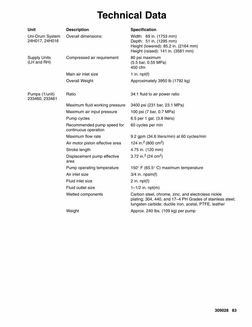
309028 83
Technical DataUnit Description Specification
Uni-Drum System24H017, 24H016
Overall dimensions: Width: 69 in. (1753 mm)Depth: 51 in. (1295 mm)Height (lowered): 85.2 in. (2164 mm)Height (raised): 141 in. (3581 mm)
Supply Units(LH and RH)
Compressed air requirement 80 psi maximum(5.5 bar, 0.55 MPa)450 cfm
Main air inlet size 1 in. npt(f)
Overall Weight Approximately 3950 lb (1792 kg)
Pumps (1/unit)233460, 233461
Ratio 34:1 fluid to air power ratio
Maximum fluid working pressure 3400 psi (231 bar, 23.1 MPa)
Maximum air input pressure 100 psi (7 bar, 0.7 MPa)
Pump cycles 6.5 per 1 gal. (3.8 liters)
Recommended pump speed forcontinuous operation
60 cycles per min
Maximum flow rate 9.2 gpm (34.6 liters/min) at 60 cycles/min
Air motor piston effective area 124 in.2 (800 cm2)
Stroke length 4.75 in. (120 mm)
Displacement pump effectivearea
3.72 in.2 (24 cm2)
Pump operating temperature 150° F (65.5° C) maximum temperature
Air inlet size 3/4 in. npsm(f)
Fluid inlet size 2 in. npt(f)
Fluid outlet size 1–1/2 in. npt(m)
Wetted components Carbon steel, chrome, zinc, and electroless nickleplating; 304, 440, and 17–4 PH Grades of stainless steel;tungsten carbide; ductile iron, acetal, PTFE, leather
Weight Approx. 240 lbs. (109 kg) per pump

84 309028
Graco Standard WarrantyGraco warrants all equipment referenced in this document which is manufactured by Graco and bearing its name to be free from de-fects in material and workmanship on the date of sale to the original purchaser for use. With the exception of any special, extended, orlimited warranty published by Graco, Graco will, for a period of twelve months from the date of sale, repair or replace any part of theequipment determined by Graco to be defective. This warranty applies only when the equipment is installed, operated and maintainedin accordance with Graco’s written recommendations.
This warranty does not cover, and Graco shall not be liable for general wear and tear, or any malfunction, damage or wear caused byfaulty installation, misapplication, abrasion, corrosion, inadequate or improper maintenance, negligence, accident, tampering, or sub-stitution of non–Graco component parts. Nor shall Graco be liable for malfunction, damage or wear caused by the incompatibility ofGraco equipment with structures, accessories, equipment or materials not supplied by Graco, or the improper design, manufacture,installation, operation or maintenance of structures, accessories, equipment or materials not supplied by Graco.
This warranty is conditioned upon the prepaid return of the equipment claimed to be defective to an authorized Graco distributor forverification of the claimed defect. If the claimed defect is verified, Graco will repair or replace free of charge any defective parts. Theequipment will be returned to the original purchaser transportation prepaid. If inspection of the equipment does not disclose any defectin material or workmanship, repairs will be made at a reasonable charge, which charges may include the costs of parts, labor, andtransportation.
THIS WARRANTY IS EXCLUSIVE, AND IS IN LIEU OF ANY OTHER WARRANTIES, EXPRESS OR IMPLIED, INCLUDING BUTNOT LIMITED TO WARRANTY OF MERCHANTABILITY OR WARRANTY OF FITNESS FOR A PARTICULAR PURPOSE.
Graco’s sole obligation and buyer’s sole remedy for any breach of warranty shall be as set forth above. The buyer agrees that no otherremedy (including, but not limited to, incidental or consequential damages for lost profits, lost sales, injury to person or property, or anyother incidental or consequential loss) shall be available. Any action for breach of warranty must be brought within two (2) years of thedate of sale.
GRACO MAKES NO WARRANTY, AND DISCLAIMS ALL IMPLIED WARRANTIES OF MERCHANTABILITY AND FITNESS FORA PARTICULAR PURPOSE, IN CONNECTION WITH ACCESSORIES, EQUIPMENT, MATERIALS OR COMPONENTS SOLDBUT NOT MANUFACTURED BY GRACO. These items sold, but not manufactured by Graco (such as electric motors, switches,hose, etc.), are subject to the warranty, if any, of their manufacturer. Graco will provide purchaser with reasonable assistance in mak-ing any claim for breach of these warranties.
In no event will Graco be liable for indirect, incidental, special or consequential damages resulting from Graco supplying equipmenthereunder, or the furnishing, performance, or use of any products or other goods sold hereto, whether due to a breach of contract,breach of warranty, the negligence of Graco, or otherwise.
FOR GRACO CANADA CUSTOMERSThe parties acknowledge that they have required that the present document, as well as all documents, notices and legal proceedingsentered into, given or instituted pursuant hereto or relating directly or indirectly hereto, be drawn up in English. Les parties reconnais-sent avoir convenu que la rédaction du présente document sera en Anglais, ainsi que tous documents, avis et procédures judiciairesexécutés, donnés ou intentés à la suite de ou en rapport, directement ou indirectement, avec les procedures concernées.
Graco InformationFor the latest information about Graco products, visit www.graco.com.
TO PLACE AN ORDER, contact your Graco distributor, or call to identify the nearest distributor:Phone: 612–623–6921 or Toll Free 1–800–328–0211 Fax: 612–378–3505
All written and visual data contained in this document reflects the latest product information available at the time of publication.Graco reserves the right to make changes at any time without notice.
Original Instructions. This manual contains English. MM 309028
Graco Headquarters: MinneapolisInternational Offices: Belgium, China, Japan, Korea
GRACO INC. AND SUBSIDIARIES � P.O. BOX 1441 � MINNEAPOLIS MN 55440–1441 � USACopyright 2000, Graco Inc. All Graco manufacturing locations are registered to ISO 9001.
www.graco.comRevised 09/2011