UNDERWATER WIRELESS COMMUNICATION
28
Page | 1 Underwater Wireless Communications While wireless communication technology today has become part of our daily life, the idea of wireless undersea communications may still seem far-fetched. However, research has been active for over a decade on designing the methods for wireless information transmission underwater. Human knowledge and understanding of the world’s oceans, which constitute the major part of our planet, rests on our ability to collect information from remote undersea locations. The major discoveries of the past decades, such as the remains of Titanic, or the hydro-thermal vents at bottom of deep ocean, were made using cabled submersibles. Although such systems remain indispensable if high-speed communication link is to exists between the remote end and the surface, it is natural to wonder what one could accomplish without the burden (and cost) of heavy cables. Hence the motivation, and our interest in wireless underwater communications. Together with sensor technology and vehicular technology, wireless communications will enable new applications ranging from environmental monitoring to gathering of oceanographic data, marine archaeology, and search and rescue missions. The signals that are used to carry digital information through an underwater channel are not radio signals, as electro-magnetic waves propagate only over extremely short distances. Instead, acoustic waves are used, which can propagate over long distances. However, an underwater acoustic channel presents a communication system designer with many difficulties. The three distinguishing characteristics of this channel are frequency- dependent propagation loss, severe multipath, and low speed of sound propagation. None of these characteristics are nearly as pronounced in land-based radio channels, the fact that makes underwater wireless communication extremely difficult, and necessitates dedicated system design.
-
Upload
sushobhan-beheramali -
Category
Education
-
view
1.927 -
download
2
Transcript of UNDERWATER WIRELESS COMMUNICATION

P a g e | 1
Underwater Wireless
Communications
While wireless communication technology today has become part of our daily life, the idea of
wireless undersea communications may still seem far-fetched. However, research has been active for over a decade on designing the methods for wireless information transmission underwater.
Human knowledge and understanding of the world’s oceans, which constitute the major part
of our planet, rests on our ability to collect information from remote undersea locations. The major discoveries of the past decades, such as the remains of Titanic, or the hydro-thermal vents at bottom of deep ocean, were made using cabled submersibles. Although such systems
remain indispensable if high-speed communication link is to exists between the remote end and the surface, it is natural to wonder what one could accomplish without the burden (and
cost) of heavy cables. Hence the motivation, and our interest in wireless underwater communications. Together
with sensor technology and vehicular technology, wireless communications will enable new applications ranging from environmental monitoring to gathering of oceanographic data,
marine archaeology, and search and rescue missions. The signals that are used to carry digital information through an underwater channel are not
radio signals, as electro-magnetic waves propagate only over extremely short distances. Instead, acoustic waves are used, which can propagate over long distances.
However, an underwater acoustic channel presents a communication system designer with many difficulties. The three distinguishing characteristics of this channel are frequency-dependent propagation loss, severe multipath, and low speed of sound propagation. None of
these characteristics are nearly as pronounced in land-based radio channels, the fact that makes underwater wireless communication extremely difficult, and necessitates dedicated
system design.

P a g e | 2

P a g e | 3
Introduction
Acoustic communications is defined as communication methods from one point to another by using acoustic signals. Acoustic signal is the only physical feasible tool that
works in underwater environment. Compared with it electromagnetic wave can only travel in water with short distance due to the high attenuation and absorption effect in underwater environment. It is found that the absorption of electromagnetic energy in
sea water is about 45× f dB per kilo meter, where f is frequency in Hertz. In contrast, the absorption of acoustic signal over most frequencies of interest is about three orders
of magnitude lower. There are some investigations about utilizing optical signal for underwater applications. However, they find out that optical signal can only pass through limited range in very clean water environment (deep water, for example).
Thus, it is not a proper tool for long-distance transmission underwater, or in a not-so clean water, e.g., shallow water, environment.
Underwater Acoustic Networks, including but not limited to, Underwater Acoustic
Sensor Networks (UASNs)and Autonomous Underwater Vehicle Networks (AUVNs), are defined as networks composed of more than two nodes, using acoustic signals to
communicate, for the purpose of underwater applications. UASNs and AUVNs are two important kinds of UANs. The former is composed of many sensor nodes, mostly for a monitoring purpose. The nodes are usually without or with limited capacity to move.
The latter is composed of autonomous or unmanned vehicles with high mobility, deployed for applications that need mobility, e.g., exploration. An UAN can be an
UASN, or an AUVN, or a combination of both.
Fundamentals of Waves
Understanding the first principles of each physical wave used in UWSN wireless communication is critically important. In this section we layout the fundamental
physical properties and critical issues for each of the acoustic and optical wave propagations in underwater environments. We discuss each physical carrier’s
advantages and disadvantages towards efficient underwater wireless communication.
Acoustic Waves Among the types of waves, acoustic waves are used as the primary carrier for underwater wireless communication systems due to the relatively low absorption in
underwater environments. We start the discussion with the physical fundamentals and the implications of using acoustic waves as the wireless communication carrier in
underwater environments.
P a g e | 4
Physical Properties:
An acoustic wave has a number of propagation characteristics that are unique from
other waves, two of which are highlighted below: Propagation velocity: The extremely slow propagation speed of sound through
water is an important factor that differentiates it from electromagnetic propagation. The speed of sound in water depends on the water properties of temperature, salinity and pressure (directly related to the depth). A typical speed of sound in water near the
ocean surface is about 1520 m/s, which is more than 4 times faster than the speed of sound in air, but five orders of magnitude smaller than the speed of light. The speed of
sound in water increases with increasing water temperature, increasing salinity and increasing depth. Most of the changes in sound speed in the surface ocean are due to the changes in temperature. This is because the effect of salinity on sound speed is
small and salinity changes in the open ocean are small. Near shore and in estuaries, where the salinity varies greatly, salinity can have a more significant effect on the
speed of sound in water. As depth increases, the pressure of water has the largest effect on the speed of sound .Under most conditions the speed of sound in water is simple to understand. Sound will travel faster in warmer water and slower in colder water.
Approximately, the sound speed increases 4.0 m/s for water temperature .As the depth of water (therefore also the pressure) increases 1 km, the sound speed increases
roughly 17 m/s. It is noteworthy to point out that the above assessments are only for rough quantitative or qualitative discussions, and the variations in sound speed for a given property are not linear in general.
Absorption: During propagation, wave energy may be converted to other forms and absorbed by the medium. The absorptive energy loss is directly controlled by the
material imperfection for the type of physical wave propagating through it. For acoustic waves, this material imperfection is the inelasticity, which converts the wave energy into heat.
Optical Communication
The present technology of acoustic underwater communication is a legacy technology that provides low-data-rate transmissions for medium-range communication. Data rates
of acoustic communication are restricted to around tens of thousands of kilobits per second for ranges of a kilo meter, and less than a thousand kilobits per second for
ranges up to 100 km, due to severe, frequency-dependent attenuation and surface induced pulse spread. In addition, the speed of acoustic waves in the ocean is approximately 1500 m/s, so that long-range communication involves high latency,
which poses a problem for real-time response, synchronization, and multiple-access protocols. In addition, acoustic waves could distress marine mammals such as dolphins
and whales. As a result, acoustic technology cannot satisfy emerging applications that require around the clock, high-data-rate communication networks in real time. Examples of such applications are networks of sensors for the investigation of climate
change; monitoring biological, biogeochemical, evolutionary, and ecological processes in sea, ocean, and lake environments; and unmanned underwater vehicles used to
control and maintain oil production facilities and harbors.

P a g e | 5
An alternative means of underwater communication is based on optics, wherein high data rates are possible. However, the distance between the transmitter and the
receiver must be short, due to the extremely challenging underwater environment, which is characterized by high multi scattering and absorption. Multi scattering causes
the optical pulse to widen in the spatial, temporal, angular, and polarization domains. Optical signal gets scattered badly underwater, and the absorption is also high. Beside
of these, optical wave transmission requires high precision in pointing the narrow laser beams. In very clean water, e.g., deep sea, blue-green wavelengths may be used for
short-range connection. The advantage of optical signal lies in its high data rate up to 100 m. Up to today, the only practical solution for underwater communication with acceptable range is utilizing acoustic signal, which travels underwater with longer
distance, less attenuation, and higher reliability. However, available bandwidth is extremely limited for acoustic signal. For a very long distance at the order of 1000 km,
the available bandwidth falls below a kHz; while only at very short ranges below about 100 m, more than a hundred kHz of bandwidth may be available. Lack of available bandwidth is the biggest issue for underwater acoustic communication /network. High
bit error rate is common in underwater channels, due to the multi path interference and time-varying nature of underwater acoustic channels.
Engineering counter measures
In this section, we describe the engineering countermeasures that have been developed to address the physical challenges for each wave used as the communication carrier in underwater sensor networks. These are physical layer techniques to achieve point-to point
communication among sensor nodes.
Acoustic Communication
Multicarrier modulation: The idea of multicarrier modulation is to divide the available bandwidth into a large number of overlapping sub bands, so that the waveform
duration for the symbol at each sub band is long compared to the multipath spread of the channel Consequently, inter-symbol interference may be neglected in each sub band, greatly simplifying the receiver complexity of channel equalization.
Precisely due to this advantage, multicarrier modulation in the form of orthogonal frequency division multiplexing (OFDM) has prevailed in recent broadband wireless radio
applications.
Multi-input multi-output techniques: A wireless system that employs multiple transmitters and multiple receivers is referred to as a multiple- input multiple-output
(MIMO) system Hence, MIMO modulation is a promising technology to offer yet another fundamental advance on high data rate underwater acoustic communication.

P a g e | 6
MIMO has been applied in both single carrier transmission and multicarrier transmission.
Optical Communication As pointed out water quality plays a key role in deciding whether optical waves can be
used for underwater communication. As a result, the applicability of optical communication heavily depends on environments. Using the same analogy for acoustic
and electromagnetic waves, we say that optical communication works in the environment- limited region. So far, there are not many commercial activities on underwater optical communication, and no commercial optical modems are available
specifically for underwater. Recent interests in underwater sensor networks and sea floor observatories have greatly stimulated the interest in short-range high-rate optical
communication in water.
Applications: ocean observation
• Environmental monitoring
– climate recording – pollution control
– prediction of natural disasters – oil/gas fields – harbor protection
• Underwater exploration
– discovery of natural resources – marine phenomena – deep-sea archaeology
• Scientific data collection
– oceanography – geo-sciences (physics/chemistry) – marine biology

P a g e | 7
• Search and survey, military and non military
– detection of objects – ocean bottom imaging and
Mapping
Acoustic Modem
Acoustic modems offer the possibility of wireless communication under water. For those who
have dealt with cables in unfavorable ocean environments, this is an elegant solution for
communication. Typical applications for acoustic modems are real time systems or
previously deployed systems where data needs to be periodically downloaded. Despite the
allure of wireless communication, acoustic modems are not without their limitations and
challenges. To help you decide whether an acoustic modem is suitable for your particular
communication needs, we explain these limitations and how they affect your communication
here.
Functional Description
Underwater acoustic communication is relatively slow when compared to radio
communication. This has to do largely with the speed of sound in water which is roughly
1500 meters/second. The result is a relatively low baud rate (typically 9600 baud).
Not only is the medium slow but there are complications with the transmission due to signal
absorption, geometric spreading losses, boundary effects, and multipath to name a few.
Manufacturers have several techniques they employ to handle these challenges. The
techniques come in the form of signal processing, data packaging, and coding schemes. These
techniques, which are not the same for all manufacturers, help ensure reliable communication
and possibly identify bit loss and/or repair these lost portions of data at the receiver end.

P a g e | 8
There are several methods of transmitting data acoustically (i.e. modulation), but the most
common method is the use of spread spectrum. Briefly, this is a method of sending data at
several different frequencies (Multi-Frequency Shifted Key, MFSK) in order to increase data
throughput. Another modulation scheme is the Phase Shifted Key, or PSK; this modulation
scheme permits higher baud rates but is more susceptible to error sources.
The data are packed to ensure that a few errors will not corrupt the entire data message. This
means that large amounts of data are sent as a series of these data packages. A typical data
package is approximately 4 kb. A package contains the data plus additional bytes of data for
identifying the package boundaries, modem identity, checksum, and error correction codes.
Some modems allow for a configuration where a retransmission request is sent from the
receiver if errors are detected in a data package. The implication of lost data is that it must be
retransmitted. This affects the effective baud rate if a modem is operating at a high acoustic
baud rate.
Apart from the modulation schemes and packaging techniques there are also techniques to
minimize the effects of multipath. Multipath is the reception of the same signal several times,
yet slightly delayed from one another. Since the signal is the same frequency and arrives at
more or less the same time, it is challenging to separate the original signal from time delayed
versions overlapping each other.
As the name suggests, multipath is the source of these “different” signals that are reflections of the
original signal from boundaries that lie between the transmitter and receiver. Multipath is most
prominent over long ranges and shallow water, whereby the original signal can bounce between the
surface and bottom before arriving at the receiver. There are a few tricks in use to reduce the effects
of multipath. These are convolutional coding, multipath guard period, and data redundancy.
Convolutional coding is data in a following frame that is capable of correcting up to one
bit errors in the data frame previously sent.

P a g e | 9
Multipath guard is a time delay inserted between data frames. Increasing the delay
between frames reduces the interference from multipath.
Data redundancy is simply the process by which data is retransmitted in the same data
frame.
DEMERITS OF ACOUSTIC MODEM
Range and Depth Communication over short distances (approximately 200 meters) is
quite dependable. This is particularly true for vertical communication in deep waters
with few boundaries. Horizontal communication in shallow waters is increasingly more
challenging as the depth/range aspect ratio becomes smaller. An example of a
challenging scenario is 5 meter depth over a range of 3000 meters.
Clear Line of Sight If you do not have a clear line of sight between the modems, it is
very unlikely that there will be communication between them. It is also unlikely that an
acoustically rigid boundary can be used to reflect energy in order to achieve an indirect
transmission path.
Parts of an acoustic modem:
• DSP Board
• AFE(Analog Front End) Board

P a g e | 10
P a g e | 11
UNDERWATER ACOUSTIC SENSOR
NETWORKS (UW-ASN)
Wired underwater is not feasible in all situations as shown below-:
• Temporary experiments
• Breaking of wires • Significant cost of deployment
• Experiment over long distances. To cope up with above situations, we require underwater wireless communication.
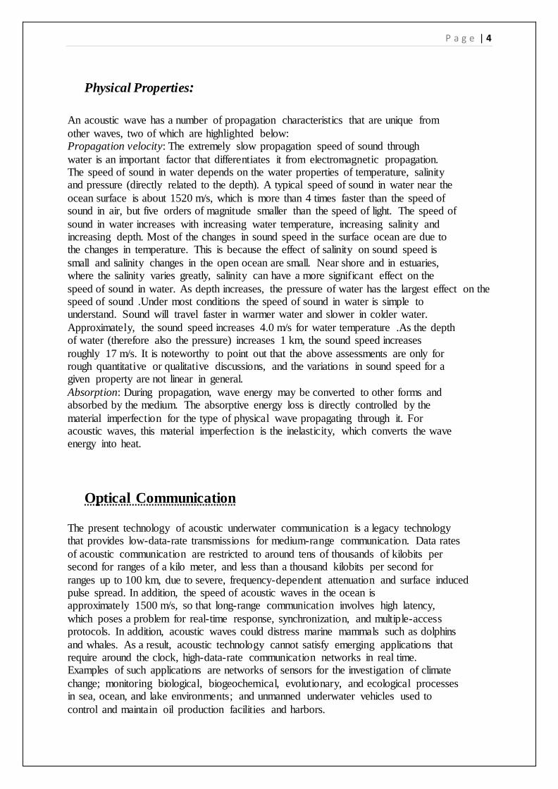
UW-ASN COMMUNICATION ARCHITECTURE
2-D ARCHITECTURE

P a g e | 12
Underwater networks
Integrated networks of instruments, sensors, robots and vehicles will operate together
in a variety of underwater environments
Acoustic networks, navigation and sensing
for multiple autonomous underwater robotic vehicles.

P a g e | 13
ATTACKS AND COUNTER MEASURES

P a g e | 14
Jamming
Method of Attack
• The transmission of data packets continuously so that the wireless channel get
completely blocked.
Countermeasures
• Spread spectrum techniques.
• Sensors can switch to sleep mode
Wormhole Attack

P a g e | 15
Method of attack
False neighborhood relationship are created.
Countermeasures
Estimating the direction of arrival.
Hello Flood Attack
Wireless sensor network have emerged as an important application of the ad-hoc networks
paradigm, such as for monitoring physical environment. These sensor networks have
limitations of system resources like battery power, communication range and processing
capability. Low processing power and wireless connectivity make such networks vulnerable
to various types of network attacks. One of them is hello flood attack, in which an adversary,
which is not a legal node in the network, can flood hello request to any legitimate node and
break the security of WSN. The current solutions for these types of attacks are mainly
cryptographic, which suffer from heavy computational complexity. Hence they are less
suitable for wireless sensor networks. A method based on signal strength has been proposed
to detect and prevent hello flood attack. Nodes have been classified as friend and stranger
based on the signal strength. Short client puzzles that require less computational power and
battery power have been used to check the validity of suspicious nodes.

P a g e | 16
Underwater Sensor Nodes

P a g e | 17
Multi-carrier modulation /
orthogonal frequency division multiplexing
• Available bandwidth divided
into narrow sub-bands: channel appears ideal (flat)
in each sub-band
• OFDM: efficient implementation via FFT
+Low-complexity equalization (frequency-domain) -High sensitivity to frequency
Offset
•High-rate acoustic system is inherently wideband (“UWB”):
Doppler distortion is not uniform across sub-bands

P a g e | 18
Schematic of an integrated subsea wireless system
comprising acoustic, optical, and magnetic induction
systems.

P a g e | 19
Autonomous Underwater Vehicles (AUVs)
An autonomous underwater vehicle (AUV) is a robot which travels underwater without
requiring input from an operator. AUVs constitute part of a larger group of undersea systems
known as unmanned underwater vehicles, a classification that includes non-autonomous
remotely operated underwater vehicles (ROVs) – controlled and powered from the surface by
an operator/pilot via an umbilical or using remote control. In military applications AUVs are
more often referred to simply as unmanned undersea vehicles (UUVs).
The first AUV was developed at the Applied Physics Laboratory at the University of
Washington as early as 1957 by Stan Murphy, Bob Francois and later on, Terry Ewart. The
"Special Purpose Underwater Research Vehicle", or SPURV, was used to study diffusion,
acoustic transmission, and submarine wakes.
Other early AUVs were developed at the Massachusetts Institute of Technology in the 1970s.
One of these is on display in the Hart Nautical Gallery in MIT. At the same time, AUVs were
also developed in the Soviet Union (although this was not commonly known until much
later).

P a g e | 20
Applications Of AUV -
Until relatively recently, AUVs have been used for a limited number of tasks dictated by the
technology available. With the development of more advanced processing capabilities and
high yield power supplies, AUVs are now being used for more and more tasks with roles and
missions constantly evolving.
Commercial
The oil and gas industry uses AUVs to make detailed maps of the seafloor before they start
building sub sea infrastructure; pipelines and sub sea completions can be installed in the most
cost effective manner with minimum disruption to the environment. The AUV allows survey
companies to conduct precise surveys of areas where traditional bathymetric surveys would
be less effective or too costly. Also, post-lay pipe surveys are now possible.

P a g e | 21
Future autonomous underwater
systems: network topologies
• Centralized

P a g e | 22
• Decentralized

P a g e | 23
Depending on the application there two types of Acoustic network .
Centralized network, nodes communicate through a base station that covers one cell.
In a decentralized network, nodes communicate via peer-to-peer.
To accommodate multiple users within a selected network topology, the
communication channel must be shared.
Methods for channel sharing are based on scheduling or on contention .

P a g e | 24
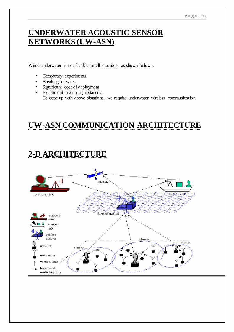
Channel sharing (access regulation) • Deterministic/scheduling
• Multiple access: frequency, time code division (FDMA, TDMA,
CDMA); also space division. • Continuous traffic, fixed number
of users
• Complex, low overhead • Scalability? Spatial reuse for
efficient resource allocation (power, bandwidth).
• Random/contention
• Aloha, Carrier Sensing Multiple Access (CSMA), Multiple access with
Collision Avoidance (MACA) • Bursty traffic, variable number of
Users
• Simple, high overhead (RTS/CTS) • Scalable.
P a g e | 25
LIMITATIONS
• Battery power is limited and usually batteries can not be recharged easily.
• The available bandwidth is severely limited.
• Underwater sensors are prone to failures because of fouling, corrosion, etc.
• Highly affected by environmental and natural factors such as heterogeneities of the water column, variations of sound velocity versus depth, temperature and salinity,
multiple and random sea reflections and significant scattering by fish, bubble clouds and plankton.
P a g e | 26
Open problems and future research
Fundamental questions:
Statistical channel modeling Network capacity
Research areas:
Data compression Signal processing for communications: adaptive modulation / coding
channel estimation / prediction multiple in/out channels (tx/rx arrays)
multi-user communications communications in hostile environment Communication networks:
network layout / resource allocation and reuse network protocols: all layers
network architecture / cross layer optimization
Experimental networks: System specification:
typical vs. application-specific (traffic patterns, performance requirements) optimization criteria (delay, throughput, reliability, energy efficiency) Concept demonstration:
simulation in-water
prototypes
System integration: Cabled observatories
Integration of wireless communications: cabled backbone + mobile nodes = extended reach Wireless extension: acoustical and optical

P a g e | 27
Conclusion
The results presented indicate that networks based on under water optical wireless links are feasible at high data rates for medium distances, up to a hundred meters.
Such networks could serve subsea wireless mobile users.
In addition ,by placing multiple relay nodes between the chief network nodes, messages could traverse very long distances despite severe medium-induced limitations on the transmission ranges of individual links.
Additional improvements to the availability of the network could be achieved by a hybrid
communication system that would include an optical transceiver and an acoustical transceiver.
A hybrid communication system can provide high-data rate transmission by using the optical transceiver.
When the water turbidity is high or the distance between the terminals is large, the system can switch to a low data rate using the acoustic transceiver, thereby increasing the average
data rate and availability.

P a g e | 28
However, the complexity and cost of the system are increased.
In this kind of system, smart buffering and prioritization could help to mitigate short-term data rate reduction.
Many aspects of the proposed system remain to be investigated .Extensive studies should be made of the nature of multiple scattering in different oceanic channels.


![Channel Modelling For Underwater Wireless …ethesis.nitrkl.ac.in/7629/1/191.pdfUWCN. [16] 1.3 Overview of underwater wireless communication Underwater wireless acoustic communication](https://static.fdocuments.in/doc/165x107/5fb283cdf060a866e0329b38/channel-modelling-for-underwater-wireless-uwcn-16-13-overview-of-underwater.jpg)