UNDERWATER EXHAUST - HORIZONTAL - Centek Industries
2
UNDERWATER EXHAUST HORIZONTAL Product Installa.on Guidelines Centek Industries, Inc. 116 Plantation Oak Drive, Thomasville, GA 31792 (229) 2287653 www.centekindustries.com WARNING – These are GUIDELINES ONLY and are NO GUARANTEE of a properly designed and installed exhaust system. Centek’s products are used in a variety of systems and applicaLons. Therefore, it is impossible for Centek to provide specific installaLon instrucLons for all possible configuraLons of exhaust systems that may be incorporated on a marine vessel by the vessel manufacturer. IT IS THE RESPONSIBILITY OF THE BOAT MANUFACTURER TO PROPERLY DESIGN AND INSTALL AN EXHAUST SYSTEM APPROPRIATE FOR THE VESSEL IT MANUFACTURES. The guidelines for the Underwater Muffler are as follows: 1. The Underwater Muffler is a WET marine exhaust muffler. It is designed for use in an exhaust system as appropriately recommended by ABYC (American Boat & Yacht Council) Standard P-1. 2. Hull penetration locations shall be selected by a Naval Architect. 3. Bypass line must exit the hull above the heeled waterline. 4. Refer to ABYC H-27 regarding hull penetrations below the heeled waterline. 5. The Underwater Muffler is designed for gas/water to flow in one direction only. Please note labels on muffler carefully. 6. There must be sufficient distance between the water injection point and placement of the Underwater Muffler to allow adequate cooling of the exhaust gases. The distance will be dependent on the manner of the water injection. Maximum operating temperature should not exceed 350° F. A typical well-designed system should run between 120-188° F. 7. An optional surge chamber may be used as protection against back flow of water up and into the exhaust manifold. Such designs are desirable and can help to reduce the risk of engine damage. See our catalog or website for the various sizes/dimensions of surge chambers available. 8. The Underwater Muffler should be installed in a level position or tipped slightly toward the outlet, with the body rotated so that the installation label is directly on top and the direction of the flow arrow points aft. 9. Making connections: A) Use approved marine exhaust hose for all connections. This will help isolate the muffler and other components from vibration. Do not connect other components to the muffler in a rigid fashion by using adhesives and/or FRP reinforcements. B) DO NOT coat hose or muffler with oil or grease – use water for lubrication. C) Use a minimum of two stainless steel hose clamps per end connection. Tighten clamps by hand with a screwdriver or small wrench. Do not use air wrenches. (continued) Rev 7A
Transcript of UNDERWATER EXHAUST - HORIZONTAL - Centek Industries
UNDERWATER EXHAUST -‐ HORIZONTAL
Product Installa.on Guidelines
Centek Industries, Inc. 116 Plantation Oak Drive, Thomasville, GA 31792
(229) 228-‐7653 www.centekindustries.com
WARNING – These are GUIDELINES ONLY and are NO GUARANTEE of a properly designed and installed exhaust system. Centek’s products are used in a variety of systems and applicaLons. Therefore, it is impossible for Centek to provide specific installaLon instrucLons for all possible configuraLons of
exhaust systems that may be incorporated on a marine vessel by the vessel manufacturer.
IT IS THE RESPONSIBILITY OF THE BOAT MANUFACTURER TO PROPERLY DESIGN AND INSTALL AN EXHAUST SYSTEM APPROPRIATE FOR THE VESSEL IT MANUFACTURES.
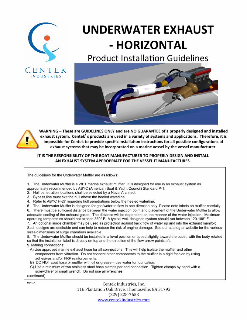
The guidelines for the Underwater Muffler are as follows: 1. The Underwater Muffler is a WET marine exhaust muffler. It is designed for use in an exhaust system as appropriately recommended by ABYC (American Boat & Yacht Council) Standard P-1. 2. Hull penetration locations shall be selected by a Naval Architect. 3. Bypass line must exit the hull above the heeled waterline. 4. Refer to ABYC H-27 regarding hull penetrations below the heeled waterline. 5. The Underwater Muffler is designed for gas/water to flow in one direction only. Please note labels on muffler carefully. 6. There must be sufficient distance between the water injection point and placement of the Underwater Muffler to allow adequate cooling of the exhaust gases. The distance will be dependent on the manner of the water injection. Maximum operating temperature should not exceed 350° F. A typical well-designed system should run between 120-188° F. 7. An optional surge chamber may be used as protection against back flow of water up and into the exhaust manifold. Such designs are desirable and can help to reduce the risk of engine damage. See our catalog or website for the various sizes/dimensions of surge chambers available. 8. The Underwater Muffler should be installed in a level position or tipped slightly toward the outlet, with the body rotated so that the installation label is directly on top and the direction of the flow arrow points aft. 9. Making connections: A) Use approved marine exhaust hose for all connections. This will help isolate the muffler and other components from vibration. Do not connect other components to the muffler in a rigid fashion by using adhesives and/or FRP reinforcements. B) DO NOT coat hose or muffler with oil or grease – use water for lubrication. C) Use a minimum of two stainless steel hose clamps per end connection. Tighten clamps by hand with a screwdriver or small wrench. Do not use air wrenches. (continued)
Rev 7A
Underwater Muffler -‐ Product Installa.on Guidelines -‐
CENTEK 5-YEAR WARRANTY
Unless otherwise specified, Centek warrants its products for a period of five years from the date of original sale. This limited warranty is in lieu of all other expressed or implied
warranties such as warranty of merchantability or fitness for a particular use or the results or effects of such use.
Centek’s liability is limited to the replacement or repair of the Products and such liability will not exceed the original purchase price.
A full copy of all the terms and conditions of Centek’s warranty is available online at www.centekindustries.com/warranty.pdf or will be furnished upon request.
Warning! Gasoline engines produce dangerous levels of carbon monoxide that will pass through this product as part of a properly designed and installed exhaust system. Per ABYC A-24 Standards, this product must be used
in conjunction with working carbon monoxide detectors installed in the boat’s living quarters.
(continued)
9. Although the muffler itself is very light, the water content is significant in weight. Therefore, mufflers should be firmly supported and strapped at the major diameter of both end caps. The Underwater Muffler is recommended for both gasoline and diesel propulsion and generator engines. It is designed to withstand many times the normal operating pressures. However, this does not mean that it can withstand the extreme instantaneous pressures associated with back-fire. WARNING! Should a back-fire occur, an immediate and thorough inspection of the entire exhaust system is recommended.