Understanding Dancer Tension Control Systems - tappi.org · Device + Dancer Weight M = Mass A =...
20
Presented by: Darrell Whiteside Director Sales-Tension Control MAGPOWR Understanding Dancer Tension Control Systems
Transcript of Understanding Dancer Tension Control Systems - tappi.org · Device + Dancer Weight M = Mass A =...

Presented by: Darrell WhitesideDirector Sales-Tension Control
MAGPOWR
Understanding Dancer Tension Control Systems

2
• Manual systems
» Closed loop» Open loop
• Automatic systems
System Types

3
Feedbac
k
Control adjusts brake torque up or down
B
Sensor measures tension
LC
Load Cell System
4
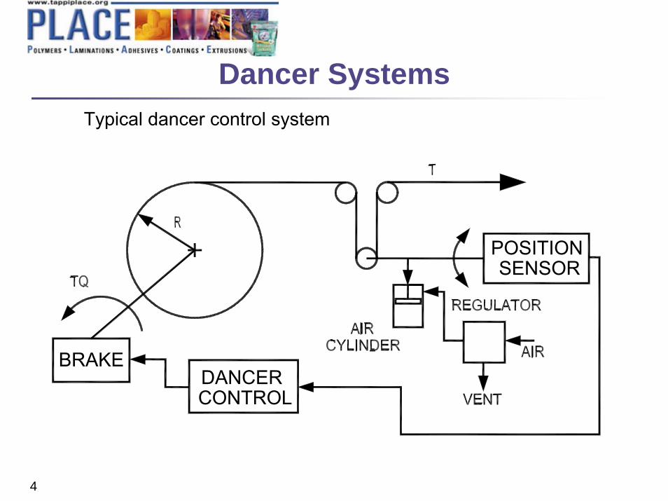
DANCERCONTROL
BRAKE
SENSORPOSITION
Typical dancer control system
Dancer Systems

5
Why Use Dancers?
Accumulation for Out-of-Round Rolls
Accumulation for Indexing Applications
Accumulation for Zero Speed Splicing
6
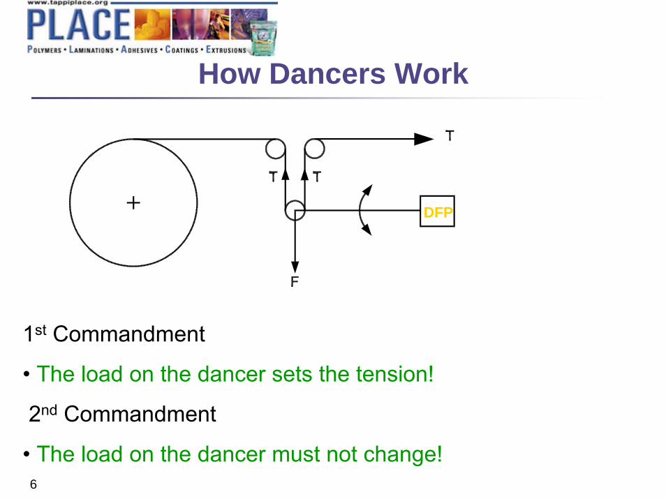
DFP
How Dancers Work
1st Commandment
• The load on the dancer sets the tension!
2nd Commandment
• The load on the dancer must not change!

7
+ MA + DV + KX
T T
L
M
X
2T = L
T = Web TensionL = Load Set by Loading
Device + Dancer WeightM = MassA = AccelerationD = Damping FactorV = VelocityK = Spring RateX = Deflection
Ideal Condition: 2T = LHow do we get there?
Forces (F) on a Dancer
00≈0
8
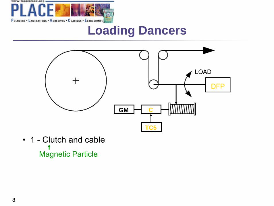
Loading Dancers
LOAD
DFP
TC5
CGM
• 1 - Clutch and cable
Magnetic Particle

9
1. Clutch and cable
Magnetic Particle2. Pneumatic cylinder and regulator
Use a rolling diaphragm type cylinder•Bellafram•Illinois Pneumatic•Control Air
Quick relieving
DFP
Loading Dancers
Air In

10
1 - Clutch and cableMagnetic Particle
2 - Pneumatic cylinder and regulatorUse a rolling diaphragm type cylinder
3 – SpringsLoad changes as spring is stretched from rest position
4 - Weights (Counter balance)They add mass
5 - Shock absorbersLoad changes with velocity of dancer
DFP
Quick relieving
kg
Loading Dancers

11
Dancer Arm:• Should be long enough• Should be positioned far enough away from adjacent
idler rolls so the load on the dancer arm does not change• Arcs of 30o- 90o are common
Loading Device should be:• Independent of position• Independent of velocity• Independent of direction of motion
2TL ≠
Effect of Position, Velocity & Direction
of Motion on Dancer
12
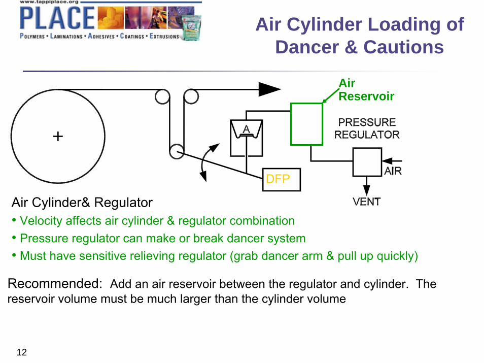
DFP
Air Cylinder& Regulator• Velocity affects air cylinder & regulator combination• Pressure regulator can make or break dancer system• Must have sensitive relieving regulator (grab dancer arm & pull up quickly)
Air Reservoir
Recommended: Add an air reservoir between the regulator and cylinder. The reservoir volume must be much larger than the cylinder volume
Air Cylinder Loading ofDancer & Cautions
13
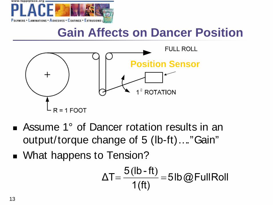
Position Sensor
Assume 1° of Dancer rotation results in an output/torque change of 5 (lb-ft)….”Gain”What happens to Tension?
RollFull@lb5(ft) 1
ft-lb5ΔT ==)(
Gain Affects on Dancer Position

14
Gain Affects on Dancer Position
CORE
R = .25 FOOT1 ROTATIONO
Assume 1° of Dancer rotation results in an output/torque change of 5 (lb-ft)….”Gain”What happens to Tension?
Core@lb20(ft) 0.25ft-lb5ΔT ==
)(

15
Summary of GainAffects on Dancer Position
Review Roll DimensionsFull Roll Diameter of 1 (ft)Core Diameter of 0.25 (ft)
Tension Change Due to Roll Diameter Reduction5 lb @ Full Roll20 lb @ Core
} Roll Build Ratio of 4:1
}Tension Changes by the Roll Build Ratio, but Inertia (Unwind Gain) Changes by R3, or 1:64
Larger Roll Build Ratios are Common!

16
Evolution of Gain(System Gain = Control Gain + Unwind Gain)
“The Past”w/o Gain Compensation
Full
Roll
Core
Diameter
Gai
n
System Gain w/o CompensationControl Gain w/o CompensationUnwind Gain

17
Methods to MinimizeGain Affects
Reduce the Roll Build RatioImpossible!!!!
Operate Dancer Control with Low GainSlow Response (Sluggish)Dancer May Hit Stops
Set Gain Proportionate to Roll SizeUse a Gain Compensating Dancer Control

18
Evolution of Gain(System Gain = Control Gain + Unwind Gain)
“The Past”
w/o Gain Compensation
Full
Rol
l
Core
Diameter
Gai
n
System Gain w/o CompensationControl Gain w/o CompensationUnwind Gain
“Today”
w/ Gain Compensation
Diameter
System Gain w/ Compensation Control Gain w/ CompensationUnwind Gain
19
Summary
Use Dancer Systems for AccumulationOut-of-Round RollsIndexingZero Speed Splicing
Use a Quality “Non-Stick” Rolling Diaphragm Air CylinderMake the Arm as Light as possibleNo Springs, Dampers or WeightsFor Large Roll Builds use a Gain Compensating Control

20
Thank you!
Darrell WhitesideDirector of Sales- Tension Control [email protected]
Please remember to turn in your evaluation sheet...