Under PCAP Polarity Reject Signal1 - Keysight Automated X-ray Inspection Understanding the PCAP...
4
1 Automated X-ray Inspection Understanding the PCAP Polarity Reject Signal Software Revisions: 5.x – 8.x The PCAP misalignment algorithm includes functionality to determine if a PCAP has been rotated 180 degrees (reversed) from the desired placement. This polarity test is controlled by the POLARITY_REJECT threshold, but understanding this threshold can at first be confusing. It is important to note that proper setup of the CAD data must be done for this algorithm to work correctly. PCAPS must be defined with the slug located closest to pin 2 of the device. Failure to correctly set up the CAD data in this manner will cause problems with both the polarity test as well as the test for a missing PCAP. Refer to the ASAP guidelines for proper setup and tuning of the PCAP device type. Figure 1 shows a thickness profile of a properly aligned PCAP. Note that the slug is located nearest pin 2 in the profile. Figure 1 – Properly Aligned PCAP Thickness Profile In order to determine if a PCAP is reversed, the 5DX creates a “Reflected Profile” from the thickness profile. Moving from pin 1 and working towards the center of the device, a Reflected Profile graph is created by subtracting the thickness value of the corresponding point near pin 2 from the thickness value near pin 1. This profile is ALWAYS created by subtracting pin 2 values from pin 1 values, regardless of how the package has been placed.
Transcript of Under PCAP Polarity Reject Signal1 - Keysight Automated X-ray Inspection Understanding the PCAP...
1
Automated X-ray Inspection Understanding the PCAP Polarity Reject Signal
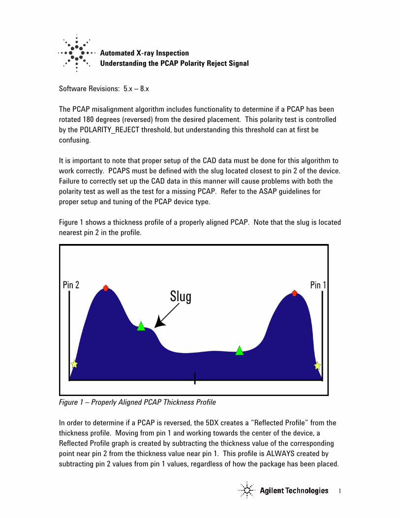
Software Revisions: 5.x – 8.x The PCAP misalignment algorithm includes functionality to determine if a PCAP has been rotated 180 degrees (reversed) from the desired placement. This polarity test is controlled by the POLARITY_REJECT threshold, but understanding this threshold can at first be confusing. It is important to note that proper setup of the CAD data must be done for this algorithm to work correctly. PCAPS must be defined with the slug located closest to pin 2 of the device. Failure to correctly set up the CAD data in this manner will cause problems with both the polarity test as well as the test for a missing PCAP. Refer to the ASAP guidelines for proper setup and tuning of the PCAP device type. Figure 1 shows a thickness profile of a properly aligned PCAP. Note that the slug is located nearest pin 2 in the profile.
Figure 1 – Properly Aligned PCAP Thickness Profile In order to determine if a PCAP is reversed, the 5DX creates a “Reflected Profile” from the thickness profile. Moving from pin 1 and working towards the center of the device, a Reflected Profile graph is created by subtracting the thickness value of the corresponding point near pin 2 from the thickness value near pin 1. This profile is ALWAYS created by subtracting pin 2 values from pin 1 values, regardless of how the package has been placed.
2
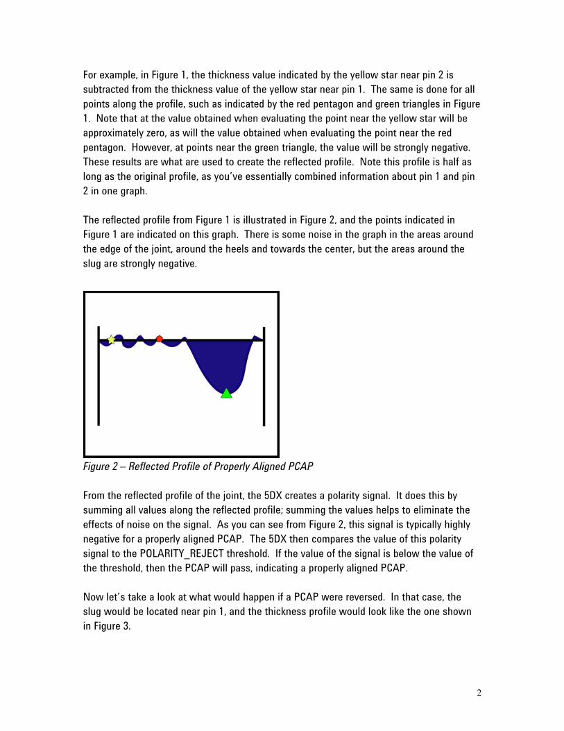
For example, in Figure 1, the thickness value indicated by the yellow star near pin 2 is subtracted from the thickness value of the yellow star near pin 1. The same is done for all points along the profile, such as indicated by the red pentagon and green triangles in Figure 1. Note that at the value obtained when evaluating the point near the yellow star will be approximately zero, as will the value obtained when evaluating the point near the red pentagon. However, at points near the green triangle, the value will be strongly negative. These results are what are used to create the reflected profile. Note this profile is half as long as the original profile, as you’ve essentially combined information about pin 1 and pin 2 in one graph. The reflected profile from Figure 1 is illustrated in Figure 2, and the points indicated in Figure 1 are indicated on this graph. There is some noise in the graph in the areas around the edge of the joint, around the heels and towards the center, but the areas around the slug are strongly negative.
Figure 2 – Reflected Profile of Properly Aligned PCAP From the reflected profile of the joint, the 5DX creates a polarity signal. It does this by summing all values along the reflected profile; summing the values helps to eliminate the effects of noise on the signal. As you can see from Figure 2, this signal is typically highly negative for a properly aligned PCAP. The 5DX then compares the value of this polarity signal to the POLARITY_REJECT threshold. If the value of the signal is below the value of the threshold, then the PCAP will pass, indicating a properly aligned PCAP. Now let’s take a look at what would happen if a PCAP were reversed. In that case, the slug would be located near pin 1, and the thickness profile would look like the one shown in Figure 3.
3
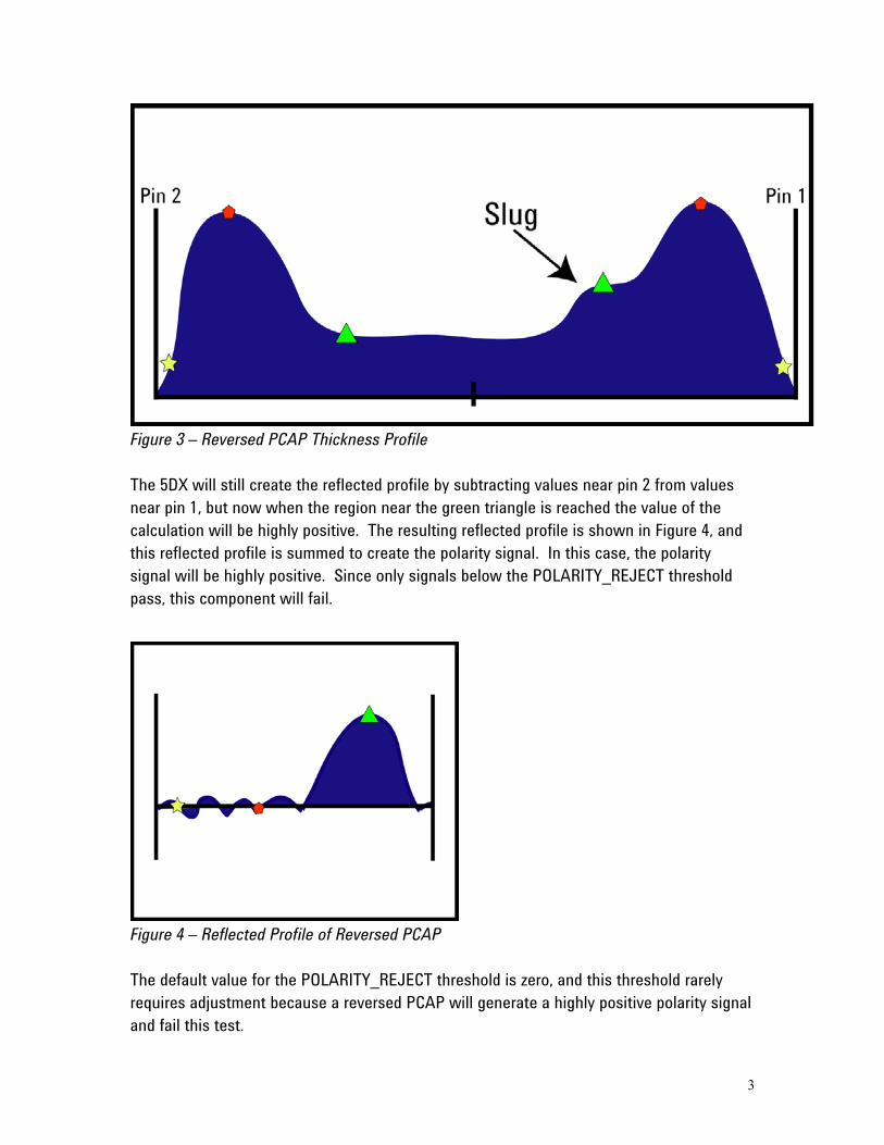
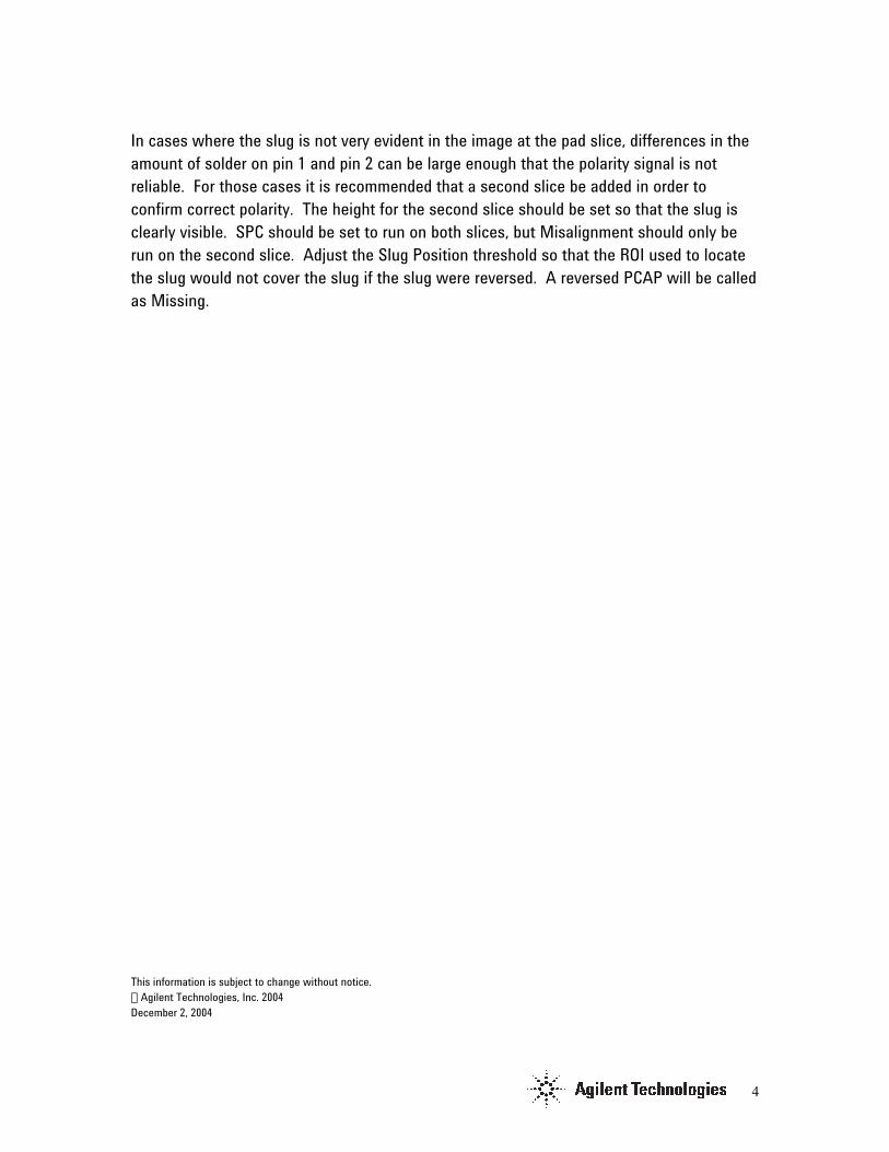
Figure 3 – Reversed PCAP Thickness Profile The 5DX will still create the reflected profile by subtracting values near pin 2 from values near pin 1, but now when the region near the green triangle is reached the value of the calculation will be highly positive. The resulting reflected profile is shown in Figure 4, and this reflected profile is summed to create the polarity signal. In this case, the polarity signal will be highly positive. Since only signals below the POLARITY_REJECT threshold pass, this component will fail.
Figure 4 – Reflected Profile of Reversed PCAP The default value for the POLARITY_REJECT threshold is zero, and this threshold rarely requires adjustment because a reversed PCAP will generate a highly positive polarity signal and fail this test.
4
In cases where the slug is not very evident in the image at the pad slice, differences in the amount of solder on pin 1 and pin 2 can be large enough that the polarity signal is not reliable. For those cases it is recommended that a second slice be added in order to confirm correct polarity. The height for the second slice should be set so that the slug is clearly visible. SPC should be set to run on both slices, but Misalignment should only be run on the second slice. Adjust the Slug Position threshold so that the ROI used to locate the slug would not cover the slug if the slug were reversed. A reversed PCAP will be called as Missing. This information is subject to change without notice.
Agilent Technologies, Inc. 2004 December 2, 2004