
Under Ground Cables
29
Undergrounding of Transmission Cables and Their Types Punjab EDUSAT Socity Presented BY Muhammad ali(UW-11-EE-BSC-20) Haseeb Hassan(UW-11-EE-BSC-16) Faisal mumtaz(UW-11-EE-BSC-60) 1
-
Upload
fawad-nawaz-ghuman -
Category
Documents
-
view
14 -
download
2
description
presentation
Transcript of Under Ground Cables

Undergrounding of Transmission Cables and
Their Types
Punjab EDUSAT Socity
Presented BY Muhammad ali(UW-11-EE-BSC-20)
Haseeb Hassan(UW-11-EE-BSC-16) Faisal mumtaz(UW-11-EE-BSC-60)
1
Introduction
Punjab EDUSAT Socity
• An underground cable essentially consists of one or more conductors covered with suitable insulation and surrounded by a protecting cover. The interference from external disturbances like storms, lightening, ice, trees etc. should be reduced to achieve trouble free service. The cables may be buried directly in the ground, or may be installed in ducts buried in the ground.
2

• Conductor• Paper insulation• Metal sheath• Bedding• Armour• Serving
Cable Structure

Properties of Insulating Material
Punjab EDUSAT Socity
High resistivity.High dielectric strength.Low water absorption.Non – inflammable.Chemical stability.High mechanical strength. .High tensile strength and plasticity.
4
Insulating Materials for Cables
Punjab EDUSAT Socity
1. Rubber
2.Varnished Cambric
3.Impregnated Paper
4. Polyvinyl chloride (PVC)
5.XLPE (Cross Linked Poly-ethene)
5

CLASSIFICATION OF CABLES
Punjab EDUSAT Socity
• Low tension (L.T) ----- up to 1000V
• High tension (H.T) ----- up to 11, 000V
• Super tension (S.T) ---- from 22KV to 33KV
• Extra high tension (E.H.T) cables --- from 33KV to 66KV
• Extra super voltage cables ------beyond 132KV
6

Low Tension Cable
It consists of one circular core of tinned stranded copper (or aluminium) insulated by layers of impregnated paper.
The insulation is surrounded by a lead sheath which prevents the entry of moisture into the inner parts.
In order to protect the lead sheath from corrosion, an overall serving of compounded fibrous material (jute etc.) is provided.
04/22/23 Punjab EDUSAT Socity

• High-voltage cables differ from lower-voltage cables in that they have additional internal layers in the insulation jacket around the conductor.
• used upto 11 kV
High tension cable(H.T)

Extra High Tension Cable
Punjab EDUSAT Socity 9

Cables for 3-phase • The following types of cables are generally used for 3-phase
service :• 1. Belted cables — upto 11 kV• 2. Screened cables — from 22 kV to 66 kV• 3. Pressure cables — beyond 66 kV.
04
/22
/23
WE
C

Belted Cables
Punjab EDUSAT Socity
• In these cables the conductors are wrapped with oil impregnated paper.
• These can be used for voltages up to 11KV or in some cases can be used up to 22KV.
• As the insulation resistance of paper is quite small along the layer leakage current causes local heating, resulting breaking of insulation at any moment
11

3-core belted Cable
Punjab EDUSAT Socity 12
3- Core Cables
Punjab EDUSAT Socity
• Screened Cables• These can be used up to 33kv but in certain cases can be
extended up to 66kv.
• Pressurized Type Cables• When the operating voltages are greater than 66 kV and up to
230 kV, pressure cables are used. In such cables,in order to avoid air to enter the cable pressurized gas or oil is ued.
• Gas pressure cables are used up to 275KV.• Oil filled cables are used up to 500KV.
13

3- Core Cables
Punjab EDUSAT Socity
• Oil Filled Cables(upto 500kv)• In such types of cables, channels or ducts are provided in the
cable for oil circulation.
14

Gas Pressure Cables
Punjab EDUSAT Socity
In these cables an inert gas like nitrogen is used to exert pressure on paper dielectric to prevent void formation..
15

Laying of underground cables
There are three main methods of laying underground cables :Direct layingDraw-in-systemSolid-system
Direct laying method
• In direct laying method, the cables with steel tape or wire armouring are laid directly as they afford excellent protection from mechanical injury. This method of the laying underground cables is simple and cheap and in much use.
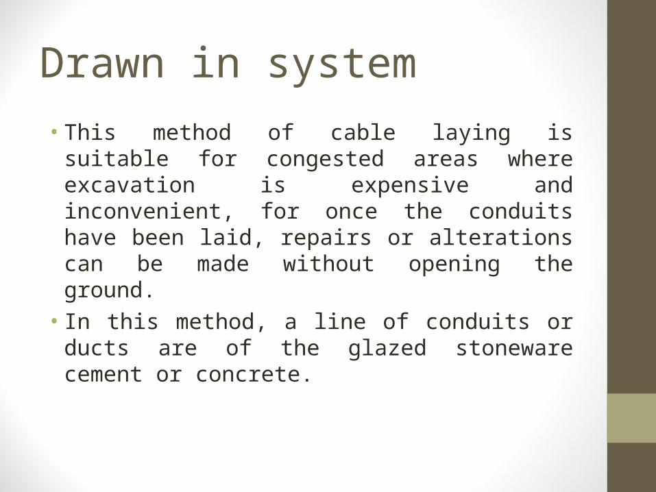
Drawn in system
• This method of cable laying is suitable for congested areas where excavation is expensive and inconvenient, for once the conduits have been laid, repairs or alterations can be made without opening the ground.
• In this method, a line of conduits or ducts are of the glazed stoneware cement or concrete.

Solid system
• In this method of laying, the cable is laid in open pipes or troughs dug out in earth along the cable route. The troughing is of cast iron, stoneware, asphalt or treated wood.

TYPES OF CABLE FAULTS
Punjab EDUSAT Socity
Cables are generally laid in the ground or in ducts in the underground distribution system. For this reason, there are little chances of faults in underground cables. However, if a fault does occur it is difficult to locate and repair the fault because conductors are not visible. Nevertheless, the following are the faults most likely to occur in underground cables
1) open circuit fault2) short circuit fault
20

OPEN CIRCUIT FAULTS
Punjab EDUSAT Socity
• When there is a break in the conductor of a cable, it is called open circuit fault.
• The open circuit fault can be checked by megger. For this purpose, the three conductors of the 3-core cable at the far end are shorted and earthed.
• The resistance between each conductor and earth is measured by a megger and it will indicate zero resistance in the circuit of the conductor that is not broken.
• However, if the conductor is broken, the megger will indicate infinite resistance in its circuit
21

SHORT CIRCUIT FAULTS
Punjab EDUSAT Socity
• When two conductors of a multi-core cable come in electrical contact with each other due to insulation failure, it is called a short circuit fault.
• Again, we can seek the help of a megger to check this fault.• For this purpose the two terminals of the megger are
connected to any two conductors. • If the megger gives zero reading, it indicates short circuit fault
between these conductors.• The same steps is repeated for other conductors taking two a
time.
22

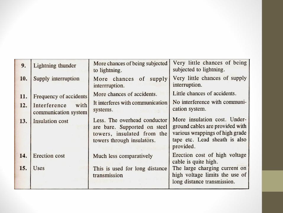
Compaison between overhead and underground system

Bottlenecks
Punjab EDUSAT Socity
1.) Installation cost
2.) Underground line capacitance for power cables is far higher than overhead line capacitance.o Wires are closer to each othero Wires are closer to the earth (within a few inches).
3.)Occurance of Ferranti effect
25

Pros &Cons
• Pros
– Less liable to damage through storms or lighting
– Low maintenance cost
– Less chances of faults
– Small voltage drops
• Cons
– The major drawback is that they have greater installation
cost and introduce insulation problems at high voltages
compared with equivalent overhead system.
04
/22
/23
WE
C

Future Recommendation• Generating station should be installed nearer to consume side
in order to reduce distance and minimize loss due to ferranty effect in underground system.
04
/22
/23
Po
we
r T
ran
smis
sio
n
Conclusion• Undergrounding can increase the initial costs of electric power
transmission and distribution but may decrease operational costs over the lifetime of the cables.
• Due to undergrounding we can see Much less subject to conductor theft, illegal connections.
• Hazadious accidents can be reduced by installing them.
04
/22
/23

Punjab EDUSAT Socity
THANKS
29


