
UNCLASSIFIED AD NUMBER LIMITATION CHANGES · UNCLASSIFIED AD NUMBER LIMITATION CHANGES ... The...
48
UNCLASSIFIED AD NUMBER LIMITATION CHANGES TO: FROM: AUTHORITY THIS PAGE IS UNCLASSIFIED AD909437 Approved for public release; distribution is unlimited. Distribution authorized to U.S. Gov't. agencies only; Test and Evaluation; 13 APR 1973. Other requests shall be referred to Department of the Army Attn: DARD-ZCA, Washington, DC 20310. DA ltr 10 Aug 1973
Transcript of UNCLASSIFIED AD NUMBER LIMITATION CHANGES · UNCLASSIFIED AD NUMBER LIMITATION CHANGES ... The...

UNCLASSIFIED
AD NUMBER
LIMITATION CHANGESTO:
FROM:
AUTHORITY
THIS PAGE IS UNCLASSIFIED
AD909437
Approved for public release; distribution isunlimited.
Distribution authorized to U.S. Gov't. agenciesonly; Test and Evaluation; 13 APR 1973. Otherrequests shall be referred to Department of theArmy Attn: DARD-ZCA, Washington, DC 20310.
DA ltr 10 Aug 1973

■ ^1- 1
I (K
I
To ASb$ «#■» fn'IK-
'.,■*■ -■■-:;-.^ ■■*:'"■.*■■-■■:';,>', ■ ,: -:■' - -.,... .r.;.o. ■
EMPLOYMENT OF A SPIN STABILIZED
ARTILLERY SHELL
TO OBTAIN RECONNAISSANCE IMAGERY
Paul W. Kruse Army Scientific Advisory Panel
June, 1971
X

G£ &MIJL- tf^-fttf-y Oiairlbutlon llsited to U.S. Sev»t. agencies onlyi
I; |©St and Bvaluaiir.ü ; ^-» ^ "^.. . Ot&«r request« | for this dooumect must fee referred ^o
^
^ 313

I
[ ^
EMPLOYMENT OF A SPIN STABILIZED ARTILLERY SHELL
TO OBTAIN RECONNAISSANCE IMAGERY
faul W. Kruse
Army Scientific Advisory Panel
June, 1971
L L
Distribution limited to b.S. Gov't. agencies only Test and Evaluation j/J ^^ /97J Otner requests for this document must be referred to
D D i a j « c —
•.1%' > '
U. J* if»i S»«** ^-ar^
HÜ«

I
ABSTRACT
The concept of employing an expendable spin stabilized artillery
shell containing a simple optical system to obtain reconnaissance imagery
has been suggested by Dr. Marvin Lasser. This paper provides an
initial examination of the technical feasibility of the concept. Three
geometrical scanning configurations are considered; a side-looking one
is analyzed in detail. The requirement for time independent contiguous
mapping, in which each scanning line must touch its neighbors, is
analyzed. Data on the ballistics of a 203mm round fired at a 45° angle
to a range of 16,700 meters are introduced into the equations. It is
found that for this particular trajectory the time independent contiguous
mapping requirement can be met over a 1 kilometer horizontal distance near
apogee. The ground resolution for this trajectory is found to be sufficiently
good for use against targets such as vehicles, buildings, roads, and groups
of individuals which lie beneath the round at apogee. Analysis of photo-
metric considerations reveals adequate signal-to-noise ratio for use beneath
a cloud cover during daylight. Because the initial examination reveals
the concept to be feasible, additional studies are recommended.
I

L L
TABLE OF CONTENTS
1.0 INTRODUCTION
Page
I ■. 1.1 Statement of the Problem r 1
1.2 Ballistic Data 2
t 2.0 OPTICAL CONFIGUEATIONS 6
i
I 2.1 Description 6
* 2.2 Discussion 9
i I. 3.0 PERFORMANCE CALCULATIONS 12
I 3.1 Geometrical Considerations 16
3»1.1 Time Independent Contiguous Mapping 16
I 3.1.2 Dwell Time 23
3.1.3 Ground Resolution 24
I. 3.2 Photometric Considerations 27
| 3.2.1 Properties of Silicon Photocells 28
' 3.2.2 Signal-to-Noise Ratio 30
and Minimum Detectable Contrast
I 4.0 DISCUSSION AND SUMMARY 35
I 5.0 RECOMMENDATIONS 37
, REFERENCES 39

LIST OF FIGURES
FIGURE PAGE
1. TRAJECTORY OF 203MM ROUND 4
2. DEPENDENCE OF ASPECT ANGLE UPON RANGE 5
3. DEPENDENCES OF SPIN RATE AND HORIZONTAL 7
COMPONENT OF VELOCITY UPON RANGE
4. SIDE LOOKING CONFIGURATION 8
5. FORWARD LOOKING CONFIGURATION 10
6. AXIAL CONFIGURATION 11
7. INTERSECTION OF FIELD OF VIEW OF SIDE LOOKING CONFIGURATION 13
WITH EARTH PLANE
8. INTERSECTION. OF FIELD OF VIEW OF FORWARD LOOKING CONFIGURATION 14
WITH EARTH PLANE-PARABOLIC CASE
9. INTERSECTION OF FIELD OF VIEW OF FORWARD LOOKING CONFIGURATION 15
WITH EARTH PLANE-ELLIPTICAL CASE
10. INTERSECTION OF FIELD OF VIEW WITH EARTH PLANE (TRACK) AS A 19
FUNCTION OF HORIZONTAL DISTANCE OF SHELL FROM LAUNCH POINT (RANGE)
11. DEPENDENCE OF V cos29 /hr UPON RANGE 21
12. SCANNING GEOMETRY PERPENDICULAR TO FLIGHT PATH 25
13. GROUND RESOLUTION AS A FUNCTION OF RANGE 26
14. SPECTRAL RESPONSE OF SILICON PHOTODIODE; SOLAR SPECTRUM AT 29 S'JIFACE OF THE EARTH
15. GEOMETRY FOR PHOTOMETRIC ANALYSIS 32^
I

L I
LIST OF TABLES
TABLE PAGE
1. BALLISTIC DATA: STANDARD 203MM M106 ROUND,
ZONE 7, MUZZLE VELOCITY 1950 FT/SEC, WEIGHT 200 LBS.,
ZERO WIND, 45° ELEVATION, FIRED NORTH FROM EQUATOR
AT SEA LEVEL, IMPACT AT SEA LEVEL
2. VALUES OF PERTINENT PARAMETERS CALCULATED FROM
DATA IN TABLE 1
18
i
-1-
EMPLOYMENT 0? A SPIN STABILIZED ARTILLERY
SHELL TO OBTAIN RECONNAISSANCE IMAGERY
Paul W. Kruse
Army Scientific Advisory Panel
1.0 INTRODUCTION
1.1 Statement of the Problem
i
Dr. Marvin Lasser, Chief Scientist, U. S. Army, has suggested
employing a spin stabilized artillery shell containing an optical system
to obtain reconnaissance imagery of terrain. The concept involves use
of the spin to p'rovide a scanning action similar to that of an aircraft-
mounted mechanically scanned strip mapper. That is to say, as the round
spins in flight, the field of view of the optical system looking outward
describes a spiral in space which intercepts the earth plane. Point-to-
point variations in the solar radiation reflected from the earth (or
thermal radiation emitted by the earth) which are intercepted by the
scanning system :and focused on a photocell cause a time dependent photo-
signal. This signal is telemetered back to a station near the firing
site, where the imagery is reconstructed to provide a photo of the terrain
overflown.
Because each round fired would be destroyed, a kc?y requirement is
low unit cost. If cost were no consideration, a fin stabilized projectile
mounting a TV camera could be employed. The spinning round concept must
result in a much less expensive approach. Ideally, a round having the
same ballistic properties as a conventional H. E. round would employ
inexpensive optics, solid state photosensors, and integrated circuits
in place of the safing, arming, fuzing, and explosive sections. Relatively
expensive components such as gyros and gimbals would not be used. Complex-
ity, if required, would be in the ground based telemetry receiver, imagery
decoder, and display, rather than in the round itself.
This paper constitutes a first look at the problem. It presents a
simplified analysis which identifies those areas requiring more detailed
studies. Both the geometric and the photometric aspects of the problem
-2-
are considered, i.e., the manner by which the spinning optics scan a
' , resolution element over the terrain, and the resulting signal-to-noise
ratio of the photocell output. The telemetry aspect is ignored; the
analysis assumes that the data provided in the output from the photocell
can be telemetered without degradation to a receiving station located
• near the artillery piece which fired the round. Other questions such
as the effect of the firing shock upon the optical and electronic equip-
| ment are also ignored. It is assumed that the round would be used only
in the daytime, so that the photosignal jnrises fTV^" rfiflsctPr1 solar
radiation rather than emitted thermal_radiatiQn.. Obviously an analyses
in much greater depth is required before the true feasibility of the
concept can be determined.
1.2 Ballistic Data
To serve as a model to determine feasibility, ballistic data have
been obtained on the standard 203inm M106 round fired due north from
the equator in the absence of wind with a zone 7 charge at 45° elevation,
see Table 1. No significance should be attached to the choice of caliber
or firing conditions. It seems likely that a large round, 155inm, l75inm,
or 203mm, would be required to contain the optical system. The firing
conditions were selected as being a reasonable choice for use in the
calculations. It is obvious that a large number of other reasonable
i choices could have been made.
I Among other interesting observations, the data show that the yaw,
i.e., the deviation of the spin vector from the velocity vector, has
I a maximum value of only 1.29°. Thus it will be assumed that yaw can
be neglected, so that the spin vector is always aligned with the velocity
! vector, both being tangent to the trajectory at each instant.
I Figure 1 illustrates the trajectory. Fired at A50 elevation, the
*-■ round reaches an apogee of about 5202 meters at a range of about 9100
meters about 30 seconds after firing. Impact occurs 64.3 seconds after
firing at a range of about 16,700 meters. [
I. ii
Figure 2 illustrates the range dependence of the aspect angle 9 which the
M

-3-
L
w I-!
'W
H
> w t j w > N '-' W
N W ^ Ee << *" ID W
5 w M
S «►J
vO W > O « W g K3HJ
* O < SOW S cs w CO O H H «N K <
< S H p ■<
< u C- H W W
•< E § < O o m K
u iH es M O H &- Z W H M M O H3 U W JO« <! .J H « U (IH
>
nxdc ^0*r^ecC(Ni«oo>roaof\if*-rvji>«-rvir-'(\it*-<Njr,-»--iir\c>rot*-o.-^(nh-in ^ s p'VfMCO*eai>«->OL-\ir^->ffr\fr.fg(sj^^ooo,'a'cr«-r^vOoir>>tfn»n
cc(\i>OcMOff'r-i<3'0<4-'ONiA(5\aorn<nCNmi^-oec^OfNJ3»«0«n ^saajSan^ÄHi oc'Hr4fN'rr,riin>oeo^o>-'<\(Nj(\j(\j»-iccvf*->oir«*-(onro«M—'r-'-H
00O0O0OO000»-<r-ifMr-4r^^-i — oooooooooooo
I I I i I t I I I I I I l I I
J'co<^J^.lfl«l•^»o%o-<'^lOC>(^J^•■4■rr^eooJ^'^l^-f,~^.f^J-^<^J^•^-«MO,
(035/32333^) • ♦ « . t '» . r-.-r-sr> ^•-«ooo(>-ov<oc>iri^-u'>eo^'-'C-'ro«(^ior-irro-ic;j-crf^>.r^ A5T00T3A ,{j.fncofneN-Orn'^o,oKOininiAinmifNto^r-r^coo>oo-«'^'vjrNj'w
(09S/SJ939K) mNOOfMO<0(Cf^-<<-r,-j-meor-^ceo>*'eoooirL"1r~N^p«o:<\jfvj'^
MToa-fBA otno>eo-»3"a'^>C(MCsh-(r\rrtr>-©OC'^-'---<Oeoif\-<incDOOfM
■#rorifM<Mf\;i-<^>-''^ I I
(oas/sja^aw)
XB^uozjaoH
(saaaen)
(saaqew)
I I I I i I I I I i I I
(rifOff.^0>(Me0U*i-JCrrlfM«J,C0fV)r>-(M^^-(»}-f*-<0OO)h-C,(,^O<MOO
O>Ct3'Or,-f\l»c0>-'>0'MCx>0rrl-^CD<0fn-'C0t^'M5>«rP,r''!»-ON-C,N (MCClf>,"^»-*Oc0^t^>C<0^^i^ir\«3"<J-^'-d"fO,"',|f^M(Mf-i.^OOO>eOOO ^^ontnpn(nf^J«^l(^4(^J<^lf^J(^J^J(^J(^j(^Jf^|f^;fSI(^lf^j!^., rvipgogiNjcN)^^^
on(MOsirotr\o>rri'OC,frieoir^'«oof*<cr>-0'^ra^ir. f^omt'-r'-^
OC»-<<Mir»cmcotn(MOOOPsivnc>m-*Q>aooDO(\iirOv'j-oomr-«eo
oeof^cs3<c>-<'^(r^c^cc^c3>f^ffvOico',i^ccvrk-ir*vOir(MC-osiMo
vö_)fwj-nvOiNi^cccD.>Osra<OsOf^>f-o>r'^<C'^-'c;.-(-<!s»(Nj.4' oo%o(NJxrnr-,-,<T>cxo-^<-'(\i'-|COvf^^f^t">'0'Njr-(,oeoiMrw'^
Oeo<3"r«--^r>-roeDa3<<,riaoccC'J"(Mif\',riiAO>iA'0<-(oco>f^OoO'0
(SJ333i.j) oi^«j-oa50,CK'MOis-ct'-ieocir\mOvco — «DOu-»<,A(\j-.c,fMO(\jino» o,,_ cDO^oeo>0'-J,4'>J■',^—'O^unrsir^-rsi^o^O^C—,-<Of--'3"0sfMrafNJ
(spuoD^i') ofM^tOcDO(^J^J•0^5C'^J^»Oc30fM<•^OC30(M•t^occlO(^J^f«Oco'*^
a^Ii O<M■J■,0tS'-J|^lA^-cv<^J^r>cecO(<^x^^-p-^>^•0KOl^J^/^^-c,'-<f,^•*■

-4-
I
\
^
u D o u.
o
O tr
ro O CM u. o >
O u <
^A
1 1 1 1
•
1 1,
^
1 ^N1
CD
(0 m ^r ro cvj
_ ^
- CVJ
2 i
u z
00 <
- CO
- "t
- CVJ
*»

-5-
.
Lü rf -J J O A 2 _f < r J- cr O
9 CL U f
CVJ
Lü F A
SI
RA
NG
/ cc o ; f 3 z _/ U. 0° /
OL X — u cr Q /
i
/ 1 i 1 1 1
00
ID
_ <t
<\J
_ O ^
u
H 00
- CO
- ■<*•
- CJ
i
iL
o CD
o o 4-
b CVI 4-
CM I
o o O (0
I
Q? » i
^äA t^-Ag^MJt^fek-

-6-
shell axis makes with respect to the horizontal. The angle, tangent
to the trajectory, changes continuously with respect to range. Thus
the angle which the field of view makes with the ground plane also
changes continuously with time.
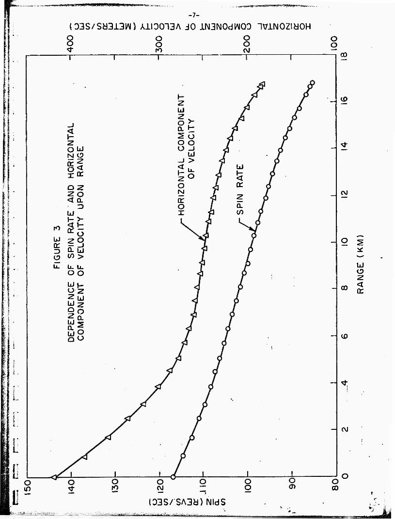
Figure 3 illustrates the deperJence of the horizontal velocity
component and the spin rate upon range. Both velocity and spin decrease
monotonically with range, and therefore, with time.
i / i
It is clear, therefore, that all the important parameters change
continuously with time. From this it is concluded that two types of
operation are possible.
A. Operate only during any portion of the trajectory in which
these time dependences uend to compensate for each other.
B. Measure independently these time de^p.ndent parameters and
telemeter the values to the receiving station. Employ a
computer to reconstruct the imagery from knowledge of the
parameter values and time dependent photosigna?.
Obviously it is much more simple to operate in mode A than mode B,
Accordingly, the thrust of this analysis will be to examine the ballistic
data in light of the scanning model to be developed, then ascertain
which, if any, portions of the trajectory allow for mode A operation.
If any portion does, then operation of the scanner during that portion
will be considered in detail.
2.0 OPTICAL CONFIGURATIONS
2.1 Description
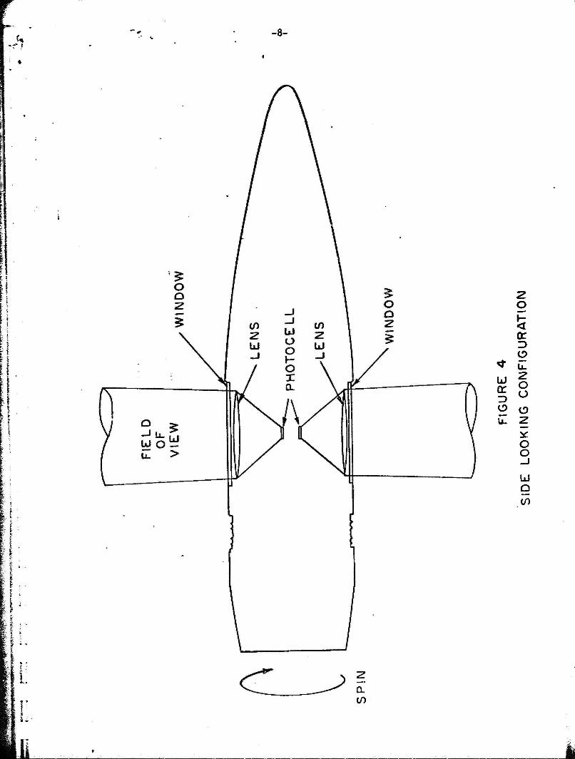
There are three optical configurations which are envisioned:
A. A "side looking" one in which the field of view is normal to
the axis of the shell, see Fig. 4. In this configuration the
optical system would be mounted, say, halfway back from the nose.
The round might be contained within a sabot discarded after
I^Sa^ *" _-.* —^^ ~* ~,^* *i~*~X* i~ L^~™ ^ _^ ^ ^-_^ ^~~ —^
.! mmmmmmnmmmmtmii
-7-
03S/Sd313W) AiI00"13A JO ilNGNOdWQO IVlNOZldOH o o to -r
o o o o
00
u a: D
m
2
O 2 20 < QL • D U
S^ ^ö
ÜL U tn >
li. ll_
oo
Ü 2 Id O 2 U 0. U) Q
2 ÜJ 2 O QL
O o
o > / £H ^5 5o JT o o y^ O -J ji
u / -1 > ^j
H1- 2 0
o < 3 ^ N J tr f 1 2 o /. CL x fl cn
Ü)
CM
O
CD CC
co
CM
O O
O o CO
l03S/SA3id)NldS J» ^^
-• I
-8-
o
(E I? O
o o
o o
hi a
if)
ll
-9-
launch, to protect the optics while within the artillery tube.
Several optical systems would be arranged around the circumference.
If the required scan angle were sixty degrees, then six systems
would be employed. If a focal length greater than allowed by
the shell diameter were required, the optical axes of the six
systems could be arranged parallel to the shell axis, and plane
mirrors inclined at 45° to the axis would direct the field of
view normal to the shell axis.
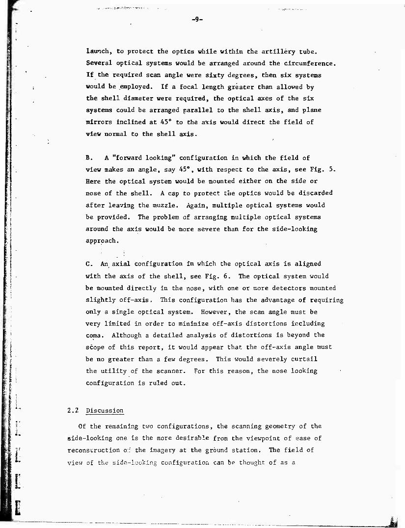
B. A "forward looking" configuration in which the field of
view makes an angle, say 45°, with respect to the axis, see Fig. 5.
Here the optical system would be mounted either on the side or
nose of the shell. A cap to protect tue optics would be discarded
after leaving the muzzle. Again, multiple optical systems would
be provided. The problem of arranging multiple optical systems
around the axis would be more severe than for the side-looking
approach.
C. An axial configuration in which the optical axis is aligned
with the axis of the shell, see Fig. 6, The optical system would
be mounted directly in the nose, with one or more detectors mounted
slightly off-axis, This configuration has the advantage of requiring
only a single optical system. However, the scan angle must be
very limited in order to minimize off-axis distortions including
coma. Although a detailed analysis of distortions is beyond the
scope of this report, it would appear that the off-axis angle must
be no greater than a few degrees. This would severely curtail
the utility of the scanner. For this reason, the nose looking
configuration is ruled out.
2,2 Discussion
Of the remaining two configurations, the scanning geometry of the
side-looking one is the more desirable from the viewpoint of ease of
reconsuruction o:: the imagery at the ground station. The field of
view of the side-looking configuration can be thought of as a
E
-10-
1
li
li in
in hi rr 3 O
2 O
3
LL.
2 O Ü
O z if o o _J
o <
IT O U.
.Ld

„ ■ - ..-.>,lV/Wm*'HW«'^!i'-'r
-11-
2 O
< CD Q:
u §
- 8 <
x
i-
> Q.
-12-
clrcular plane concentric with the shell, see Fig. 7. Cln reality, the
plane is very slightly wedge shaped in cross-section, the wedge angle
being the instantaneous angular field of view.) Regardless of the
orientation of the shell with respect to the. horizontal, the intersection
of this plane with the ground plane is a straight line. (It will be seen
In Section 3.1.3 that the width of the line varies with distance from the
center.)
■■ On the other hand, the field of view of the forward looking one is
a cone whose apex is along the centerline of the shell. (Here too, there
is a £ ^ght wedge-shape.) The intersection of this cone with the ground
plane is an ellipse, a straight line, or a parabola. Which of these
geometrical figures it is depends upon the instantaneous value of the angle
which the shell makes with respect to the horizontal, see Figs. 8 and 9,
Because the angle changes continuously during flight, the shapes of these
figures change with each scan during flight.
Reconstruction on the ground of the forward looking Imagery Is
difficult. The most direct way would be to employ a reflecting cone
whose half angle is the same as the angle which the optical system makes
with the shell axis. Radiation from a point light source whose Intensity
is modulated by the electrical signal telemetered from the shell would be
reflected from the cone to fall upon a sheet of photographic film placed
horizontally below the cone. The angle which the cone makes with respect
to the film plane would be changed with time in a manner coincident with
that which the shell In flight makes with respect to the ground plane.
In this analogue method of imagery reconstruction, the path of the radiation
from the lamp to the film would be similar to the path from the earth plane
to the detector. Thus the modulated radiation reflected to the film by
the cone would trace out ellipses and parabolas similar to those scanned
by the shell on the earth.
3.0 PERFORMANCE CALCULATIONS
Calculations of the system performance can be divided into those
relating to geometrical considerations and those relating to photometric
ccc3icer;itic;-.^. Ir. the. inalysis which follows, it will be asf.ur^.ed that
the side-looking configuration is employed. The previous discussion
iitowaM^iaMMjiyaiw^wfift^wat^ gSja^gjg^aaäsaiBaj • --f t~ — ji mms >jw<««'«nt»»n.<i

mmmmmmmg^HtK^^SIKmH^mmK-!-
-13-
L
L E E
u.
o UJ LJ >
2 O h- < o: D
2 O ? u o lu 2 h- 2 < Ü O _J LJ O CL in
o X LJ 2 f- 1 \~
o o <
UJ
2
a: 1 < UJ
u g 2 </) _J u.
o N
^ 1
" ~
UJ >
\.J u. o o _J UJ
^S\S^ u. u ^^y^ 2
^^S-^i LL < ^^ O _l r^ CL ) 2 / o r
•
SE
CT
I E
AR
!
tt ^_ ' i^t
? 5

-14-
Z g
a: O u. z o o CD z o o _J
o a: < 5
"Is ÜJ
5 u. o o o UJ
> u. o o _i UJ
z o F
_1 o CD < a: < DL
I
hi Z < -J CL
X H
UJ <
J

.»»j^iWS-BW^W«»«»^«»-«^----.-,- -.-.,,_
-15-
1?
4 ■-.
kl Q:
O
z o
b.
O O o
8
o: e O -J
w -
u
O _j O üJ
ÜJ U.
ü- O a O X
u < cn u Sx H I-
li
«iMIJ.iii.ii.i.l-,^i | i ...W.-^.^.

-16-
has shown that the geometry of the scan pattern projected upon the
ground for the forward looking configuration is an ellipse or parabola
whose shape changes continuously with time during flight, whereas that
for the side-looking configuration is a straight line, independent of
time. Furthermore, the only portion of the trajectory in which it might
be desirable to look at a forward angle along the flight path rather than
normal to it, would be near impact. Yet it will be seen that mode A
operation, in which the time dependences of the parameters entering into
j the scanning equation tend to compensate, is possible only during the
middle portion of the trajectory. Because the forward looking configura-
tion is the more complex, yet has no readily ascertainable advantages,
analysis of it will be left to some future date if warranted.
3.1 Geometrical Considerations
3.1.1 Time Independent Contiguous Mapping
Analysis of the scanner geometry is similar to that of an airborne (2)
mapper, discussed by Holter and Wolfe. The shell rotates at a rate
r revolutions pier sec. Let n be the number of optical systems, arranged
every 360/n degrees around the axis. At the focal point of each lens
let there be a linear array of i detectors, the axis of the array
paralleling the shell axis. Let there be i electronic
systems operating in parallel. At any instant these electronic systems
are individually connected to the detectors in a given array. This
array is the one whose optical system is looking downward, rotating
j through an angle of 360/n about the vertical. The output of each of
I i the i electronic systems is multiplexed to the telemetry transmitter.'
I . As the shell rotates, the electronic systems are simultaneously switched f » I i from array to array as each array rotates through the identified angle.
| A timing signal for the switching, provided by a horizon sensor or t. % f j some other means, is also telemetered to ground.
I | i Assume each detector element is square, having side length p.
| ' If the focal length of the lens is f, the instantaneous angular field
I , of view ß is given by
L
P
(i)
ismäB&tMiiiSk^äiiZiüäiiZs ääSasÄsSäasÄi

-17-
For the system to produce useful imagery, 0 should be no greater than 1
ndlliradian, with 0.1 milliradian preferred.
With each rotation of the shell, i parallel scan lines are swept^out
on the ground perpendicular to the shell axis. Since the shell axis is
tangent to the trajectory, the field of view intercepts the ground at an
angle to the normal which equals the angle 6^ of the shell axis with respect
to the horizontal. During the initial portion of the trajectory in which
the shell is rising toward apogee, the nose up condition causes the optical
system to scan the earth plane at a point, termed the track, ahead of the
point directly below the shell, i.e., the range. At apogee, when the shell
axis is horizontal, the track and range coincide. Beyond apogee, the nose down
attitude causes the track to trail the range. The relationship between
track and range is given by
x = x + h tan9 • (2) o D
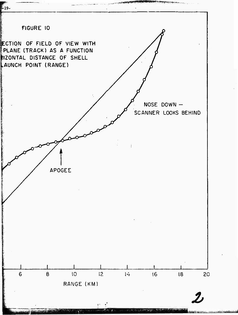
where x is the track and x is the range. Values of track as a function
of range for the assumed trajectory are listed in Table 2 and plotted in Fig. 10.
Because track and range coincide at launch and also at impact, yet
differ in between except at apogee, the track and range velocities must differ.
The range velocity is simply the horizontal component of the shell velocity.
The track velocity V can be computed from the time derivative of the track
position. Thus
2 deD VT ^ VH + VV Can eD + h SeC 9D "IT ; (3)
where V and V,, are the horizontal and vertical coniDonents of the shell n v
velocity.

._, ,^^f^^miy^^^fi^^^^'T^. ^:
-18-
A
00 o>u-irHu^omiHoo<r-*avoOi-tr-, <rin<r>-t(nQO^o»a--<rrost(smoco
Ovor^irioooocMcr>i~-vor-<-vOf^<Nr-i(T..^(SrHa3cMOHr^inooiN<trH «sr^voaioo-a-vor^r-vDm-jr-a-^a-roinr^CTvoc^ncsov-a-voirieMeM-* nmr<.00o\OOOOOOOOOOOOOiHrHHrHOO<J<00<t<SOO
O O O O O H rH rHHHrHHOOOOO
(SJ333W)
ft
a» «a,i~.ineNOCMtnCTicsr~-vnCT>OvOP--r^eMvOcv)N3-cor>.r--vocSi-icsovo
OfooocviovsfrH-jroooocnoocorHO^oovom^rHinooocNO-Tt-iesio VO0000<TCriCN<r)Cnmc«1CSCM(N(Ni-(CMfn-*invOv£)\O^tCM00r-lr-li-ICNl
ooooooooooodooooooooooooooooo
o\>a-oo-a-coincncMi-tr-ivO(T>oooor^cMCNir-»or->vo<d-r»oocsoo<r)i-i r^in'^iricr>\o-*i--ioiNONroinvoinev4oOt-Ho>roov\o<rcrsi-ioocvjr^>3-
, .' xooHOi^csivxs^HcNicsirofn^rofncvicNOCTi^orn^for^ooiricsica (Sia^Biy OrHro<i-iriinvDvOvOP>'r^r-i^r-.r^.p^p^t~-i^>r^vOvovoinu-i<3-rr)csi-400
m oooodooodoooooooooooooooooooo
H < Z H W < Z Q H Ü s PÄ o w Pi
ft, p o w
H CO •< w J
o m
r^o\r^si-I-(or~.oOHoo><^<Nsrt^rH<yiOoooi^ oom-a-r-voroaioocsoutcoooc^oo-a-Oi-iOfoo
fl vO ,0 ul vD O O O H.ro <t -S- O f"
J^
00000000000000000000000000000
vOt-»CMC»"IU-|i-IO>'-t""IP-t-( ai<J<y>iAsj-oooi-iLno>vo r^oOrHoovomnrocMiHiH cnr-ii-ioooooooo
8OO0O0000000 00000000000
00 (N 00 ON H ir, ON O <!• VO r-- O c-i PI in r- m co -H rH vO CM CM r- fO IO H r-- sf CM <r •<r r- iH •<r i-(
CO 0 O o> ON CM -* 0\ n ON 00 vO o^ vO m 0 00 m H rH rH 0 O tH r-i i-( CM r^ CO -j- m r- O m ro 0 O O O 0 O O O O O O 0 0 0 O rH CM in CM O O O 0 0 O O O O O 0 0 0 O O 0 0 CO O O O 0 O O O O O O 0 0 0 O O 0 0 0
00000000000000000000000000000
L
1.
(SJ[333>1) .oooNinoo-sj-r^-str^nvcincM^-ooonoo-^-tMoovoinracMcM-d-or^oovD D
FHr^r^rOiHe^-^-srincMcocvirHr-ir^vDrHOooNaNONi-i-j-ONC^iinmoooN Oco<^noo^nooo•^OOt-.ocMCM^o^^o•<rc^I-^(^l1-lONr-coa^•<tcMfM r^iHroo^(ooroco>H~3-'X)r»ONO'HCMn'nr^aNfnr~.cNr~»d-cMtHcM-*r^ t-ifn<tinvßvor~r-»cooocooooooNONONaNONONONOOr-i'HcM<vi-<rinsDvo
tHHrHi-li-li-l,HtHi-lT-i
[ li
(SJ33SW)
(spuooBg) aurfi
O «0 <«■ h- • < • •
O ITI «f O eo o o co r- <3-
<-! t^ rr\ & a < I » t f • •
« c^ p «NJ o ^-
-H o m "^ r- r^ IM n f^ ^ kA iA >0
ncöec>fMiAr^ino>in<r«f©(?c r T\ o to ^0 • • ,,.». »
C.-'aDOlfiinONeo — coOiArArNj^c^ O«\Jtf>0> 00'COC,-0^",-JOt^<"CNfM^N
QQ—i^rsirsjriP'i^criA'-A'O'ONO c »T o o -< f^ o r~ o co c* 0s
0<M"*«OC30fNJ^OSC<sJ-J->OeOON rocoofM«? sOcoofN.'>.'"<oorf>
c>f0^-oe:O(^if\f^0--'^N0ctoNvnr-c^'-<f2^
■^f'iii^^-tfriwi^^Bi^TyriMiir 1 afei^atigifcaaSaiaaaaa -1 hiii^-nr-niiB urn i-aniiiiBlf«!*

18 -ig-
le 11
I I ■
14
12
lOh
< o:
I i
FIGURE 10
INTERSECTION OF FIELD OF VIEW WITH EARTH PLANE (TRACK) AS A FUNCTION OF HORIZONTAL DISTANCE OF SHELL FROM LAUNCH POINT (RANGE)
NOSE UP - SCANNER LOOKS
AHEAD
0 12
RANiGE (KM)
■jifcäaädte Ijii^afeaa^iaa ajj^ja^aufea LL
i-w- - p_ , ^_
FIGURE 10
ECTION OF FIELD OF VIEW WITH //
iPLANE (TRACK) AS A FUNCTION y' P llZONTAL DISTANCE OF SHELL / 1 ^AUNCH
■■
[
POINT (RANGE) /I I / NOSE DOWN -
)'■■
/>
/ SCANNER LOOKS BEHIND
c^"
^
■;
APOGEE
[
>--
•
1 1 1 1 1 1 1 8 10 12
RANGE (KM)
14 16 18 20
2> t^M^^mMiim^^äsmA

-20-
The number of lines scanned per revolution is given by nJ!,, and the
number of lines scanned per second is given by n£r. Assume that the
scanning action must be contiguous, so that the lines are neither under-
lapped nor overlapped. Then the horizontal distance traveled by the field
of view per second must equal the total width of the lines on the ground
per second. The width w of each line upon the ground is given by r o
Thus
w = ßh sec 6^. o u
VT = ßhn£r sec OJJ;
(4)
(5)
Rearranging gives
3n£ = vTcos eD
hr (6)
The left side of Eq. (6) contains parameters whose values cannot be
changed during flight. The instantaneous field of view ß, decermined by
the size of the detector and the focal length of the lens, the number of
optical systems, and the number of elements in the array are all predet'.nuined.
The right hand side contains ballistic parameters whose values are constantly
changing during flight. The right hand side can only equal the left hand side
at more than one instant of time if the time dependences of V , h, r, and 9
compensate each other in the ratio.
The ratio contained in the right hand side of Eq. (6), calculated from
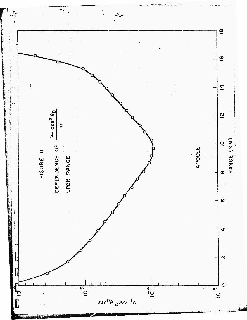
the ballistic data of Table 1, is listed in Table 2 and plotted a^ a function
of range in Fig. 11.
[ teaaüteaaüMM^a »wktiiagaaaiiiia^ a&&iai*.-kJ'ÄÄfe^i£M
-21-
11
IxJ LJ u UJ
CC 2 2 3 kl < O Q Q: U. 2
UJ 2 LL o U Ü. O D
Id ÜJ
o Q. <
to
J L
jy/Q0 ssoo J-A
GO
<D
CVJ
o 2 » *: *-' u o 2 <
00 or
tf>
CVJ

-22-
The ratio changes continuously during flight, rirst decreasing, then
Increasing past apogee. Only near apogee is it relatively independent of
range. The same conclusion is reached if the forward looking configuration
rather than the side looking one is employed, since the only change is to
increase the aspect angle 9 by a fixed amount.
It is thus clear that for the assumed trajectory the requirement for
time independent contiguous mapping cannot be met over an appreciable portion
of the trajectory. There is, however, a portion near apogee of cpproximately
1 kilometer length in which the requirement is essentially met, i.e., in
which the function plotted in Fig. 11 is nearly constant with range and track.
Thus the spinning round scanner can be employed over the assumed trajectory
by firing it such that the target of interest is below it at apogee. With
flatter trajectories it would seem that the useable portion of the trajectory
near apogee would be greater than 1 kilometer.
Consider now the magnitude of the system parameters. Figure 11 shows
that in the useable range near apogee the rat'lo on the right hand side of -4
Eq. (6) is approximately 1 x 10 . Experience dictates that a desirable
value of ß is of the order of 0.1 milliradian. Thus the n£ product-should
be unity, which can only be achieved through having n = 1 and Ä, = 1. In
other words, contiguous mapping can be achieved by having one detector
and one optical system. In practice, however, four optical systems, each
with one detector, would be a better choice, each responsible for a 90°
sector. Although this would lead to fourfold overlap in the imagery, this
should not be a serious problem. Indeed overlap can sometimes be employed
to increase the signal-to-noise ratio.
It is necessary to verify that the diffraction limit is not exceeded.
This is given by
ßD = 1,22X/D; (7)
«"i ^y&f"' s^*"";^;.'""' ■
-23-
«here X Is the wavelength of the radiation and D is the diameter of the
optics. Since the system is designed to operate in the visible portion -4
of the spectrum, X is approximately 5 x 10 cm. D must be much less than
the diameter of the 203mm round, so assume D to be 8cm. Then
ßD = 8 x 10 -6
radians.
Thus the system envisioned is more than an order of magnitude away from the
diffraction limit, which is certainly sufficient.
The detector side length is given by Eq. (1). Assuming an f/2 -3
optical system, then f - 16cm and p - 1.6 x 10 cm. Although preparing
a detector element whose side length is 16ym is difficult, it is within
the state of the art wher photolithographic methods are employed.
3.1.2 Dwell Time
Contiguous mapping is not the only constraint upon the system parameters.
It is also necessary that the scanner dwell on each resolution element a
time of at least kT, where k is a small number, say two, and T is the detector
time constant. The dwell time is given by the reciprocal of the number
of elements scanned per second, i.e., by (Zirr/P) . Thus
2T7r > kT; (8)
or
r < 2TTkT*
(9)
The ratio on the right of Eq, (9) involves the time independent
system parameters B and T, whereas r on the left changes with time during
flight. Since r decrease^ raonotonically with time, the inequality is
preserved throughout the flight if it is obeyed at launch.
Because the detector time constant has not yet been determined, the
inequality can be employed to set an upper limit to it. The value of 6 has
yä^^^aiMä^i^^j^iiäUiäiääuääim^älälu^äAätätsti^ääa^iii^^i iyaüBMaaiaaMi
I -24-
.-4 been determined to be 1 x 10" radians. Assume k = 2. Table 1 shows that r
at launch is 117 rev/sec (735 rad/sec). Then the inequality shows that
—8 T < 6.7 x 10 sec.
The maximum allowable value of T is therefore 67 nsec.
Ä»
3.1.3 Ground Resolution
A parameter of obvious interest is the ground resolution. At a given
altitude and aspect angle, the intersection of the instantaneous field of
view with the ground plane determines the ground resolution. As developed
in Eq. (4), the width w of each line in the direction of the flight path 0 2 and along the flight path depends upon sec 9 . The length m of each
resolution element in the direction perpendicular to the flight path along
the path is given by
m = 3hsec6_.. o D
(10)
To either side of the flight path, both w and m increase. From
Fig. 12 it can be seen that
2 2 2 w = w sec'6 " 3h sec 9„sec di; o Y D Y' (11)
and
n = m seed) = ßhsec9_sec(j); o D (12)
where ()) is the scan angle to either side of the normal,
value of n = 4 then $ = 45°.
Assuming the
L
Figure 13 illustrates the ground resolution as a function of range
for the assumed trajectory. The values of w and m have been computed
from Eqs. (4) and (10) using the data from Table 1, and the value of -4 3 * 1 x 10 previously determined. The values of w and m were determined
from Eqs. (11) and (12), using also the data of Table 1 and assuming -4 ß = 1 x 10 . Furthermore, the value of <}) = 45° has been assumed, so that
the w and tn values represent the resolution at the extrerv.e end of each
scanning line for a scanner having four optical systems, i.e., for n = A.

.^*%^^^^a^'<^«S^- -,:■ :■■■
■■■§ "-'* -25-
I
CL
Ui o:
UJ 5 o u o
u.
z <
z < o en
D o o z ÜJ OL
u CL
X
X o u.
is
L ggwanc-^^SS!

.^Ä«J^3*W*5»
-26-
_ O ^
isy3i3m Nounios^a QNnodo

a- ■^^^^^■^^f^^m^^^^^^^^flf^^^^^-'^
-27-
This is also consistent with the previous conclusions. Values of w , w,
m , and m can be found in Table 2. o
Figure 13 shows that the ground resolution below the shell along the
flight path is no poorer than about 0.54 meters in the direction of flight
(w ) and about 0.52 meters perpendicular to the direction of flight (m ).
These maximum values of resolution are attained near apogee and decrease
i slowly on either side of apogee. Furthermore, the maximum (poorest)
resolution at the extreme edges of the scan, i.e., for (j) = 45°, is approxi-
mately 1.08 meters in the direction of flight and 0.74 meters perpendicular
to the flight path.
Since the time independent contiguous mapping requirement is only achieved
near apogee, the appropriate ground resolution values are those near apogee,
which is the poorest case. Neverthelsss, the values quoted above compare
favorably with those obtainable from airborne reconnaissance imagery. They
are certainly adequate for targets such as vehicles, roads, buildings,and
groups of individuals.
3.2 Photometric Considerations
L
L [ L L
The previous section addressed the geometrical requirements relating
to contiguous mapping. The signal-to-noise voltage ratio and minimum
detectable contrast are the subjects of the present section. It is assumed
that the spin stabilized round is fired during a clear sunny day. The
terrain is assumed to be a flat Lambertian (perfectly diffuse) reflector
characterized by an average reflectivity p which is wavelength independent
over the spectral- interval to which the photocell responds. Point-to-point
variations in the reflectance which characterize the imagery are given by
Ap. The slgnal-to-noise voltage ratio for a given average reflectivity will
be determined in terms of the solar irradiance, photocell properties, and
optical system. The minimum detectable contrast, i.e., the normalized
minimum detectable change in reflectivity, will be determined. Measured
properties of silicon photocells will be introduced into the performance
equations to determine numerical values of the sigr.al-to-nolse voltage
ratio and threshold contrast.
iHiiMiia iiJ»^^.a»M.M...,»MI»»i..fl.*.,rf,n W>W,.

PIMnMMMWLUJWHM
-28-
I
3.2.1 Properties of Silicon Photocells
The spinning round scanner requires a low cost photocell. The dwell
—time-analysis indicated a very fast response was needed. The obvious
choice is a silicon (Si) photodiode. The properties of Si photodiodes
are reviewed below. These data have been compiled from that supplied (3)
by various manufacturers plus measurements reported by Naval Weapons (4)
-Center, Corona.
(5) * The photocell is characterized by its spectral detectivity, D,,
its solar detectivity, D (T ),and its response time, T. The spectral
detectivity is the output signal-to-noise voltage ratio measured in a
1 Hz bandwidth at a given center frequency in response to 1 watt of
monochromatic radiant power of a given wavelength. The solar detectivity
is the output signal-to-noise voltage ratio measured in a 1 Hz bandwidth
at a given center frequency in response to 1 watt of solar radiation.
The response time is defined in several ways; one is that point on the
modulation frequency response characteristic at which the signal voltage
has fallen to 0.71 of its value in the low frequency plateau.
A typical spectral response is illustrated in Fig. 14. The value of * 12 1/2
D. at the spectral peak, at 0.9ym is 2 x 10 cm Hz /watt. Also
illustrated is the spectral distribution of sunlight. From these two (6) *, *
curves, the conversion factor from D, (0.9lim) to D (T ) is found to be
3.3. Thus the value of D*(TS) is 6 x 1011cm Hz1/2/watt.
I I
The response time of a Si photodiode can be limited by either the
time for photoexcited hole-electron pairs to transit the depletion region
of the junction or by the ILC product, where R is the load resistance
and C is the junction plus package capacitance. With the very small
junction areas required for the intended application, the junction and
package capacitance would be sufficiently small so that for reasonable
makes of R the frequency response would be limited by the electron-hole
transit time. In general, this would be of the order of 10 nsec, certainly
meeting the 67 nsec requirement determined earlier.
»',a»Td- ,Pv. .„ .«j jitfjmtf.figjiifl

r1 -29-
b. O '
l*J U o tno 2 ^ -i
OP
j
\
^^
RE
LA
TIV
E
RES
Ri
Y^
S
ILIC
ON
P
HO
TO
2 O O _l
u. o
O
a. X
<
A
\ / ^ o:
u LJ
—i ^y ^^^ LJ 2 X \ S^ CC O o 1-
^k ^r^ 13 Q. <o U- ^w ^r O (O O ^Q U. Ul •• ""-i ^r ^^ Q: UJ u
^ ^r ^w o o * i fc J ^V _J o <
^^ ^V^ < ^»^ u: X ^V cc o K X ^^^ h- o D —
2U X \w o fe
^
2 .x i ' ^s^ *** Q. X H
P •" / (/) Q. <
Sfe ( —i
-sy ^^^^
3a: ' ^-~>_ "-- «j Ö 3
v* I </) cn
■—
i I I I I I 1 1 1 . L 1 ^j I I
en d
00 Ö d ö
in d d d d
SiiNn 3Aiivi3a
ro
CVJ
d
CD d
d
to d
in d
d
ro od
if) 2 O
o 2 Ul _J Ul > <
fc^:-^**^^eÄÄ£^ßäiiftSK«ias5iMte^ a^üfeayMgü^iiB&iaü - JS^iii

-30-
3.2.2 Signal-to-Nolse Ratio and Minimum Detectable Contrast
Consider the geometry Illustrated in Fig. 15. Sunlight falling upon
the terrain with an irradiance (radiant power per unit area) of H is
reflected by the surface in a Lambertian mannerj described by a cosine
distribution about the normal. The photocell at the focal point of
the optical system within the spinning round views the terrain through 2
• solid angle B at an angle of incidence (L along the path of length
R. Assume that at a given instant the area A on the terrain intercepted 2
by the solid angle 0 is on the flight path, rather than to one side of
it. Then
m cos6 (13)
The radiant intensity J, i.e., the radiant power per unit solid
angle centered about the angle 6 , is given by
J •= pHA„cos9n
(14)
where the factor TT rather than 2Tr in the denominator arises from the
Lambertian reflecting nature of the terrain. The radiant power P
intercepted by the lens having diameter D is then given by
jTrD2T "4R2-
(15)
where T is the transmission of the atmosphere over the path length
R averaged over the spsctral interval of interest.
Combining Eqs. (13) - (15) results in
P •=
2 2 pH3 D T
(16)
I I
Thus the radiant power falling on the photocell is proportional to 2
the terrain Irradiance and reflectance, the solid angle 6 through
which the photocell views the terrain, the area of the lens, and the
atmospheric transmittance. It is independent of the aspect angle
6 • the cosine distribution of the Lambertian reflector just cancels D the cosine dependence of the reflecting surface area upon 9 .
■rssKsasasfflBffiäBBBiffiiaaiasyMi nrni-if"-'——

X I
-31-
lO 1 —
u (T
m
< 2 <
or U 5
o r Q.
a: e >
u o UJ
11,
li
I k

-32-
An alternative expression for P is obtained by introducing F, the
f/number of the lens,
x D (17)
Combining this with the expression for 3, Eq. (1), allows Eq. (16) to be
rewritten as
p - PHp T 2
4F
2 where p is ehe area of the detecting element of the photocell.
(18)
The signal-to-noise voltage ratio in the output from the photocell
is given by
PD*(TS)
N 1 pB 1/2 (19)
where B is the bandwidth in which the signal-to-noise is measured.
(The noise voltage is proportional to the square root of the bandwidth).
The bandwidth is determined at its upper limit by tha dwell time T.
Its lower limit will be of the order of 100 Hz, to minimize the contribu-
tion from 1/f power law noise. Thus, for all intents and purposes,
B = 2T\X '
(20)
For T= 67 nanoseconds, B = 2.38MHz. Combining Eqs, (lfcy,(19), and
(20) results in
I vs \ pH32D2TD*(Ts)
\ VN 4pB 1/2
(21)
1
L
Equation (21). describes the signal-to-noise voltage ratio In the
photocell output in response to sunlight reflected fror, terrain having
an average reflectivity p. This expression does not provide for contrast
in the scene. In reality, the imagery is reconstructed from small
variations Ap in the reflectance. Without these, the scene would be
uniformly bright, devoid of detail.

-33-
Thus, a figure of merit of particular interest is the minimura
detectable contrast, C ., , defined as that minimum contrast in the min'
scene which gives rise to a signal just equal to the noise within the
bandwidth B. Since contrast is defined as
Ap (22)
i
1
C is determined by solving Eq. (23) for that value of Ap required
to give rise to a signal-to-noise voltage ratio of unity, then dividing
by the average reflectivity p. Thus
C . = mxn
4pB 1/2
pHß2D2TD*(Ts) (23)
which is just the reciprocal of the signal-to-noise voltage ratio.
[
I I I I r
i
Note the Eqs. (21) and (23) do not contain explicitely any trajectory
parameters. The signal-to-noise voltage ratio and the minimum detectable
contrast are Independent of range , altitude, and aspect angle, except
insofar as the atmospheric transmittance T depends slowly upon range.
It can be seen that the path length R and angle 9 both cancel in the
expression for the radiant power P falling on the photocell, Eq. (16).
The theoretical values of the signal-to-noise voltage ratio and
minimum detectable contrast can now be determined. The irradiance of 2
sunlight outside the atmosphere (solar constant) is 0.14 watts/cm .
Because of atmospheric absorption over the wavelength interval of interest,
the irradiance H at the surface of the earth on a cloudless day will be 2
approximately 0.09 watts/cm . The reflectance p of terrain varies
widely over the earth, but a representative value in the spectral interval
of interest is 0.1. A representative value for the lens diameter D is
8 cm. It has already been shown that a reasonable choice for ß is 1.0 x 10 -3
radians, and that p = 1.6 x 10 cm. The transmission of the atmosphere
Is assumed to vary only slowly with path length. Over the spectral interval
and path lengths of interest its value is estimated at 0.8. The value of
* 11 1/2 solar detectivity D (T ) is 6 s 10 cm Hz /watt. The value of the
bandwidth B is assumed to be 2.38 MHz.
-A
HüidiMiülililiit ^•-^■'^^ • -^ - *^.L*. '„.^^.,-~*~^.:--::*,^>;^'^™. imfflfff'ifffihüiftlti ^Ä^^^a^Ü-ääl^bSiiT^

-34-
Insertlng these values into Eq. (21), the signal-to-noise voltage
ratio is found to be
= 280. N
Similarly, the minimum detectable contrast is
C J = 0.00357. min
I
I
I I I I I I I I I
Thus, with values of the parameters consistent with the problem, the
predicted signal-to-noise voltage ratio is 280, and the minimum detectable
contrast is 0.36%. In other words, a reflectivity change of 0.36% of the
average reflectivity of 10%, or an absolute reflectivity change of 0.036%,
is detectable.
The values of signal-to-noise voltage ratio and minimum detectable
contrast permit high quality imagery under clear sky daylight operational
conditions. Operation under cloudy conditions, in which the irradiance
is reduced by one order of magnitude, is even possible, since the signal-
to-noise voltage ratio and minimum detectable contrast depend linearly
upon the Irradiance. That is to say, under an overcast sky, the signal-
to-noise voltage ratio would be 28, and the minimum detectable contrast
would be 0.0357. Of course, the cloud layer must not be between the scanner
and the earth, so the cloud ceiling must be higher than the apogee, since
time independent contiguous mapping is possible only near apogee for the
trajectory under consideration.
ü-s^äi^^^k^M^^iw^AÜä^ 'ti iivitiiiitiir -^-^ äiäi M ■ ■-li.y^.^Ä^^^^.U^^ii.i-;:^. ...- r,:..:-;.^^.^.j,.*.,.. -u.^.'....,^---^ ■^^■^-aAa.

-35-
4.0 DISCUSSION AND SUMMARY
This report constitutes an initial examination of the co^ept of
employing an expendable spin stabilized artillery round containing a
* simple optical system and telemetry equipment to obtain reconnaissance
i imagery. The analysis considers the geometric and photometric require-
ments, including time independent, contiguous mapping, signal to noise ratio,
and minimum detectable contrast. Equations are derived having general
I i applicability. In order to obtain numerical values of the appropriate system
performance parameters, data for a 203inm round fired due north from the
i equator at a 45° elevation with a zone seven charge have been employed.
There is nothing unique about this trajectory; it was simply one provided
I to illustrate the calculations. Indeed, it appears that a lower elevation
with a flatter trajectory would have been a better choice.
Three configurations for the scanner were initially considered, an
axial one, a forward looking one, and a side looking one. The axial one
was ruled out because of its limited field of view. The forward looking
one was not considered in detail because it introduces excess complexity.
That is to say, the intersection of the field of view with the earth plane
is a series of parabolas and ellipses whose parameters change continuously
during flight.
The side looking configuration has been examined in detail. The
requirement for time Independent contiguous mapping, summarized by Eq.(6),
is applicable to all trajectories. Introducing the assumed trajectory
data. Table 1, it is found that the contiguous mapping requirement is
satisfied during an interval of about 1 kilometer near apogee. Actually,
the requirement is not really satisfied, since the scanning lines will
overlap. However, the ground based imagery reconstruction system can
accommodate the excess information provided by overlap, whereas it cannot
of course supply the missing information had underlap been the problem.
The ground resolution has been examined both along the track and
perpendicular to it. Equations (4), (10), (11), and (12) expressing it
are generally applicable to all trajectories. By introducing the assumed
trajectory data, the resolution at apogee was found to be
iMiilMM'^'^lihiilfffiWiKMa^iii^iiifeltrfc^

1
I 1
I I 1 1
L
-36-
roughly 0.5 meters square along the track, increasing to about 0.7 x 1.1
meters at the maximum distance perpendicular to the crack (45° off-axis).
These values should certainly be adequate for imagery of vehicles, road,
buildings, and groups of personnel. It may "be possible to exploit the
overlap to obtain imagery of even higher resolution.
The analysis also showed that the optical system could be very
simple, four lenses arranged at 90° intervals about the shell circumference,
each with a single silicon photocell at the focal point.
The photometric requirements have been examined in detail. Equations
(21) and (23)-, generally applicable, describe the signal-to-noise voltage
ratio and the minimuir: detectable optical contrast. The trajectory does
not enter explicitely into the photometric considerations since the path
length and aspect angle both cancel in the expression for the optical
power reaching the photocell.•
By inserting values of solar irradiance appropriate to a clear day,
the signal-to-noise voltage ratio and minimum detectable contrast have
been numerically evaluated. These values assure excellent performance
under sunlit conditions. It appears that even with an overcast sky,
the performance would be very good. Of course, the optical system cannot
"see"through clouds; the round would have to be fired below the cloud
layer.
In summary, then, it appears from this initial examination that the
spinning round concept is feasible, or at least it has not been shown
to be not feasible. The photometric requirements can be met during
daylight operation, even beneath clouds. The time independent contiguous mapping
requirement for the assumed trajectory can be met over a distance of
about one kilometer near apogee. Presumably the requirement can be met
over an even greater distance for a flatter trajectory. In operation, the
shell would be fired such that the targets of interest lay below the shell
at apogee. The ground resolution so obtained would certainly be adequate
for many targets of interest.

-37-
5.0 RECOMMENDATIONS
Because this initial study has shown the concept to be a promising
one, further studies are warranted. Among these are the following:
Other Trajectories
Examine other trajectories to see whether the contiguous mapping
requirement can be met over a distance greater than 1 kilometer.
Rather than employing numerical data in the form given in Table 1,
combine the trajectory equations with the contiguous mapping and
ground resolution equations, then solve directly to obtain plots
similar to'Figs. 11 and 13.
Synch Signal
A synch signal is required to trigger each scan line in the
ground based receiver. Some device such as an on-board horizon
scanner is;needed. Determine the synch signal requirements and examine
possible techniques for meeting them.
Telemetry System
The telemetry system has been ignored. Explore the Initial
configuration of the on-board transmitter and ground based receiver.
Imagery Reconstruction Equipment
Explore the requirements and configuration of the ground based
equipment employed for imagery reconstruction.
Shock & Vibration
From sources of information such as Project HARP examine whether
the electronic and optical systems can withstand the firing shock.
L Lab Experiments
Simulate the scanner by breadboarding the optical system, mounting
iiiiitiiiaiWi ilrffif*-^' ^in ^^■^-a

rfi
ftl
il:
L
L 1
-38-
It on a turntable to provide the scanning action, providing a controlled
optical input representing sunlit terrain, and examining the electrical
output from the photocell.
Initial On-Board System Layout
Consider how to configure the optical and electrical equipment
for various rounds such as the 155mm, 175inm, and 203inm ones.
System Cost
Obtain a rough cost estimate of the expendable round and the
ground based equipment.
-Applications
Determine the military use of the system, given its performance
and limitations, for the 155mm, 175mm, and 203inm rounds.
Alternative Approach
Examine the feasibility of the mode B approach wherein the time
dependent parameters including altitude, aspect angle, velocity, and
spin rate are continuously monitored and their values telemetereJ to
the ground based receiver to be used in the imagery reconstruction
equipment. Determine whether the additional complexity and cost is
a valid tradeoff for being able to obtain useful imagery over the
entire trajectory.

I -38-
?i it on a turntable to provide the scanning action, providing a controlled
optical input representing sunlit terrain, and examining the electrical
output from the photocell.
Initial On-Board System Layout
Consider how to configure the optical and electrical equipment
for various rounds such as the 155mm, 175mm, and 203mm ones.
System Cost
Obtain a rough cost estimate of the expendable round and the
ground based equipment.
-Applications
Determine the military use of the system, given its performance
and .limitations, for the 155mm, 175nim, and 203inm rounds.
Alternative Approach
Examine the feasibility of the mode B approach wherein the time
dependent parameters including altitude, aspect angle, velocity, and
spin rate are continuously monitored and their values telemetereJ to
the ground based receiver to be used in the Imagery reconstruction
equipment. Determine whether the additional complexity and cost is
a valid tradeoff for being able to obtain useful imagery over the
entire trajectory.
L ,li
ik^i-'s^&irt^a.fii^^ « afeaaiai^äjfc^a^ga^ ii ifttiiiiifäi^BffahiB^^thirrriiiiiriiifTi iiiiriivi vam IHHIJ^**-^^-*^ -v:ma-> ■itifraii "Tfjj^gaaüafeiaite''"--■--■ ^^J*!.*