UNCLASSIFIED AD NUMBER - Defense Technical … · UNCLASSIFIED AD NUMBER ADBOO0731 ... natural...
81
UNCLASSIFIED AD NUMBER ADBOO0731 NEW LIMITATION CHANGE TO Approved for public release, distribution unlimited FROM Distribution authorized to U.S. Gov't. agencies only; Test and Evaluation; OCT 1974. Other requests shall be referred to Air Force Materials Laboratory, Attn: MBE, Wright-Patterson AFB, OH 45433. AUTHORITY AFWAL notice, 3 Nov 1983 THIS PAGE IS UNCLASSIFIED
Transcript of UNCLASSIFIED AD NUMBER - Defense Technical … · UNCLASSIFIED AD NUMBER ADBOO0731 ... natural...

UNCLASSIFIED
AD NUMBER
ADBOO0731
NEW LIMITATION CHANGE
TOApproved for public release, distributionunlimited
FROMDistribution authorized to U.S. Gov't.agencies only; Test and Evaluation; OCT1974. Other requests shall be referred toAir Force Materials Laboratory, Attn: MBE,Wright-Patterson AFB, OH 45433.
AUTHORITY
AFWAL notice, 3 Nov 1983
THIS PAGE IS UNCLASSIFIED

TI41S REPORT HAS BEEN DELIMITED
AND CLEARED FOR PU$L'C RELEASE
UNDER DOD DIRECTIVE 5200.20GANDNO RESTRICTIONS ARE IMPOSED UPON
ITS USE AND DISCLOSURE,
DISTRIBUTIONJ STATEMENT A
APPROVED FOR PUBLIC RELEAS
DISTRIBUTION UNLIMITED#

AFML-TR-74-107
EXPLORATORY DEVELOPMENT OF NEWt`0 AAWD IMPROVED SELF-SEALING MATERIALSo FOR FUEL LINES0
NOR TIIR OP CORPORATIONAIRCRAFT DIVISION
IA WTHORNE, CALIFORNIA 90250
OCTOBER 1974
FINAL REPORT COVERING PERIOD 26 FEBRUARY 1973 - 15 MARCH 1974
Distribution limited to U.S.Govermnent agencies only; (test and evaluation)October 1974. Other requests for this document must be referred to AirForce Materials Laboratory, Nonmetallic Materials Division, Elastomers andCoatings Branch, AFML/MBE, Wright-Patterson Air Force Base, Ohio 45433.
0D'D C
AIR FORCE MATERIALS LABORATORY ' IfliAIR FORCE SYSTEMS COMMAND-U
WRIGHT--PATI'ERSON AIR FORCE BASE, OHIO 53R & U A ,

NOTICE
When Government drawings, specifications, or other data are usedfor any purpose other than in connection with a definitely relatedGovernment procurement operation, the United States Government therebyincurs no responsibility nor any obligation whatsoever; and the factthat the Government may have formulated, furnished, or in any waysupplied the said drawings, specifications, or other data, is not tobe regarded by implication or otherwise as in any manner licensing theholder or any other person or corporation, or conveying any rights orpermission to manufacture, use, or sell any patented invention thatmay in any way be related thereto.
Copies of this report should not be ieturned unless return isrequired by security considerations, contractual obligations, ornotice on a specific document.
This final report was submitted by the Northrop Corporation, Air-craft Division, Hawthorne, California, under USAF Contract F33615-73.C-50S6, Job Order No. 73400552, with the Air Force Materials Laboratory,Wright-Patterson Air Force Base, Ohio. Mr. T. L. Graham (MBE) was thelaboratory project monitor.
This technical report has been reviewed and is approved forpublication.
T. L. GRAHAMProject Monitor
FOR THE COMMANDER
ME ILL L. MIN~GES,CG ief~E1 tomers and Coatings BranchNonmetallic Materials Division
AIR FORCE/56780/16 December 1974- 100

-= t- --- - -
UNCLASSIFIEDSECURITY CLASSIIFICATION OF THIS PAGE (When Data Entered)-
i~i ' EPOT DCUMNTAi0NPAGE READ INSTRUCTIONSREPORT DOCUMENTA I iON BEFORE COMPLETING FORM
I. REPORT NUMBER 12. GOVT ACCESSION NO. 3. RECIPIENT'S'CATALOG NUMBER
AF.NL"TR- 74-1074. TITLE (and Subtitle) S. TYPE OF REPORT & PERIODCOVERED
EXPLORATORY DEVELOPMENT OF- NEW AND IMPROVED Fifidl ReportSELF-SEALING MATERIALS FOR FUEL LINES 26 Feb. 73. 15 Mar 74
6. PERFORMING ORG. REPORT "UMBER_ _ _ _ _ _ _NOR 7,4-63.
7. AUTHOR(s) 0. CONTRACT OR GRANT NUMBER(e)
R . M . H ei't • 7 -"F. Hill F33_615-73-C-5056
9. PERFORMING ORGANIZATION NAME AND ADDRESS o 10. PROGRAM ELEMENT, PROJECT, I ASKNorthrop Cdiporation', Aikcraft Division AREA& WORK-UNIT NUMBERS
3901 West Broadway Pzoj-ect No. 7340Hawthorne, California 90250 Task No. 734005
It. CONTROLLING OFFICE NAME AND ADDRESS 12. REPORT. DATE
Air Force Materials Laboratory June 1974Air Force Systems Command 13. NUMBER OF PAGES
- Wright-Patterson AFB, Ohio 45433 6714. MONITORING AGENCY NAME & ADDRESSrif differenl Irom CoQntrotllpg Office) IS. SECURITY CLASS. (of this report)
UNCLASSIFIEDISa. DECLASSIFICATION/DOWNGRADING
SCHEDULE
"16. DISTRIBUTION STATEMENT (of this Report)
Distr~ibution limited to U.S. Government agencies only (test and evaluation);October 1974. Other requests for this document must be referred to the AirForce Materials Laboratory, Nonmetallic Materials Division, Elastomers andCoatings Bran~ch, AFML/MBE, Wright-Patterson Air Force Base, Ohio 45433.
17. DISTRIUUTION STATEMENT (of the abstract entered In Block 20, If different from Report)
18. SUPPLEMENTARY NOTES
19. KEY WORDS (Continue on reverse side If neceessry and Identify by block number)
Damage Control SystemsSelf-Sealing SystemsProjectile (AP)Fuel LinesShock Waves
20. ABSTRACT (Continue cri reverse side If necessary and identify hy block number)New and improved self-sealing fuel line composites were developed under
this program. Fabric reinforced plastic and nonflowering integrated aluminumfoil, fabric reinforced laminated fuel line composites employing compressednatural rubber foam as the sealant were fabricated which successfully sealedwounds inflicted by .30 and .50 caliber projectiles. The weight of thesenew self-sealing fuel line composites ranged from 0.83 to 1.28 lbs,ft 2 . Astandard aluminum fuel line provided with a conventional self-sealing pro-tective cover capable of sealing wounds inflicted by .50 caliber projectilesDDFORM
D ,IAN 73 1473 EDITION OF I NOV 65 IS OBSOLETE UNCLASSIFIED'ICURITY CLASSIFICATION OF THIS PAGE (Ithen Data Entered)

SECURITYCLASSIFICATI6-4OF -'THIS PAGE(Wflen Data Entered) , ~
20O. ABSTRACT '(Continu6d)
nomnaly eigs 259 lb/f 2 . Rcr~jlts, of pressure -tests- derionstrat&J-
the f abric reinforced., plasttic fur. l~ine and certain fuel line compositebased on plieii of a~hiinafum foji-. i Iinforced 'with- plies-of bafitidt. -.iylcnfabric :t6, be. ca0pble-.of withsat;,ding -hydrauli:c pressure in exceab.;6f''240.POsi and kedistant to distr~libn under (29.5 inches of .Hg) vac~uum.Y he cmrse asefsl- i,)-concept-utiliLzing plies--of-ballisticnyloni for controlling dhataiag v-salso-investigated as a mneans ofprotecting standard aluminixz jFvel line tubing. Theslseig
, compressed' foam coipo'site ~ 3 aated for protecting a standard aluminulm- -fu~el line was found- to be b 4eý_tive- for sealing wounds- inflicted -by
30 ~ caliber projectiles but -s?. ved to be inadequate at th& 5~ai~K ~ - projectile ~threat level.
UNCLASSIFIEDSECUJRITY CLASSIFICATION OF THIS PAGE(Whon Date En~erod)

FOREWORD
This report was prepared by the Northrop Corporation, AircraftDivision, Hawthorne, California, under USAF Contract F33615-73-C-5056.The contract work -was performed under Projec. No. 7340,. "Nofimetallicand Composite Materials," Task No. 734005, "Elastomeric and ComplýiantMaterials." It was administered under the direction of the NonmetallicMaterials Division, Air Force Materials Laborhtory, Air Force SystemsCommand, Wright-Patterson, Air Force Base, Ohio, with Mt. T. L. Graham(MBE) as- the'Project Monitor.
Dr. R. M. Heitz served as the Principal Investigator on thisprogram. Other Northrop personnel who made -major contributions 41this research program were Dr. G. H. Bischoff, F. Hill, V. L. Johnson,and H. Miller.
The contractor's report number is NOR 74-63. This report coVerswork from 26 February I973,through 15 March 1974.
This report was submitted by authors 25 March 1974.

ABSTRACT
New and improved self-sealing fuel line composites were developedunder this program. Fabric reinforced plastic and nonflowering inte-grated aluminum foil, fabric reinforced laminated fuel line compositesemploying compressed natural rubber foam as the sealant were fabricated,which successfully sealed wounds inflicted by .30 and.50 caliber pro-jectiles. The weight of these new self-sealing fuel line compositesranged from 0.83 to 1.28 lbs./ft 2 . A standard aluminum fuel lineprovided with a conventional self-sealing protective cover capable ofsealing wounds inflicted by .50 caliber projectiles nominally weighs2.59 lbs./ft 2 . Results of p.-ssure tests demonstrated the fabricreinforced plastic fuel line and certain fuel line composite based onplies of aluminum foil reinforced with plies of ballistic nylon fabricto be capable of withstanding hydraulic pressure in excess of 240 psiand resistant to distortion under (29.5 inches of Hg) vacuum. Thecompressed foam self-sealing concept utilizing plies of ballistic nylonfor controlling damage was also investigated as a means of protectingstandard aluminum fuel line tubing. The self-sealing compressed foamcomposite evaluated for protecting a standard aluminum fuel line wasfound to be effective for sealing wounds inflicted by .30 caliberprojectiles but proved to be inadequate at the .50 caliber projectilethreat level.
iv

TABLE OF CONTENTS
Section Page
INTRODUCTION ....... ............ ................. I
II TECHNICAL DISCUSSION. . .... .............. 3
A. -DEVELOPMENT OF PROTECTION SYSTEMS-FOR PREVENTINGRUPTURING AND FLOWERING OF METALLIC. FUEL LINES . . .. 4
1. Fuel Line'Test Setup . ....... . . . . . . . 4
2. Ballistic Tests Performed with Unprotected andProtected (Damage Control System Only) MetalFuel Linen ................ .................... 4
3. Performance of a Metal Self-Sealing Fuel Line. . . 9
B. DEVELOPMENT OF NON-FLOWERING SEMI-METALLICFUEL LINES .......... ........................... 9
1. Preparation of Laminated Aluminum Foil FuelLines Unprotected and Protected (Non-Self-Sealing)and Ballistic Tests ................... 24
a. Fabrication Methods Used for the LaminatedMetal Fuel Lines ........ ............... 24
(I) Method for the Unprotected LaminatedMetal Fuel Lines .... .......... ... 24
(2) Method for the Protected Non-Self-Sealing Laminated Metal Fuel Lines. . . . 25
b. Ballistic Tests ...... ................ .... 25
c. Improvement of the Developed Protected Non-Self-Sealing Laminated Aluminum Foil FuelLines Concept ...... ................. .... 34
d, Structural Strength Increase of the LaminatedFuel Lines Unprotected and Protected (Non-Self-Sealing) ....... ................. 41
(I) Fabrication of the Unprote:ted ReinforcedLaminated Aluminum Fuel Lines andBallistic Test ..... .............. ... 41
V

CONTE&TS (Continued)
Section 'Page
II B. (2) Fabrication of the.Protected ReinforcedLamirated Aluminum Fuel Lines andBallistic Tests .............. 42
2. Preparatiotn-of Laminated Self-Sealing AluminumFoil Fuel Lines and Ballistic Tests; . ...... .... 43
C. DEVELOPMENT OF NON-FLOWERING PLASTIC FUEL LINES. . .. 50
1. Preparation of Plastic Fuel Lines. . ....... .... 50
a. Plastic Fuel Lines Fabrication Procedure . . . 50
b. Fabtication of Unprotected Plastic FuelLine: and B3allistic Tests .............. .... 50
c. Fabricaion of Protected Plastic Fuel Linesand Ballisti< Tests ..... ............. .... 53
D. DETERMINATION OF BURST AND COLLAPSE PRESSURES ONUNPROTECTED AND PROTECTED (NON-SELF-SEALING)LAMINATED AND PLASTIC FUEL LINES ... ........ ...... 60
i. Bur~t Pressure Test ..... ............ ...... 62
a. Burst Pressure Test Setup .......... ...... 62
b. Procedure of Test ....... ..... ....... 62
2. Collapse Pressure Test ....... .... ........ 62
a. Test Setup Used ........ ...... ........ 62
b. Procedure of Test ........ ..... ....... 62
E. HYDRAULIC RAM EFFECT . . .......................... 64
III SUMMARY AND CONCLUSIONS .... ......................... 65
IV RECOMMENDATIONS AND FUTURE WORK ...................... 67
vi

LIST OF ILLUSTRATIONS
Figure Page
1 FUEL LINE TEST SETUP....................
2 METAL FUEL LINE - LINE CONFIGURATION A ............... 6
3 METAL FUEL LINE WITH DAMAGE CONTROL SYSTEM -
FLEXIBLE LAMINATE - LINE: CONFIGURATION B ..... ......... 6
4 METAL FUEL LINE WITH DAMAGE CONTROL SYSTEM -
FLEXIBLE LAMINATE - LINE CONFIGURATION C ... .......... 7
5 METAL FUEL LINE WITH DAMAGE CONTROL SYSTEM -
FLEXIBLE LAMINATES AND FOAM - LINE CONFIGURATION D . . . . 7
6 METAL FUEL LINE WITH DAMAGE CONTROL SYSTEM -
FLEXIBLE LAMINATE - LINE CONFIGURATION E . . . ..... 8
7 PERFORATED METAL FUEL LINE WITH PROTECTIVE SYSTEM -
FLEXIBLE LAMINATE - LINE CONFIGURATION F ... .......... 8
8 PERFORATED METAL FUEL LINE WITH PROTECTIVE SYSTEM -
FLEXIBLE LAMINATES AND FOAM - LINE CONFIGURATION G . ..... 10
9 IMPACTS IN PROTECTED AND UNPROTECTED LINES (35 LB.LINE PRESSURE) - LINE ENTRY SIDE .... ............. ... 15
t0 IMPACTS IN PROTECTED AND UNPROTECTED LINES (35 LB.LINE PRESSURE) - LINE EXIT SIDE .... .......... . . . . . 16
11 METAL FUEL LINE - BULLET HIT FITTING - ENTRY SIDE, .... 17
12 METAL FUEL LINE - BULLET HIT FITTING - EXIT SIDE . . . . . 18
13 METAL FUEL LINE PROTECTED WITH 2-PLY FLEXIBLE LAMINATE . . 19
14 METAL FUEL LINE PROTECTED WITH FLEXIBLE LAMINATEAND FOAM ................ . . . . . . . . . 20
15 METAL SELF-SEALING FUEL LINE - LINE CONFIGURATION H. . . . 21
16 TEST RESULTS OF THE METAL SELF-SEALING FUEL LINE . . . . . 22
17 NON-FLOWERING SEMI-METhLLIC FUEL LINE CONCEPT -
LINE CONFIGURATION J ......... ................... ... 23
18 LAMINATED ALUMINUM FOIL FUEL LINE - LINE CONFIGURATION I . 23
19 LAMINATED ALUMINUM FOIL FUEL LINE - LINE CONFIGURATION K . 26
vii

ILLUSTRATIONS (Conitinued)
Figure ,Page
S20 NON-FLOWERING SEMI-METALLIC FUEL LINE CONCEPTLINE CONFIGURATIAN L ............ .................... 26
21 LAMINATED ALUMINUM FOIL FUEL LINE - LINE CONFIGURATION M * 27
22 NON-FLOWERING SEMIýMETALLIC FUEL LINE CONCEPT -
LINE CONFIGURATION N .... . ..................... .. 27
23 LAMINATED ALUMINUM FOIL FUEL LINES - LINE CONFIGURATION 0. . 28
24 NON-FLOWERING SEMI-METALLIC FUEL LINE CONCEPT -
LINE CONFIGURATION P ....... . .......... ........... .. 28
25 Al UNPROTECTED LINE - A2 PROTECTED LINE -ENTRY SIDE .... 30
26 Al UNPROTECTED LINE - A2 PROTECTED LINE - EXIT SIDE, ... 30
27 BI UNPROTECTED LINE - B2 PROTECTED LINE - ENTRY SIDE .... 31
28 BI UNPROTECTED LINE - B2 PROTECTED LINE - EXIT SIDE. . . . . 31
29 Cl UNPROTECTED LINE - C2 PROTECTED LINE - ENTRY SIDE . . . . 32
30 Cl UNPROTECTED LINE - C2 PROTECTED LINE - EXIT SIDE. . . . . 32
31 D1 UNPROTECTED LINE - D2 PROTECTED LINE - ENTRY SIDE . . . . 33
32 Dl UNPROTECTED LINE - D2 PROTECTED LINE - EXIT SIDE. . . . . 33
33 NON-FLOWERING SEMI-METALLIC FUEL LINE CONCEPT -LINE CONFIGURATION U. . . . . . . . . ........... 40
34 LAMINATED Al FOIL FUEL LINES (3 LAYERS OF .003-INCH5052-H38 Al, FM-123 ADHESIVE) PROTECTED AND UNPROTECTED. . . 44
35 NON-FLOWERING SEMI-METALLIC FUEL LINE SELF-SEALINGCONCEPT - LINE CONFIGURATION V-I .................... 45
36 NON-FLOWERING SEMI-METALLIC FUEL LINE SELF-SEALINGCONCEPT - LINE CONFIGURATION V-2 ..... .............. ... 46
37 NON-FLOWERIN% SEMI-METALLIC FULL LINE SELF-SEALINGCONCEPT - LINE CONFIGURATION W ....... ............... ... 47
36 NON-FLOWERING SEMI-METALLIC SELF-SEALING CONCEPT -LINE CONFIGURýTrION X ............. .................... ... 47
vii

ILLUSTRATIONS (Continued)
Figure Page
39 LINE CONFIGURATION V-I1 ....................... 48
40 LINE CONFIGURATION V-2......... ..... .. *-. .-... 48
41 LINE'CONFIGURATION W .... 49
42 LINE CONFIGURATION X ................ . ...... . .... 49
43 NON-FLOWERING PLASTIC FUEL LINE - LINE CONFIGURATION Y . 51
44 NON-FLOWERING PROTECTED PLASTIC FUEL LINE - LINECONFIGURATION Z. . ..................... 51
45 PROTECTED PLASTIC FUEL LINE (1-PLY FLEXIBLE LAMINATE) -
ENTRY- SIDE ................................. 56
46 PROTECTED PLASTIC FUEL LINE (I-PLY FLEXIBLE LAMINATE) -EXIT SIDE ............... .......................... . 56
47 NON-FLOWERING PROTECTED PLASTIC FUEL LINE - LINECONFIGURATION XY ............. ....................... 58
48 NON-FLOWERING SELF-SEALING PLASTIC FUEL LINE -LINE CONFIGURATION XZ .......... .................... . 58
49 LINE CONFIGURATION XZ ........ ................... ... 59
50 PROTECTED PLASTIC FUEL LINE (FLEXIBLE LAMINATE AND FONAe) -ENTRY SIDE . . . ...................... 61
51 PROTECTED PLASTIC FUEL LINE (FLEXIBLE LAMINATE AND FOAM) - "EXIT SIDE. ....................... . 61
52 BURST AND COLLAPSE PRESSURE TEST SETUP ....... .......... 63
ix

LIST OF TABLES
Table /Pg
IIMPACT TEST RESULTS ON UNPROTECTED AND PROTECTEDMETAL FUEL LiNES .............. .. .. .. .........
- IIIMPACT TEST RESULTS'ON 'UNPROTECttD AND PROT'ECTE*D'SEMI-METALLIC FUEL LINES........,. ., . 3
III IKPACT TEST RESULTS ON UNPROTEC;TEDAND PROTEC-TEDPLASTIC FUEL'LINES ....... .. ...................... '54

SECTION I
INTRODUCTION
Limited war operations have demonstrated that a considerable hazard stillexists from small arms and anti-aircraft ground fire. Penetrati-n of an air-
craft fuel system by a 20mm or smaller projectile can produce fuel leaksleading to fuel starvation, fires, explosions, or catastrophic destiact.ion ofan aircraft. In the past, the bulk of the effort in the area of self-sealingfuel lines has been devoted to the develornent of self-sealing protectivecovers (e.g., self-sealing fuel cell materials) for metallic fuel lines whicitend to flower or petal when punctured by a projectile. Although some successhas been realiz•' at the .50 caliber level threat, the conventional protectivecover approach ,as not proved entirely satisfactory. Because of this flower-ing tendency metallic fuel lines, more sealant mutt be applied than wouldbe required if petalling did not occur; consequently, excessive weight andvolume peralties have resulted. The development of self-sealing fuel lineswhich do not flower when punctured appears to be a method of improving seal-ing efficiency and minimizing weight and volume penalties.
The objective of this investigation was the deielopment of a non-flowering- self-sealing fuel line material for protecting fuel lines against .50 and .60
caliber AP projectiles penetrating at normal incidence, and .30 caliber APprojectiles penetrating at normal incidence and in the fully tumbled condition.It was proposed, first, to develop a non-flowering fuel line. This was doneby developing metallic, semi-metallic, and plastic composite fuel lines thatare non-flowering and by reinforcing fuel lines with a damage-control systemto make them non-flowering. The non-flowering fuel lines developeO were madeself-sealing by application of existing self-sealing bladder materials andof existing integral tank self-sealing materials to the inside, outside$ orboth sides of the fuel line. If necessary, new self-sealing systems were tobe developed. Efficient sealing against a fuel line pressure of 35 psi wasrequired and was achieved.
A hydraulic ram study of the impact of projectiles on fuel lines underpressure was made to determine if any unusual phenomena occur that requirespecial consideration in the development of non-flowering and self-sealingfuel lines. High-speed films were taken to observe the projectile behaviorwhile penetrating the fuel lines. Very high local pre ,sure phenomena wereobserved.
In the work performed for preventing rupturing and flowering of metallicfuel lines, flexible ballistic nylon laminate and/or a foam was used to reducethe damage to pinhole size holes which were sealable by using systems likea precompressed fuel sensitive foam self-sealing concept. Non-floweringsemi-metallic fuel lines were made of laminated aluminum foil. These weremade effective against .30 and .50 caliber AP projectiles by protecting withflexible laminates bonded on the inside and outside of the line. Non-floweringplastic fuel lines were fabricated by using ballistic nylon cloth, polysulfidesealant, foam, at.d epoxy resin. Pinhole size holes were experienced whenthese lines were impacted by .30 caliber AP projczti'^-. Self-sealing wasperformed against .30 and .50 caliber AP projectiles by using fuel sensitiveand precompressed fnam.

Burst and collapse pressure 'tests were conducted with the laminated foilfue~l lines and the plastic fuel lines,_both unprotected' and protected.
All the work items mentioned above- are reviewed in Section II of this-report.
2
'(7'

SECTION II
TECHNICAL DISCUSSION
The state-of-the-art technique for protecting conventional aluminum fuellines is to wraD the ling.5 with a salfrsea1ing-material similar to.-that usee•- in self-sealing fuel cells or bladders. This techni-qu often is less. than
satisfactory because the fuel lire flowers when a fragment,,or,ýrojectilepasses 'through it, and the f lowerin-g, ofk the nietbl f uel, 1'in _make~s.,ýn_openhole in the self-sealing marý2rial that does hot seal. FuzthaemorZ-the highfuel line pressure in tne line (:35 psi),keeps the wound- open and preventsthe self-sealing system- from acting.
Under Air Force contracts, Northrop has developed techniques to reduceor eliminate cataatrophic rupturing of aircraft integral fuel tank wa'lls whenimpacted by AP and API projectiles. These damage control systems prevent theflowering of the integral tank wall and allow the self-sealing systems tooperate efficiently, One of the most successful self-sealing systems developedto date is the system using a precompressed and fuel sensitive foam for seal-ing in combination with a flexible ballistic nylon laminate as the damagecontrol system. The ballistic nylon damage control system is essentially ahigh-tear-strength flexible laminate whirh prevents flowering of the integralmetal tank wall.
The development of self-sealing systems for fuel lines presents two moredrastic problems than the similar development, for integral fuel tanks, First,because the fuel lines are so small in diameter, flowering caused by projectilepassage becomes a major problem. In a large integral tank wall, one footsquare or Ilarger, the wall motion can relicve th- effect of the flowering;the exit wall moves outward with the projectile and the hydraulic ram pressures,and this motion relieves the tendency to flower. However, the small diameter,2- to 3-inch fuel line is essentially rigid to the impact of a projectile orfragment. Flowering is drastic and is not rel~eved by the motion of the metalfuel line wall. Second, the self-sealing must be more rapid and of highefstrength for the fuel line than for an integral fuel tank. The fuel lineoperates at a fuel line pressure of about 35 psi. This pressure producesliquid flow that tends to keep any fragment or projectile wound open, andprevents self-sealing materials from closing the wound. The self-sealingsystems must be able to resist the effect of the 35 psi in the fuel line.
In this work, Northrop has considered the exploratory development of anon-flowering self-sealing fuel line material for protecting fuel linesagainst .50 and .60 caliber AP projectiles penetrating at normal incidence,and .30 caliber AP projectiles penetrating in a tumbled condition. Initially,non-flowering fuel lines were developed. This was done either by the develop-ment o. a metal, a semi-metallic, or a plastic composite fuel line that isnon-flowering, or by reinforcing a metal, a semi-metallic, or a plastic fuelline with a damage control system to make it non-flowering. The. the non-flowering f,,pl line developed was made self-sealing by application ' existingintegral fuel tank self-sealing materials to the inside, outside, or bf Isides of the line. The approach to self-sealing against high pressure was
.1

-r 7 4 7F. 7 . .77:7"'
three-fold: first, we used a damage control system that will hold the self-sealing material in the wound area; secofnd, we used a pressurized system with
a natural tendency to flow into the wound; and third, we used the fuel linepressure to help push the sealing material into the wound area.
A hydraulic ram effect study of the impact of pr6jectiles 6n fuel linesunder pressure was made to determine if any unusual phenomena are occurrin>hat require special consideration in the development of non-flowering andself-sealing fuel lines.
A. DEVELOPMENT'OF PROTECTION SYSTEMS FOR PREVENTING RUPTURING AND FLOWERING
OF METALLIC FUEL LINES
Si. Fuel Line Test SetuD
Initially in the program, a fuel line test setup was fabricated. Thiswas used in all fuel line ballistic tests. As shown in the diagram (Figure 1),this setup can be used in tests where either water or fuel is used as thecirculating fluid. When fuel is used, the recycling system of the setup isused. The recycling of the fuel is performed with the help of a special fuelpump. This pump is explosion-proof and is set at 35 psig and 5 to 10 G.P.M.This will maintain the fuel under pressure while flowing through the fuelline before, during, and after impact. When using water as the circulatingfluid, the fuel recycling system is shut off and the water system is used asshown in the diagram. The whole setup is mounted in ouch a way that it canbe dismantled in a few minutes and transported in a compact state.
2. Ballistic Tests Performed with Unprotected and Protected (Damage ControlSystem Only) Metal Fuel Lines
A series of tests was conducted where existing metal fuel lines, eitherunprotected or protected, were tested against .30 caliber AP and .50 caliberAP. A comparison was made of the degree of damage occurring with either theunprotected or protected metal fuel lines. All the lines had an I.D. of 2ýinches, a thickness of .0zd-inch, a length of 3 feet, and were 6061-T4 alumi-num alloy (see Figure 2). Each line tested was mounted to the fuel line testsetup (see Figure 1) with the water or fuel flowing at a 35 psi pressure in-side the fuel line.
In the case of the protected metal fuel lines, the protection systemused was either a 2-ply or 3-ply fleMible ballistic nylon laminate and/orfoam bonded on the outside of the line using 898 sealant (see configurationsin Figures 3, 4, and 5). The systems were cured at 100'F for 4 hours. Theflexible laminates were prefabricated using 2 or 3 layers of ballistic nyloncloth impregnated with 898 polysulfide sealant. A laminate using PRD-49cloth was also used (see Figure 6). The laminates were used as damage controlsystems only and were not intended to self-seal the wounds. The immediateobjective was to prevent or minimize rupturing or flowering of the metalline, and to determine whether the protective system would keep the damagelow enough so that it could be sealed by a self-sealing system when impactedby small-arms projectiles (.30 and .50 caliber AP and .60 caliber ball).
4

FLOW CONTROLHAND VALVE
C4 1-4
>, M
~Z4 FUEL
K , U)Z LINE
PRESSURE GAGE0-60 PSI
FUEL PRESSURE HAND VALVE
REGULATOR FOR DUMPIN
LHAND VALVE TO BE
E OF TUND F WE
S~WATER PRESSURE•. -- REGULATOR SET5AT 35 PSI
• WATER
50 GAL. TANK
51FIGURE . FUEL LINE TEST SETUP
tR
5EUAO E
IIw,

.028-Inch Thick 6061-T4 Al
FUEL
FIGURE 2. METAL FUEL LINE - LINE CONFIGURATION A
2-Ply Flexible Laminate (Ballistic Nylon ClothImpregnated with 898 Sealant)
Wall of Existing Metal Fuel Line(.028-inch 6061-T4 Al)
FUEL
FIGURE 3. METAL FUEL LINE WITH DAMAGE CONTROL SYSTEM -FLEXIBLE LAMINATE - LINE CONFIGURATION B
6

j- 3Plýr -Fle'xibre Laminate ('BaTis tic Iyon)
Wall of- EistingMetal Fuel Line
(.028-!Inch 6061b-T4 Al)
FUEL
FIGURE 4. ýMETAL FUEL LINE WITH DAMAGE CONTROL SYSTEM-FLEXIBLE LAMINATE - LINE CONFIGURAPTON C
1-Ply Flexible Laminates (Ballistic Nyloni)
1/4-Inch-Thick Foam (Neoprene, Slight Precizmpression)
t Wall. of Existing Metal Fuel Line
(.028-Inch 6061-T4. Al)
Z/ L I-4j/ 4 -1
FUEL
FIGURE 5. ,METAL FUEL LINE WITH DAMAGE CONTROL SYSTEM-FLEXIBLE LAMINATES AND FOAM -LINE CONFIG-URATION D
7

-7-
- 2-P:Ly Flexibte Laminate (PRD-49-181 Cloth ImpregnatedWith 898 Sealant)
Wall of Existing Metal Fuel 1Line(.028-;Inch 606l-T4 Al)
FUEL
"FIGURE 6. METAL FUEL LINE WITH DAMAGE CONTROL SYSTEM -FLEXIBLE LAMINATE - LINE CONFIGURATION E
2-Ply Flexible or Semiflexible Laminate (Ballistic Nylon)
Perforated Wall of Existing Metal Fuel Line(.028-Inch 6061-T4 Al)
f//I/I////'4 .~.Q//''//// if, 777
FUEL
FIGURE 7. PERFORATED METAL FUEL LINE WITH PROTECTIVE SYSTEM -FLEXIBLE LAMINATE - LINE CONFIGURATION F
8

In addition to the existing metal fuel lines, either unprotected orprotected, perforated metal fuel lines with protection systems (see Figures 7and 8) were fabricated. The perforation lowerpd the weight of the line and
minimized the flowering. The perforated metal line contained. 3/8-inch diameter
holes spaced approximately 3/16-inch apart. The procedure used in the fabri-
cation of these perforated lines was (1) perforate a metal sheet (.028-inch
thick, 606i-T4 Al) to the desired diameter holes, and (2) roll the pertorated
sheet into a 2½-inch I.D. line. The bonding agent used-was either 898 poly-
sulfide sealant or FM-123-2 (modified epoxy).
in this series of tetts, .30 and .fO caliber AP projectiles impacted
the lines either in a 90' ox 450 angle of incidence (0* yaw) or in a tumbled
condition. The results of iripagts in the unprotected and protected linesare given in Table I and corresponding figures.
The line configurations denoted by a letter of the alphabet in each
sketch of each figure are reflected by the same letter in Table I.
3. Performance of a Metal Self-Sealing Fuel Line
The sketch shown in Figure 15 describes the self-sealing concept whichwas evaluated. This system was used earlier (see Section A2 of this write-up)
Sas a protection system to prevent flowering of the fuel line wall. With aslight modification, it can be used as a protection system and a self-sealingsystem. Incorporating a higher degree of precompression of the foam and afuel sensitive foam (such as natural rubber foam), the system gave an effectivefast seal against .30 caliber AP projectiles.
As shown in Figure 15, the flexible laminates and foam (¾-inch thicknatural rubber foam) were bonded together to the metal line by using 898polysulfide sealant. The completed self-sealing line was mounted to thefuel line test setup. The fuel (JP-4) recycling system of the setup wasused and the line pressure was set at 35 psi. Upon impact, no loss of fuelwas noticed and the line pre3sure dropped to 34 psi (as witnessed by a high-speed film) for a very short time before returning to the initial fuel flowingpressure of 35 psi. The degree of damage suffered by the metal seif-sealingfuel line is shown in Figure 16. At the entry side the metal wall showedheavy inward flowering. This did not affecL the self-sealing system materialsinasmuch as sealing was obtained. In a further test, an identical self-sealingfuel line was fabricated and tested, this time against a .50 caliber AP pro-jectile. The damage at the entry and exit sides was minor, but due to theheavy flowering of the metal wall at the exit side, a complete seal was notobtained. For more details on damage, see results in Table I.
B. DEVELOPMENT OF NON-FLOWERING SEMI-METALLIC FUEL LINES
In the development of semi-metallic fuel lines, a series of conceptswas investigated. One of these concepts in particular, because of its pro-mising aspects, was thoroughly evaluated during this program. This was theconcept of a combination of laminated aluminum foil and flexible or semi-tlexible laminates. A sketch of this concept configuration is given inFigure 17.
9

A I1-Ply Flexible or Semiflexible Laminate (Ballistic Nylon) I
/ 1/4-Inch-Thick Foam (Neopr'ene 'Typ'e)
Perforated Wall of Existing Metal_Fuel Line ('.028-Inch 606i-T4 Al)
.. . ., .
,• •:~... .. .. .......... . .:, ...... ::=./ ......
FUEL
FIGURE 8. PERFORATED METAL FUEL LINE WITH PROTECTIVE SYSTEM -
FLEXIBLE LAMINATES AND FOAM - LINE CONFIGURATION G
'1
L
K-
C,'
4'

LL,
x C', :0
ci0 1 0: I -
_k0 53 V 0 w ' 1
0 -.c cC- cix.' ~ '~*i ~ ~ '
= 0, 0I V -0 . 00 >.'I , 5
cc o a0 , .9 A. 'I in1J0 '* l..6. ~10-- ,0 x.0
61,000. -"0.0 00 0.* * ~~ 0 ;c i.0 ý0' - O.cc a c c 'c cli 0.~ i0 ci0 ~ ..wo.A000 x00~~* 0
~U0.t 0 U0
00 01 c i00 L
(n 0.InIn*5
14 w' In o -
gL --
*' 0
00
6.6 0 U0 .o .u 9c 0o u
-- ~~ 0C I a.~ au 0 0
~~.. ~ I1 0 0 . , 0 cec0A0 0 Wc 0 4bo. 0 a 0 00 A,
0 4i
00 * C 0 .0w ~ c 0C~i-c00" 00 V~.*
v 0.00 0 0 ZO x
S0.
o 0 0U00,
0 m 1.
%, n~ a c 0-. 40 -~ -1 d a 0410 0a
~~00 N 411 - I I a~s~ - I>. x~ C -
.. ? b..g u C14~ D;1 1 ~ 4 0N 1 1 O .l1i.,4!9 - o, "o40 0 1 .)'o 1 C : - 2- .0 - A4 J, dlO f.1.~. 1 4~ N 4 . 0 - 410..C0 W XC- obN1X *N.£a.
A1104 ýw1 &4 wO02 r*0~~ 410o V~0~
000'0 ' 0 0 - -Nl , -: N0 ,. .
IA~~ rAI AI
10 0A 14 41Z ox
0u 4 ?1 L''~.1 4 .C Dm 6-O 10 *.x 4 11 m- 26 E 6c
- w 2 IV , N804 6 11C X 1.00 o c wCN1N41 am c
G 0- 2.o-.- 4.- .0C Id q=.e A w.> C
41N c 1.1 1 .o1
00 0 0C0I'~ 1141141 40 00 In6.14 1.' C- O 00 01.C.- .1
C 041)- 04 . 04100.000..- 004. 041- ;; 0. 0
.- !a 4. !
0 .0 0 .0 w0 4 c I
a, ..4 0 "0 C -1 -0a~
z
01
0 NA IAIA4Az
inC I ~40 C2
0 0 0 0 0z) 0 a
z z-
WI
I-.)
0. to

Q, -0 -~0 a41-I V V.- aO0 0W- .
AA41 0( 14 VOA 1.1 OC Q0 0S0 . 001 (V U4141~~~ -V 410 0 .0
0m 41 g.1 C401.~ 4 14 41ca,4A W0 01' Q
410 to rU 41 aC -o -a 0
.0A -Ax l0 .14 .4E ' 13' 41.0 - 0 12A
CL DI '4
-3 00eN 0 "S "0 t
0l .4. cl d :.a a~ 0 w 4Q V V
3 11-4- O - - W-
l0g P. 4 0 ; 9* 1141 MO -C410u0 00 0 1 0 a.! 0 r4 .1 0 0 o u, :c40
-C E!r J - "O 1- WF-C
aw"0 No 0j01N 100 u 0 00 0P
-~0 :-1w 0 al o 0 .00o
C'0. 0.1- 0apt)0
V 040 a4 o0 a ~ '0
00
.N1
el -n in
`0 10 qq N 0I
01 0 0000InI
In S 13

14,
x34 c. s -~
go: ~ C 4,: 0a lo. a -
~44-1 - 4V T3 -l-O. *.~ *0- -w0~
oiý.430,,-I. O~ 1;--
or)~
W-, -04 4 G
3 414

VI)
A-
a:
A4A
aw

cn
,dh
A4
mgPIT
16)

5. 3. 2-'
I
FIGURE 11. METAL FUEL LINE - BULLET HIT FITTING - ENTRY SIDE
17

S-L 3-72-I
FIGURE 12. METAL FUEL LINE - BULLET HIT FITTING - EXIT SIDE
18

i;;
Entry Side
Exit Side
FIGURE 13. METAL FUEL LINE PROTECTED WITH2-PLY FLEXIBLE LAMINATE
19

Entry Side
Exit Side
FIGURE 14. METAL FUEL LINE PROTECTED WITHFLEXIBLE LAMINATE AND FOAM
20

1-ýPly 'Flexible or Serni-ftexble ldiminat:(allis tic ',Nylon
1/4-Ihdh-Thick Foam- Preicoffioresised (Natural Rubber)
Fuel Line Metal: Walt.028-inch 60661-T,4, At),
/ // -FUEL
FIGU.. .. . .. .. .. .15 META SEFSAIGFULLN IECOFGRTO
a * * ' * . .21

Entry Side
Exit Side
FIGURE 16. TEST RESULTS OF THE METAL SELF-SEALINGFUEL LINE
22

1-Ply Flexible ox, SemiTflexib'le-Lamihate, (BallliiUc -Nylon),
Laminated,.Aluminum Foil (7 .Layers of -,.003-Inch5052~-H138 AL),
f j~~~Z ZZZ2L. L/ // Z_-
FUEL
FIGURE 17. NON-FLOWERING SEMI-METALLITC FUEL 'LINE "CONCEPT' -
LINE CONFIGURATION J
S -J
Laminated Al Foil Fuel Line (7 Layers of .003-Inch5052-H38 Al)
FUEL
FIGURE 18. LAMINATED ALUMINUM FOIL FUEL LINE - LINE CONFIGURATION I
23

~- ---------------
1. Preparation of Laminated Aluminum Foil. FuelLiniesUniprotected andProtected (Non:Self-Sealing) and Ballistic Tests
Eight laminated metal fuel lines, either protected or unprotected, werefabricated and ballisticaliy cested against .30 caliber AP projectiles. Themetals used were as follows:
.a. 5052;H38 - .003-inch thick, (7 layers)b. 1100-0 - .004-inch thick (5 layers),c. 5052-H38 - .004-inch thick (5 layers)d. 1100-0 - .002-inch thick (10 layers)
The total thickness of the laminated metal fuel line walls is approximately.030-inch. The length of the lines is 25 inches and the I.D. is 2½ inches.The bonding agent used to bond the thin metal sheets is 898 polysulfide sealant.With each metal type and chickness described above, a protected and unprotectedlaminated metal fuel line was prepared. The protected fuel lines contain a1-ply flexible ballistic nyion laminate on the outside and inside of the lineas shown in the sketch of the concept (Figure 17).
a. Fabrication Methods Used for the Laminated Metal Fuel Lines
(i) Method for the Unprotected Laminated Metal Fuel Lines
(a) A 32-inch long aluminum pipe having an O.D. of 2½ inchesand a wall thickness of 5/16-inch is used as a mold.
(b) In the first step, the mold is wrapped with a layer of-non-porous Teflon impregnated glass cloth to act as amold releasing agent.
(c) For each laminated metal fuel line to be fabricated, thecorresponding metal sheet is cut to a length to give theexact number of layers when finally rolled onto the pipemold.
(d) The cut metal sheet is then layed out on a table and
a thin layer of polysulfide 898 sealant is spread evenlyon the surface of the sheet. The mold (aluminum pipe)with the releasing agent is then placed at one end of the898 sealant covered metal sheet. The metal sheet is rolledcarefully and evenly around the pipe mold.
(e) After the rolling of the metal sheet is completed, a layerof non-porous Teflon impregnated glass cloth is placedaround -he laminated line. A plastic tape is then woundtightly and evenly around the line to apply pressure tomake good contact between each metal layer and obtain agood bond.
24

(f) Finally, the mold containirP,, metal sheet under pressureis placed in an oven at 180F for approximately 1½ hours tocure the polysulfide adhesive. Before removing the moldfrom the oven, the temperature inside the oven is loweredto room temperature. This cooling is necessary for self-sealing systems containing foam and is used as aonormalprecaution. Next, the plastic tape and mold release(Teflon cloth) wound around the line are removed and thecompleted unprotected line is separated from the mold.
(2) Method for the Protected Non-Self-Sealing Laminated Metal Fuel Lines
For this method, steps (a) and (b) are the same as in the abovemethod. In step (c) for this method, a layer-of ballisticnylon cloth is cut to size to give a I-ply laminate bondedinside the line. The cut ballistic-nyl6n cloth is layed out ona table and is impregnated with 898 sealant material. Theimpregnated nylon is then rolled carefully and evenly aroundthe mold to obtain a slight overlap where the two nylon clothedges meet. Step (d) is similar to step (c) in the above method.Step (e) is also similar to step (d) above, with the exceptionthat here the mold containing the I-ply wet laminate is placedat one end of the 898 sealant covered metal sheet. The metalis rolled carefully and evenly around the wet laminate coveredmold. Step (f) uses the same procedures as step (e) above,with the exception that before applying the non-porous Teflonimpregnated glass cloth arornd the laminated metal line, awet (898 impregnated sealant) ballistic nylon cloth layer isrolled around the laminated line to obtain a 1-ply flexiblelaminate bonded on the outside of the laminated metal line.At this point, the Teflon impregnated glass cloth is placedaround the wet laminate covered laminated line and the remainderof the fabrication method Is then similar to the above methodfor unprotected laminated metal fuel lines.
b. Ballistic Tests
In these tests, the fuel line test setup described above in Section Alwas used. For each test the protected or unprotected laminated metal fuel linewas mounted to the fuel line test setup. The water circulating system of thetest setup was used in the tests with the water flow pressure set at 35 psi.The gunfiring test was performed using the rifle with a l-turn-per-10-inchesrifling. The projectile (.30 caliber AP) hit the line in a 900 angle of in-cidence and 0* yaw. In the tests, the eight laminated metal fuel lines wereidentified as follows:
Al Unprotected Line (5052-H38 Al - .003-inch thick - 7 layers) - Figure 18A2 Protected Line (5052-H38 Al - .003-inch thick - 7 layers) - Figure 17Bl Unprotected Line (1100-0 Al - .004-inch thick - 5 layers) - Figure 19B2 Protected Line (1100-0 Al - .004-inch thick - 5 layers) - Figure 20Cl Unprotected Line (5052-H38 Al - .004-inch thick - 5 layers) - Figure 21C2 Protected Line (5052-H38 Al - .004-inch thick - 5 layers) - Figure 22Dl Unprotected Line (1100-0 Al - .002-inch thick - 10 layers) - Figure 23D2 Protected Line (1100-0 Al - .002-inch thick - 10 layers) - Figure 24
25

!I
Laminated AlA Foil (5 Layers of .004-Inch;1iO-0 , Al)
-m; N
FUEL
FIGURE 19. LAMIATED. ALUMINUM FOIL FUEL LINE - LINE CONFIGURATION K
1-Ply Flexible or Semiflexible Laminate (Ballistic Nylon)
/--Laminated Aluminum Foil ý5 Layers of
S.......... .L 004-1nch 1100-0 Al)
FUEL
FIGURE 20. NON-FLOWERING SEMI-METALLIC FUEL LINE CONCEPT -LiNE CONFIGURATION L
26

Laminated Ai, Foil. (5 iaers ot a004-Inch 5052-H38 Al'
FUEL
FIGURE 21. LAMINATED ALUMINUM FOIL FUEL LINE - LINE CONFIGURATION M
l-'Ply Flexible or Semiflexible Laminate (-Ballistic Nylon)
Laminated Aluminum Foil (5 Layers of,004-Inch 5052-H38 Al)
,~~~~~~~ 777 7777 2- i/~,
FUEL
FIGURE 22. NON-FLOWERING SEMI-METALUIC FUEL LINE CONCEPT -
LINE CONFIGURATION N
27
7W •

Laminated Al Foil (10 Layers of .002-Inch
f1OO6-o6 At~
FUEL
FIGURE 23. LAMINATED ALUMINUM FOIL FUEL LINES -LINE CONFIGURATION 0
1-Ply Flexible or Semiflexible Laminate (Ballistic Nylon)
i
Laminated Aluminum Foil] (10 Layers of.002-Inch 1100-0 Al)
' TV 1,4il /t i7 /L"J.7l//LZXT/Ltz•zz~z
FUEL
FIGURE 24. NON-FLOWERING SEMI-METALLIC FUEL LINE CONCEPT -
LINE CONFIGURATION P
28

STest Results
Al Line (Unprotected). At the entrance ' (see ýF'gure 25)a½-inch diameterhole occurr'ed-with'outward and inwrd f:.owqering., A 4inch long10ngitudinalcrack across the impact hole occurred. At :the exft K(see 'Figure 26) a 5/8-inch"diameter hole was made by the exiting projectile., Only 6utward, floweringoccurred and- a-3.-inch long loigiýtudinal crack across the hole occurred. Thewater flow pressure through. the line dropped from 35- psi d 9'w to 12 psi.
A2 Line "(Protected). In comparison- this pr6tected lI ne showed verypromising results. At the entry (Figure.,25), and exit (Figure,26,) pinholesize holes were noted. No appar.ent cracking or flowering Qf the laminatedmetal line o curred. The flexible .'aminate on the inside and- utside didnot show any tear damag&'. The water flow pressure dropped -from 35 psi downto 32 psi only.
Bl Line (UnUkrotected). In this test, catastrophic •ippuiri-g occurredat entry (Figubre 27) and exit (Figure 28) and particularl'y at the exit. Theline was almost cut in two and the water flow pressure dropped from 35 psidown to 0 ipsi.
B2 Line (Protected)., A drastic difference in damage, was observed inthis shot. The 1-ply flexible laminate on the inside and outside of the linekept the damage to pinhole size holes at entry (Figure 27) and exit (Figure28). Small cracking occurred in the laminated metal line underneath the
laminate. No flowering of the metal line was noted. The water flow pressuredropped from 35 psi down to 30 psi.
Cl Line (Unprotected). The pattern of damage occurring with this linewas very similar to the one with line Al (Figures 29 and 3Q). 'However, thedamage here was a little more extensive. The water flow pressure droppedfrom 35 psi down to 10 psi.
C2 Line (Protected). This line showed a pinhole size hole at the entrance(Figure 29)' with no cracking ef the laminated metal and no fiowering. At theexit (Figure 30) the'flexiblc laminate on the inside of the line showed a smallhole and n6 inward flowering of the laminated metal -line. The flexible laminateon the outside of the line showed a k-inch hole and outward flowering of themetal line. No cracking of the laminated line occurred. The water flowpressure dropped from 35 psi down to 22 psi.
D2 Line (Unprotected). The damage was still severe (Figures 31 and 32)but not as bhd as B! above, The water flow pressure dropped from 35 psi downto 9 psi.
D2 Line (Protected). The damage was reduced drastically. A pinholesize hole occurred at the antrance (Figure 31) with no cracking -or floweringof the laminated metal line. The exit (Figure 32) showed' a ¾-1nch hole inthe outside laminatc with some outward flowering and possible small cracksin the laminated metal line. The laminate on the inside of the line showeda pinhole size hole. The water flow pressure dropped from 35 psi down to25 psi.
29

FIGURE 25. Al UNPROTECTED LINE - A2 PF.OTECTED. LINE'ENTRY SIDE
FIGURE 26. Al U'NPROTECTED LINE -A2 PROTECTED LINE-EXIT SIDE
30

FIGURE 27. BI UNPROTECTED LINE -B2 PROTECTED LINEENTRY SIDE
FIGURE 28. Bi -iNPROTECTED LINE -B2 PROTECTED LINE-EXIT SIDE
31

SFIGURE 29. CI UNPROTECTED LINE -C2 PROTECTED LINE-MEW.- ENTRY SIDE
47-
- IIN
FIGURE 29. Cl. UNPROTECTED LINE -02 PROTECTED LINE-
EXIT SIDE
32

FIGURE 31. DI UNPROTECTED LINE - D2 PROTECTED LINE -
ENTRY SIDE
"I A,
FIGURE 32. Dl UNPROTECTED LINE - D2 PROTECTED LINE -
EXIT SIDE
33

Test Conclusions
From the results obtained above) -it can be concluded .that:
1. The aluminum alloy 5052-H38 used in-the fabrication, of laminiated metallines is Iess- subject to heavy damage than the almost pure 1100-0 typealuminum.,
2. With a gfveýi type of aluminu,. (5052-H38- or 1100-0) for .the same fuel linewall thickness, the damage is less when more layers of thinner metal
are used.
3. The 1-ply flexible ballisticinylion laminate bonded, on the inside and
outside of the line will drastically reduce the damage to the laminatedaluminum lines. Line A2 showed the most promising results.
The results •&f these tests are summarized -in Table II.M
Based on the above conclusions, a similar series of tests was conductedwith the exception that the projectile used was a .50 caliber AP and thelaminated metalt-fuel -lines tested were made of 5052-H38 aluminum foil, .003-inch thick (-.7 layers) and .004-inch thick (5 layers). The configurations ofthe lines weres'imilar to the ones shown, in Figures 17, 18, 21, and 22, andtheir fabrications were performed using the above described methods. Also,the ballistic tests were conducted as above; that is, for each test the pro-tected or unprotected laminated metal fuel line was mounted to the fuel linetest setup. The water circulating system of the test setup was used in thetests with the water flow pressure set at 35 psi. The gunfiring test wasperformed using the .50 caliber machine gun. The projectile hit the line ina 900 angle of incidence and 0Q yaw. The results obtained in these tests"indicated that the degree of damage to the lines did not differ too much fromthe degree of damage obtained against the .30 caliber AP projectiles. Formore details on these results, refer to Table II (Line configurations Q, R,S, and T).
c. Improvement of the Developed Protected Non-Self-Sealing LaminatedAluminum-Foil Fuel Lines Concept
in a further opti.mizati 'Lon of the above developed protected non-self-sealinglaminated metal fuel lines, three modified laminated aluminum foil fuel lineswere fabricated. The configuration of this modified line is given in Figure 33.The fabrication method used for these lines was similar to the one used for thefabrication of the protected non-self-sealing laminated fuel lines tested above.For the ballistic tests, the lines were mounted to the fuel line test setupshown in Figure'l. Water was used with the flow pressure set at 35 psi. Oneline was impacted by a .30 caliber AP projectile in a 900 angle of incidenceand 0' yaw. The second line was impacted by a slightly tumbled .30 caliber APprojectile,and the third line was impacted by a .50 caliber AP projectile in
-- a 900 angle of incidence and 0* yaw. The results of these tests are givenin Table II under the line configuration U.
34
A•
*0' -. 0 :R3.Q0 "a 2 . 33A3 0 c -
43~~~~~~~~~~~~ 03 0 0 ~~34 33 3~43 ~ 4 .300.34033. 30 10 W ' 400) v33.4.4 - =.4 a 0 c
00' n:0 433 .33
10 J,.*.03.3 00 3ý3' 43 .4 3) 4'w
to0 C 13'O00.u Cý;U Q v . o0- I V~ 0 0-,--3 ~ '~.)4'40 ' 0.' * .. 0>44k.4..34 C0 1 (. 3 E>4 3 33 V ,0 C. C:.4 -.
3.3.'3 .. ~a.,-,3 0 3.0 430 C3. VU3 * s. 4.-4 ' 0 0 0 -r 2" 0, 3 .a 0 ~ . 0 0 3 . ) 0 - V C 3 V .
vu00A, 0 30-t C4' 13 -. 0434'>o 3.33N 4304 a 43 V
-C0'3'43043'. 0-> 0 'J4:u.H3u"0 -a.:. 3o 34 a z>
M'U
4;a a 0 a
go0
In3 .W C. a 0
*.33 z .0 *43
i .- n:4 ~ :3w>4 >4
'A.)U4, .3)
V.
435

i .*a -0 a
41 ~ ~~~~~ aV 14 41 ' II.11 I 0141. ~ ~ ~ ~ ~ IL .041 4 14 . 0 1 4'1) -. 01 .i 01 - 'I
IC ~ ~ ~ ~ ~ ~ ~ ~ g to 4144 -1O1 1 .0'* 0I* 1 . 4 00-
c u4 a.' *4 0 ~- A CA o- (4 CCt
0, r-, ~ 40C44 1 101'1.
V- 0 0. w101 41, .341 *' 0,0 1 -1'0 0 . .0d1 C) 0CVI~4 a--0'100 4
0 - a 41'OI' 0404 0 4 0 .2 00 '0*4 Co. U .31'. ZC * '- 4" 04~ 41.0 to41
4'X ?3 O .0 0 4.54 a1 03 U10 -0 *1.1A1.'Q.0 41 41 -u 04I41 . 0 .0 . ,1 41.'." EC'01 COOCOO41' mOA.041CO *~ ~ WO'4 *- k,11. a~ A1. C 01...00 . 1 '3"=0 0 4
A u a.o -A ' 4) a' CO p l 04.. 0 . 41 .04 a. 441 V -:c a , 'a a 0 woCO to.41 0- " 10.4 OCO 0 >' 41..44. .001.411 C .
"E.... A14 >a' r1 r. M e
4'. a.11 41 a 4 .03 a)) 144 0 a' - 410 13'' '1'
60 .w 411 4 104100
a'14 0.001 ~ .-. 01 1 1aO..44' 44 * '- 1" 14 . 41 C 1414 V1 41.0C4 '31
41920.'4 0 00 v011 014000A 0312441 t, 9w: -0C s111O '00 0 3O 0. CO''1 144 .. 0..10'a --0 0-ov 1-0$
.01 1. 4. 1l04'.. Q4'4' 1.014z3 l ~ 3 )0
IC I I I0
0 0z z
to "141
z z I.- N 4% N>
0'
C ~ I VIVI V -36

I * 4Q1414
O 4)1. 0 4). 4)4 wO -~6 - 4 N 6 p4141u aOXr 0t '2 ý. OZ4 c0CO4C 3 0 1 aO .C 4, -16 0 - u 4
0 O4141'1.'04) I1. a 4
141 412 "4-. 4 0. .16 m -- 4- r1*: c.4 --1w41 41 :1,4 4) E 1a~ w 0 2.0 .. 04-. .1 4 0)U' '0 41.410'd 4,OO 0.0 4 404 1a0 =4.0 E01- C r 0 -1410 C0C aZ1 , P,.C- 04 r 0 041C.f
-110 010 .- .. '4.. 4. 041 4) - c 416 ' )4'.41 44 . _- X' 1041110.0 4104 w10. 4r - 41. )1 *.. 4 .4,44..1 4 .O4
41 w 014144 .04 .4 CC.'410C ' 3 '414 064 6T 41 A4 .. 0- 0 C141:4)
X, 0,0C-. C . C0 . 414 4. .. 0,.C ... '.4 O4 6. C4) Cc % 4 1. 41C: 0 01.O 1)
6-I -E-
4) 0 04 'I'. C WI
u 14 9) 0 S.
a .0 u r= 6
0 -- o- .0 "'- 0 c 0'414* i > W11 01!, -0 .4W .0c C 10 N
41 :' 0 0 0.0
0 L-4) 414 0 411 V4140 41 cc4-.
a Go m r ) 441LI* 4 0)30)0 4 0
'41 41- 41.. 041.' 0 ).' 4140..
00.0 .. o~oa'*o6C4
V )0 0 :0 0j
r0 4 0 N N
c 0 s 93- -a00
-00 -00 .000 00n N, 0 04
I.)
z6. z
00
643
0 0 01
I.40 0 )4
- 0 0 -0
37

o' -:1 A- 3 1 sr.- ' -
C:., 44' 40 9: .'a .40 -440 0e.. A
*o~~o-o- I.- - 0. .' 4-. . fl~ 440- v 04 4-
430 4. U.444 4J)04.
3t c 0.* .'3 U 0 -'A, Q0 '4~ ai M' c'4443' wol
-~ ~~~~~~ -440 c 0..040 4 ~ '4 - 04
A-j 0k0 4 0 w-4v3..40u0 3w.40,0 0 r. 4.44 r o .. 0 0.
0..03l 3 4 0 c 4 .5$, 0 W. * 44 ; a4 o r. 0'.0-44.3 ~ O 43 V41 .0.3 = .3 *4.0 . .0 *.- 0
*.0.34S4 W U44.44 t;43.:.0 4-4443CJ 3.4-04.4
4 =1
I -In
0-
0 .0.4 4..aE0 Aa -W 44 0 v
0 00
S 0 0 coc
00
0 40 . Uo N300 '0-a44 . 443'. 44 4en4.
in44-- .3. .. .04-04
0or 0Go 4 0 3
0 0 0Z4 z
c
4438

IdI0I(4 ,' " -. :: - E ' 'E
- ~ ~ 0 VN'O~ V~t. r. - -c4 '
V U% . 4IU N 0- 0,0.0-'N. 1
-d6 *.'09 -0 .O 62 1 0' X6 .6 V6 N .. M
MU ) MO.. .. '0.. ~ 0 O.U. w " ":.ai U iM
Ow v v,.sv 0' 1." V 0,.11
C a d 41 Ný-CZ - V A '0 -dW Nl 1 C 8S vto 0S-M=
14 04 - U0 00~
0.04..111'Ny
M~~" UU' L
U.4Mu 4' .,.4u0 V4 .M 6V)
V3 V
Ela

1-Pl F lexible ,Ballistic Nylon- Laminate.• • I
Laminated Alumindm Foil (2 Layers ofSo003-Inch 50Q52"H38 .Al)
• FUEL
• , ~FIGURE 33. NON-FLOWERING SEMI-METALLIC FUEL tINE 'CONCEPT '-£ LINE CONFIGURATION U
-_i

d. Structural Strength Increase of the Laminated Fuel Lines Unprotectedand Protected (Non-Self-Sealing)
The lamifiated aluminum foil fuel lines fabricated and tested up to nowused polysulfide 898 sealant as the bonding agent for the aluminum foil layers.This gives a certain softness to the unprctected line due tr' the flexibiiityof the cured 898 sealant. By adapting Lhe damage control sy-2em to the linethis softness is reduced, and it is even further reduced when the damagecontrol and the self-sealing systems are mounted oh the line. This softnessof the line can be reduced and controlled to the degree desired by selectinga suitable bonding agent. The following bonding agents were selected andinvestigated: (a) FM-123-2 (modified epoxy).in a thin film (.004-inch thick);(b) 2216 two-part mix epoxy liquid system; and (c) FM-1000 (nylon adhesive) inthin film (.002-inch or .003-inch thick). The FM.-123-2 thin film was retainedas the most desirable bonding agent. Using the FM-123-2 a- the bonding agent,three laminated aluminum foil fuel lines ware prepared, one unprotected andLwo prVLUUL-ii WJ.LtH1 CL u~ifiZage tuuLrl) .4ysLe-ii.
(1) Fabrication of the Unprotected Reinforced Laminated AluminumFuel Lines and Ballistic -rest
The configuration of the line was similar to the configurationof the line shown in Figure 18, with the only exception that thereinforced line had three layers of .003-inch thick 5052-H38aluminum foil bonded with FM-123 film. Its fabrication was per-formed as follows:
_ a. A 25-inch by 24-inch piece of 5052-H38 aluminum foil wazcut. This size is necessary for a 3-layer laminated line.
b. A 25,inch by 16-inch FM-123-2 piece of film adhesive wascut, laid, and bonded on top of the above cut aluminum foilsheet, leaving an.8-inch bare secti'-on at one end of thefoil sheet. Then, the film separator on top of the FM-123adhe-.ivcwas rcmovad.
c. A metal mold, 30 inches long with 3/8-inch thick walls anda 2.5-inch O.D., was wrapped in non-porous Armalon. Thismold with the Armalon was placed at the edge and on topof the bare side of the aluminum foil sheet. Then the moldwas rolled over the aluminum foil sheet covered by the epoxyfilm to produce the 3-layer I.aminated aluminum foil fuel line.
d. For the curing operation, a PVA film tape was wrapped aroundthe 3 layers of aluminum foil to apply p,.2ssure and thusobtain good contact between the aluminum toil layers andthe adhesive film. This assembly was then put in an ovenat 250F for 1 hour. After cure, the laminated fuel linewas removed from the mold. The resulting new fuel line
K showed a definite increase in structural strength.
41

-Ballistic Test
For this test, the fuel line test setup was used. The new laminated fuel
v/ line was mounted to it. The water circulating system -was used and. the waterflow pressure set at 35 psi. A .50 caliber AP projectile was fired in a 90angle of incidence and Q' yaw. As can bp seen in Figure 34 (Line A)-, .the idamage was extensive. For more details on the test results, weight and thick-ness of the line, and other data, refer to Table I-.
(2) Fabrication of the Protected Reinforced Laminated AluminumFuel Lines and Ballistic Tests
The configurations of the protected lines were similar to theconfiguration given inFigure 17, with the exception that thereinforced protected lines had thiee layers of ,.003-inch thick5052-H38'Al foil bonded with FM-123 adhesive film,. Also,,inonly In the seon linte,, a 2-pl fr.i; laiaewsbneUnM of 1,h1 twV FLotU Ecu 'Lnes prepared, a 2-piy ileXlDie
ballistic nylon laminate was bonded on the outside of the lineonly. In the second line,, a 2-ply flexible laminate was bonded•
on both the outside and inside of the line. The fabrication_ ._ procedure used for the first protected line was similar to the
procedure used for the unprotected reinforced laminated fuel line
above. After completion of the unprotected line section, a2-ply flexible laminate was wrapped around the line and bondedto the line. The laminate was put on wet and then cured at 180Ffor 1½ hours.
The fabrication procedure used for the second protected linewas as follows:
a. The inner, 2-ply flexible laminate was prepared first usingthe mold used in the fabrication of the unprotected reinforcedline above. The fabrication method used for the flexiblelaminate has been previously des'ribed earlier in the report.
b. A 26-inch by 25-inch Al foil (5052-H38, .003-inch thick)sheet was cut on top of which FM-123 adhesive film was laidcovering the whole surface of the foil. The film separatorof the adhesive was removed and the foil sheet with adhesivewrapped around the cured laminate covering the mold to givethe three layers laminated aluminum foil.
c. For the curing operation, a PVA film tape was wrapped aroundthe three layers of aluminum foil to apply pressure and thusobtain good contact between the aluminum foil layers, theflexible laminate, and the adhesive film. This assembly wasthen put in an oven at 250F fox 1 hour.
42
1'
d. After cu-e,, an 18-inch by 25-inch ballistic nylon cloth pie.was cut and impregnated with 898 polysulfide sealant. Thewet cloth was wrapped around the fuel line on the mold.The wet cloth was covered-by porou,- Armalon around whichPVA film tape was woufid to apply pressure and obtain a goodbond betweeh the-nylon1 cloth and the Jaminated metal foilLine.
e. The assembly was then put in an oven at 200F for 1½ hours.After cUre, the protected reinforced laminated foil linewas removed from the mold.
Ballistic Tests
In these tests, each line was mounted to the test setup and the water flowpressure was set at 35 psi. Into both lines, a .50 caliber AP projectile wasfired in a 900 angle of incidence and 00 yaw. Figure 34 shows the results.The fuel line marked'by a Blis the laminated line containing the 2-ply flexiblelaminate on the outside of the fuel line, and the fuel line marked by a C isthe laminated fuel line containing the 2-ply flexible laminate on the'outsideand inside of the line. More details of the results are given in Table II.
Test Conclusions
The FM-123-2 adhesive film used for bonding the aluminum foil layersdefinitely increased the structural strength of the laminated lines.
Because of the structural strength increase, fewer layers of aluminum
foil can be used and thus lower the weight of the laminated linesand still give the same promising results as the laminated linesusing a greater amount of aluminum foil layers and 898 sealant asthe budIng agent.
2. Preparation of Laminated Self-Sealing Aluminum Foil Fuel Lines andBals•i;ic Tests
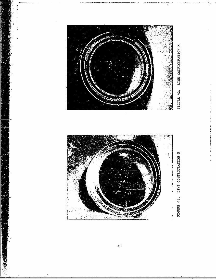
Six laminated self-sealing aluminum foil fuel lines were fabricated.Of the six, one has the configuration shown in Figure 35, three have theconfiguration shown in Figure 36, the fifth has the configuration shown inFigure 37, and the sixth has the configuration shown in Figure 38. Theprocedure used for the fabrication of these lines was similar to the onedescribed under Section Bla(2) which was the procedure Lsed for the fabricationof protected non-self-sealing laminated lines. The only exception here wasthat an additional step was taken to sandwich foam layers either betweenflexible ballistic nylon laminates or laminated aluminum foil layers. Thefoam was put under a precompressed state by means of a PVA film tape whichwas applied in such a way that it exerted a controlled pressure while thefoam was being bonded either to the flexible laminates or the laminatedaluminum foil. Figures 39, 40, 41, and 42 show cross-sections of each line
configuration depicting the foam layer or layers sandwiched between eitheL theflexible laminates or the laminated aluminum foil. The figures illustrate theline configurations V-l, V-2, W, and X, respectively, in Table II.
43
~1>
View of Entry Sides
i4
View of Exit Sides
FIGURE 34. LAMINATED Al FOIL FUEL LINES (3 LAYERS OF.003-INCH 5052-1!38 Al, FM-123 ADHESIVE)PROTECTED AND UNPROTECTED
44

1-Ply Flexible Ballistic Nylon Lamninates
I. -Laminated Aluminum Foil (7 Layers of .003-Inchý5652-H38 Al) Bonded with F,98 S~ealnvt
/ / / r Precompr~ss'ed Afd',Fuel Sensitive Foam,(i/4'Inch. Thick)
Lo' z2:2-2.
FUEL
FIGURE 35. NON-FLOWERING SEMI-METALLIC FUEL LINE SELF-SEALING CONCEPT-'LINE~ CONFIGURATION V-1
45

1-Ply Flexible Ballistic Nylon Laminates
1-Alumninum_ Foil ý(5O5.2-H38 AlF.OO3-Inch Thickj- 2 Layers Each,,Bonded with"898 Saat
____ ____ Precompressed and Fuel Sensitive Foam
_B4dd Sealant)..........................-..... ,.
FUEL
FICURE 36. NON-FLOWERING SEMI-METALLIC FUEL LINE SELF-SEALING CONCEPT-LINE CONFIGURATION V-2
46

i-Ply Flexible Ballistic Nylon Laminat
2-Ply Flexible Ballistic. Nylon Lmnt
Alumitnum. Foik (55 -H938' AI, .0 3--inch-rT Ticd j 2'Lyr a h
Bonded-wi th%;898'Sealant)
Precomp,ress'ed and. Etiiel ~Sensiftive FoAm, ('1/8-Inch Thick)
__2 e' 7' 7 i7 7- 77 7 .7Sr'i..i77 <
FUEL
FIGURE 37. NON-FLOWERING SEMI-.METALLIC .FUEL LýINE SELF-SEALING (l,.NCEPT-LINE CONFIGURATION W
1-Ply Flexible Ballistic Nylon Laminates
Alum~inum Foil .(5052-1138 Al,L.003-.InchThicki-2 Layers Each, Bonded,-with 898 Sealant),
-- !' Precompressed 'and Fuel SensitiVe Foam(lV8In~Thick),
el- . -- .~ -e. e,- -- - - -
7;*- v L. *= **....,.,, :. . .*
FUEL
FIGURE 38. NON-FLOWERING SEMI-METALLIC SELF-SEALING CONCTERLINE CONFIGURATIONX
47

C;,4
1-4
48z
rX4
E-4
C74z0
ra
64
ra
rZ4
49
Ballistic Tests
feIn the ballistic testsi teach line was inounted'to the test-setup and thefuel recycling system was used.,(se. Figure 1-),- The -fuel -flow pressure wasset at 35 psi. In the actual tests, the line with the configuration V-i wasimpacted by a .30 caliber AP projectile ini a 900 angle of incidence and 0' yaw.The three lines with the configuration- V-Zwere'iinpacted, one by a 30 caliber
4 AP projectile, in a 90' angled of incidence and' 00 yaw,. the secofid by a .30caliber AP projectile in a;,9,00 angle of incidence and slighttumbling, and thethird by a .50 caliber AP projecile in- a 909 anigle of incidence and 00 yaw.The results of all these self-sealing tests 're given in Table II.
C. DEVELOPMENT OF NON-FLOWERING PLASTIC FUEL LINES
If the materials,, design, and fabrication techniques are ,pý6perly selectedin the fabrication of plastic fuel lines-, the resulting !ines- should not floweror rupture and should reduce the impact damage to-a sealable, hole or even sealthe hole if a self-sealing ýystem is imbedded in the fuel line. Rigid, semi-rigid, and flexible plastic fuel l'ines cah be prepared. The rigidity orflexibility of the lines will depend upon the plastic components' used. Itis be'ieved that flexibility in the fuel line will enhance the protection
' efficiency of the fuel line. A very rigid plastic fuel line will tend torupture or crack easily; a more flexible plastic fuel line will not ruptureand will reduce the damage to a small sealable hole. Reinforcements such ashigh-strength cloth, high-strength filaments, or high-strength metal wire,imbedded in the resin, will vary and control the strength of the fuel linetubing. Keeping in mind the above considerations, a series of plastic fuellines were initially prepared and ballistically tested against .30 caliber
- ' AP projectiles.
1. Preparation of Plastic Fuel Lines
a. Plastic Fuel Lines Fabrication Procedure
A procedure has been developed for making plastic fuel lines 2½ inches indiameter and 3½ feet long. The line configuration is shown in Figure 43. Analuminum tube is used as the mold. Non-porous, Armalon is wrapped around the
, •tube as a mold release agent. Ballistic nylon layers are wrapped over theArmalon. The oallistic nylon is impregnated with a mixture of Epon 828,butyl glycidyl ether and Versamid 125. The wet ballistic nylon is held inplace by wrapping with polyvinyl alcohol plastic tape. The layup is curedin an oven at lOOF for 4 hours. After cure the metal tube is separated fromthe plastic tube.
' -b. Fabrication of Unprotected Plastic Fuel Lines and Ballistic Tests
Using the technique described above for preparing plastic fuel lines a2½-inch diameter and 3½-foot long plastic fuel line was prepared. It was
$' made up of three approximately 12-inch test sections containing 2-ply, 3-ply,and 4-ply ballistic nylon laminate sections. The ballistic nylon was
50

Plastic. Fuel2-Line '0-Ply, Ballistic, Nylbn Clothand Epoxy Resin, .058-Inch Thick, .34 ib/ft 2
FUEL
FIGURE 43. NON-FLOWERING PLASTIC FUEL LINE LINE CONFIGURATION Y
I-Ply Flexible Ballistic Nylon Laminate,
Plastic Fuel Line (2-Ply Ballistic Nylop. Clothand Epoxy Resin),
- i// //ii1iI il i-/III•Z
FUEL
FIGURE 44. NON-FLOWERING PROTECTED PLASTIC FUEL LINE -
LINE CONFIGURATION Z
51i5

impregnated with a mixture of Epon 828 and Versamid 125 (in a 2:1 ratio).Butyl glycidyl ether was added to the mixture for thinning of the mixture andSto allow better.penetration of the mixture into the ballistic nylon cloth.
The gunfiring was performed using the .30 caliber rifle with a 1-turn-per-10-inches rifling. The plastic fuel line was mounted to the fuel linetest setup. The water circulating system was used and the water flow pressurewas set at 35 psi. The first shot (.30 caliber AP) was fired into the 2-plyfuel line section at a 909 angle of incidence and O yaw. At the entrance,only a- small hole occurred. At the exit, a ½-inch slit with some minorfringing of nylon occurred. The water flow pressure through the line haddropped down to approximately 22 psi. Table III contains the results of thistest (see line configuration Y-1).
The shot in the 3-ply fuel line section gave a small hole at the entranceand a 1-inch slit with some minor fringing of nylon occurring at the exit.The water flow pressure dropped from 35 psi down to 27 psi.
The shot into the 4-ply fuel line section showed a tiny hole at theentrance side of the line and a ½-inch slit with minor fringing of the nylonat the exit side of the line. The water flow pressure dropped from 35 psidown to 30 psi.
After eachof the above shots, the damage was repaired using wet epoxynylon laminate (2-ply) patches wrapped around the damaged area. The patcheswere cured in an oven at 18OF for 1½ hours. After repair, similar shotsto those above were repeated. The results obtained were almost identical.A nonmetallic fuel line using PRD-49 high-strength fabric (2-ply) impregnatedwith 828 epoxy resin was compared ballistically with a nonmetallic fuel lineusing ballistic nylon cloth (2-ply) impregnated with 828 epoxy resin. Theresults indicated that the line using the ballistic nylon cloth was 5,,reriorin limiting damage to the fuel line
In another series of tests, a number of plastic fuel lines were preparedwhere the effect of the flexibility of the plastic fuel lines was investigated.These plastic fuel lines were made of epoxy/nylon. The flexibility of theselines was varied by using different epoxy resin (828 type) mixture formulationsIn the previous fabrication of epoxy fuel lines, the ratio of 828 resin to 125Versamid was 2:1. Using this ratio, the resulting plastic line tends to be-come slightly brittle. This probably accounts for the fringing of theballistic nylon cloth when the fuel line is ballistically tested. To lowerthe brittleness of the plastic fuel line material, the ratio of 828 resin to125 Versamid was varied (2:1.5 in one case and 1:1 in another case). Usingthese two new ratios, several plastic fuel lines were prepared having an I.D.of 2½ inches and a length of 3½ feet. The number of ballistic nylon clothlayers used in all the lines was two.
The techniques used for the fabrication of the lines was the one des-cribed above. The new lines with the ratios of 2:1.5 and 1.1 showed adefinite higher flexibility than those previously prepared using the 2:1epoxy/Versamid ratio. The degree of flexibility increased as the amount ofVersamid was increased.
52

The above plastic fuel lines, were ballistically tested against .30caliber AP projectiles using the fuel line test setup. For each test, theunprotected plastic fuel, lihe was mounted to. the fueL life tesisetup. Thewater circulating system was used with the water. 'flow pressure set at 35 psi.The gunfiring test was performed using the .30 caliber rifle with a 1-turn-pet-10-inches rifling.
In the test of the 'fuel line using;the 2:1.5 epgxy/Versamid ratio, theprojectile hit the line in a 90° angle of incidence and 00 yaw., After impact,the damage which occurred was a small-size 'hole at the entry with no cracking(low brittleness) of the laminated fuel line wal-, and low degree of fringing
V of the ballistic nylon cloth. At the exit, the projectile 'left a ý-inchlong slit with a minor degree of fringing on the inside or ouEside of theline. Similar 'shots with similar fuel lines were repeated two ,times andsimilar results were obtained. In all cases, the water flowpressure throughthe line after the shots dropped from 35 psi dowin to 25 psi. 'More details ofthe results are given in Table JII(see line configuration Y-2).,
The fuel lines using the 1:1 epoxy/Versamid ratio showed similar orslightly better results when compared with the lines using the 2:1.5 epoxy/-Versm4d ratio. The results of this test are given in Table III (see lineconfiguration Y-3).
c. Fabrication of Protected Plastic Fuel Lines and Ballistic Tests
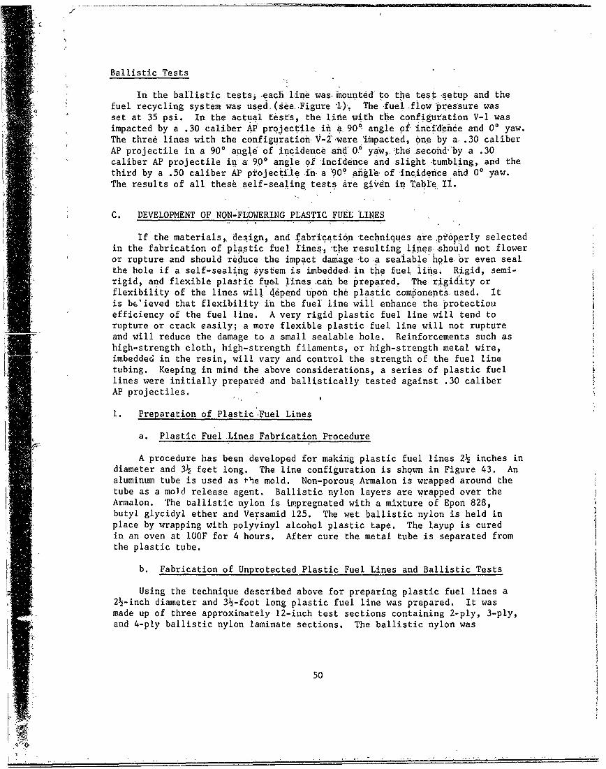
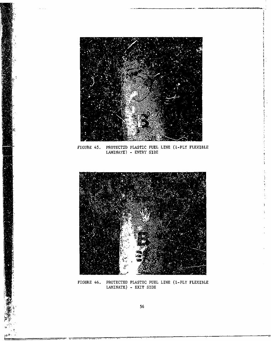
A 2½-inch diameter by 3½-foot long 2-ply ballistic nylon plastic fuelline was fabricated using the technique described above for preparing plasticfuel lines. The resin used was a mixture of Epon 828 and Versamid 125 (in a2:1 ratio). Butyl glycidyl ether was added for thinning of the mixture andto allow better penetration of the mixture into the ballistic nylon cloth.Upon completion of the semi-flexible fuel line, half of the line length wascovered with I ply of flexible ballistic nylon and the other half with 2 pliesof flexible ballistic nylon laminate using polysulfide 898 as the impregnatingsealant. The configuration of this line is given in Figure 44.;
The gunfiring test was performed using the .30 caliber rifle with a1-turn-per-lO-inches rifling. The 2-ply epoxy plastic fuel line with theprotective system (flexible laminate) bonded was mounted to the fuel linetest setup. The water circulating system was used in this test with thewater flow pressure set at 35 psi.
The first shot (.30 caliber AP) was fired into the section protected byI ply of the flexible composite at a 90' angle of incidence and 0' yaw. Atthe entrance (Figure 45), a pinhole size hole resulted, and on the insideof the line which was not protected, no fringing of nylon was noted. At theexit, the projectile left a ý-inch long slit with some fringing of nylon onthe cutside (see Figure 46) of the line and no fringing On the inside. Thewater flow pressure through the line dropped from 35 psi down to Z9 psi. This,compared to test results on an unprotected 2-ply ballistic nylon plastic fuelline, is a 7 psi decrease in pressure drop. For more results see Table III(line configuration Z-l).
53

0) ra a~ >.. 0. O6 CL - - -so)
ac 411 to .i.10 *Vc..Dp.10N00 VVI
H4 J! .41
410 61 I.' VA -. . I' X0 M0>0 4) N, 0' c
*k O 0~D 041.0 411 1- 0E0 0. 0 a b,0U'.~~~C. 0 .'.-0 ,1. -C 'VAO~, U 0, *.0 .0.0, :2 2O 'C'
010- 1 10--
-d .6 CL k A 0
--4 Lc 04m
4r 10 1 4 A
61001 0 0wo 1 ew o 4. - m 1
ul .0
cc C3, r 9:r.9
~~0I 411 a8. o
00 L
0 0 Q 0,
8cc
V 44
0cc
Zz..
0c -
cc o z
1.3' .2 d41c 0
fOuHV0M 00U.
z V >,.. V ." .Z! 6N *. -Z vio A. mN V ..
54

5 0 4 a ý6
0 z
O E Z -i-4 " -.
.c ke. ... 'O
WN~
EC L~U~OS
NUE a. rU . 4.
ba a ~ * CU~ ~~~ v - 4~~f
ZI'
945
L0 w0
0. 0* QU..-*c 01:*ý
wo 00 JJ4 . " >- -0 4J CO
EU EU55
1 1
FIGURE 45. PROTECTED PLASTIC FUEL LINE (1-PLY FLEXIBLELAMINATE) ENTRY SIDE
(
FIGURE 46. PROTECTED PLASTIC FUEL LINE (1-PLY FLEXIBLELAMINATE) - EXIT SIDE
56

The .30 caliber AP shot into the section protected by the 2-ply outer coverat a 900 angle of incid 'ence and 0' yaw showed, again, a small hole at the entryof the line and no fringing of nylon oi 'the inside of the line. At the exit,a 3/8-inch long slit occurred with no fringing of nylon on the inside or out-side of the line. The water flow pressure dropped from 35 psi down to 32 psi.Table III contains more results (see line configuration Z-I)-.
In another series of tests, two types of protected 2-ply ballistic nylonplastic fuel lines were prepared using the more flexible plastic fuel lines(epoxy/Versamid ratio of 2:1.5). In one case a 1-ply flexible ballistic nylonlaminate (using 898 sealant as the impregnating, resin) was wrapped around on theoutside of the lines and bonded to ',he lines using 898 sealant material (seeFigure 44). In the other case, a I-ply flexible ballistic nylon laminate(using 898 sealant as the impregnating resin) was wrapped around the outsideand the inside of the lines and bonded with 898 sealant (see Figure 47). Inthe latter case, the fabrication technique was as follows: an aluminum tube(O.D. of 2½ inches) was used as the mold. Non-porous Armalon was wrapped aroundthe tube as the mold releasing agent. A measured 1-ply flexible ballisticnylon laminate was wrapped over the Armalon. The two ends (overlapping by½-inch) of the 1-ply laminate were bonded together using 898 sealant underpressure at 180*F for I hours. After bonding of the 1-ply :aminate theimpregnated ballistic nylon layers (two) with the mixture of Epon 828, butylglycidyl ether, and Versamid 125 (a ratio of 2:1.5) were wrapped over the1-ply laminate. The wet ballistic nylon cloth was held in place and bondedto the laminate by wrapping with polyvinyl alcohol plastic tape (to applypressure). The layup was cured in an oven at 180°F for I hours. After cure,a 1-ply flexible ballistic nylon laminate (using 898 sealant as the impreg-nating resin) was wrapped around the outside of the lines and bonded to thelines using 898 sealant material which was cured at 180'F for I hours,
Ballistic tests were conducted with these protected lines similar to theones conducted with the unprotected lines. The results obtained showed thatthe protected lines performed very well and particularly the lines protectedon the inside and outside showed very promising results. In all cases, thedamage was low and the water flow pressure through the fuel line after theshots dropped only from 35 psi down to 32-33 psi. The detailed results aregiven in Table III. The line configuration Z-2 is the line with a 1-plyflexible laminate bonded on the outside of the plastic line and configurationXY is the line with a 1-ply flexible laminate bonded on the outside and insideof the plastic line.
A different type of protective system for plastic fuel lines was in-veotigated. In it a layer of foam is utilized as an additional damage controlsystem and/or a self-sealing system (see Figure 48). A 2-ply ballistic nylon!blastic tube using this type system was prepared using the technique describedabovw. A ¼-inch layer of natural rubber foam sheet was wrapped around theplastic tube and bonded using 898 polysulfide sealant. The foam was putunder precompression. A layer of ballistic nylon cloth impregnated with 898sealant was wrapped over the natural rubber foam layer and kept in place witha wrap of porous Armalon. The layup was cured in an oven at 100'F for 4 hours.Figure 49 shows a cross-section of the line depicting the foam layer sandwichedbetween the plastic line and the flexible laminate.
57

-1-Ply Flexible Balli.stic Nylon Taminate
Plastic Fuel Line (2-Ply Ballistic Nylon Clothand Epoxy Resin)
FUEL
FIGURE 47. NON-FLOWERING PROTECTED PLASTIC FUEL LINE -
LINE CONFIGURATION XY
1-Ply Flexible Ballistic Nylon Laminate
1/4-Inch Thick Foam Precompressed (Natural Rubber)
Plastic Fuel Line (2-Ply Ballistic Nylonand Epoxy Resin)
--=11111111Y.111 7/7 //// •//// ////// ///ZZZ
FUEL
FIGURE 48. NON-FLOWERING SELF-SEALING PLASTIC FUEL LINE -
LINE CONFIGURATION XZ

_____FIGURE 49. LINE CONFIGURATION XZ
59

The completed line was mounted to the fuel line test setup. The watercirculating system was used in. this test, with the water flow pressure set at35 psi. A .30 caliber AP projectile was fired at a 900 angle of incidence and00 yaw. As shown in Figure 50 and 51,. the d~iage Vhich occurred at both theentrance and exit sides was-only a pinhole size hole with n0 fringing of nylon,Upon impact, the line pressure dropped' slightly (as .witnessed on a high-speedmotion picture) but returned to the initial pressure of 35 ,psi within a shortperiod of time indicating sealing 6f the puncture. A similar test was con-ducted with a similar protected plastic line with the only.exception that fuelwas used instead of water as the circulating fluid. In this case, the naturalrubber foam performed even better inasmuch as sealing was obtained by both theprecompression of the foam and the swelliug of the foam in contact with thefuel.
D. DETERMINATION OF BURST AND COLLAPSE PRESSURES ON UNPROTECTED AND PROTECTED(NON-SELF-SEALING) LAMINATED AND PLASTIC FUEU LINES
A newly designed or developed fuel line has to be able to withstand thepressure changes which occur during aircraft operation. In view of this, testswere conducted to determine the burst and collapse resistance of unprotectedand protected laminated aluminum foil fuel lines (the soft and rigid types)
--- and unprotected and- 'rotected plastic fuel lines. The lines which weres•sjected to these tests are identified below:
a. Unprotected laminated aluminum foil fuel line with line configurationshown in Figure 18.
b. Protected laminated aluminum foil fuel line with line configurationshown in Figure 17.
c. Unprotected reinforced laminated aluminum foil fuel line (Line A;see "Bld(l) Ballistic Tests" section, page 41 and Figure 18).
d. Protected reinforeA laminated aluminum foil fuel line (Line B;see "Bld(2) BPI ; -c Tests" section, page 42 and Figure 17).
e. Protect , reinforced laminated aluminum foil fuel line (Line C;see "BI-2) Ballistic Tests" section, page 42 and Figure 17).
f . .. tected plastic fuel line with line configuration shown in-,re 43.
g. Protected plastic fuel line with line configuration shown inFigure 44,
60

FIGURE 50. PROTECTED PLASTIC FUEL LINE (FLEXIBLELAMINATE AND FOAM) - ENTRY SIDE
0
FIGURE 51. PROTECTED PLASTIC FUEL LINE (FLEXIBLELAMINATE AND FOAM) - EXIT SIDE
61

I. Burst Pressure-Test
a. Buirst Piessbre t~est ,Setup
This setup is shown in Figure 52. As showniit consists, of a clampingdevice in J~hi'ahthe l-ines to be tested are clamped and'a manifold comprised ofa pressure .-agei, apressurized air inlet and a water inlet. To apply pressurea hand-opeiit pump is used.
b. Pr66cdureof Test
Mount the line to. the setup as shown in Figure 52. To.,obtain a tightseal adtboth ends of the line, rubber stoppers are used.
" Fill thezline with water and gradually apply the water pressure tomaximudi (55 60psi). Observe if there is: any deformation of the line.
If no change:of the line is observed to that point, then proceed withincreasing the pressure gradually by using the hand-operated&pump ofthe setup. The pressure is increased until deformation or burst of theline occurs. At that point, the pressure is noted.
Test Results
According to MIL-F-3836 3B (USAF) the fuel system and its components,excluding the vent and the refueling subsystems, shall be designed for anoperating pressure of 60 psi; a proof pressure of 120 psi without malfunction,failure, permanent distortion, or external leakage; and an. ultimate pressureof 180 psi without external leakage. The proof and ultimate -pressure of thevent subsystem shall be two and three times the operating pressure, respectively.The refueling subsystem shall be designed for an operating pressure of 120 psi,a proof pressure of 180 psi, and an ultimate pressure of 240 psi.
In an actual burst test, the pressure was gradually increased to up to240 psi. All the test lines ,described above were exposed to 240 psi pressure"and no changes or deformations of the lines were noted. Thus, all the linespassed the burst test successfully.
2. Collapse Pressure Test
a. Test Setup Used
"The test setup used here was the same as the one used for the burstpressure tests.
b. Procedure of Test
Mount the line to the setup as shown in Figure 52. To obtain a tight
seal at both ends of the line, rubber stoppers are used.
• Connect the vacuum pump hose to the setup and gradually pull the vacuum.The pressure drop is measured with a manometer.
- 62

iI
FIGURE 52. BURST AND COLLAPSE PRESSURE TEST SETUP
I6
i: 63

Test Results
The lines in (c), (d), (e), (f), and (g) described above resisted a highvacuum (z29.5 inches of Hg). No changes or deformations of the lines occurred.The line configuration (a) sta ted to deform or collapse at 17 inches of Hgand the line configuration (b/ started to deform or collapse at 19 inches of Hg.
E. HYDRAULIC RAM EFFECT
The action of a penetrating projectile (.30 caliber AP) through a fuelline filled with a fluid was captured by high-speed photography. This wasaccomplished by using an acrylic (transparent) line measuring 24 inches longand having a 2½-inch I.D. This line was mounted to the fuel line test setupwith water flowing through the line at an initial 35 psi pressure. Thephenomena taking place inside 'the line when the projectile traverses was cap-tured by the film before the acrylic line broke. The analysis of the filmindicates that the projectiledoes not have time to tumble while travelingthrough 2½ inches of water after impacting the line in a 90* angle of incidenceand 0' yaw. The projectile entered in a straight position and exited in astraight position. The cavitation formed behind the projectile traversingthe water is cylindrical. The pressure generated was of large magnitudeand appears to be concentrated on the wall area around the point of impact.
64

SECTION III
SUMMARY AND CONCLUSIONS
1. The Objective of this program was the development of new and improvedlightweight slf.-sealihg fuel line composites that reliably seal woundsinflicted by .30 'nd .50 caliber AP projectiles.
2. The types of fuel lines evaluated under this program were:
a. Alumihum fuel line tubing 0.028 inches thick based on aluminumalloy 6061-T4-AL.
b. Laminated aluminum foil fu1l lines based on 1100-0 (essentiallypure aluminum) and 5052-H38 (an aluminum alloy) using flexible to rigidadhesive materials as interlaminar bonding agents.
. Integrated aluminum foil fabric or compressed foam reinforcedfuel line composites wherein a ply of ballistic nylon or natural rubberfoam is interspersed between plies of aluminum foil bonded togetherusing a flexible adhesive material as the interlaminar bonding agent.
d. Plastic laminated ballistic nylon or PRD-49 fabric reinforcedfuel line composites impregnated with various epoxy resin sealant/adhesive binders.
3. Plastic fuel lines fabricated using 2 to 4 plies of ballistic nylonor PRD-49 impregnated with the epoxide resin adhesive binders sufferedthe least damage when punctured by .30 caliber projectiles. Damage tothe entry wall was a small hole. On exiting, the projectile producedslit wounds 1/2 to 1 inch in length and caused the fabric to fray. Theextent to which fraying occurred decreased as the ratio of epoxy resinto polyamide curing agent was adjusted to yield a more flexible fuelline composite. Results of these tests indicated ballistic nylon to besuperior to PRD-49 as a fabric reinforcing component.
4. The laminated aluminum foil fuel lines suffered less damage thanthose prepared using aluminum foil 1100-0 which is essentially purealuminum. A ply of ballistic nylon bonded to the inside and outsideof the laminated aluminum foil fuel line was found to be sufficientfor limiting the damage to sealnble size wounds.
S. The damage caused by .30 and .50 caliber projectiles to the entrywall of a standard 28 mil thick aluminum fuel line tubing was limitedto holes about the size of the projectile. On exiting the projectilepunctured relatively large holes and tore the metal causing it to petaloutward (flower) extensively. Applying 2 to 4 plies of ballistic nylon
6S

impregnated with the 898 polysulfide sealant to the outer surface of astandard aluminum fuel line was effective in reducing overall damagebut did not entirely eliminate flowering.
6. The compressed foam sealant concept proved to be, effective forproviding self-sealing protection. The plastic laminated fuel lineprotected by a 1/4 inch thick layer of natural rubber foam held in acompressed state by an outer ply of ballistic nylon impregnated withpolysulfide sealant 898 successfully sealed wounds inflicted by .30and .50 caliber projectiles. This self-sealing plastic fuel linecomposite weighs 0.83 lbs./ft2, a third of the weight (2.59 Ibs.ft2)
of a standard aluminum fuel line shielded by a .50 caliber naturalrubber gum fabric reinforced self-sealing protective cover.
7. Similar test results, were obtained with self-sealing integratedaluminum foil compressed foam, fabric-reinforced fuel line composites.The lightest weight self-sealing fuel line composite of this typefabricated that demonstrated a self-sealing capability at the .50 cal-iber projectile threat level weighed approximately 1.11 lbs./ft 2 .
8. A composite comprised of a 1/4 inch thick layer of precowpressednatural rubber foam sandwiched between plies of ballistic nylon fabricimpregnated with polysulfide sealant 898 was evaluated as a protectivecover for standard aluminum fuel line tubing. It proved to be effectivefor controlling damage and sealing wounds at the .30 caliber level ofthreat but not at the .50 caliber projectile threat level.
9. Hydraulic and vacuum pressure tests were performed on both thelaminated aluminum foil and the plastic fuel lines with and withoutinner and outer protective plies of ballistic nylon impregnated withpolysulfide sealant 898. Results of hydraulic pressure tests showedall cf the laminated fuel line composites to be capable of with-standing pressures up to at least 240 psi without deforming. Theplastic fuel line composite and the laminated aluminum foil fuel linecomposites prepared using an epoxy adhesive did not deform whensubjected to a hard (29.5 inches of Hg) vacuum. Laminated aluminumfoil fuel lines with and without an inner and outer protective ply ofballistic nylon fabricated using polysulfide 898 as the impregnatingsealant and interlaminar bonding agent began to collapse when subjectedto partial pressures of 19 and 17 inches of Hg, respectively.
66

SECTION IV
RECOMMENDATIONS AND FUTURE. WORK
1. Continue the development of prot.etion systems and self-sealing systemsfor preventing rupturing and flowering of semi-metallic and plasticfuel lines. Emphasis should be put on optimizing the laminated aluminumfoil fuel lines and plastic fuel lines for weight, thickness, and efficiencyagainst .50 caliber AP projectiles either impacting in a 90' angle ofincidence and 0' yaw or in a tumbled condition and against .60 caliberprojectiles.
2. The above systems should be evaluated for use against the higher threatprojectiles and new or improved protection and self-sealing systemsshould be investigated and developed.
3. Curved laminated aluminum fuel lines and curved plastic fuel lines shouldbe fabricated and evaluated.
4. Laminated aluminum fuel lines joints and plastic fuel lines joints shouldbe fabricated and evaluated.
5. The unprotected and protected fuel lines developed should be evaluatedagainst high explosive projectiles exploded in air and in fuel.
66
*U.S.Government Printing Office: 1974- 657-026/285