UNCLASSIFIED AD NUMBER - geekgunman.com · UNCLASSIFIED AD NUMBER AD849576 NEW LIMITATION CHANGE TO...
45
UNCLASSIFIED AD NUMBER AD849576 NEW LIMITATION CHANGE TO Approved for public release, distribution unlimited FROM Distribution authorized to U.S. Gov't. agencies and their contractors; Administrative/Operational Use; JAN 1969. Other requests shall be referred to Army Aberdeen Research and Development Center, Aberdeen Proving Ground, MD 21005. AUTHORITY USAMSAA ltr, 17 Nov 1977 THIS PAGE IS UNCLASSIFIED
Transcript of UNCLASSIFIED AD NUMBER - geekgunman.com · UNCLASSIFIED AD NUMBER AD849576 NEW LIMITATION CHANGE TO...

UNCLASSIFIED
AD NUMBER
AD849576
NEW LIMITATION CHANGE
TOApproved for public release, distributionunlimited
FROMDistribution authorized to U.S. Gov't.agencies and their contractors;Administrative/Operational Use; JAN 1969.Other requests shall be referred to ArmyAberdeen Research and Development Center,Aberdeen Proving Ground, MD 21005.
AUTHORITY
USAMSAA ltr, 17 Nov 1977
THIS PAGE IS UNCLASSIFIED

II
S FA D
Ifhh
MEMORANDUM REPORT NO. 1953
A COMPARATIVE EVALUATION OF
4 THE 7.62MM AND 5.56MM, G-3 ASSAULT RIFLES
b by
Thomas E, CarlsonDavid A. Golm
January 1969
This aocuient ii subject to special expOrt controls and each transrmittal It.o foreign governmenlts or foreign nationals may be made onl~y with prior
approvel of CowAnaing Officer, U.S. Army Aberdeen Research and OevelopmentCenter, Azerdeen Proving Ground. Marjyland.
1
U.S. ARMY ABERDEEN RESEARCH AND DEVELOPMENT CENTER
BALLISTIC RESEARCH LABORATO)RIESABERDEEN PROVING GROUND, MARYLAND
S,. -(: ', ""
I' Al

w -
BALL L.. T I C R E S EA A C H LA BO R ATO R I ES Sj
MEMORANDUM REPORT NO. 1953
JANUARY 1969
A COMPARATIVE EVALUATION OF THE 7.62mmAND 5.56mm, G-3 ASSAULT RIFLES
Thomas E. Carlson 1David A. Golm
Interior Ballistiis Laboratory
This document is subject to special export controls and each transmittal 4to foreign goveorants or foreign natiorals may be made only with priorapproval of Cocsanding Officer. V.S. Amy Aberdeen Researcn and OevelopmentCenter. Aberdeen PFrvlng Ground, Harylgnd.
kDME Project No. 1W523801A304
ABERDEEN PROVING GROUNDs MARYLAND
* I
D
p®BALLISTIC RESEARCH LABORATORIES
MEMORANDUM REPORT NO. 1953
TECarlson/DAGolm/nlgAberdeen Proving Ground, Md.January 1969
*
A COMPARATIVE EVALUATION OF THE 7.62mnAND 5.56am, G-3 ASSAULT RIFLES
ABSTRACT 4 *A test was conducted with 7.62mm and 5.5 6 mm, G-3 Assault Rifles to
evaluate and compare the kinematics, reliability, safety feati~res,
physical characteristics, reccil impulse, rates of fire, projectile
velocities, muzzle motion and accuracy of the weapons. No serious
problems were detected during the tests and the reliability of the
weapons was comparable.
D4
*3
p4
IAO
* a
4 I
TABLE OF CONTETSP
ABSTRACT ................ .......................... 3
LIST OF ILLasTRATIONS ................. . 7
LIST OF TABLES ....................... 8
LIST OF SYMBOLS . .... ............... . 9
I. INTRODUCTION ........................ i4
II. PROCEDURE AND EQUIPMEN.T . . . . . . 11
III. RESULTS .......................... 17
A. Physical Measurements .......... ................. 17B. Description of Mechanism. ...................... .200 4C. Malfunctions .......................... 29
D. Firing Data ........ ...................... . . 33
IV. DISCUSSION ..... ................ . . . . . . . . . .42
A. Reliability ...... ................. . . . . . 42 4
B. Performance......................... . . . . . .43C. Bolt latch ....... .................. . . . . .43D. Bolt-Bolt Carrier Gap ................. 43
E. Possible Changes ...................... 43
F. Damping Device ..... .............. . . . . . . .44
G. Weight. . ........ ........... . . . .44
R]ErICES . ............. * ........ 45
DISTRIBUTION LIST ........ ................... . . .. 7
5
4 1 4

®' I®
LIST O LUTAIN
Figure Page
1 7.62mm, 0-3 Assault Rifle, Assembled and Unassembled .... *12
2. 5.56mtn, 0-3 Assatlt Rifle, Assembled and Unassembled . . . . 13
3. 7.62mm, 0-3 Assault Rifle in Machine Rest ..... ......... 14
4. Bolt Assembly with Bolt Carrier Reflector ..... ......... 14
5. Bolt Asseably with Bolt Reflector ........ ............. 15
6. 5.56mm, 0-3 Assault Rifle, in Mount used for Simulating 16Shoulder Firing ........ ... .....................
7. Moment Arms about Center of Gravity and Bu~tplate ... ..... 20
8. Displacement-Time Record of Bolt Carrier, 7.62mm, 0-3 . 22
9. Displacement-Time Record of Bolt Carrier, 5.56mm, 0-3 . 23
10. Locking Me.-hanism . ... ............... 24
311. Operation of Bolt Latch .............. . 25
12. Conmonents of the L'ocking Mechanism .... ............ .. 26
13. Bolt Assembly with Lead Filings for Damping, 5.56mm, 0-3 • . 29
14. Charging Assembly and Mechanism, 5.56mm, G-3 .... ........ 29
15. Displacement-Time Record of Bolt Carrier 5.56, G-3, without 31Imbrication ..... .......................
16. Bolt Carrier Displacement with Normal and Excessive Delays, 327.62mm, G-3 .......................
17. Displacement and Velocity of the Bolt Carrier, 5.56mm, G-3 .37
18. Bolt and Bolt Carrier Bounce ...................... 38
19. Vertical Mazzle Motion of Newer, 5.56mm, 0-3 .... ........ 41
20. Dispersion Patterns of five 10-Round Bursts .... ........ 42
7
4 0I
q D @

LIST OF TABLES
Table Page
I. Weights . .. .. ...... . ...... .... 17
II. Lengths . . . . . . . . ........ . . . . . . . . 18
III. Sprin Calibrations ..... .................... .... 18
IV. Moment Arms and Moments of Inertia ... ........... . 19
V. Malfunctions. ........................ . . . 30
VI. Rates of Fire . . . . . . . . ...... . . . . . . 33
VII. Comparison of Initial and Succeeding Cycles . . ...... 34
SVIII. Rates of Fire with Modifications . . . . . . . . . . 35
IX. Bolt Assembly Velocity . ... .......... .. 36
X. Bolt Carrier Bounce .................... . . . . . 39
XI. Recoil Impulse ................... . . . . . 40
XII. Projectile Velocity ............ .... 40
I •
* 6
* 0

® * ®
LIST OF SYMBOTIO~
F1 force required on the face of the bolt to release the lockingmechanism, lb
4 F2 force requirel on the connecting rod to release the lockirngmechanism, lb
VC, forc applied by the bolt latch spring, lb
h distance measured vertically from center of bore to center ofS�buttplate, in.
1bp moment of inertia about a horizontal transverse axis rassingthrough the center of buttplate, lb ft sec2
leg mment of inertia about a horizontal transverse axis passingthrough the center of Fravity, lb ft sec 2
* SJ recoil impulse, lb sec
N number of rounds in statistical sample
R rate of fire, shots per min (SPM)
0 * V velocity of bolt assembly, ft per sec (fps) S *Vn ~muzzle velocity of projectile, ft per seC (fps)
Xeg distance measured parallel to bore from center of buttplate, in.
Ycg distance measured vertically from center of bore to center ofgrevity, in. p
a angle of mating surfaces on bolt and bolt latch, deg
a angle of ramp for locking rollers on connecting rod, deg
* aj standard deviation in measured recoil impulse, lb sec
a standard deviation in rate of fire, shots per minute (8PM)
ov :standard deviation in vplocities, ft per sec (fps)
# angle of ramp for lockL.g rollers in locking recesses, deg
9
4I
L. - 9I t
* 0~~~ 0

O S*!
1. Th'TRDUCTION
The 7.62nu, G.3 Assault Rifle, which fires the MBO NAMO round, has
been in use by the German Armed Forces Zor a number of ye-L. -. It is
essentially an improved version of the earlier Spanish CETME Assault
Rifle and has proved quite reliable. It fires in both the semi-automatic
and automatic modes and is fed from a 20-round, box-type magazine. Most
of the parts of the G-3, with the eyeception of the barrel and the bolt
assembly, are made of stamped sheet steel, which makes the system easy
to mass- produce.
The increasing interest in small calibers, particuiarly 5.56mm,
prompted the development of a scaled-down version of the 7.62mm, weapon.
The rcaled-down model, produced by Harrington and Richardson, Inc., of
14assachusetts, in association with Heckler and Koch, G. Y. B. H. of
West Germany, fires the 5.56mm, 2193 round. The mechanigm of the 5.56mm
weapon differs from the '1.62mm version only ii, a few minor respects.
S*The most notable of these are the addition of a catch to keep the bolt
open after the last round of a magazine is fired and the use of adamping device in the bolt assembly of the 5.56mm weapon.
At the request of U.S.A. Weapons Command, two 5.56mm rifles and one
7.62mm rifle were delivered to the Interior Ballistics Ik-boratory of
Aberdeen Proving Ground for test and evaluation. Studiqs of physical
characteristics, kinematics and reliability of the mechanisms, projectile
velocities, muzzle vibration and accuracy of fire were requested.
SII EqunMT AED PROCEDURE
One 7.62m., G-3 rifle and two 5.56mm, G-3 rifles were fired duringthe tests. Gan No. HK 2803 was a 7.62mm rifle on which the history wasunknown, but it appeared from the wear of the parts that less than 5000
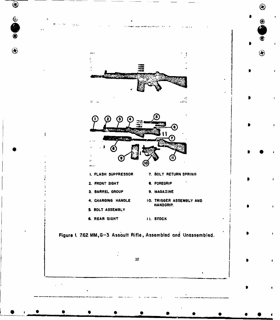
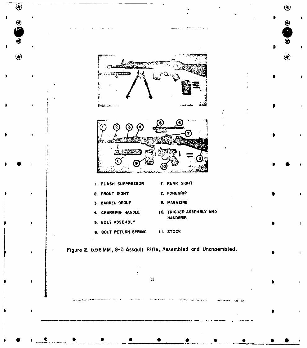
4 rounds had been fired from the weapon. The weapons are shown assembledand unassembled in Figures 1 and 2. The weapons were fired under
laboratory conditions and in most cases from a machine rest mounted as
shown in Pigure 3.
11
• t - • • •@ • •
@ 4 " " i9 9 i- m ! -• -* i . .. • .. *
3 1
3 4
7P
® .... .®.
9*
C Ie
It
0 I 0
I. FLASH SUPPRESSOR 7. BOLT RETURN SPRING
2. FRONT SIGHT S. FOREGRIP
3. BARREL GROUP 9. MAGAZINE
4. CHARGING HANDLE 10. TRIGGER ASSEMBLY AND"HANDGRIP. •
. BOLT ASSEMBLY
"6. REAR SIGHT II. STOCK
Figure I. 7.62 MM,G-3 Assault Rifle, Assembled and Unassembled. 1
12 5
I
@... . 0 l I l .. . • i:n ••:i .. . I0 -0i 0•I i 0
)I
4 I q
-4 (
II
& -'. -. "* ..4 .... "
ro
I. FLASH SUPPRESSOR 7. REAR SIGHT
2. FRONT SIGHT e. FOREGRIP 4
3. BARREL GROUP 9. MAGAZINE
4. CHARGING HANDLE IO. TRIGGER ASSEMBLY ANDHANDGRIP.
5. BOLT ASSEMBLY
6. BOLT RETURN SPRING II. STOCK
Figure 2. 5.56 MM, G-3 Assault Rifle, Assembled and Unassembled.
13
0 4 0 0 0 0 • 0 0
(VF,
I® 4
* 0t T®
moin a yidiaielco a heae noahl ntetpo
4 o rvlc h refleto. A elcoUasas otd~ toth
I-
S- : -* - .
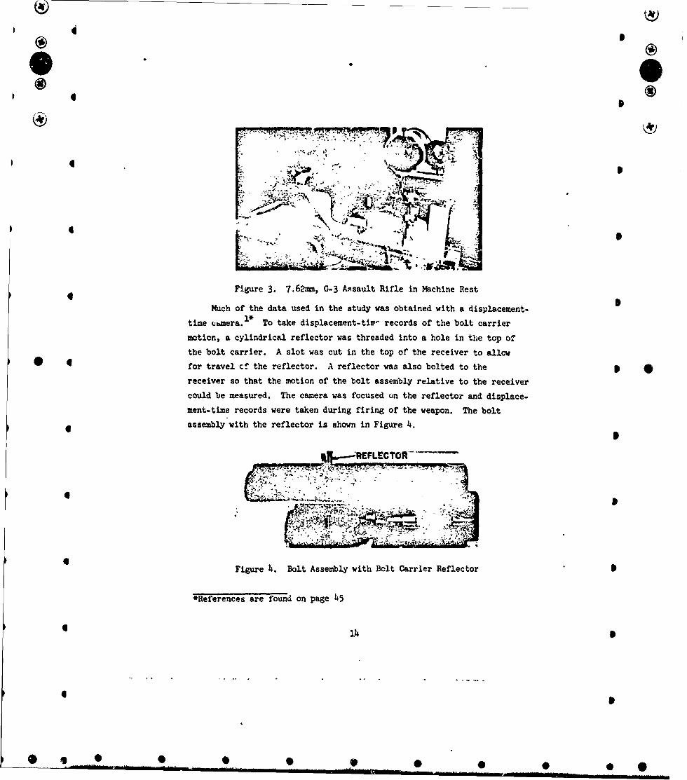
rec Figure 3. 7.62mm, G-3 Atsault Rifle in Machine Rest
Much of the data used in the study was obtained with a displacement-
time rmera. ds To take d uri n records of the bolt carriermotibn, a cylindrical reflector was threaded into a hole in the top ofthe bolt carrier. A slot was cut i'n the top of the receiver to allow
0 for travel c-! the reflector. A reflector was also bolted to the p
receiver so that the motion of the bolt assembly relative to the receiver
could be measured. The camera was focused on the reflector and displace.
ment-time records were taken during firing of the weapon. The bolt* assembly'with the reflector is shown in Figure 4.
ý, REPLECTOR--A!
Figure 4. Bolt Assembly with Bolt Carrier Reflector S
*References are found on page 45
4 14
4
O i • •• i• • •

D 4
®I
In some instances it was necessary to record the motion of both the
bolt and the bolt carrier. Because the reflector on the bolt was
I* perpgendicular to the center line of the reflector on the bolt carrier,
a system of mirrors was used to project the images of the reflectors
into the camera. The reflector used to record bolt motion is shcwn in
Figure 5.
REFLECTOI
Figure 5. Bolt Assembly with Bolt Reflector
* O * The displacement-time records were used to calculate the velocity
and acceleration of the bolt carrier, the rate of fire and xo explain
irregularities of operation. Studies of minute details of functioning,
such as hammer swing or bolt bounce were made when the records indicated
unusual or critical behavior in the mechanism. Displacement-time records
* 0 of the muzzle motion were taken by focusing the camera on a reflector
epoxied to the outer wall of the barrel at the muzzle. The records were
used to d'ctermine the frequency and amplituae of muzzle vibrations.
Four lumaline screens were used to determine projectile velocities
• at three points along the trajectory. The times elapsed while the
projectile traveled between screens were recorded with digital counters.
Using these times and the distances between the screens, the average
velocities between screens were calculated and the velocity at the muzzle
"tas determined by extrapolating from the plotted data.
Some timulated shoulder firing was done for comparison with the
firing done in the machine rest. For this purpose a frame was built
which allowed the weapon freedom of movement only along the line of
recoil and counterrecoil as shown in Figure 6.
15• ItS
• .. ....... 0 0.... .. 0 * ,•
T7*
wow4 -Xi
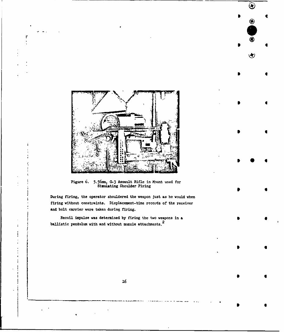
Figue 6 5.5mmG-3 ssalt iflein ountuse fo
Simulating Shule Fiin
During firing, the operator shouldered the weapon just as he would whenfiring without constraints. Displacement-time r~cords of the receiverand bolt carrier were taken during firing.
Recoil impulse was determined by firing the two weapons in aballistic pendulum with and without muzzle attachments. 2
16

III. RESULTS4 4
A. Physical Measurements
Table I. Weights, pounds
CoNETS 7.62 5.5
Weapon Empty 9.430 8.16Weapon and Magazine 9.740 8.41
Weapon and Magazine + 20 Rounds 10.810 8.91Sling - - - 0.27
* Bayonet - - - o.65 4Tripod - - - 1.015Bolt 0.220 0.200Bolt Carrier 1.355 0.900
* Connecting Rod 0.085 0.085 * *Firing Pin 0.020 0.015Receiver and Barrel Group 4.150 1..940Trigger Mechanism 1.350 1.O4O
Stock 1.490 1.150* Foregrip o.4•O 0.370
* D
17
* .. . ...-- -... I I
I *
4®) .
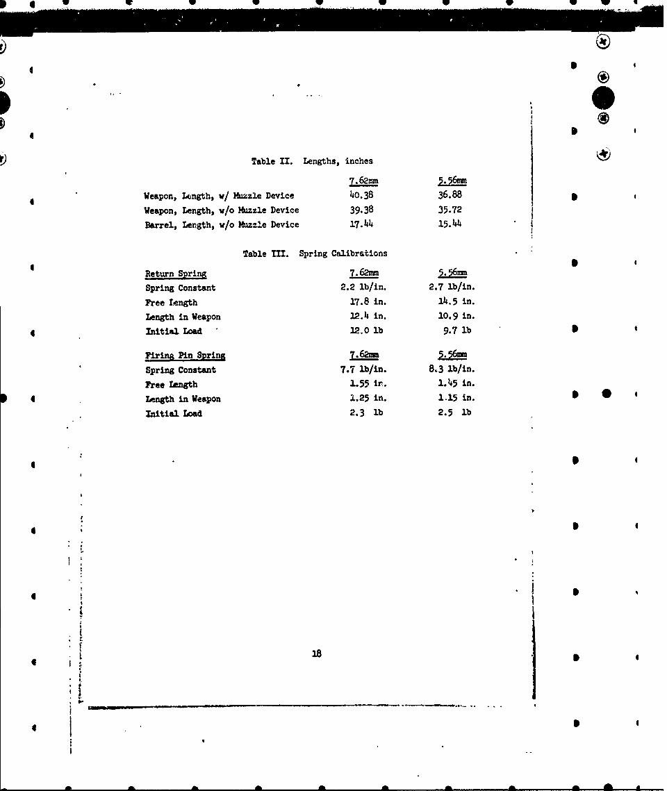
Table II. Lengths, inches
Weapon, Length, w/ Muzzle Device 40.38 36.88 *Weapon, Length, w/o Muzzle Device 39.38 35.72 1
Barrel, Length, w/o Muzzle Device 17.44 15.44
Table Mfl. Spring Calibrations
Return Spring .5
Spring Constant 2.2 lb/in. 2.7 lb/in.
Free Length 17.8 in. 114.5 in.
Length in Weapon 12.4 in. 10.9 in.
Initial Load 12.0 lb 9.7lb l
Firina Pin Spring 7. 5.
Spring Constant 7.7 lb/in. 8.3 lb/in.
Free length 1.55 In. 1.45 in.
Length in Weapon 1.25 in. 1.15 in. S 0Initial Load 2.3 lb 2.5 lb
tL Af A
I.
*
*ij mT- ~
4 I

I 4
II
I
Table IV. Moment Arms end Moments of Inertia
Weapon + Magazine 7 .2
h (in.) 2.304 2.161 IIcg (lb ft see 2 ) 0.1485 0.1054
(lp (b ft sec2 ) o.e881 o.67w
xcg (in.) 18.970 18.280Yc9 (in.) 0.366 0.246 4
Weapon + Magazine + Bayonet
h (in.) 2.304 2.161
Icg (lb ft sec2 ) 0.1509 0.1422
1bp (lb ft see2 ) 0.9704 0.3584xeg (in.) 18.94 19.620
Ye (in.) o.645 0.093
Weapon + Magazine + 20 Rounds
h (in.) - -- 2.161
0cg (lb ft sec2 ) T- 1060
(bp (lb ft see2) - - - 0.7112Xcg (in.) - -- 18.22Yeg (in.) - - - 0.361
Weapon + Magazine + 20 Rounds + Bayonet In (in.) - - - 2..161
S(lb ft see2 ) - 0.143' (lb ft se(?) 0.8
xcg (in.) - -- .19.4 I' cg (in.) - -- 0.32
NOTE: leg Is the momert of inertia about a horizontal transverse axis
passing through the center of gravity, lb ft see2 .
1 Ip is the moment of inertia about a horizontal transverse axis
passing through the center of the buttplate, lb ft sec2 .h is the distance measured vertically from center of bore to
center of buttplate, in.
19
I 4
4
I ! Ih ®"i
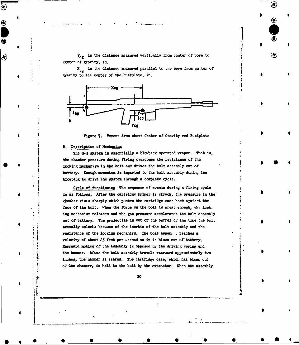
Ycg is the distance measured vertically from center of bore to (center of gravity, in.
X~g is the distancc measured parallel to the bore from center of
gravity to the center of the buttplate, in. 4
XCO
4Up
h
Figure 7. Moment Arms about Center of Gravity and Buttplate
B. Description of Mechanism
The C-3 system is essentially a blowback operated weapon. That is,
t the chamber pressure during firing overcomes the resistance of the 0locking mechanism in the bolt and drives the bolt assembly out of
battery. Enough momentum is imparted to the bolt assembly during the
blowback to drive the system through a complete cycle.
Cycle of functioning The sequence of events during a firing cycle
4 is as follows. After the cartridge primer is struck, the pressure in the
chamber rises sharply which pushes the cartridge case back ajainst the
face of the bolt. When the force on the bolt is great enough, the lock-
ing mechanism releases and the gas pressure accelerates the bolt assembly
out of battery. The projectile is out of the barrel by the time the boltactually unlocLs because of the inertia of the bolt assembly and the
resistance of the locking mechanism. The bolt assen, , reaches a
* velocity of about 25 feet per sbcond as it is blown out of battery.
Rearward motion of the assembly is opposed by the driving spring and
4 * the hammer. After the bolt assembly travels rearward approximately two *
inches, the hamer is seared. The cartridge case, which has blown out
* a of the chamber, is held to the bolt by the extractor. When the assembly
20
ii*
!I f
4 1
4 I~® 4
4 4
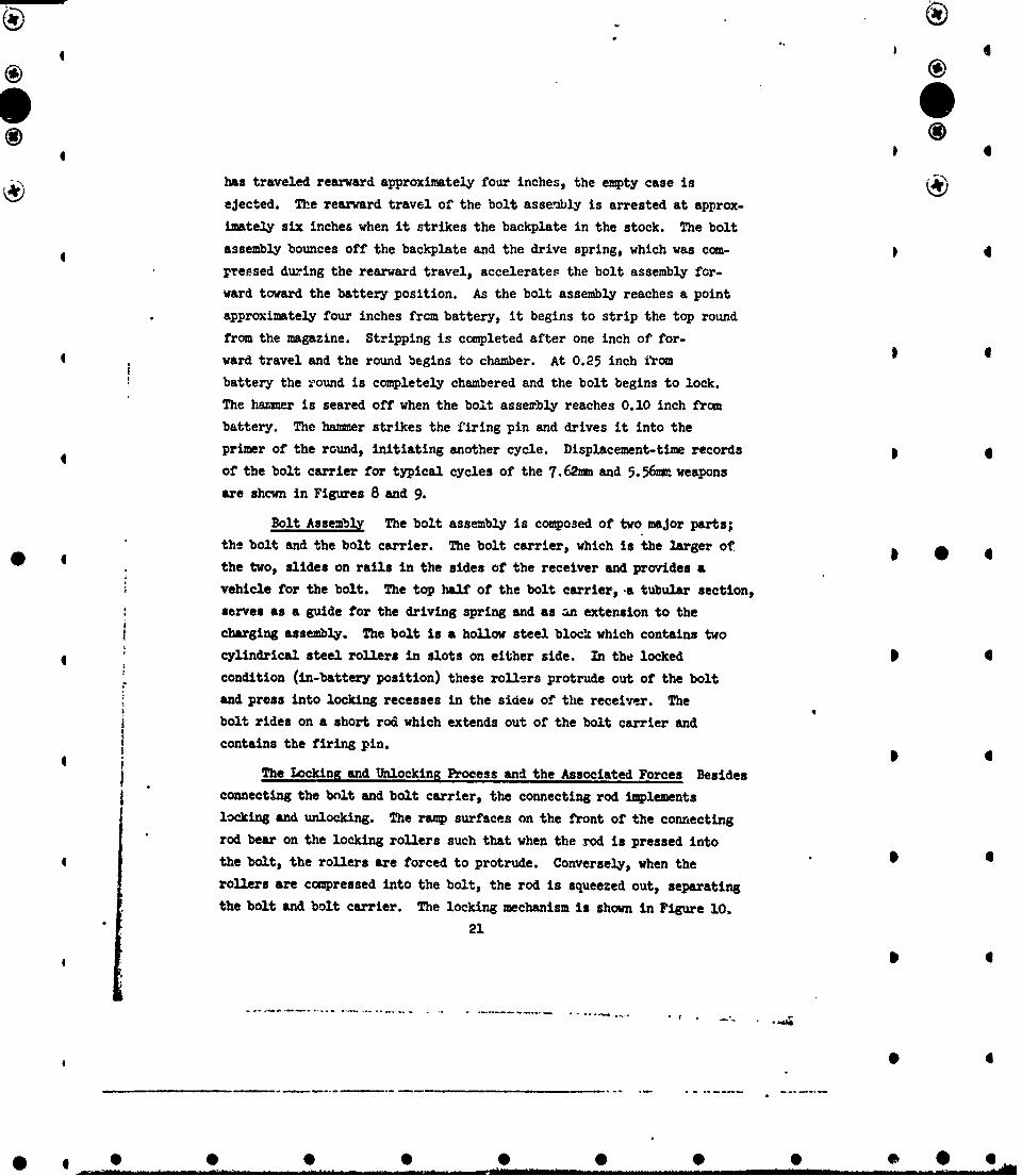
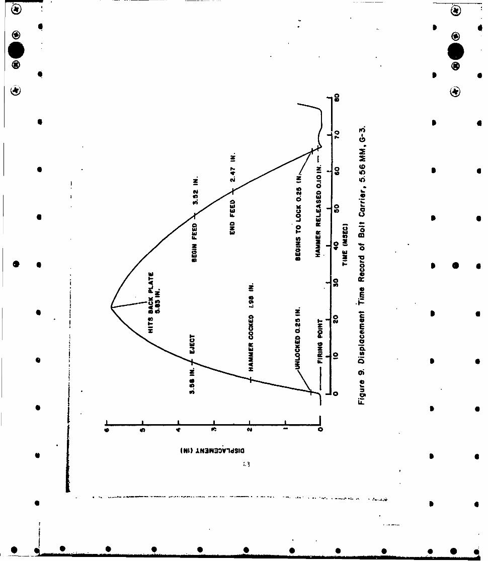
has traveled rearward approximately four inches, the empty case is N
ejected. The rearward travel of the bolt assembly is arrested at approx-
imately six inches when it strikes the backplate in the stock. The bolt
assembly bounces off the backplate and the drive spring, which was com-
pressed diuring the rearward travel, accelerates the bolt assembly for-ward toward the battery position. As the bolt assembly reaches a point
approximately four inches from battery, it begins to strip the top round
from the magazine. Stripping is completed after one inch of for-ward travel and the round begins to chamber. At 0.25 inch irom
battery the round is completely chambered and the bolt begins to lock.
The hammer is seared off when the bolt assembly reaches 0.10 inch from
battery. The hamer strikes the firing pin and drives it into the
4 primer of the round, initiating another cycle. Displacement-time recordsof the bolt carrier for typical cycles of the 7. E2m and 5.56, weapons
are shcwn in Figures 8 and 9.
Bolt Assembly The bolt assembly is composed of two major parts;the bolt and the bolt carrier. The bolt carrier, which is the larger of,
the two, slides on rails in the sides of the receiver and provides avehicle for the bolt. The top half of the bolt carrier, .a tubular section,
serves as a guide for the driving spring and as an extension to the
charging assembly. The bolt is a hollow steel block which contains two4 cylindrical steel rollers in slots on either side. In the locked 4
condition (in-battery position) these rollers protrude out of the bolt
and press into locking recesses in the sides of the receiver. The
bolt rides on a short rod which extends out of the bolt carrier and
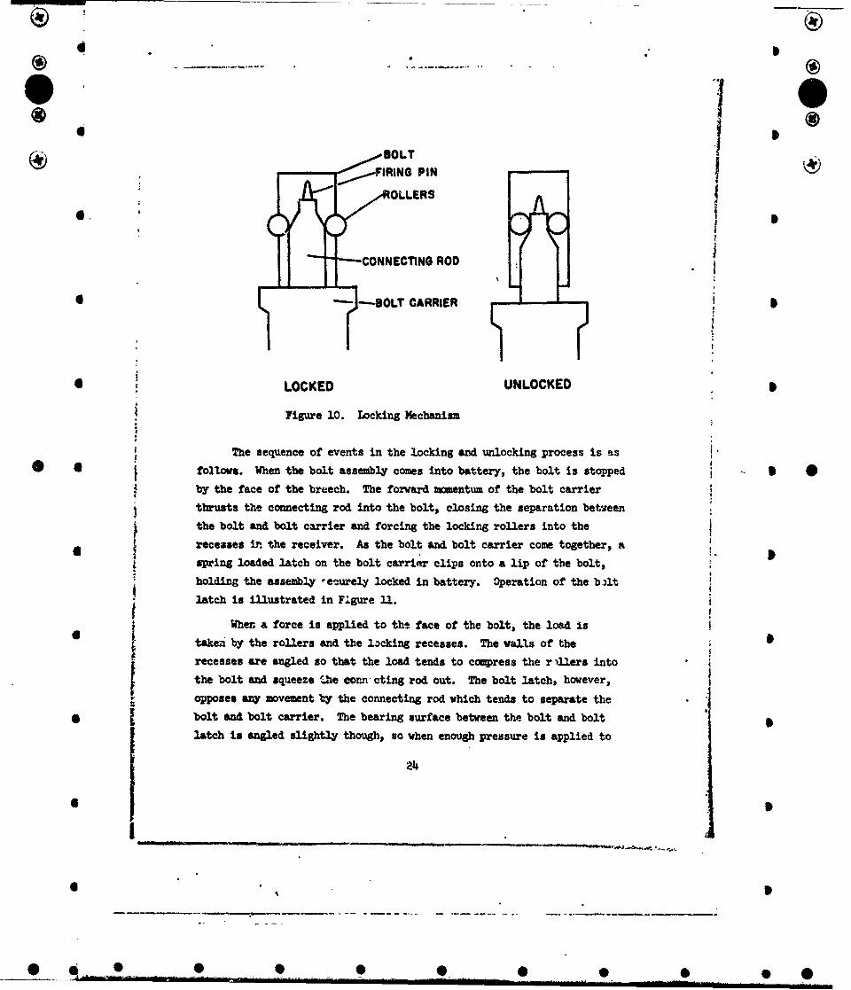
contains the firing pin.The Locking and Unlocking Process and the Associated Forces Besides
connecting the bolt and bolt carrier, the connecting rod implements
locking and unlocking. The ramp surfaces on the front of the connecting
rod bear on the locking rollers such that when the rod is pressed into
the bolt, the rollers are forced to protrude. Conversely, when therollers are compressed into the bolt, the rod is squeezed out, separating
the bolt and bolt carrier. The locking mechanism is shown in Figure 10.
21
SI4
0 4
4 AM 0 0 0 0 0 * 0

4 * I® 0
K 10 6I'
0 I 6* S I
0
I 0
.� 2 r.CD*10 * I 6
I- o 0o aC �.
o 4�1 hi0
m 04 @1 �*. 1 6
I. 2 hi u 0�
hi Z* 4 0� o= - -
-hi �21C
@4 E I S0I
I - £2 4-
* U* 0 E* I ,e�
4 - Z 0* I o a-hi 2o 5aU
*
Ii� .1
* 0
p B p B I I I0 4 *1 - 0
* I (NIt LN3K3�IV1dSIO
22
* I 0
* 0 0 0 0 0 0 0 * *
@0 In
)0
M* 19 t 0w ld a
I- z
z z
- 0
ol 4 0
2 0
.1k-
V -~ 0
(N IC "30 lg S
d -
* 1.
SOLTPI
OLLERS
-- CONNECTING ROD
* " ~-B-OLT CARRIER
I|
*LOCKED UNLOCKED
Figure 10. Locking Mechanism
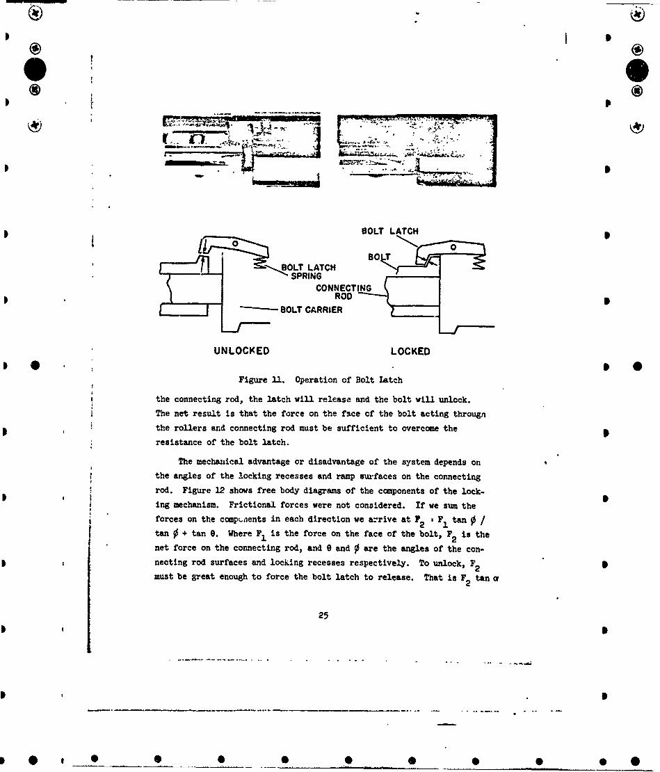
* The sequence of events in the locking and unlocking process is as I"
follows. When the bolt assembly comes into battery, the bolt is stopped I *by the face of the breech. The forward momentum of the bolt carrier
thrusts the connecting rod into the bolt, closing the separation between
the bolt and bolt carrier and forcing the locking rollers into the
* recesses i. the receiver. As the bolt and bolt carrier come together, a
spring loaded latch on the bolt carrier clips onto a lip of the bolt,
"holding the assembly eeurely locked in battery. Operation of the b~lt
3 latch is illustrated in Figure ii..
When a force is applied to the face of the bolt, the load is* itaken by the rollers and the lacking recesses. The walls of the
recesses are angled so that the load tends to compress the r illers into
the bolt and squeeze 1.he corn cting rod out. The bolt latch, however,
opposes any movement by the connecting rod which tends to separate the
* 1 bolt and bolt carrier. The bearing surface between the bolt and bolt
latch Is angled slightly though, so when enough pressure is applied to
24
* S
! ________
6 ¶ •
jo
0 0
® 0 T
13OLT LATTCH
/ ~SPRING ,
\ CONNECTING
I I • SOLT CARRIER
UNLOCKED LOCKED
I fAI' •~,
Figue 31. Operation of Bolt Latch
i ~the connecting rod, the latch wil.l release and the bolt wil.l unlock.
S~The net result is that the force on the face of the bolt acting throughS~the rollers and connecting rod must be sufficient to overcome the
resistance of the bolt latch.
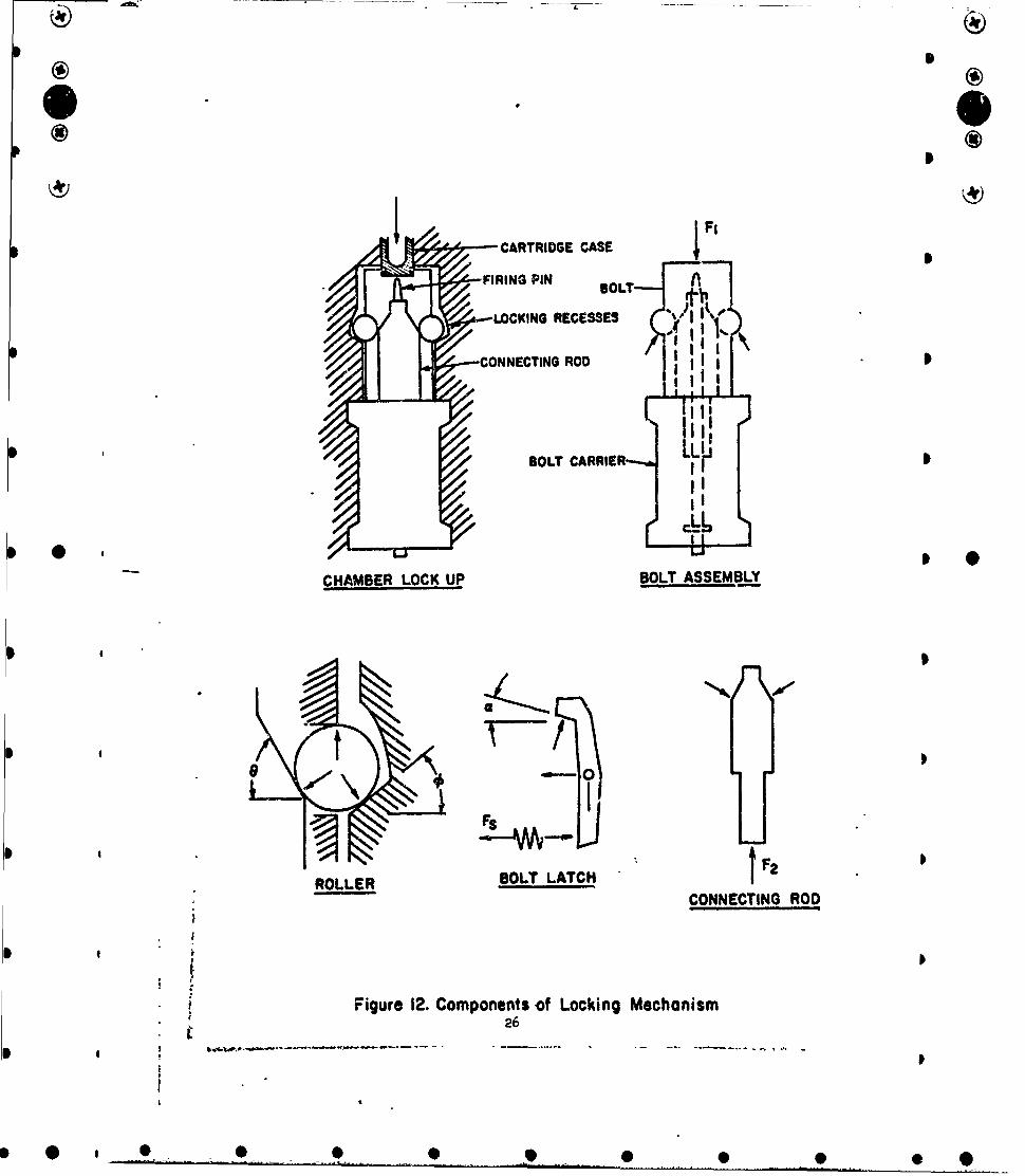
The mechanical advantage or disadvantage of the system depends on
the angles of the locking recesses and ramp s~urfaces on the connecting
rod. Figure 12 shows free body diagrams of the components of the lock-
ing mechanism. Frictional forces were not considered. If we sum the
forces on the compcnents in each direction we arrive at 7• 2 Fl tan /tan 0 + tan 0. Where F, is the force on the face of the bolt, F 2 is the
net force on the connecting rod, and 0 and 0 are the angles of the con-
necting rod surfaces and locking recesses respectively. To unlock, F2must be great enough to force the bolt latch to release. That is F 2 tan c
2LA
q) a •OO0
®I
O 0
CARTRIDGE CASE Fi
OFIRING PIN oLT
LOCKING RECESSES j1 -
CONNECTING ROD I /S•P<JI I - I
"BOLT CARRIER LLm.•S; II
•II
CHAMBER LOCK UP BOLT ASSEMBLY
* P
ROLESOLT LATCH F
,CONNECTING ROD
)N
*Figure 12. Components of Locking Mechanism
; 26 -0
LXii 5
* I
* i Figre12 Copoet•o Lokn Mechanis
* ®
I
must be larger than Fs, where F is the force applied by the bolt latch
spring, and a is the angle on the lip of the bolt latch.
The angle 9 measured 60°0 on each of the weapons tested. TheJ
angle 0 could not be measured accurately but was between 300 and 400.0 0
The angle ot was approximately 300. If we assume 0 to be 35 , then
F2 = F1 (0.288). Thus if F2 is 50 pounds, then F1 must be 174 poundsto uin.ock the bolt.
Experimental values for F, and F2 were determined with an Instron
Testing Machine. Force F2 was determined by latching the bolt and2lbolt carrier together in the lock position and recording the force
required to pull them apart in the Instron Testing Machine. Force FP
was determined by locking the bolt assembly in the receiver without the
drive spring and recording the force required to unlock the assembly by
pushing on the face of the bolt with a rod in the bore. The forces
obtained a.-e shown below.
0-3 Weapons Cm)
5.56mnm (newer) 331 89
5.5.6= (worn') 166 50
4 NOTE: F1 ia the force required on the face of the bolt to release the
locking mechanism, lb.
F2 is the force required on the connecting rod to release the
locking mechanism, lb.
The variation In F1 and F2 was caused by wear on the lip dthe
bolt latch and difference in the strength of the bolt latch spring.
In actual operation the load on the face of the bolt exceeds 3000
pounds at the peak chamber pressure. The bolt is not completely
ualocked, however, until the pressure in the chamber has past its peak,
because of the inertia and friction of the mecnanism. A lower value of
F2 alJows earlier unlocking, resulting in a higher rate of fire because
the velocity of the bolt assembly is increased moving out of battery.
* 4 27
4#
O I
* 4Q i
Bolt Assembly Gap When the bolt assembly is locked in battery,
there is a slight gap between the bolt and bolt =arrier. The gap
* 4 measured 0.014 inch on the newer 5.56=m weapon but only 0.008 inch on
the worn 5.56amm weapon because wear in the locking recesses allcwr
more roller protrusion and more connecting rod penetration. The 7.62m
weapon has a gap of 0.012 inch. This gap is designed to keep the bolt and
bolt carrier from impacting with each other. If they were allowed to
* impact, two problems would arise. First, on coming into battery the
bolt carrier would boix-ce off the bolt and might unlock the bolt assembly.
Secondly, the initial torce on the face of the bolt would be transmi.tted
direc #3ly to the bolt carrier rather than through the rollers and con-
* 4 necting rod.
Special Features Some special features of the G-3 system are an
open bolt catch and a damping device in the bolt assembly found only on
the 5.56m weapon and a fluted chamber and an unusual charging assembly
* * * found on both the 5.56 and 7.62na weapons. * *The open bolt catch is designed to hold the bolt assembly back
after the last round of a magazine is fired. This notifies the firer
that the magazine is empty and makes charging easier after the next
* magazine is inserted. The gun is charged by simplv pushing the bolt
release, located Just forward of the trigger.
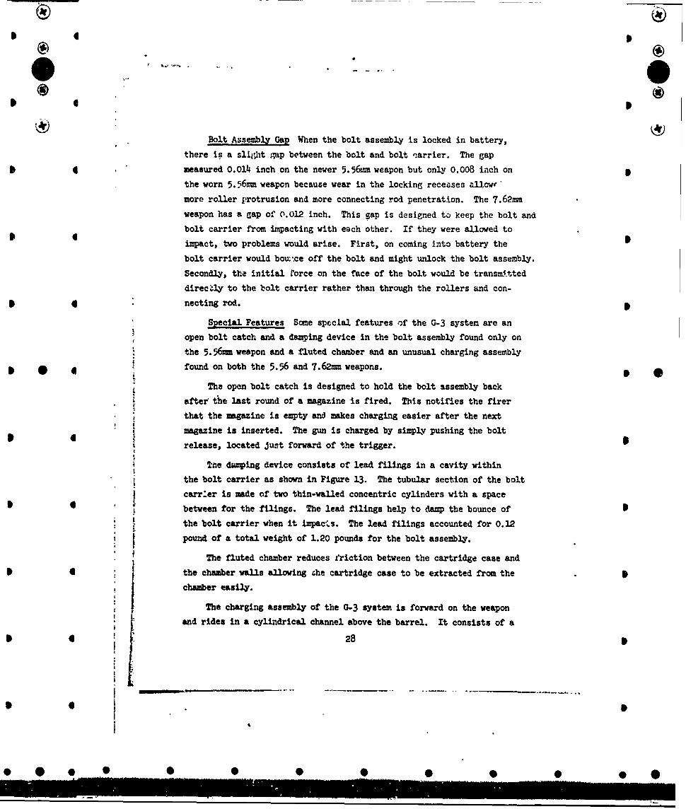
UTe daping device consists of lead filings in a cavity within
the bolt carrier as shown in Figure 13. The tubular section of the bolt
carrier is made of two thin-walled concentric cylinders with a space
* 4 between for the filings. The lead filings help to damp the bounce of
the bolt carrier when it impacLs. The lead filings accounted for 0.12
pound of a total weight of 1.20 pounds for the bolt assembly.
The fluted chamber reduces friction between the cartridge case and
* the chamber walls allowing the cartridge case to be extracted from the
j chamber easily.
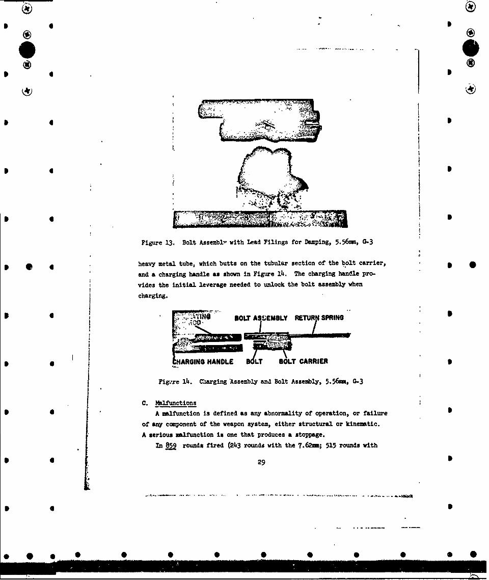
The charging assembly of the G-3 system is forward on the weapon
and rides in a cylindrical channel above the barrel. It consists of a
* t 28
I -
* I S
* *
* 0Cie
I I
* ,*7R'
ilk
Figure 13. Bolt Assembld with Lead Filings for Damping, 5. 56mm, G-3
* * * heavy metal tube, which butts on the tubular section of the b.olt carrier, * *and a charging handle as shown in Figure 14. The charging handle pro-
vides the initial leverage needed to unlock the bolt assembly when
charging.
,.BOLT AS'EMBLY RETUR PRING
* 4ARGING HANDLE LT BOLT CARRIER
Figvxe 14. CMarging Assembly and Bolt Assembly, 5. m, &-3
C. Malfunctions
SA malfunction is defined as any abnormality of operation, or failure
of any component of the weapon system, either structural or kinematic.
A serious malfunction is one that produces a stoppage.
In §1 rounds fired (243 rounds with the 7.-62; 515 rounds with
• 6 29 S
*.t. e.Q.- .. .. . .O.. .. tS..,. - .. a-a4S

. . (
the newer 5.56mm; 101 rounds with the worn 5.56mm) there were no
malfunctions that produced stoppages except those which were induced by
modifying the mechanism. A table of malfunctions is given below, fol-
lowed by an explanation of each type of malfunction. 6
Table V. MlfunctionsNo. of No. of
G-3 Weapons Condition Malfunction Malfunc. Stoppages
5.56mm (newer) Oiled Failvre of open bolt catch 10 0 I 6
5.56mm (newer) Dry Failure of open bolt catch 2 0
5.56mm (worn) Oiled Failure of open bolt catch 3 0
5.56=m (newer) Dry Short travel 4 0
7.62m Dry Excessive delay 5 0
7.62=m Oiled Excessive delay 3 0
S5.56mm (newer) Oiled Broken drive spring washer 1 0
5.56mm (worn) Oiled Broken drive spring washer 2 0
5.56mm (worn) Oiled Failure to eject 2 2w/modified mech) * * *
Failure of Open Bolt Catch The open bolt catch failed to operate
15 times oul. of roughly 80 crancen. There were no instances of the
open bolt catch working before the last round of a magazi, e was fired Ihowever, so the malfunction did not cause a stoppage. The open bolt
* catch, which is part of the trigger mechanism, is activated when the
magazine follower trips a sear which allows the bolt catch to spring
into position. The sear is not always tripped off because of the
lack of guidance of the magazine follower.
*�Short Travel A cycle was defined to have short travel if the bolt 6
assembly did not reach the backplate after firing the round. To carry
* out all the functions of a cycle the bolt assembly must travel at least
3.58 inches from battery in the 5.56mm weapon. The shortest travel
recorded was 5.60 inches. Four short travels occurrel during the test, .
, all with the newer 5.56mm weapon in the unlubricated condition. The
!; stronger spring in the locking mechanism of the newer rifle, the lack of
lubrication, and the softness of the gun mount combined to cause the
30
• • • • ° • •.•......
0 0
Cie)0 0 4
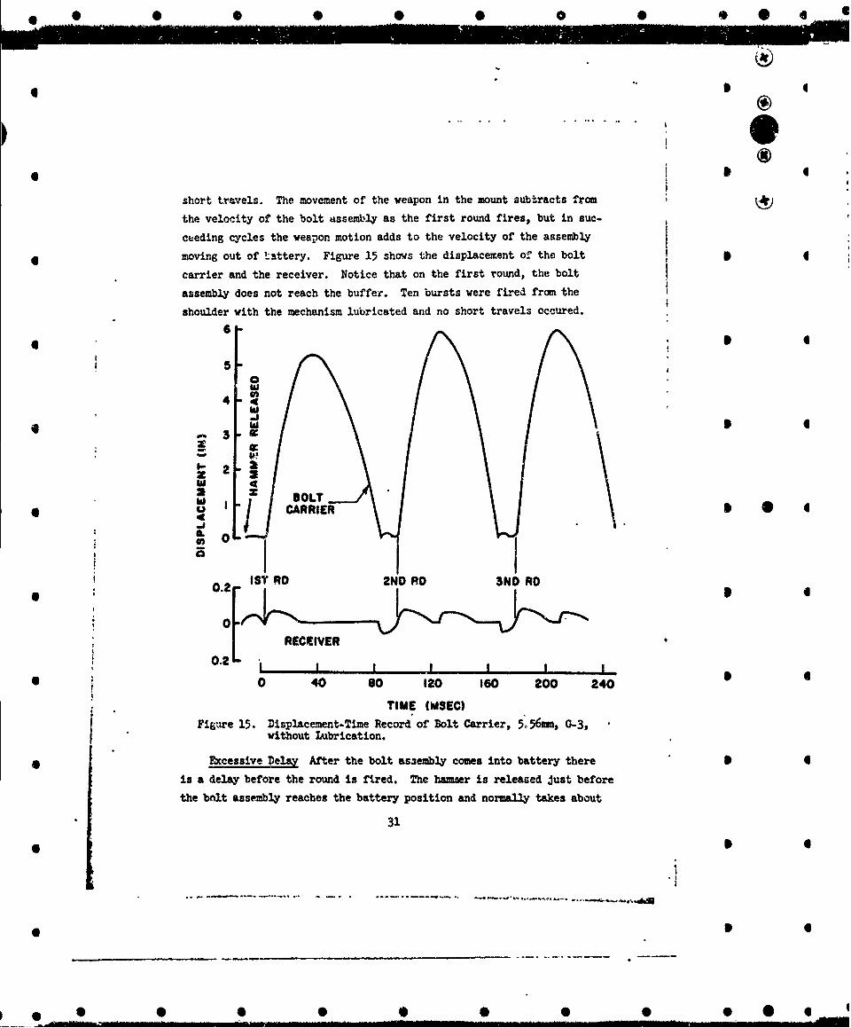
short travels. The movement of the weapon in the mount subtracts from
the velocity of the bolt assembly as the first round fires, but in suc-
ceeding cycles the weapon motion adds to the velocity of the assembly
* moving out of tattery. Figure 15 shows the displacement of the bolt
carrier and the receiver. Notice that on the first round, the bolt
assembly does not reach the buffer. Ten bursts were fired from the
shoulder with the mechanism lubricated and no short travels occured.
6
5-0hi
4
0-3
S2
2 BOLT
.- 4CARRIER0jIL OLi STRD 2ND RD N RD
02 [RECEIVER*0 40 8o 120 160 200 240
TIME (MSEC)
Figure 15. Displacement-Time Record of Bolt Carrier, 5*.56nmm, G-3,without Lubrication.
S~Excessive Delay After the bolt as-embly comes into battery there •
is a delay before the round is fired. The hanser is released just before
the bolt assembly reaches the battery position and normally takes about
31
6 S!
* 0 0 0 0 0 4) 0 0 0 0 •
) 4
I.I
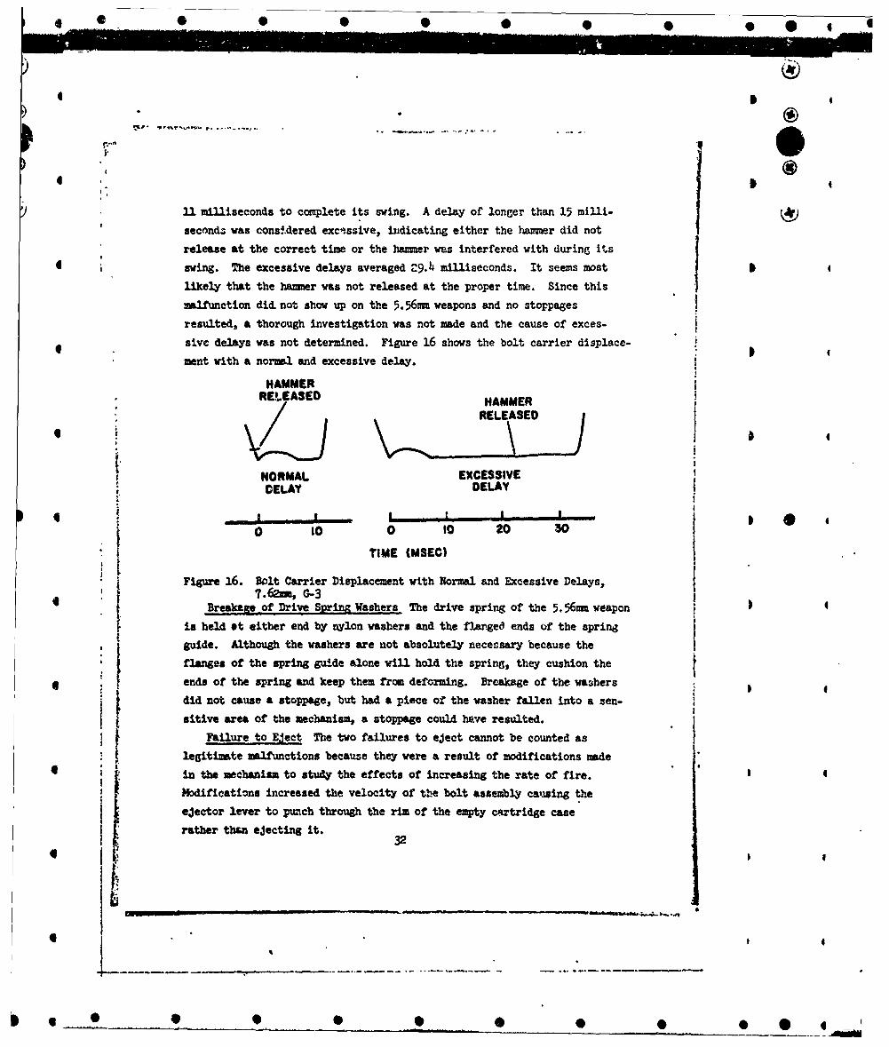
11 milliseconds to complete its swing. A delay of longer than 15 milli- Iu?seconda was considered excessive, indicating either the hammer did not
release at the correct time or the hammer was interfered with during Its
4 swing. The excessive delays averaged C-9.4 milliseconds. It seems most
likely that the hamner was not released at the proper time. Since this
malfunction did not show up on the 5.56ms weapons and no stoppages
resulted, a thorough investigation was not made and the cause of exces-
sive delays was not determined. Figure 16 shows the bolt carrier displace-
ment with a normal and excessive delay.
HAMMERREV.EASED HAMMER
1~ RELEASED
NORMAL EXCESSIVEDELAY DELAY
* a , ____,______________
0 0 0 10 20 30
• TIME (MSEC)ItFigure 16. Bolt Carrier Displacement with Normal and Excessive Delays,
7.62ams G-3Breakage of Drive Spring Washers The drive spring of the 5.56nm weapon
is held ot either end by nylon washers and the flarged ends of the spring
guide. Although the washers are not absolutely necessary because the
flanges of the spring guide alone will hold the spring, they cushion the* ends of the spring and keep them from deforming. Breakage of the washers
did not cause a stoppage, but had a piece of the washer fallen into a sen-
sitive area of the mechanism, a stoppage could have resulted.Failure to Eject The two failures to eject cannot be counted as
legitimate malfunctions because they were a result of modifications made
* in the mechanism to study the effects of increasing the rate of fire. 4
Modifications increased the velocity of tbe bolt assembly causing the
ejector lever to punch through the rim of the empty cnrtridge case
rather than ejecting it.32
* .. ..
1
It)
D. Firing Data
In order to investigate possible problem areas, much of the firing
of the 5.56mm weapon was done with modifications in the mechanism. The Imodifications included removing the lead filings from the bolt assembly,
adding a steel shim between the bolt and bolt carrier, and interchanging
parts from the newer and worn weapons. The lead filings were removed
for two reason3; to reduce the mass of the bolt assembly and hence
increase the rate of fire, and to increase the bounce of the bolt carrier
upon impact by eliminating the damping. A shim was used between the bolt
and bolt carrier to ease unlocking and to further increase the bounce of
the bolt carrier upon impact. The shim eliminates the gap between the
bolt and bolt carrier so that the initial motion of the bolt after firing
is transmitted directly to the bolt carrier through the shim rather than
through the rollers and connecting rod. The worn and newer bolt assem-
blies were used interchangeably with each of the 5.56mm receivers to
determine which components are subJect, to extreme wear, and what effect
this wear has on functioning. In some instances all of these modifica- 0tions were used simultaneously.
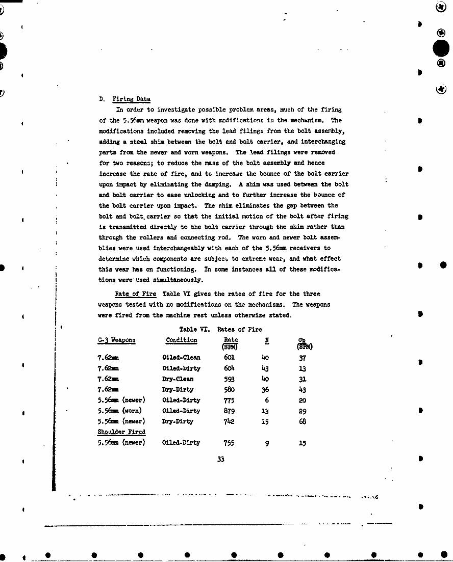
Rate of Fire Table VI gives the rates of fire for the three
weapons tested with no modifications on the mechanisms. The weapons
were fired from the machine rest unless otherwise stated.
Table VI. Rates of Fire
G-3 Weapons Condition Rate N •r
7.62mm Oiled-Clean 601 40 377.62mm Oiled-DIrty 604 43 13
7.62mm Dry-Clean 593 40 317.62mm Dry-Dirty 580 36 435.56em (newer) Oiled-Dirty 775 6 20
5.56Mu (worn) Oiled-Dirty 879 13 29 •5.56m (newer) Dry-Dirty 7142 i5 68Shoulder Fired
5.56(= (newer) Oiled-Dirty 755 9 15
33 •

4 ®
I I,
NOTE: N is the number of rounds in the statistical sample
c R is the standard deviation in rate of fire, shots per minute
First round cycles were generally slower than cycles of succeeding
4 rounds in a burst. The first rcund cycles of the newer 5.5.;m weapon, 4
when fired dry, were especially slow because of a number of short bolt
assembly travels. This is attributed to reduced crush-up of the car-
tridge case on the first round because it is chambered only with the
energ of the driving spring from the sear position. As a result, the
clearances in the locking rollers are reduced causing unlocking to be more
difficult and the velocity of the bolt in recoil to be cl-area&Led. Rates
of fire of first cycles and succeeding cycles are given in Table VII.
Ratas are given in shots per minute (SPM).
Table VII. Rates of Fire with Modifications 5C=erison of Initial & Succeeding Cycles
G,-3 Weapon Lubrication First Cycle Succeeding CyclesRat-e N a Rate N ar(sem) (SD) (Sm) (;14)
S.4 Tuo2 Vzed 596 9 20 60o 18 26 •7.6&h Dry 575 8 21 585 16 255.% (never) Oiled 757 2 785 45.56m (never) Dry 664 5 28 788 10 16
5.5 (worn) Oiled 862 6 20 894 7 294 4
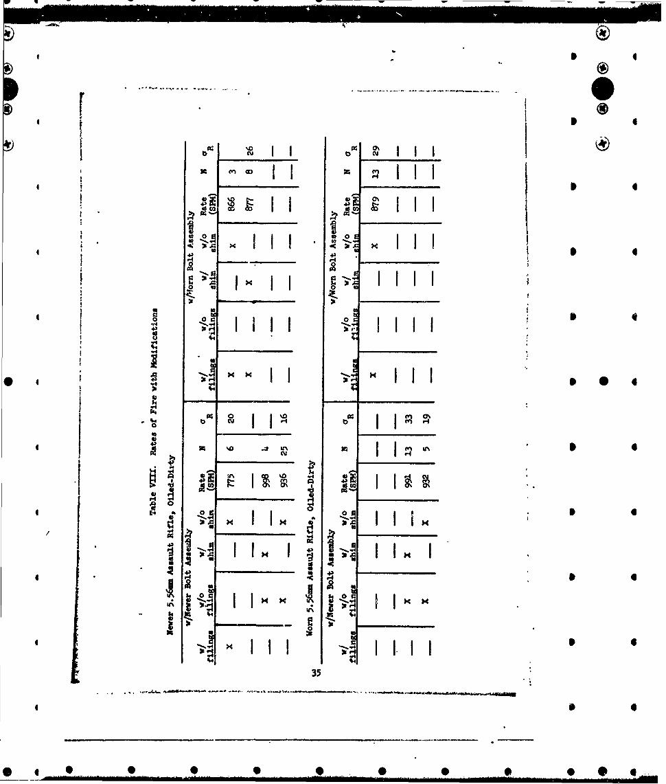
The mechanism modifications made on the two 5.5 6 nu weapons affected
their rates considerably. Table VIII shows the rates of fire obtainedunder various conditions. Frcm Table VIII we see that substituting. tbe
worn bolt assembly in the newer weapon increases the rate of fire from775 to 866 shots per minute. The increase was expected because the
locking mechanism of the worn bolt assembly is much weaker than that of
the newer one, as explained earlier.
Removing lead filings from the newer bolt assembly changed its
w4gbit from 1.20 to 1.08 pounds. The reduction in weight increaced the 4
rate of fire from 775 to 936 shots per minute.
3.4
4 4
cull
'ý Q x I I 40 , 'O ' I
0 a
r . .
* 'a4
4 ~~~~~0 l i .eIl 4
''II
U * u
* 4) xli p4co
I *~ x
V4
*~ -- - A*
$4
* -35
_AIm

i)
The wear of the receiver did not seem to affect functioning appre-ciabl~y. For instance, -when the newer bolt assably was used in the worn
weapon the rate of fire was comparable to that with the newer bolt assem-b2.y in the newer veapon.
The shim, which was 0.018 inch thick, caused the rate of fire toincrease only 10 to 50 shots per minute.
Bolt Assembly Velocity The velocity of the bolt assembly and rate
of fire are proportional. That is, the faster the bolt assembly movesthrough the cycle, the higher the rate of fire will be. The velocity 6of the bolt assembly must be within certain bounds however. Forinstance, If the velocity of the bolt assembly is too high when itreaches the ejector lever the empty caae m*iy be punctured rather thanejected. On the other hand if the velocity lust out of battery is toolo a short travel my result. Velocities of the bolt assembly areshown in Table TX under different firing conditions. The values given
represent the maxium velocity just out of battery.
4 . Table UX. Bolt Assembly VelocityG-3 leuons Iubrication Condition Vlps) (
7.-62N Olled Fired from Machine Rest 24.2 20 0.95.56 (never) Oiled Fired from Machine Rest
S5.3( (worn) Oiled Fired from Machine Rest 25.0 6 1.15.56 (never) Oiled Fired from Shoulder 24.6 9 1.2
5.56M (newer) Dry Short Bolt Travel 22.0 45.56 (orn) Oiled Failed to Eject 39.7 2
NC=: av is the standard deviation in velocity, ft per sec (frqS)
Figure 17 sho-s a plot of the displacement and velocity of the boltassembly versus 4:•e, for a typical cycle of the 5.56bc
Bolt Carrier Bounce Bolt carrier bounce is of interest because itj could conceivably cause failure to fire If excessive. As the bolt* assembly comes into battery the bolt hits the face of the breech and
rebounds. Before the bolt can bounce very far however, the in.-ceingj 36
• • C 0••. , ,
* 4

0 g I ® 4
0 0
* 4 4
1*3
0 0 40 Gos
110
* AI ~I
0
> 0 20 40 60 so
TIE TIM MSEC) a a
-to• -I0•
Figure 17. Displacement and Velocity of Solt Carrier 5.56 MM G-3.0 2 4 6 6
-P0
® '®
* U
o
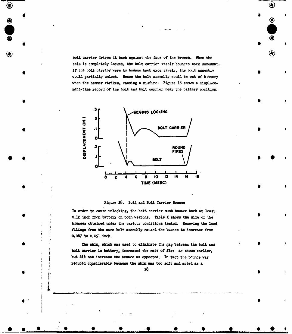
bolt carrier d3.ives it back against the face of the breech. When the
bolt is cciplate•y locked, the bolt carrier itself bounces back somewhat.
If the bolt carrLr were to bounce baek exce:,sively, the bolt assembly
would partially unlock. Hence the bolt assembly could be out of b .tterl
when the hazer Etrikes, causing a misfire. FiGure 18 shows a displace-
ment-time record of the bolt and bolt carrier near the battery position.
4 S
•.3- EGINS LOCKING
2i
4 - .1 BOLT CARRIERz
O\, RON
II RE,
0 4 I I- I I i I I0
0 2 4 6 6 o0 12 14 I 18
TIME (MSEC)
Figure 18. Bolt and Bolt Carrier Bounce
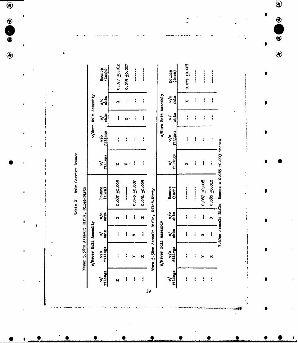
In order to cause unlocking, the bolt carrier must bounce back at least
4 : 0.12 inch from battery on both weapons. Table X shows the size of the 5
bounces obtained under the various conditicns tested. Removing the lead
filinas frým the worn bolt assembly caused the bounce to increase from
0.067 to 0.091 inch.
* The shim, which was used to eliminate the gap between the bolt and
bolt carrier in battery, increased the rate of fire as shown earlier,
but did not increase the bounce as expected. In fact the bounce was
reduced copsiderably because the shim was too soft and acted as a6 38 .3
I
_ * * 0 0I
go C;0.s 0
0 0 0
00
4- ý 815 40c (4*S I ~ 3.
4134
0 02
*~~U XX, NS
0) u. 0*1 *
0'00 0~0 p44
aDOa
-N 00
so 4 U 4.1
I SN S ~ 39

I
* ji A I
cushion between the bolt and bolt carrier.
Recoil Impulse The recoil impulse of the 7. 6 21m and the newer
5. 56mm weapons was measured in the ballistic pendulum. As shown in
Table XI, the recoil impulse varies with the lot of ammunition used.
Table XI. Recoil Impulse
G-3 Weapons Condition J N o j Lot of Ammolb sec. lb sec.
7.62=u w/ muzzle device 2.638 5 0.0199 WCC-6OQ7
7.62M w/o muzzle device 2.595 6 0.0107 WCc-6007
5.56um (never) w/ muzzle device 1.269 6 0.0140 &1 5072
5.56mm (newer) w/o muzzle device 1.206 6 0.0081 RA 5072
5.56mm (newer) w/ muzzle device 1.328 8 0.0088 RA 5089
5.56am (never) w/o muzzle device 1.272 6 0.0010 RA 5089
NOTE: J is the recoil impulse, lb secaj is the standard deviation in mcsured re3coil impulse, lb sec
Muzzle Vibration Muzzle vibration was not appreciable. The* muzzle reached its maximum amplitude after the third round of a burst. I
The displacement-time record of vertical muzzle vibration shown in
Figure 19 wva obtained with the never 5.56m weapon.
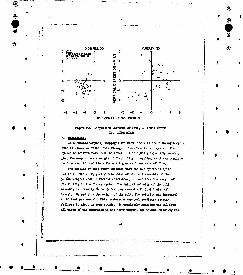
Projectile Dispersion Targets were placed 63 feet from the muzzle.
Figure 20 shows the ccqpaWative dispersion patterns obtained when firing
five, ten-round bursts from both the 7.62mm and the newer 5.56mm weapon.
Projectile Velocity Projectile velocities at the muzzle are givenin Table XII for the 7.62=m and the newer 5.562m weapons. Values are
given witn and without muzzle devices.
Table XII. Projectile Velocity
G-3 Weapons VM N CJ Lot OfAMMofps fps
7.62M2709 8 33 WCC-60077.62M 2689 12 35 RA 50555.56um (newer) 3021 5 42 RA 50725.56mm tnever) 2998 14 61 RA 6089NOTE: VM is the muzzle velocity of the projectile, ft per sec (fps)
4o
* e * I

00
0o
I as
0 ~CP
9Lw 0
00*N .
H3 v6~j
4®44
• a
5'56 MM, G3 7.62 MM, G3; FIRST ROUNDS OF BURSTS
ARE SUPERIMPOSED ATTHE O•IGIN.
2 %
zaI Z I " .,, • .
gas
e~*~ a
S - . .*.
-2 * -2 •4>
JI-3 -2 -I 0 I -3 -2 -I 0 I 2 3
HORIZONTAL DISPERSION-MILS
* * . Figure 20. Dispersion Patterns of Five, 10 Round Bursts! ~ ~IV. DMIscssIoN
* , A. ReliabilityIn automatic weapons, stoppages are most l!kely to occur during a cycle
that is slower or faster than average. Therefore it is important thatcycles be uniform from round to round. It is equally important, however,
that the weapon have a margin of flexibility in cycling so it can continue* to fire even if conditions force a higher or lower rate of fire.
The results of this study indicate that the G-3 system is quite; reliable. Table IX, giving velocities of the bolt assembly of the
5.56mi weapons under different conditions, demonstrates the margin of2flexibility in the firing cycle. The initial velocity of th-• bolt
assembly is normally 24 to 25 feet per second with 5.83 inches of
* travel. By reducing the weight of the bolt, the velocity was increased
I to 40 feet per second. This produced a marginal condition causing, failures to eject on some rounds. By copletely removing the oil from
all parts of the mechanism in the newer weapon, the initial velocity was
4• ! 42
6
II
"" 9 *

4
reduced to a minimum of 22 feet per second with s minimum travel of
5.60 inches. Only 3.60 inches of travel is required for feeding and
* stripping indicating the weapon will function with a bolt assembly
velocity considerably less than 22 feet per second. Compared to other
automatic weapons, the variations that can be tolerated in the cycling
of these weapons is extremely large. The weapons should continue to
' fire wnder adverse environmental conditions and with large variationsin the interior ballistic performance of the ammunition.
The weapons fire equally well whether dirty or clean as illustrated
by the rates of fire given in Table VII. This is significant since the
mechanisms become heavily coated with carbon after only a few rounds
*I •are fired, because of the blowback operation and the fluted chamber. A
lack of lubrication reduces the rate of fire only 10 - 20 shots per
minute.
B. Performance
* * * The relatively short barrel of the G-3 Assault Rifle limits the * *projectile velocity that can be obtained from the 5.56.a cartridge.The 5.56me, G-3 for instance has a barrel length of about 16 inches
which is approximately three inches less than that of the W16.I C. Bolt Latch
The bolt latch, which locks the bolt and bolt carrier together in
battery, is a key component in the functioning of the mechanism. As thelip of the bolt latch wears and the bolt latch spring becomes weaker,unlocking becomes easier and the rate of fire increases.
6 D. Bolt-Bolt Carrier Gap
The gap between the bolt and bolt -arrier decreases with wear. Thegap measured 0.014 inch on the virtually new 5.56-u weapon and 0.008
inch on the worn 5.56mm weapon. This variation had little or no* effect on functioning. If the gap were eliminated altogether however,
the unlocking process would be altered, as described earlier.
E. Possible ChangesThe open bolt catch should be redesigned. As it is now the magazine
143
I 0
0) - -
0 0 0 0 0
follower does not always make contact with the sear and release the catch. JThe charging handle might also be changed. It tends to bind when
charging, especially with the worn 5.56Mm weapon.
F. Damping Device
The damping device in the bolt assembly seems to work quite well. .
It reduces the bounce of the bolt carrier considerably. The bounce did
not reach a serious level though, even when the lead filings were removed
from the bolt assembly.
G. Weigh
Both the 7.62mm and the 5.56mm weapo.as are slightly heavy when
coapared to similar weapons as can be seen in the table of weights. The
weight could be reduced by making the stock and foregrip out of fiberglas
and perhaps making the trigger mechanism out of aluminum. A simpler
charging assembly might also reduce the weight. :
4 44
i
I
I ,D
i..
I
D 16-F
. 0b 9 O 0 0• 0) *
I ® 4
REEREfCEIS
1. H. P. Gay, Displacement-Time Recorder. BRL Report No. 610, June 1946.
2. H. P. Gay, Notes on Techniques and Apparatus for Investigating theEffects of Recoil and the Stability of Mounts for Small Arms Weapons. 4BRL Memorandum Report No. 955, December 1955.
ft
* 45
* 4
* 0
* 4
6a
4 •Cie)
*tS......• y •~~~_nclassified .- n,.t ! )
Security CI..usftcett~e
DOCUMENT CONTROL DATA - & 0tb1"ewp.iMff? s giJwn Of H00g. IN0 *g .. rNm and Woovap Ain0ta.II e Is.. on. " OR"s. eAae ff Mpeef t. et...iedj)
U.S. Army Aberdeen Research and Development Center UnclassifiedBallistic Research Laboratories so. GRoUPAberdeen Proving Ground, Maryland
a. 09POAT TITLE
A COMPARATIVE EVALUATION OF THE 7.62MM AND 5.56MM, G-3 ASSAULT RIFLES
4. OXICNIPIVE NOT9 MPG~ *1W Vimd Awftv dwa)
i. A£vNORIUI (F/.0008. ARE" fw;& f ame)
Thomas E. Carlson, David A. Golm
VI RaEPORT DATE T& TOTAL "0. oP PAOSA |7T. NO. Or RiPeS
January 1969 48 2=2 ONTRIACT OR GRANT 00. or. 01106ff*aTO7WS REPORT ."iWUSgRI&
6. PROJEcT N. RDT&L IW523801A304' Memorandum Report No. 19534 D
6. 91. OT763 REPORT NOI4 (AVy M• * maeta besp liefpimIWe "w
SI nlb. urm~otls *7*7*063?T
This document is subject to special export controls and each transmittal to foreigngovernments or foreign nationiLs may be made only with prior approval of CommandingOfficer, U.S. Army Aberdeen Research and Development Center, Aberdeen Proving Ground, * *
O&10 T.P1IENARV NoTvs aI. SPONSOR Il MiLItARV ACTIVITY
U.S. Army Materiel CommandI/Washington, D.C. 20315
09. VqGlltRAC T
A test was conducted with 7.62mm and 5.56mm, G-3 Assualt Rifles to evaluate and com-4 pare the kinematics, reliability, safety features, physical characteristics, recoil
impulse, rates of fire, proje•tile velocities, muzzle motion and accuracy of theweapons. No serious problems were detected during the tests and the reliability ofthe weapons was comparable.
tt
4S
F - -- -) -, -'eJ 7 ..r----N:--- ----. II Ll•-•.i -O11ia~ - •il
pow 473P 1Unclassi" ed
.V1 Cum-Ace"
4
KEY 504OU oAWN £ t.INK a LAOKw Cw
Rifle, 5.56mm and 7.62mm, G-3Assualt Rifle, 0-3Kinematics, 5.5 6mm and 7.62mm, C-3Recoil impulse, G-3Rate of fire, G-3 rifleMuzzle motion, G-3 rifleMuzzle velocity, G-3 riflePhysical characteristics, 0-3 rifleAccuracy, G-3 rifle
U a f
I 4 S
Unclassified 5