UN-TR- 10-001-NP UnuStar - nrc.gov · UnuStar NUCLEAR ENERGY UN-TR- 10-001-NP Revision: 0 UniStar...
153
UnuStar NUCLEAR ENERGY UN-TR- 10-001-NP Revision: 0 UniStar Topical Report for the Use of High Density Polyethylene (HDPE) Pipe in ASME Section III, Class 3, Seismic Category I, Safety- Related Buried Water Pipe Applications NON-PROPRIETARY
Transcript of UN-TR- 10-001-NP UnuStar - nrc.gov · UnuStar NUCLEAR ENERGY UN-TR- 10-001-NP Revision: 0 UniStar...

UnuStarNUCLEAR ENERGY
UN-TR- 10-001-NPRevision: 0
UniStar Topical Report for the Use of HighDensity Polyethylene (HDPE) Pipe in ASMESection III, Class 3, Seismic Category I, Safety-Related Buried Water Pipe Applications
NON-PROPRIETARY
UmiStar-NUCLEAR ENERGY UN-TR- 10-001-NP
UniStar Topical Report for the Use of High Density Polyethylene (HDPE) Pipe in ASME Revision:0Section III, Class 3, Seismic Category I, Safety Related Buried Water Pipe Applications
Description of Revisions
i

UniStar-NUCLEAR ENERGY UJN-TR-10-001-NP
UniStar Topical Report for the Use of High Density Polyethylene (HDPE) Pipe in ASME Revision:0Section Il, Class 3, Seismic Category I, Safety Related Buried Water Pipe Applications
ABSTRACT
This Topical Report (TR) presents code compliance, acceptance criteria, analysis methods,and modeling techniques for the use of High Density Polyethylene (HDPE) pipe in ASMESection III, Division 1, Class 3, Seismic Category I, buried service and cooling water pipingfor the U.S. EPRTM to be built by UniStar Nuclear Energy or its partners. This TopicalReport also includes the requirements for the procurement, fabrication, installation,examination, and testing of the piping.
Section 2.0 identifies industry codes and standards applicable to the design, analysis,material specification, fabrication, installation, inspection, and testing of buried HDPEpiping.
Section 3.0 presents the HDPE piping stress analysis criteria and identifies the loaddefinitions and load combinations used in the qualification of buried HDPE piping. Thissection also discusses the HDPE piping design to address issues related to HDPE materialssuch as material properties, Design Factor, range of applicable pipe sizes, and designconditions (pressure and temperature).
Section 4.0 focuses on the seismic analysis methods. This section presents buried HDPEpiping requirements and soil-load interactions.
Section 5.0 presents pipe modeling techniques used for the qualification of HDPE piping.
Section 6.0 presents the HDPE pipe support design criteria for buried HDPE piping.
Section 7.0 provides installation requirements for buried HDPE piping.
Section 8.0 presents the inspection and test criteria applicable to the use of HDPE piping asdescribed in this TR. This section includes requirements to perform non-destructiveexaminations (NDE), and fusion machine operator qualifications.
Section 9.0 addresses design life; including predicted service life, design for elevatedtemperatures, and fatigue loading. This section demonstrates the ability for HDPE pipe tosafely operate for 60 years and beyond by use of the Rate Process Method (RPM).
Section 10.0 identifies Quality Control (QC) and Quality Assurance (QA) requirements.Material manufacturers, suppliers, fabricators and installers are required to maintain andimplement a Quality Assurance Program.
Section 11.0 identifies the requirements and guidelines that a licensee is responsible toinclude in a COL application for the U.S. EPRTM to be built by UniStar Nuclear Energy orits partners.
Section 12.0 summarizes and presents conclusions.
Section 13.0 lists references used for the development of this Topical Report.
This Topical Report demonstrates that HDPE 4710 piping is suitable for buried pipeapplications for a Design Pressure up to 200psig, a Design Temperature up to 140'F, and a60-year service life. Approval for HDPE piping identified herein is requested for a periodof 40 years, consistent with the license term of a Combined License.
ii

UniStarN U C L E 4 R F. N E A a Y LJN-TR-10-001-NP
UniStar Topical Report for the Use of High Density Polyethylene (HDPE) Pipe in ASME Revision:OSection 111, Class 3, Seismic Category 1, Safety Related Buried Water Pipe Applications
TABLE OF CONTENTS
1.0 INTRODUCTIO N ............................................................................................................. 1-1
1.1 Definitions ........................................................................................................................... 1-2
2.0 CODES AND STANDARDS ............................................................................................ 2-1
2.1 ASM E Boiler and Pressure Vessel Code ........................................................... ; ................ 2-12.2 ASTM Polyethylene (PE) M aterial Standards .................................................................... 2-12.3 Plastic Pipe Institute (PPI) .................................................................................................. 2-32.4 intem ational Standards Organization (ISO) ........................................................................ 2-3
3.0 PIPING STRESS ANALYSIS CRITERIA ..................................................................... 3-1
3.1 Piping Seism ic Classifications ............................................................................................ 3-13.2 Service Levels .......................................................................................................... .......... 3-13.3 Load Cases and Load Combinations ................................................................................... 3-23.4 Fatigue Evaluation .............................................................................................................. 3-63.5 Functional Capability .......................................................................................................... 3-63.6 M aterial Properties .............................................................................................................. 3-73.7 Nom enclature .................................................................................................................... 3-103.8 Hydrostatic Design Basis for Temperatures Over 140'F and Up To 160'F ..................... 3-133.9 Slow Crack Growth Resistance ......................................................................................... 3-133.10 Pressure Design of Pipe .................................................................................................... 3-133.11 Longitudinal Stress Design ............................................................................................... 3-193.12 Temperature Design .......................................................................................................... 3-203.13 Non-repeated Anchor M ovem ents .................................................................................... 3-213.14 Soil and Surcharge Loads ................................................................................................. 3-223.15 Seism ic Design - Seism ic Induced Stresses ..................................................................... 3-273.16 Flange Joint Evaluation ..................................................................................................... 3-27
4.0 PIPING ANALYSIS M ETH ODS .................................................................................... 4-1
4.1 Seism ic Analysis Input for Buried Piping ........................................................................... 4-14.2 Response Spectrum Seismic Analysis Method for the Combined System .......................... 4-34.3 Analysis Inputs .................................................................................................................... 4-44.4 HDPE to Steel Interface ...................................................................................................... 4-44.5 M odeling of PE Elbows ...................................................................................................... 4-54.6 Stress Intensification Factors (SIFs) ................................................................................... 4-54.7 Soil Springs ......................................................................................................................... 4-54.8 Analysis of the Above Ground M etal Piping ...................................................................... 4-64.9 Design Report (Stress Analysis Report) .............................................................................. 4-6
5.0 PIPING M ODELING TECH NIQUES ............................................................................ 5-1
5.1 M ethodology and Approach ................................................................................................ 5-15.2 Structural Boundaries .......................................................................................................... 5-15.3 Flexibility of M itered Elbow Fittings .................................................................................. 5-15.4 Soil Springs ......................................................................................................................... 5-15.5 Vertical Piping Runs ......................................................................................................... 5-10
6.0 PIPE SUPPORT DESIGN CRITERIA ........................................................................... 6-1
6.1 General ................................................................................................................................ 6-16.2 Tem porary Supports for Inspection .................................................................................... 6-16.3 Building Anchor M ovem ents .............................................................................................. 6-1
7.0 INSTALLATION REQUIREM ENTS ............................................................................ 7-1
7.1 General Requirem ents ......................................................................................................... 7-17.2 Cutting and Bending ........................................................................................................... 7-1
iii
1::=ýUniStarNUCLEAR ENERGY UN-TR-10-001-NPUniStar Topical Report for the Use of High Density Polyethylene (HDPE) Pipe in ASME Revision:OSection 111, Class 3, Seismic Category I, Safety Related Buried Water Pipe Applications
7.37.47.57.6
8.0
8.18.28.38.48.58.68.78.88.98.108.11
9.0
9.19.29.39.49.5
10.0
10.110.210.310.410.510.610.7
11.0
12.0
13.0
13.113.213.313.413.513.613.713.813.9
APPENDIX A:
APPENDIX B:
APPENDIX C:
APPENDIX D:
Fusing Qualifications .......................................................................................................... 7-3Rules Governing M aking Fused Joints ............................................................................... 7-4Fabrication and A ssem bly ................................................................................................... 7-6Excavation and Backfill ...................................................................................................... 7-7
INSPECTIO N S A ND TESTS ........................................................................................... 8-1
M aterials ............................................................................................................................. 8-1Exam ination Procedures ..................................................................................................... 8-1A cceptance Standards ........................................................ I ................................................ 8-4Qualification of N on-D estructive Exam ination Personnel .................................................. 8-6Testing ................................................................................................................................ 8-7Fusion General Requirem ents ............................................................................................. 8-8Fusion Procedure Qualifications ....................................................................................... 8-15Fusion Perform ance Qualification .................................................................................... 8-19Fusion M achine Operator Qualification Training ............................................................. 8-24Data Acquisition Log Review ........................................................................................... 8-27HDPE ITAA C ................................................................................................................... 8-30
DESIG N LIFE ................................................................................................................... 9-1
60 Y ear Design Life Determ ination .................................................................................... 9-1M inim um W all Thickness ................................................................................................... 9-3Corrosion Allowance .......................................................................................................... 9-4D esign for Elevated Tem peratures ...................................................................................... 9-4Fatigue Loading .................................................................................................................. 9-7
Q A/Q C REQ UIREM ENTS ............................................................................................ 10-1
Qualifications of Suppliers ................................................................................................ 10-1PE Procurem ent Supply Chain .......................................................................................... 10-2M aterials ........................................................................................................................... 10-2Exam ination and Repair of M aterial ................................................................................. 10-4PE M aterial Organization's Quality System s .................................................................... 10-5Evaluation of Quality System ........................................................................................... 10-6Certification Requirem ents ............................................................................................... 10-6
C O L REQ U IREM ENTS ................................................................................................ 11-1
SUM M ARY AN D CO NCLU SIO N S ............................................................................. 12-1
RE FERENC ES ................................................................................................................ 13-1
Plastic Pipe Institute (PPI) ................................................................................................ 13-1International Standards Organization (ISO) ...................................................................... 13-1Am erican Society of M echanical Engineers (A SM E) ....................................................... 13-1Am erican Society for Testing and M aterials (A STM ) ...................................................... 13-1N uclear Regulatory Com m ission (NRC) .......................................................................... 13-3Code of Federal Regulation .............................................................................................. 13-4EPRI Docum ents ............................................................................................................... 13-4Am erican Society of Civil Engineers (A SCE) .................................................................. 13-4Other Docum ents .............................................................................................................. 13-4
FO R M S ............................................................................................................................. A-1
POLYETHYLENE COMPOUND AND POLYETHYLENE MATERIAL ............... B-1
RATE PROCESS METHOD FOR HDB AND DESIGN LIFE ................................... C-1
CERTIFICATE REQUIREMENTS FOR ORGANIZATIONS SUPPLYING,FABRICATING AND/OR INSTALLING PE4710 ...................................................... D-I
iv

UniStarNUCLEAR.E.ERGY UN-TR- 10-001-NP
UniStar Topical Report for the Use of High Density Polyethylene (HDPE) Pipe in ASME Revision:0Section III, Class 3, Seismic Category I, Safety Related Buried Water Pipe Applications
TABLES
Table 3-1: Design Conditions and Stress Criteria for Class 3 Piping..................................................... 3-4T able 3-2: L oad C om binations .................................................................................................................. 3-5Table 3-3: Functional Capability of Piping ASME Class 3 ....................................................................... 3-7Table 3-4: Allowable Stress, S, for Long-Term Hydrostatic Pressure, psi .............................................. 3-16T able 3-5: Stress Indices, B I and B 2 ......................................................... .. .. .. .. .. . .. .. .. .. .. .. .. .. .. . .. .. .. .. .. .. .. .. . 3-19Table 3-6: Design and Service Level Longitudinal Stress Factors .......................................................... 3-19Table 3-7: Short Duration (:5 5 minutes) Allowable Longitudinal Tensile Stress Values ....................... 3-20Table 3-8: Stress Intensification Factors, i .............................................................................................. 3-21Table 3-9: Maximum Allowable Ring Deflection PE ............................................................................. 3-22Table 3-10: Soil Support Factor, Fs ........................................................................................................... 3-22Table 3-11: Modulus of Elasticity of PE Pipe, E ....................................................................................... 3-23Table 3-12: Allowable Circumferential Compressive Stress Capacity Values, Scomp ................................ 3-23Table 3-13: O vality C orrection Factor,f .................................................................................................. 3-24Table 3-14: Typical Impact Factors for Paved Roads ............................................................................... 3-25Table 3-15: Soil Pressure under H-20 Load (12" thick) ............................................................................ 3-25Table 3-16: Soil Pressure under H-20 Load (unpaved or flexible pavement) ........................................... 3-26Table 3-17: Live Load Pressure for E-80 Railroad Loading ..................................................................... 3-26T able 4-1: Seism ic Strain L im its ............................................................................................................... 4-3T able 4-2: D esign C onditions .................................................................................................................... 4-4Table 5-1: Equations to Calculate the Breakaway Forcef, and Displacement di ...................................... 5-4Table 7-1: Minimum Bend Ratio for HDPE Piping .................................................................................. 7-2T able 8-1: T esting Speed ......................................................................................................................... 8-12T able 8-2: A pproxim ate M elt .................................................................................................................. 8-17Table 8-3: M axim um R em oval Tim e ...................................................................................................... 8-17Table B -i: Com pound Physical Properties ................................................................................................ B-8Table B-2: Minimum Quality Test Requirements for Polyethylene Compound ........................................ B-9Table B-3: Minimum Quality Test Requirements for Natural Compound ................................................. B-9Table B-4: Minimum Quality Test Requirements for Pigment Concentrate Compound ................... B-10Table B-5: Minimum Quality Testing Requirements for PE Source Material ................................... B-10Table B-6: Minimum Quality Testing Requirements for PE Material - Pipe ...................................... B-11
V

UniStarNUCLEA .ENERGY UN-TR-10-001-NPUniStar Topical Report for the Use of High Density Polyethylene (HDPE) Pipe in ASME Revision:0Section III, Class 3, Seismic Category I, Safety Related Buried Water Pipe Applications
FIGURES
Figure 3-1: Nomenclature for Mitered Elbows, Constant ID, 5-Segment, Reinforced, 90D egree E lb ow ......................................................................................................................... 3-18
Figure 5-1: Horizontal Bearing Capacity Factor for Sand as a Function of Depth toDiameter Ratio of Buried Pipelines, "Guidelines for the Seismic Design ofOil and Gas Pipeline Systems," 1984, ASCE .......................................................................... 5-5
Figure 5-2: Horizontal Bearing Capacity Factors as a Function of Depth to DiameterRatio for Pipelines Buried in Sand (A) and Clay (B), "Guidelines for theSeismic Design of Oil and Gas Pipeline Systems," 1984, ASCE ............................................ 5-6
Figure 5-3: Vertical Bearing Capacity Factors vs. Soil Angle of Internal Friction forSand, "Guidelines for the Seismic Design of Oil and Gas Pipeline Systems,"19 84 , A S C E ............................................................................................................................. 5 -7
Figure 5-4: Vertical Uplift Factor for Sand as a Function of Depth to Diameter Ratio ofBuried Pipelines, "Guidelines for the Seismic Design of Oil and Gas PipelineSy stem s," 1984, A SC E ............................................................................................................ 5-7
Figure 5-5: Vertical Uplift Factor for Clay as a Function of Depth, D,, Diameter Ratio ofBuried Pipelines, "Guidelines for the Seismic Design of Oil and Gas PipelineSystem s," 1984, A SC E ............................................................................................................ 5-8
Figure 5-6: Computer Modeling With Soil/Pipe Ovaling Springs .............................................................. 5-9Figure 5-7: Modeling of Soil/Pipe Ovaling Springs At Changes in Direction Beyond the
In fluence L ength .................................................................................................................... 5-10Figure 7-1: Therm al Fusion B utt Joint ........................................................................................................ 7-3Figure 7-2: External Pipe Wall Transition Taper ........................................................................................ 7-5Figure 7-3: Transition Flange A rrangem ent .............................................................................................. 7-7Figure 8-1: PE Pipe (Cross Section V iew ) ................................................................................................. 8-4Figure 8-2: Fusion Bead C onfiguration ..................................................................................................... 8-5Figure 8-3: H orizontal A xis Position .......................................................................................................... 8-9Figure 8-4: Tensile Full Thickness Impact Test Coupon Configuration ................................................... 8-12Figure 8-5: B end Specim en ...................................................................................................................... 8-14Figure 8-6: M inim um M elt B ead Size ...................................................................................................... 8-14Figure 8-7: Typical Time/Pressure Diagram of a Butt Fusion Joint .......................... 8-28Figure 8-8: C orrect Procedure .................................................................................................................. 8-29Figure 8-9: Incorrect Procedure ................................................................................................................ 8-29Figure 9-1: 140'F Regression Curve for PE4710 ....................................................................................... 9-2
vi

UniStar'NUCLEA. ENE.GY UN-TR-10-001-NP
UniStar Topical Report for the Use of High Density Polyethylene (HDPE) Pipe in ASME Revision:0Section III, Class 3, Seismic Category I, Safety Related Buried Water Pipe Applications
AcronymAASHTOASMEASTMBPVCCFRCCABCOLACofACPTRDBADFDFLGDCFPSHDBHDSHDPEISOITAACLTHSMRSMICNRCNDEPDBPEPPIPQCPQRQAQCRGRPMSAMSDBSDRSRPSRSSSSCsSSETRU.S. EPRTMUV
AcronymsDefinitionAmerican Association of State Highway and Transportation OfficialsAmerican Society of Mechanical EngineersAmerican Society for Testing and MaterialsBoiler and Pressure Vessel CodeCode of Federal RegulationsCertified Certificate of Analysis for BatchCombined Operating License ApplicationCertificate of AnalysisCertified PE Test ReportDesign Basis AccidentDesign FactorDynamic Fluid LoadsGeneral Design CriterionFusion Procedure SpecificationHydrostatic Design BasisHydrostatic Design StressHigh Density PolyethyleneInternational Standards OrganizationInspections, Tests, Analyses, and Acceptance CriteriaLong-Term Hydrostatic StrengthMinimum Required StrengthMicrobiologically Influenced CorrosionNuclear Regulatory CommissionNon-Destructive ExaminationPressure Design BasisPolyethylenePlastic Pipe InstituteProduct Quality CertificationProcedure Qualification RecordQuality AssuranceQuality ControlRegulatory GuideRate Process MethodSeismic Anchor MovementStrength Design BasisStandard Dimension RatioStandard Review PlanSquare Root Sum of the SquaresSystems, Structures, and ComponentsSafe Shutdown EarthquakeTopical ReportUS Evolutionary Pressurized Water ReactorUltra-Violet
vii

UnLSar-NUCLEAR ENERGY UN-TR-10-001-NP
UniStar Topical Report for the Use of High Density Polyethylene (HDPE) Pipe in ASME Revision:0Section III, Class 3, Seismic Category I, Safety Related Buried Water Pipe Applications
1.0 INTRODUCTION
This Topical Report (TR) presents code compliance, acceptance criteria, analysismethods, and modeling techniques for the use of High Density Polyethylene (HDPE)pipe in ASME Section III, Division 1, Class 3, Seismic Category I, buried serviceand cooling water piping for the U.S. EPR TM to be built by UniStar Nuclear Energyor its partners. This Topical Report also includes the requirements for theprocurement, fabrication, installation, examination, and testing of the piping.
The use of HDPE piping will improve safety system availability and plant reliabilityby eliminating failure mechanisms that have historically been issues in steel pipingwater systems for operating nuclear power plants, such as erosion/corrosion andMicrobiological Influenced Corrosion (MIC).
This TR is applicable to buried water system piping with a Design Pressure andDesign Temperature up to 200psig and 140'F, respectively, with a possible transienttemperature excursion up to 160'F for a period of 30 days. HDPE piping service lifeidentified herein is requested for a period of 40 years. This 40 year time frame isselected to be consistent with the license term of the COL applicants. Straight pipewall thickness ranges from a minimum standard wall of DR17 to a maximumstandard wall of either DR6 or a thickness of 4.5 inches, whichever is thinner, andshall be calculated utilizing a DF of 0.5.
Only the following are permitted for construction of a buried PE piping system:straight PE pipe, three segment and five segment mitered elbows (made from PEpipe), PE flange adapters to metallic flanges (flange adapters may be either moldedor machined from extra heavy wall pipe), and butt fusion joints.
This report is presented as follows:
Section 2.0 identifies industry codes and standards applicable to the design, analysis,material specification, fabrication, installation, inspection, and testing of buriedHDPE piping.
Section 3.0 presents the HDPE piping stress analysis criteria and identifies the loaddefinitions and load combinations used in the qualification of buried HDPE piping.This section also discusses the HDPE piping design to address issues related toHDPE materials such as material properties, Design Factor, range of applicable pipesizes, and design conditions (pressure and temperature).
Section 4.0 focuses on the seismic analysis methods. This section presents buriedHDPE piping requirements and soil-load interactions.Section 5.0 presents pipe modeling techniques used for the qualification of HDPEpiping.
Section 6.0 presents the HDPE pipe support design criteria for buried HDPE piping.
Section 7.0 provides installation requirements for buried HDPE piping.
1-1

UniStar--NNUCLEAR ENERGY UN-TR- 10-001-NP
UniStar Topical Report for the Use of High Density Polyethylene (HDPE) Pipe in ASME Revision:0Section III, Class 3, Seismic Category I, Safety Related Buried Water Pipe Applications
Section 8.0 presents the inspection and test criteria applicable to the use of HDPEpiping as described in this TR. This section includes requirements to perform non-destructive examinations (NDE), and fusion machine operator qualifications.
Section 9.0 addresses design life; including predicted service life, design for elevatedtemperatures, and fatigue loading. This section demonstrates the ability for HDPEpipe to safely operate for 60 years and beyond by use of the Rate Process Method(RPM).
Section 10.0 identifies Quality Control (QC) and Quality Assurance (QA)requirements. Material manufacturers, suppliers, fabricators and installers arerequired to maintain and implement a Quality Assurance Program.
Section 11.0 identifies the requirements and guidelines that a licensee is responsibleto include in a COL application for the U.S. EPR TM to be built by UniStar NuclearEnergy or its partners.
Section 12.0 summarizes and presents conclusions.
Section 13.0 lists references used for the development of this Topical Report.
1.1 Definitions
Terms used in this Topical Report are given below:
Butt fusion pressure:
Certificate Holder:
Certificate of Analysis:
Certified PE Test Report:
Co-extrusion:
Component:
The calculated theoretical butt fusion pressure plus thedrag pressure. This is the gauge pressure used by thebutt fusion operator on the butt fusion machine to jointhe pipe ends.
An organization holding a Certificate of Authorizationor Certificate of Accreditation issued by ASME.
A document attesting that Natural Compound, PigmentConcentrate Compound, or PE Compound is inaccordance with specified requirements, including theactual results of all required tests and examinations.
A document attesting that PE Material is in accordancewith specified requirements, including the actualresults of all required tests and examinations.
An extrusion process that employs two or moreextruders that simultaneously feed a commonextrusion die to manufacture polyethylene pipe withexternal surface color stripes.
A vessel, concrete containment, pump, pressure reliefvalve, line valve, storage tank, piping system, or coresupport structure that is designed, constructed, andstamped in accordance with the rules of ASMESection III.
1-2
UniStarNUCE R UN-TR-10-001-NP
UniStar Topical Report for the Use of High Density Polyethylene (HDPE) Pipe in ASME Revision:0Section III, Class 3, Seismic Category I, Safety Related Buried Water Pipe Applications
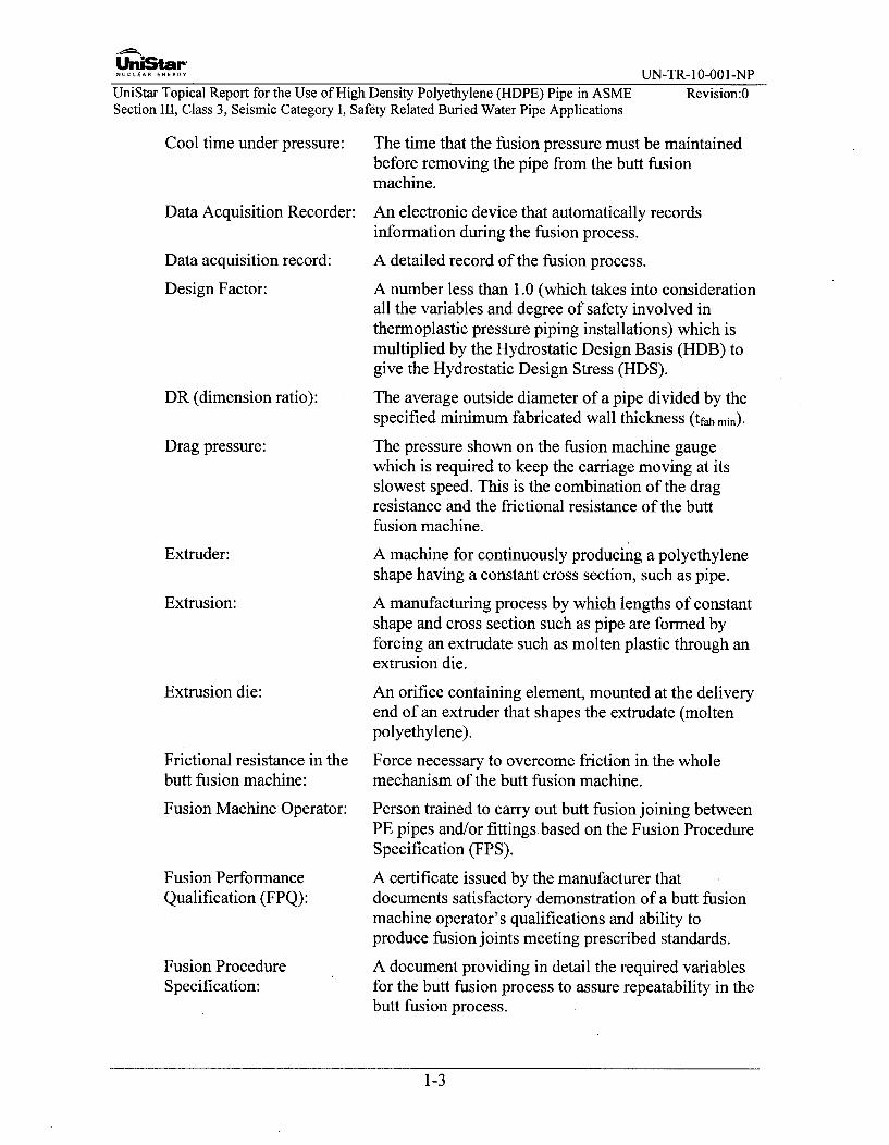
Cool time under pressure:
Data Acquisition Recorder:
Data acquisition record:
Design Factor:
DR (dimension ratio):
Drag pressure:
Extruder:
Extrusion:
Extrusion die:
The time that the fusion pressure must be maintainedbefore removing the pipe from the butt fusionmachine.
An electronic device that automatically recordsinformation during the fusion process.
A detailed record of the fusion process.
A number less than 1.0 (which takes into considerationall the variables and degree of safety involved inthermoplastic pressure piping installations) which ismultiplied by the Hydrostatic Design Basis (HDB) togive the Hydrostatic Design Stress (HDS).
The average outside diameter of a pipe divided by thespecified minimum fabricated wall thickness (tfab min).
The pressure shown on the fusion machine gaugewhich is required to keep the carriage moving at itsslowest speed. This is the combination of the dragresistance and the frictional resistance of the buttfusion machine.
A machine for continuously producing a polyethyleneshape having a constant cross section, such as pipe.
A manufacturing process by which lengths of constantshape and cross section such as pipe are formed byforcing an extrudate such as molten plastic through anextrusion die.
An orifice containing element, mounted at the deliveryend of an extruder that shapes the extrudate (moltenpolyethylene).
Force necessary to overcome friction in the wholemechanism of the butt fusion machine.
Person trained to carry out butt fusion joining betweenPE pipes and/or fittings based on the Fusion ProcedureSpecification (FPS).
A certificate issued by the manufacturer thatdocuments satisfactory demonstration of a butt fusionmachine operator's qualifications and ability toproduce fusion joints meeting prescribed standards.
A document providing in detail the required variablesfor the butt fusion process to assure repeatability in thebutt fusion process.
Frictional resistance in thebutt fusion machine:
Fusion Machine Operator:
Fusion PerformanceQualification (FPQ):
Fusion ProcedureSpecification:
1-3

UniStar"NUCLEAR...... UN-TR- 10-001-NP
UniStar Topical Report for the Use of High Density Polyethylene (HDPE) Pipe in ASME Revision:0Section III, Class 3, Seismic Category I, Safety Related Buried Water Pipe Applications
HDPE (High Density Polyethylene) Polyethylene with anASTM D3350 Density Cell Class of 3 or higher
Heater bead-up size:
Heater surface temperature:
Hydrostatic Design Basis:
Hydrostatic Design Stress:
IDR:
Interfacial pressure:
The size of a bead of PE formed between the pipe endand the heater surface during the butt fusion heatingcycle.
The temperature of the surface of the coated heaterplate.
One of a series of stress values for a PE compoundestablished in accordance with ASTM D2837 and PPITR-3 that is listed in PPI TR-4.
The estimated maximum tensile stress the material iscapable of withstanding continuously with a highdegree of certainty that failure of the pipe will notoccur. This stress is circumferential when internalhydrostatic water pressure is applied. HDS = HDB xDesign Factor.
The average inside diameter of a pipe divided by thespecified minimum fabricated wall thickness (tfab min).
The pressure selected for butt fusion from theinterfacial pressure range specified in the FPS.
A product constructed under a Certificate ofAuthorization or Accreditation, supports (NCA-3120),or material (NCA-1220).
Estimated tensile stress in the wall of the pipein the circumferential orientation that when appliedcontinuously will cause failure of the pipe at 100,000hours.
A naming convention for Polyethylene Compoundconsisting of the abbreviation for polyethylene, PE,followed by the ASTM D 3350 cell classificationvalue numbers for density and slow crack growthresistance, followed by the hydrostatic design stressrating for water at 73°F as defined by PPI TR-4.
The soil reaction modulus is a proportionality constantthat represents the embedment soil's resistance to ringdeflection of pipe due to earth pressure.
A Polyethylene Source Material for PolyethyleneCompound that does not contain black or colorpigmentation.
Item:
Long-termHydrostatic Strength:
Material Designation:
Modulus of soil reaction, E':
Natural Compound (NC):
1-4

UniStar-NUnC arEA ENERG UN-TR- 10-001-NP
UniStar Topical Report for the Use of High Density Polyethylene (HDPE) Pipe in ASME Revision:0Section III, Class 3, Seismic Category I, Safety Related Buried Water Pipe Applications
Natural CompoundManufacturer:
Part:
Polyethylene (PE):
PE Compound:
PE Source CompoundManufacturer:
PE Lot:
An organization that manufactures Natural Compoundin accordance with Section III of the ASME Code, butdoes not manufacture Pigment ConcentrateCompound.
An item which is attached to or becomes a portion of acomponent or support before completion and stampingof the component or support. Parts have workperformed on them requiring verification by anInspector.
A plastic obtained by polymerizing ethylene gas. It isnormally a translucent, tough, waxy solid which isunaffected by water and by a large range of chemicals.
Natural Compound combined with PigmentConcentrate Compound.
An organization that manufactures PE Compoundbut does not manufacture Pigment ConcentrateCompound.
The quantity shipped that is represented by theCertificate of Analysis or the Certified PE Test Report.The term "batch" rather than lot may appear on aCertificate of Analysis.
PE Compound manufactured into a product form,without joining.
An organization that uses either PE Compound orNatural Compound combined with PigmentConcentrate Compound to produce PE Material.
An organization that procures, receives, stores, andships PE Material, but does not perform or subcontractany design, examination, testing, marking, oroperations that affect the PE Material properties.
PE Material in the form of un-fused lengths of pipe.
Pipe, mitered elbows, and flanges.
An individual or organization that furnishesnondestructive examination, testing, or calibrationservices in accordance with a procurement document.
Products used for conversion to PE Material. NaturalCompound, Pigment Concentrate Compound, and PECompound are PE Source Materials. PE pipe is a
PE Material:
PE Material Manufacturer:
PE Material Supplier:
PE pipe:
PE product forms:
PE Service Supplier:
PE Source Material:
1-5

UniStar-NUCEARE UN-TR- 10-001-NP
UniStar Topical Report for the Use of High Density Polyethylene (HDPE) Pipe in ASME Revision:0Section III, Class 3, Seismic Category I, Safety Related Buried Water Pipe Applications
source material for other product forms such as pipesegments that are fused to form mitered elbows or pipesegments that are machined to form flange adapters.
PE Source MaterialManufacturer:
PENT
Percent Ovality:
Pigment ConcentrateCompound (PCC):
Pigment ConcentrateCompound Manufacturer:
Plastic extrusion (extrusion):
Resultant Moment:
Stiffness factor:
Supplier of SubcontractedServices:
Test coupon:
A manufacturer of PE Source Material such as aNatural Compound Manufacturer, PigmentConcentrate Compound Manufacturer, PE CompoundManufacturer, or PE Material Manufacturer.
Test method known as PENT (Pennsylvania NotchTest). ASTM F 1473 standard test method for notchtensile test to measure the resistance to slow crackgrowth of polyethylene pipes and resins.
The allowed difference between the maximummeasured diameter and the minimum measureddiameter divided by the measured average outsidediameter and multiplied by 100.
A compound made of PE with a high concentration ofcarbon black or colorant additives produced inaccordance with the Natural CompoundManufacturer's formulation requirements. (Thiscompound is often called "Master Batch")
An organization that manufactures PigmentConcentrate Compound in accordance with thisTopical Report and a procedure provided by theNatural Compound Manufacturer.
A process by which lengths of constant cross sectionmaterial (pipe) are formed by forcing moltenpolyethylene through a die.
The resultant moment is calculated per ND-3653.3 ofASME Section III. This includes all three momentcomponents combined using the square root sum ofsquares (SRSS) method.
The measurement of a pipe's ability to resist deflectionas determined in accordance with ASTM D2412.
An individual or organization that furnishesnondestructive testing, examination or calibrationservices in accordance with a procurement document.
A specimen prepared from a butt fusion joint that isused to qualify butt fusion procedures or operatorqualification.
1-6

UniSCAr UN-TR-10-001-NP
UniStar Topical Report for the Use of High Density Polyethylene (HDPE) Pipe in ASME Revision:0Section III, Class 3, Seismic Category I, Safety Related Buried Water Pipe Applications
Test specimen: A section of a butt fusion joint that is tested inaccordance with a testing procedure to qualify a buttfusion machine operator or fusion procedure.
1-7

UniStar"NUCLEAR ENERGY UN-TR- 10-001-NP
UniStar Topical Report for the Use of High Density Polyethylene (HDPE) Pipe in ASME Revision:0Section III, Class 3, Seismic Category I, Safety Related Buried Water Pipe Applications
2.0 CODES AND STANDARDS
2.1 ASME Boiler and Pressure Vessel Code
Design and analysis of ASME Class 3 piping for the U.S. EPRTM to be built byUniStar Nuclear Energy or its partners, is in accordance with the 2001 ASME Boilerand Pressure Vessel (B&PV) Code, Section III, Division 1, 2003 addenda. This isthe design code for the HDPE piping addressed in this Topical Report with therestriction that the treatment of dynamic loads, including seismic loads, in the pipestress analyses will be according to sub-articles ND-3650 of the 1993 Addenda ofthe ASME Code.
2.1.1 Section III, Division 1, Subsection ND
2.1.2 Section III, Division 1, Subsection NCA
2.1.3 Section V, Nondestructive Examination
2.1.4 Section XI, Rules for In-service Inspection of Nuclear Power Plants
2.1.5 B16.5-07, Pipe Flanges and Flanged Fittings: NPS 1/2 through 24
2.1.6 B 16.47-06, Large Diameter Steel Flanges: NPS 26 Through NPS 60 Standard
2.2 ASTM Polyethylene (PE) Material Standards
2.2.1 D422-63(re-approved 07), Standard Test Method for Particle - Size Analysis ofSoils
2.2.2 D638-08, Standard Test Method for Tensile Properties of Plastics
2.2.3 D698-07, Standard Test Methods for Laboratory Compaction Characteristics of SoilUsing Standard Effort (12,400 ft-lbf/ft3)
2.2.4 D746-07, Standard Test Method for Brittleness Temperature of Plastics andElastomers by Impact
2.2.5 D792-08, Standard Test Methods for Density and Specific Gravity (RelativeDensity) of Plastics by Displacement
2.2.6 D 1140-00, Standard Test Method for Amount of Materials in Soils Finer than No.200 Sieve
2.2.7 D1238-04c, Standard Test Method for Melt Flow Rates of Thermoplastics byExtrusion Plastometer
2.2.8 D 1505-03, Standard Test Method for Density of Plastics by the Density-GradientTechnique
2.2.9 D1556-07, Standard Test Method for Density of Soil in Place by the Sand-ConeMethod
2.2.10 D1557-09, Standard Test Methods for Laboratory Compaction Characteristics ofSoil Using Modified Effort (56,000 ft-lb f/fl)
2-1

UniStar-EAR E•• R• UN-TR- 10-001-NP
UniStar Topical Report for the Use of High Density Polyethylene (HDPE) Pipe in ASME Revision:0Section III, Class 3, Seismic Category I, Safety Related Buried Water Pipe Applications
2.2.11 D1598-02(re-approved 09), Standard Test Method for Time-to-Failure of Plastic
Pipe under Constant Internal Pressure
2.2.12 D 1603-06, Standard Test Method for Carbon Black Content in Olefin Plastics
2.2.13 D2216-05, Standard Method of Laboratory Determination of Moisture Content ofSoil
2.2.14 D2290-08, Standard Test Method for Apparent Hoop Tensile Strength of Plastic orReinforced Plastic Pipe by Split Disk Method
2.2.15 D2412-02(re-approved 08), Standard Test Method for Determination of ExternalLoading Characteristics of Plastic Pipe by Parallel-Plate Loading
2.2.16 D2487-06, Classification of Soils for Engineering Purposes
2.2.17 D2774-08, Standard Practice for Underground Installation of Thermoplastic PressurePiping
2.2.18 D2837-08, Standard Test Method for Obtaining Hydrostatic Design Basis forThermoplastic Pipe Materials or Pressure Design Basis for Thermoplastic PipeProducts
2.2.19 D3035-08, Standard Specification for PE Plastic Pipe (DR-PR) Based on ControlledOutside Diameter
2.2.20 D3261-1Oa, Standard Specification for Butt Heat Fusion Polyethylene (PE) PlasticFittings for PE Plastic Pipe and Tubing
(D3261-10a is for molded fittings, and shall be used only for molded flangeadapters)
2.2.21 D3350-10, Standard Specification for PE Plastics Pipe and Fittings PE compounds
2.2.22 D4218-96(re-approved 08), Standard Test Method for Determination of CarbonBlack Content in PE Compounds by the Muffle-Furnace Technique
2.2.23 D4253-00(re-approved 06), Standard Test Methods for Maximum Index Density andUnit Weight of Soils Using a Vibratory Table
2.2.24 D4318-05, Test Methods for Liquid Limit, Plastic Limit & Plasticity Index of Soils
2.2.25 D4883-08, Standard Test Method for Density of Polyethylene by the UltrasoundTechnique
2.2.26 F412-09, Standard Terminology Relating to Plastic Piping Systems
2.2.27 F714-08, Standard Specification for PE Plastic Pipe (SDR-PR) Based on OutsideDiameter
2.2.28 F 1473-07, Standard Test Method for Notch Tensile Test to Measure the Resistanceto Slow Crack Growth of PE Pipes and Resins
2.2.29 F 1668-08, Standard Guide for Construction Procedures for Buried Plastic Pipe
2-2
UniStar-NUCLEA.ENERGY UN-TR- 10-001-NP
UniStar Topical Report for the Use of High Density Polyethylene (HDPE) Pipe in ASME Revision:0Section III, Class 3, Seismic Category I, Safety Related Buried Water Pipe Applications
2.2.30 F2164-02(re-approved 07), Standard Practice for Field Leak Testing of Polyethylene(PE) Pressure Piping Systems Using Hydrostatic Pressure
2.2.31 F2206-02, Standard Specification for Fabricated Fittings of Butt-Fused PE PlasticPipe, Fittings, Sheet Stock, Plate Stock, or Block Stock
2.2.32 ASTM F2263-09 Standard Test Method for Evaluating the Oxidative Resistance ofPE Pipe to Chlorinated Water
2.2.33 F2620-0961 Standard Practice for Heat Fusion Joining of PE Pipe and Fittings,(Superscript " is for minor March 2010 editorial Change)
2.2.34 F2634-07 Standard Test Method for Laboratory Testing of Polyethylene (PE) ButtFusion Joints using Tensile-Impact Method
2.2.35 F2769-09, Standard Specification for PE of Raised Temperature (PE-RT) Plastic Hotand Cold-Water Tubing and Distribution Systems
2.3 Plastic Pipe Institute (PPI)
2.3.1 PPI TR-3-2008, Policies and Procedures for Developing Hydrostatic Design Basis(HDB), Pressure Design Basis (PDB), Strength Design Basis (SDB) and MinimumRequired Strength (MRS) Ratings for Thermoplastic Piping Materials or Pipe
2.3.2 PPI TR-4-2009, PPI Listing of Hydrostatic Design Basis (HDB), Hydrostatic DesignStress (HDS), Strength Design Basis (SDB), Pressure Design Basis (PDB) andMinimum Required Strength (MRS) Ratings for Thermoplastic Piping Materials orPipe
2.3.3 PPI Technical Report TR-33-2006, Generic Butt Fusion Joining Procedure for FieldJoining of PE Pipe
2.3.4 PPI TN-16-2008 Rate Process Method for Projecting Performance of PE PipingComponents
2.3.5 PPI TN-38-2007 Bolt Torque for PE Flanged Joints
2.3.6 PPI TN-42-2009 Recommended Minimum Training Guidelines for PE Pipe ButtFusion Joining Operators for Municipal and Industrial Projects
2.4 International Standards Organization (ISO)
2.4.1 ISO TR 19480-2005, Thermoplastics pipes and fittings for the supply of gaseousfuels or water - Guidance for training and assessment of fusion operators
2-3

UniStarPNUCLEAR ENERGY UN-TR-10-001-NP
UniStar Topical Report for the Use of High Density Polyethylene (HDPE) Pipe in ASME Revision:0Section III, Class 3, Seismic Category I, Safety Related Buried Water Pipe Applications
3.0 PIPING STRESS ANALYSIS CRITERIA
3.1 Piping Seismic Classifications
This Topical Report pertains to buried piping classified as Seismic Category I, whichin accordance with Regulatory Guide (RG) 1.29, "Seismic Design Classification," isrequired to be designed to withstand the effects of a Safe Shutdown Earthquake(SSE) and remain functional during and after the event.
3.2 Service Levels
The U.S. EPRTM to be built by UniStar Nuclear Energy or its partners utilizes thefour Service Levels used in the ASME Code, Levels A, B, C and D, and testingconditions, in the design of piping. These four service level designations also havethe alternate naming convention of Normal, Upset, Emergency and Faulted,respectively. Load cases have been developed for the four defined Service Levelsbased on the guidance in Standard Review Plan (SRP) 3.9.3. The general definitionsof each of the four levels are as follows:
A. Level A (Normal)
Level A refers to sustained loadings encountered during normal plant/systemstart-up, operation, refueling and shutdown.
B. Level B (Upset)
Level B refers to occasional, infrequent loadings deviating from normal plantconditions, but having a high probability of occurrence. Piping and pipesupports will be designed to withstand these loading conditions withoutsustaining any damage or reduction in function.
C. Level C (Emergency)
Level C refers to infrequent loadings with a low probability of occurrence, whichis considered as design basis loadings causing no significant loss of integrity.Such an occurrence requires the unit to be shut down for inspection and repair toany damaged components prior to re-start.
D. Level D (Faulted)
Level D refers to infrequent loadings with an extremely low probability ofoccurrence, associated with design basis accidents (such as Safe ShutdownEarthquake, Design Basis Pipe Break and Loss of Coolant Accident). PerRegulatory Guide 1.29, safety related SSCs must retain their ability whererequired to ensure:
3-1

UniStar-NUCLEAR.E.ERY UN-TR-10-001-NP
UniStar Topical Report for the Use of High Density Polyethylene (HDPE) Pipe in ASME Revision:0Section III, Class 3, Seismic Category I, Safety Related Buried Water Pipe Applications
1) The integrity of the reactor coolant pressure boundary,
2) The capability to shut down the reactor and maintain it in a safe shutdowncondition,
3) The capability to prevent or mitigate the consequences of accidents that couldresult in potential offsite exposures comparable to the guideline exposures of10 CFR Part 50.34(a)(1) or 10 CFR Part 100.11.
E. Testing
Pressure tests such as hydro tests are included in the piping analysis for primarymembrane stresses.
3.3 Load Cases and Load Combinations
3.3.1 Loadings
A. Pressure
Internal design pressure, PD, is used in the design and analysis of ASME CodeClass 3 piping. Minimum pipe wall thickness calculations are performedutilizing design pressure. Design pressures and maximum service pressures areused in load combinations for calculating stresses for Design Conditions, ServiceLevels A, B, C and D and Testing.
B. Deadweight
Deadweight loads are calculated by applying a negative vertical acceleration tothe pipe, contents, and in-line components (for unburied portion). Trench loadsand water weight are also considered in the stress analysis.
C. Transportation Loading
The effects of vehicles (vehicles and railroads) driving over the buried piping areconsidered in the design and analysis.
D. Thermal Expansion
The effects on piping thermal expansion and contraction are considered in thedesign. Various operating modes are considered in order to determine the mostsevere thermal loading conditions. The zero thermal load temperature is taken as70 0F.
E. Seismic
The effects of seismic inertial loads and anchor movements are included in thedesign analysis. The design of the U.S. EPRTM Seismic Category I pipingincludes analysis of the inertial movements and building anchor movement(>1/16") as a result of a Safe Shutdown Earthquake (SSE). These loads areService Level D loads.
F. Building Settlement Loadings
Loads due to the displacements of a building anchor or support over time areconsidered in the design and analysis.
3-2

UniStarNUCLEAR ENERGY UN-TR- 10-001-NPUniStar Topical Report for the Use of High Density Polyethylene (HDPE) Pipe in ASME Revision:0Section III, Class 3, Seismic Category I, Safety Related Buried Water Pipe Applications
G. Fluid Transient Pressure Surge Loadings
The effects of water hammer pressure surge loads are considered in the designand analysis of HDPE pipe and are limited as described in Section 3.10.4.
H. Hydro tests
Piping systems are tested for leaks by filling the system with the test fluid to testpressures.
3.3.2 Load Combinations
Using the methodology and equations from the ASME Code, pipe stresses arecalculated for various load combinations. The ASME Code includes design limitsfor Design Conditions, Service Levels A, B, C and D and testing. Loadcombinations for Class 3 piping are illustrated in Table 3-2.
3.3.3 Design and Service Loading
Design loads are as defined in ASME Section III, ND-3112.1 through ASMESection III, ND-3112.3. Loads applied to buried PE piping system are specified inthe Design Specification. Design Specification content shall include, but not belimited to, the following:
(a) Internal design pressure PD, for pressure design in accordance with Sections 3.10and 3.10.6.
(b) Maximum and minimum temperature, T, for the selection of allowable stress(Section 3.10, Section 3.12.1 and Section 9.4) and design for temperature effectsin accordance with Section 3.12.1. The maximum Service Level A temperatureis the Design Temperature, TD.
(c) Maximum flow velocity, v, and the stress limits for the pressure spike loadsresulting from the maximum flow velocity, v.
(d) Vertical soil pressure due to earth loads, PE, vertical pressure due to surchargeloads, PL, pressure due to ground water, Pgw, including pressure resulting fromsaturated soil weight, surcharge, buoyancy and flotation, for design inaccordance with Section 3.14.
(e) Permanent ground movement, soil settlement, for design as non-repeated anchormovements in accordance with Section 3.13 and 3.14.
(f) Seismic wave passage and seismic soil movement and building anchor motionsfor seismic design in accordance with Section 3.15.
(g) Ground movement caused by frost heave for design of expansion and contractionin accordance with Section 3.12.2.
(h) The duration of load for each load case. The PE pipe physical and mechanicalproperties are based on the duration of load.
(i) Consideration for the cumulative effect from loads of different duration.
3-3

UniStar-UN-TR- 10-001-NP
UniStar Topical Report for the Use of High Density Polyethylene (HDPE) Pipe in ASMESection III, Class 3, Seismic Category I, Safety Related Buried Water Pipe Applications
Revision:0
Table 3-1: Design Conditions and Stress Criteria for Class 3 Piping
Service Level Stress Condition Capacity Criteria
Minimum Wall Thickness Requirements of Section 3.10Design Primary - Longitudinal Stress Requirements of 3.11.1 with k = 1.0
Primary - Sidewall Compression Scomp, Table 3-12 (Section 3.14.2)
Primary - Buckling due to External Pressure Requirements of Section 3.14.3.A
Primary - Flotation Requirements of Section 3.14.4
A Primary - Pressure Less than 1.0 x PD
Primary - Longitudinal Stress Requirements of 3.11.1 with k = 1.0
Secondary - Thermal 11 00psi (Section 3.12.2.C)
Non Repeated Anchor Motion 2 x S (Section 3.13)
Primary - Sidewall Compression Scomp, Table 3-12 (Section 3.14.2)
Primary - Buckling due to External Pressure Requirements of Section 3.14.3.APrimary - Flotation Requirements of Section 3.14.4
B Primary - Pressure Less than 1.1 X PDPrimary - Surge Pressure 1.5 x PD
Primary - Longitudinal Stress Requirements of Section 3.11.1 or0.4xMaterial Tensile strength at Yield
Secondary - Thermal 11 00psi (Section 3.12.2.C)
Primary - Sidewall Compression Scamp, Table 3-12 (Section 3.14.2)
Primary - Buckling due to External Pressure Requirements of Section 3.14.3.A
Primary - Flotation Requirements of Section 3.14.4CPrimary - Pressure Less than 1.33 x PD
Primary - Surge Pressure 1.5 x PD
Secondary - Thermal 11 00psi (Section 3.12.2.C)
Primary - Sidewall Compression Scomp, Table 3-12 (Section 3.14.2)
Primary - Buckling due to External Pressure Requirements of Section 3.14.3.A
Primary - Flotation Requirements of Section 3.14.4
D Primary - Pressure Less than 1.33 x PD
Primary - Surge Pressure 1.5 X PD
Secondary - Thermal 11 00psi (Section 3.12.2.C)
Secondary - Seismic 11 00psi (Section 3.15)
Note: Terms are defined in Section 3.7
3-4

UniStar-NUCLEAR ENERGY UN-TR-10-001-NPUniStar Topical Report for the Use of High Density Polyethylene (HDPE) Pipe in ASMESection III, Class 3, Seismic Category I, Safety Related Buried Water Pipe Applications
Revision:0
Table 3-2: Load Combinations
Service Level Stress Condition Load Combination
_______________________PD+DWDesign PD
Primary - Sidewall Compression PE + PL
Primary - Buckling due to External Pressure PE + PL +Pgw
Primary - Flotation w
A Primary - Pressure Pa
Primary - Longitudinal Stress Pa+DW
Secondary - Thermal Range (Ta min, Ta max)
Non Repeated Anchor Motion BS
Primary - Sidewall Compression PE + PL
Primary - Buckling due to External Pressure PE + PL +Pgw
Primary - Flotation w
B Primary - Pressure Pb
Primary - Pressure + Surge Pressure Pb+Pbs
Primary - Longitudinal Stress Pb + DW
Secondary - Thermal Range (Tb min, Tb max)
Primary - Sidewall Compression PE + PL
Primary - Buckling due to External Pressure PE + PL +Pgw
C Primary - Flotation w
Primary - Pressure
Primary - Surge Pressure P+
Secondary - Thermal Range (Tc min, Tcmax)
Primary - Sidewall Compression PE + PL
Primary - Buckling due to External Pressure PE + PL +Pgw
Primary - Flotation w
D Primary- Pressure Pd
Primary - Surge Pressure Pd+Pds
Secondary - Thermal Range (Td min, Td max)
Secondary - Seismic [SSEW2 + (SSEs+SSED) 2]1/2
Note: Terms are defined in Section 3.7
3-5

UniStarNUCLEA.ENERGY UN-TR-10-001-NP
UniStar Topical Report for the Use of High Density Polyethylene (HDPE) Pipe in ASME Revision:0Section III, Class 3, Seismic Category I, Safety Related Buried Water Pipe Applications
3.4 Fatigue Evaluation
3.4.1 Code Class 3 Piping
Class 3 HDPE piping is evaluated for fatigue due to thermal cycles by following thegeneral requirements in ND-3611.2 of the ASME Code. When applicable, thisinvolves the reduction of HDPE allowable stresses based on the number of full rangetemperature cycles over the plant design life. EPRI Report 1015062 recommendsthe use of a "Stress Range Reduction Factor" only when the number of full rangetemperature cycles over the plant design life exceeds 7000 cycles. As noted inSection 9.5 (and in EPRI Report 1015062), normal operation of buried HDPE pipingin Class 3 essential service water piping systems is essentially a steady statecondition with little or no..temperature variation, therefore fatigue due to temperaturecycles will be negligible.
In addition, the stress intensification factors (SIFs) and stress indices (B1 and B 2)used in equations for calculating stresses at components are based on fatigue testingof HDPE piping, and are provided in Sections 3.11, 3.12, and 4.6, and thereforeindirectly account for fatigue in Class 3 HDPE piping components. No cumulativeusage factor is calculated for HDPE Class 3 piping. See Section 9.5 for details onfatigue loading.
3.5 Functional Capability
General Design Criterion 2 of 10 CFR Part 50 requires that Class 3 piping systemsessential for safe shutdown of the plant remain capable of performing their safetyfunction for Service Level D loading conditions. This criterion is met by meetingthe recommendations in NUREG-1367, "Functional Capability of Piping Systems."Table 3-3 summarizes the criteria to be used to ensure that the functional capabilityrequirement of GDC 2 is met.
3-6

UniStar"......... UN-TR- 10-001-NP
UniStar Topical Report for the Use of High Density Polyethylene (HDPE) Pipe in ASME Revision:0Section III, Class 3, Seismic Category I, Safety Related Buried Water Pipe Applications
Table 3-3: Functional Capability of Piping ASME Class 3
Criteria Class 3
Equation Allowable
Wall Thickness Ddt < 50 Meet
Service Level D Primary - Requirements of Section 3.11.1 or 0.4 x MaterialLongitudinal Stress Tensile strength at Yield
External Pressure Pextemai _< Pinternai Meet
Notes:1. General Note: Applicable to Level D plant events for which the piping system must maintain an
adequate fluid flow path.2. General Note: Applicable to ASME Code Class 3 when the following are met:
a. Dynamic loads are reversing
b. Steady-state bending stress from deadweight loads does not exceed: B2M < 0.25SZ
3.6 Material Properties
Piping materials are made from a bimodal pipe grade high density polyethylenematerial and conform to the requirements specified in Appendix B. Materials willhave an ASTM D3350 cell classification of 445574C. Pipe will be manufactured inaccordance with Appendix B and ASTM D3035 for sizes below 3" NPS, and ASTMF714 for sizes 3" NPS and larger.
3.6.1 Material Designation
The HDPE pipe material designation code identifies the standard classification ofessential properties. For this Topical Report one designation is used, PE 4710.
* The first two letters, "PE" designates that the material is a polyethylenepiping material.
* The first digit, 4, identifies the resin's density classification in accordancewith ASTM D3350. Certain properties, including stress/strain response aredependent on the crystalline content.
* The second digit, 7, identifies the material's standard classification for slowcrack growth resistance, also in accordance with ASTM D3350, whichrelates to the resin's capacity for resisting the initiation and propagation ofslowly growing cracks when subjected to localized stress intensification. ForPE 4710, the 7 denotes a minimum PENT rating of 500hrs; however, thisTopical Report requires a higher PENT rating of at least 2000hrs.
* The third and fourth digit combined, 10, denotes the material's recommendedhydrostatic design stress (HDS), for water at 73°F, in units of 100psi. For PE4710, the 10 represents a HDS of 1 000psi, however this Topical Reportrequires a more conservative (lower) HDS of 800psi.
3-7

UiniStar'N.U.CLEA FNRGY UN-TR- 10-001-NP
UniStar Topical Report for the Use of High Density Polyethylene (HDPE) Pipe in ASME Revision:0Section III, Class 3, Seismic Category I, Safety Related Buried Water Pipe Applications
3.6.2 Stress/Strain represented by an Apparent Modulus
The potential range of stress/strain response of a material is bounded by twoextremes. At one extreme the response can be perfectly elastic, where the magnitudeof the strain is always proportional to the magnitude of the applied stress. At theother extreme, deformation caused by the application of a stress is neitherinstantaneous nor proportional to the stress. Deformation is delayed and the rate andthe final extent of deformation are dependant upon the magnitude and duration of theapplied stress. Apparent modulus can also be derived for the condition ofcompressive stress. Such a value tends to be somewhat larger because the resultantdeformation causes a slight increase in the area that resists the applied stress;however, the resultant increase is generally small allowing the tensile stress value toadequately and conservatively represent the compression state.
Even though PE piping materials exhibit visco-elastic behavior, this concept allowsfor piping design to be conducted by means of the same equations that have beendeveloped based on the assumption of elastic behavior; however, it is important torecognize that a value of an apparent modulus that is used for a design mustadequately reflect the visco-elastic response that is expected to occur under theanticipated service conditions. In this regard, it should be noted that a value ofapparent modulus is dependent not only on duration of loading, but also on stressintensity. In nearly all PE pipe applications the maximum stresses that are generatedby reactions other than that which is caused by internal pressure are of a magnitudethat seldom exceeds the range of about 300 to 400psi (Reference 13.1.7).
3.6.3 Determination of Working Strength
The working tensile strength of PE is affected by essentially the same variables thataffect its stress/strain relationship; principally, magnitude of load, duration ofloading, temperature and environment. One important difference is that unlike strainresponse which is in reaction to the nominal value of applied stress, fracture canresult from either the effect of a nominal stress, or from that of a local intensifiedstress.
In a pressure pipe application, the major nominal stress is that which is induced byinternal hydrostatic pressure. Accordingly, standards for pressure rated PE piperequire that each material from which a PE pipe is made have an experimentallyestablished long-term hydrostatic strength (LTHS). The pressure rating of a PE pipeis based on this hydrostatic design basis after it has been reduced to a hydrostaticdesign stress (HDS) by means of applying a design factor (DF) that gives adequateconsideration to the additional nominal and localized stresses that can be generatedby other conditions.
3.6.4 Compressive Strength
Unlike tensile loading, which can result in a failure if excessive, a compressiveloading seldom leads to a fracture. Instead, there is a resultant creep in compression,which causes a thickening of the areas resisting the stress; an effect that tends toreduce the true stress. If the stress is excessive, failure can occur by yielding(excessive deformation) rather than by a fracture process. For these reasons, it is
3-8

UniStarNUCLEAR.E.ERY UN-TR- 10-001-NP
UniStar Topical Report for the Use of High Density Polyethylene (HDPE) Pipe in ASME Revision:0Section 1II, Class 3, Seismic Category I, Safety Related Buried Water Pipe Applications
customary to report compressive strength as the stress required to deform a testsample to a certain strain.
3.6.5 Other Engineering Properties
A. Mechanical Properties
Poisson's Ratio - Any stretching or compressing of a test specimen in onedirection, due to uniaxial force (below the yield point) produces an adjustment inthe dimensions perpendicular to the force. A tensile force in the axial directioncauses a small contraction in the lateral direction. The ratio of the decrease inlateral strain to the increase in axial strain is called Poisson's ratio (v).
Impact Strength - The concept of impact strength covers at least two importantproperties:
1) The magnitude of a suddenly applied energy that causes the initiation andpropagation of a crack. This is usually assessed by the results of tests on un-notched or bluntly notched specimens.
2) The magnitude of a suddenly applied energy that causes a crack to rapidlypropagate. This is usually assessed by means of very sharply notchedspecimens.
B. Thermal Properties
Coefficient of Expansion/Contraction - A temperature increase or decrease caninduce a corresponding increase or decrease in the length of a pipe, themovement of which is unconstrained. In the case of a constrained pipe, it caninduce the development of a longitudinal tensile or a compressive stress. Boththese effects must be given adequate consideration for the proper installation,design, and operation of a PE piping system.
Thermal Conductivity - The capacity of PEmaterials to conduct heat is onlyabout one hundredth of that of steel or copper.
Specific Heat - Over the range of typical working temperatures, the quantity ofheat required to produce a unit temperature rise per unit mass of PE pipe materialis about 46% of that for water; this capacity is little affected by resin density.
3.6.6 Material Classification Properties
Density - The crystalline content of a PE resin is reflected by its density. As noted inSection 3.6.1, the crystalline content exerts a major influence on the properties of aPE resin. Generally, as crystalline content increases so does stiffness (apparentmodulus), tensile strength, and softening temperature, however, for a given kind ofmolecular structure, there is a corresponding decrease in impact strength and in lowtemperature toughness.
Melt Index - The melt index is a measure of the flowability of PE materials when inthe molten state. This property is an accepted index for two important characteristicsof a PE piping material: 1) its processability, and 2) the molecular weight of itsprimary constituent PE resin.
3-9
UniStar-NUCLEA.ENERGY UN-TR- 10-001 -NP
UniStar Topical Report for the Use of High Density Polyethylene (HDPE) Pipe in ASME Revision:0Section III, Class 3, Seismic Category I, Safety Related Buried Water Pipe Applications
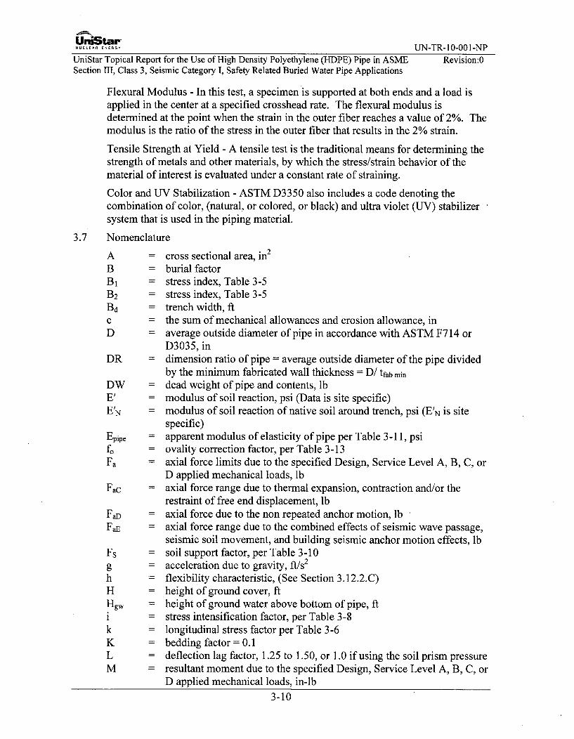
Flexural Modulus - In this test, a specimen is supported at both ends and a load isapplied in the center at a specified crosshead rate. The flexural modulus isdetermined at the point when the strain in the outer fiber reaches a value of 2%. Themodulus is the ratio of the stress in the outer fiber that results in the 2% strain.
Tensile Strength at Yield - A tensile test is the traditional means for determining thestrength of metals and other materials, by which the stress/strain behavior of thematerial of interest is evaluated under a constant rate of straining.
Color and UV Stabilization - ASTM D3350 also includes a code denoting thecombination of color, (natural, or colored, or black) and ultra violet (UV) stabilizersystem that is used in the piping material.
3.7 Nomenclature
A = cross sectional area, in2
B = burial factorB1 = stress index, Table 3-5B2 = stress index, Table 3-5Bd = trench width, ftc = the sum of mechanical allowances and erosion allowance, inD = average outside diameter of pipe in accordance with ASTM F714 or
D3035, inDR = dimension ratio of pipe = average outside diameter of the pipe divided
by the minimum fabricated wall thickness = D/ tfab min
DW = dead weight of pipe and contents, lbE' = modulus of soil reaction, psi (Data is site specific)E'N = modulus of soil reaction of native soil around trench, psi (E'N is site
specific)Epipe = apparent modulus of elasticity of pipe per Table 3-11, psifo = ovality correction factor, per Table 3-13Fa = axial force limits due to the specified Design, Service Level A, B, C, or
D applied mechanical loads, lbFac = axial force range due to thermal expansion, contraction and/or the
restraint of free end displacement, lbFaD = axial force due to the non repeated anchor motion, lbFaE = axial force range due to the combined effects of seismic wave passage,
seismic soil movement, and building seismic anchor motion effects, lbFs = soil support factor, per Table 3-10g = acceleration due to gravity, ft/s2
h = flexibility characteristic, (See Section 3.12.2.C)H = height of ground cover, ftHgw = height of ground water above bottom of pipe, fti = stress intensification factor, per Table 3-8k = longitudinal stress factor per Table 3-6K = bedding factor = 0.1L = deflection lag factor, 1.25 to 1.50, or 1.0 if using the soil prism pressureM = resultant moment due to the specified Design, Service Level A, B, C, or
D applied mechanical loads, in-lb3-10

Uni~tar"NU CLEAR.EN ERG U N -T R -10-00 1-N P
UniStar Topical Report for the Use of High Density Polyethylene (HDPE) Pipe in ASME Revision:0Section III, Class 3, Seismic Category I, Safety Related Buried Water Pipe Applications
Mc
MD
ME
Melb
MDFP
AP
Pn
PnsPD
PEPgwPhydro
PLPm
RR1
r2
S
SDR
Scomp
SSEwSSEsSSEDTATATeq
= resultant moment range due to thermal expansion, contraction and/orthe restraint of free end displacement, in-lb
= resultant moment due to the non repeated anchor motion, in-lb= resultant moment range due to the combined effects of seismic wave
passage, seismic soil movement, and building seismic anchor motioneffects, in-lb
= the inter curve length of the last heavy wall segment of the miteredelbow that contains the taper shown in Figure 7-2
= the total length of pipe to be able to get two clamps on the elbow in thefusing machine to securely hold the mitered elbow while fusing it tostraight pipe. This length includes the miter safe end and the last mitersegment that contains the counter-bore.
= Manufacturer de-rating factors for HDPE fittings= internal piping pressure, including pressure spikes due to transients
from anticipated water hammer events, psi= differential pressure due to negative internal pressure of pipe and
miters, psi= design or Service Level A, B, C, or D internal pressure, psi specified in
the Design Specification= Surge pressures for Service Levels B through D, psi= internal design pressure at the specified design temperature TD, both
specified in the Design Specification, not including consideration ofpressure spikes due to transients, psi
= vertical soil pressure due to earth loads, lb/ft2= pressure due to ground water, lb/ft2
= external hydrostatic pressure, equal to earth plus groundwater pressureplus surcharge load, psi
= vertical soil pressure due to surcharge loads, lb/ft2
= Miter elbow internal design pressure at TD; includes 50% repetitivesurge overpressure tolerance, psi
= buoyancy reduction factor= effective radius of miter bend, defined as the shortest distance from the
pipe centerline to the intersection of the planes of adjacent miter joints.= elbow mean radius of pipe using nominal wall telb
= allowable stress, also referred to as HDS, (HDS=HDBxDF), (Table3-4)
= (Standard Dimension Ratio) a specific ratio of the average specifiedoutside diameter to the minimum specified wall thickness (Dot) foroutside diameter controlled plastic pipe.
= allowable side wall compression stress per Table 3-12= Safe Shutdown Earthquake due to effects of seismic wave passage= Safe Shutdown Earthquake due to effects of soil movement= Safe Shutdown Earthquake due to effects of anchor movements= Temperature, OF= Twater - Tground, OF= equivalent temperature rise, OF
3-11

UniStar -N.............Y UN-TR- 10-001-NP
UniStar Topical Report for the Use of High Density Polyethylene (HDPE) Pipe in ASME Revision:0Section III, Class 3, Seismic Category I, Safety Related Buried Water Pipe Applications
TD = Design Temperature, OFt = nominal pipe wall thickness, in = tfab mintdesign = minimum required wall thickness, intfab min = minimum fabricated thickness in accordance with ASTM F714 or
ASTM D3035, intflange = Flange adapter wall thickness, intmin = minimum wall thickness for pressure, intelb = minimum elbow miter pipe wall-thickness (per Design Specification)Tground = temperature of soil around pipe, OFTn max = maximum temperature for Service levels A though D, OFTn min = minimum temperature for Service levels A though D, °FTwater = temperature of water running through pipe, OF
v = maximum flow velocity of water in pipe, ft/sWc = weight of pipe contents (equals 0 when pipe is empty), lb/ftWp = weight of pipe per unit length, lb/ft (exclude weight of contained liquid
to represent the worst case of an empty pipe)W, = weight of water displaced by pipe, per unit length, lb/ftZ = section modulus of pipe, in3
a = coefficient of thermal expansion of pipe, 1/0F0 = elbow angle of miter cut of pipe end (degrees)telb = elbow angle of change-in-direction at miter joint = 20
v = Poisson ratio (0.35 for short duration loads (5 min. or less) to 0.45 forlong duration loads (greater than 5 min.))
92 = (ring deflection) change in diameter as a percentage of the originaldiameter, commonly called the change in ring diameter, calculated inTable 3-9
92max = (maximum allowable ring deflection) maximum allowable change indiameter as a percentage of the original diameter, commonly called themaximum change in ring diameter, Table 3-9
Ca = Strain in the pipe from earthquake wave computer analysis (in/in)6b = Bending strain in the buried piping due to wave propagationFsoil = maximum soil strain due to seismic wave passage (in/in)Pdry = density of dry soil, lb/ft3 specified in the Design SpecificationPsaturated = density of saturated soil, lb/ft3
GE = tensile stress in the pipe due to an earthquake, psiosw = circumferential compressive stress in the sidewalls of the pipe and
miters, psiUt = tensile stress in the pipe, psi
3-12

UriiStar-.UC..L.. EN.G UN-TR-10-001-NP
UniStar Topical Report for the Use of High Density Polyethylene (HDPE) Pipe in ASME Revision:0Section 1II, Class 3, Seismic Category I, Safety Related Buried Water Pipe Applications
3.8 Hydrostatic Design Basis for Temperatures Over 140'F and Up To 160'F
The Plastic Pipe Institute studied the methods for forecasting the effective long termperformance of polyethylene piping materials. As a result of the study, theHydrostatic Stress Board has determined that the three-coefficient Rate ProcessMethod (RPM) equation provides the best correlation between the calculated long-term performance projections and known field performance of several PE pipingmaterials. The RPM is described in ASTM D2837 and Plastic Pipe InstituteTechnical Note TN- 16.
See Section 9.4 for a detailed discussion on elevated temperature design.
3.9 Slow Crack Growth Resistance
The average failure time from two test specimens shall meet the minimumrequirement shown for each cell classification listed in Table 1- "Primary Properties- Cell Classification Limit" from ASTM D 3350. The cell classification for PE 4710is PE445574C (this classification exceeds the minimum PE 4710 tensile strengthrequirement) which requires a minimum PENT test of 500hrs. The PE 4710 materialused for safety related systems shall exceed this minimum ASTM value, and shallhave a minimum ASTM F1473 PENT test rating of at least 2000hrs (See AppendixB for detailed PE 4710 piping material requirements).
Given the conservative limitations on pipe flaw size specified in Section 10.4.1, thishigh PE 4710 PENT value ensures Slow Crack Growth brittle failure will not occurduring the design life. Section 10.4.1 limits the maximum flaw size to notch depthof 0.125", while a PENT test on a pipe wall thickness of 4.5" is based on a muchlarger flaw and uses a notch depth of 0.347" (for a 0.787" pipe wall the PENT testwould use a notch depth of 0.205".)
The April 2007 Issue 4 of the Journal of Polymer Engineering and Science, pp 477-480, provides an equation for the correlation between PENT and HDPE pipingservice life. This equation shows that for a given stress intensity (pipe flaw) pipingservice life is directly proportional to the PENT value. As noted in JanaLaboratories Technical Report "Long-Term Performance of PE Piping Materials inPotable Water Applications," dated 9/17/2009, and listed in the PPI listing of"Municipal / Industrial Publications," accelerated laboratory testing per ASTMF2263 found that PE3408 pipe will have a potable water design life well beyond 100years. This finding was for an older unimodal HDPE resin that had a minimumPENT value of 100 hours.
The minimum PENT value of 2000 hours noted above is 20 times larger, and basedon the above correlation between design life and PENT would indicate a 20 timeslonger design life of 2000 years.
3.10 Pressure Design of Pipe
As explained in Section 9.1, Table 3-4 allowable stresses, S, are based on a DF of0.5. The design for temperatures above 140'F is described in Section 9.4.
3.10.1 Minimum Required Wall Thickness
3-13

Un•Star'NUCLEAR ENERGY UN-TR- 10-001-NP
UniStar Topical Report for the Use of High Density Polyethylene (HDPE) Pipe in ASME Revision:0Section III, Class 3, Seismic Category I, Safety Related Buried Water Pipe Applications
The internal pressure design thickness of straight sections of pipe is determined bythe following equation:
tdesign tmin + C
PDotmin -- D2S +PD•
3.10.2 Maximum Required Dimension Ratio
The following maximum required dimension ratio equations are equivalent to, (andare derived from) the minimum wall thickness equation above; and provide a moredirect and efficient method for sizing HDPE pipe to roughly match the ID of a steelpipe.
These equations are derived from the Minimum Wall Thickness equation by dividingboth sides of the equation by "t", substituting DR for the resultant D/t term, and thenrearranging terms to solve for DR. The IDR equation is derived by substituting (Di +2t) for D before dividing both sides of the equation by "t."
The internal pressure maximum required dimension ratio of straight sections of pipeis determined by the following:
D,DR =
t
D,IDR D=
t
DR = IDR + 2, (D, = Di + 2t)DR =2S±
DRmax = + IPD
IDRmax 2SPD
The dimension ratio is an equivalent indirect representation of the pipe wallthickness, and is used with HDPE, since HDPE pipe has standard pipe wallsspecified by dimension ratios (DR or IDR).
When HDPE pipe interfaces with steel pipe, the HDPE pipe will have a much thickerpipe wall for the same design conditions, therefore, the interfacing HDPE pipe willbe sized to roughly match the ID of the steel pipe, and the above IDRmx equationwill be used to select a pipe wall thickness.
The IDRmax will be used to select a pipe wall with a Standard IDR that is equal to orless than the calculated IDRmax (the lower the IDR the thicker the pipe wall). Asexplained in Section 9.0, no corrosion allowance will be used in selecting the HDPEpipe wall. The equivalent DR (DR = IDR + 2) is specified when ordering ODcontrolled HDPE pipe.
3-14

UraiStar-NUCLEAR ENERGY UN-TR-10-001-NP
UniStar Topical Report for the Use of High Density Polyethylene (HDPE) Pipe in ASME Revision:0Section III, Class 3, Seismic Category I, Safety Related Buried Water Pipe Applications
3.10.3 Range of Pipe Sizes and Design Conditions
This TR is applicable to buried water system piping with a Design Pressure andDesign Temperature up to 200psig and 1407F, respectively, with a possible transienttemperature excursion up to 160'F for a period of 30 days for a projected life of 60years. Approval for HDPE piping identified herein is requested for a period of 40years. This 40 year time frame is selected to be consistent with the license term ofthe COL applicants. Straight pipe wall thickness ranges from a minimum standardwall of DR17 to a maximum standard wall of either DR6 or a thickness of 4.5inches, whichever is thinner, and shall be calculated utilizing a DF of 0.5.
3-15

UniStar-NUCLEAR ENERGY UN-TR-10-001-NP
UniStar Topical Report for the Use of High Density Polyethylene (HDPE) Pipe in ASMESection III, Class 3, Seismic Category I, Safety Related Buried Water Pipe Applications
Revision:0
Table 3-4: Allowable Stress, S, for Long-Term Hydrostatic Pressure, psi
Temperature Allowable Design Stress Temperature Allowable Design StressOF DF=0.5 OF DF=0.5
<73 800 107 638.974 794.97 108 634.4575 789.96 109 630.0276 784.96 110 625.677 779.99 111 621.278 775.03 112 616.8279 770.09 113 612.4580 765.17 114 608.181 760.27 115 603.7682 755.39 116 599.4483 750.52 117 595.1384 745.67 118 590.8385 740.84 119 586.5686 736.03 120 582.2987 731.24 121 578.0488 726.46 122 573.8189 721.7 123 569.5990 716.96 124 565.3891 712.23 125 561.1992 707.52 126 557.0193 702.83 127 552.8594 698.16 128 548.795 693.5 129 544.5796 688.86 130 540.4597 684.24 131 536.3498 679.63 132 532.2599 675.04 133 528.17
100 670.46 134 524.11101 665.91 135 520.05102 661.36 136 516.02103 656.84. 137 511.99104 652.33 138 507.98105 647.84 139 503.98106 643.36 140 500
*See Section 9.1 for a discussion on how these values are used for a 60 year Design Life
3-16

UniStar -NPNUCLEAR ENERGY 1J1-TR- 10-001-N
UniStar Topical Report for the Use of High Density Polyethylene (HDPE) Pipe in ASME Revision:0Section III, Class 3, Seismic Category I, Safety Related Buried Water Pipe Applications
3.10.4 Allowable Service Level Spikes due to Transient Pressure Surges
The sum of the maximum anticipated operating pressure plus the maximumanticipated Level B, C, and D pressure spikes due to transient pressure surges (waterhammers) shall be no greater than 1.5 times the piping system Design Pressure, PD.
3.10.5 Limits on Sustained Pressure (Pa).
The maximum service level A, B, C or D sustained pressure (Pa) shall not exceed theDesign Pressure (PD).
3.10.6 Pressure Design of Butt Fusion Joints and Flanges
A. Polyethylene pipe shall be joined using the butt fusion process. All connectionsto metallic piping shall be flanged joints.
B. HDPE flange adapters shall comply with the specifications, standards, andrequirements listed in Section 2.0 and Appendix B. The flange adapter fabricatorshall ensure the pressure rating of the flange adapter based on a design factor(DF) of 0.5 is greater than or equal to the Design Pressure (PD) of the attachedstraight pipe.
C. The PE flanged joint assembly shall include a flange adapter with metallicbacking ring, which together, shall provide a leak tight joint up to and includingthe piping hydrostatic test pressure. In addition, the maximum transientpressures per Section 3.10.4 shall not cause permanent deformation of the pipe.
D. The Flange Adaptor hub thickness (thub) is a minimum of 1.25 times the nominalneck (pipe-wall) thickness (t) (i.e., thub = 1.25t). The Flange Adapter is eithermolded or machined from extruded pipe material. The neck length is sufficientlylong for butt fusion joining when clamped in one "jaw" of the fusion machine.
3.10.7 Pressure Design of Mitered Elbows
A. The pressure rating of the mitered elbow, Pro, is calculated as the lesser of thetwo equations in Section 3.10.8, calculated for a wall thickness per Section3.10.7.B below. The design pressure rating Pm is greater than or equal to PD.
B. The minimum fabricated wall thickness of the reinforced sections of the miteredelbow is equal to at least 1.22 times the minimum fabricated wall thickness of theattached straight pipe. This minimum fabricated wall thickness shall not be lessthan a wall thickness of DR 13.5. The additional wall thickness is provided byenlarging the pipe OD while maintaining the pipeline ID.
3-17

UniStar-NUCLEA. ENERGY UN-TR-10-001-NP
UniStar Topical Report for the Use of High Density Polyethylene (HDPE) Pipe in ASME Revision:0Section III, Class 3, Seismic Category I, Safety Related Buried Water Pipe Applications
Figure 3-1: Nomenclature for Mitered Elbows, Constant ID, 5-Segment, Reinforced, 90Degree Elbow
C. Mitered joints of 30 or less (angle aelb in Figure 3-1) do not require re-designconsideration as mitered elbows. The required method for pressure design ofmitered elbows is given in Section 3.10.8.
D. Mitered elbows shall comply with the requirements of ND-3644 of the ASMECode with the following exceptions: ND-3644(a) wall thickness is determined asoutlined in Section 3.10.7.A and B above, ND-3644(a), and ND-3644(e) fullpenetration welds are replaced with butt fusion joints. Heavier wall segmentswith larger outside diameter will be used for elbow fabrication to minimize flowrestriction. Ninety degree, 450, and 22.5' elbows are permitted. Elbows lessthan 900 may have three or fewer mitered joints.
3.10.8 Mitered Elbows
A. The maximum allowable internal pressure is the lesser value calculated fromequations below.
p = ebo i lbow
r2 t ebow + 0.643 tan OVti
or
elbow •11-2r2r2 ( R, -0.5r 2 )
3-18
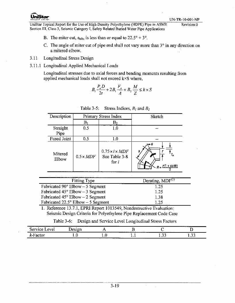
UnLStarRUN-TR- 10-001-NP
UniStar Topical Report for the Use of High Density Polyethylene (HDPE) Pipe in ASMESection III, Class 3, Seismic Category I, Safety Related Buried Water Pipe Applications
Revision:0
3.11
3.11.1
B. The miter cut, alIb, is less than or equal to 22.5' + 3'.
C. The angle of miter cut of pipe end shall not vary more than 3' in any direction ona mitered elbow.
Longitudinal Stress Design
Longitudinal Applied Mechanical Loads
Longitudinal stresses due to axial forces and bending moments resulting fromapplied mechanical loads shall not exceed kxS where,
PD F, MB1 PaD+ 2B1 B M<2t A Z
Table 3-5: Stress Indices, B1 and B2
Description Primary Stress Index Sketch3B1 B 2
Straight 0.5 1.0 --
PipeFused Joint 0.5 1.0 --
Mitered 0.75 xix MDF +0rtn
Elbow 0.5 x MDF See Table 3-8
for i • R = r(I + cotO)2
Fitting Type Derating, MDFý1)Fabricated 90' Elbow - 5 Segment 1.25Fabricated 450 Elbow - 3 Segment 1.25Fabricated 45' Elbow - 2 Segment 1.38Fabricated 22.50 Elbow - 5 Segment 1.251. Reference 13.7.1, EPRI Report 1013549, Nondestructive Evaluation:
Seismic Design Criteria for Polyethylene Pipe Replacement Code Case
Table 3-6: Design and Service Level Longitudinal Stress Factors
Service Level Design A B C Dk-Factor 1.0 1.0 1.1 1.33 1.33
3-19

UniStarNUCLEAR..NERGY UN-TR-10-001-NP
UniStar Topical Report for the Use of High Density Polyethylene (HDPE) Pipe in ASME Revision:0Section III, Class 3, Seismic Category I, Safety Related Buried Water Pipe Applications
3.11.2 Short Duration Longitudinal Applied Mechanical Loads
For the assessment of short duration loads (less than five minutes), the allowablestress, S, is replaced by one of the two following alternatives,
A. 40% of the tensile strength at material yield, or
B. The values in Table 3-7.
Table 3-7: Short Duration (< 5 minutes) Allowable Longitudinal Tensile Stress Values
Temp, 'F < 70 100 120 140 176S, psi 1200 940 770 630 400
3.12 Temperature Design
3.12.1 Minimum Temperature
The PE material brittleness temperature shall not be warmer than -88°F when testedin accordance with ASTM D746 as required by ASTM D3350. System designtemperatures shall not be less than 207F.
3.12.2 Design for Expansion and Contraction
A. Fully Constrained Thermal Contraction
The stress resulting from the assumption of fully constrained thermal contractionof the buried pipe when Twater < Tground, increased by the tensile stress due to axialcontraction from Poisson effect, shall not exceed the allowable stress S.
ar = Epipe xa xAT-vx P •D 8
For fully constrained thermal expansion and contraction evaluations thecalculated thermal stresses are based on the temperature differential between thepipe operating temperature and the soil temperature.
B. Fully Constrained Thermal Expansion
The tensile stress resulting from the assumption of fully constrained thermalexpansion of the buried pipe when Twater > Tground, shall not exceed the allowablestress S.
r =Epipe×xaxAT<S
C. Alternative Thermal Expansion or Contraction Evaluation
As an alternative to the above equations, the soil stiffness may be accounted forto calculate pipe expansion and contraction stresses. If the alternate thermalexpansion and contraction evaluation is performed in the final analysis, the rangeof moments for the expansion and contraction cases will be evaluated instead ofevaluating the expansion and contraction cases. The stresses shall satisfy thefollowing equation:
3-20

UniStar"NUCLEAR ENERGY UN-TR-10-001-NP
UniStar Topical Report for the Use of High Density Polyethylene (HDPE) Pipe in ASME Revision:0Section III, Class 3, Seismic Category I, Safety Related Buried Water Pipe Applications
iMc + Fac •l 1lOOpsiZ. A
Table 3-8: Stress Intensification Factors, i
Fitting or Joint iStraight Pipe 1.0Butt Fusion 1.0Mitered Elbow 2.21Flange 1.0
Note 1: See Reference 13.7.4
A property that distinguishes PE pipe from metallic pipe is that its linearcoefficient of thermal expansion is about ten times larger. This means a largerthermal expansion/contraction in the case of unconstrained pipe. Anotherdistinguishing property is a much lower apparent modulus of elasticity. In thecase of constrained buried pipe, this leads to a much lower value of thermallyinduced longitudinal stresses.
Due to its relatively high thermal expansion coefficient and poor thermalconductivity, a small thermal gradient in the radial direction will exist in thethick wall of an HDPE pipe.
A Finite Element Analysis (FEA) model of a portion of the largest HDPE pipewill be performed and any internal moments created by the radial thermalgradient stresses are added to the alternative thermal expansion equation todemonstrate that the thermal gradient stresses across the pipe wall are acceptable.
A minimum 3 feet of soil cover is provided over the top of piping for freezeprotection. Soil is a poor conductor of heat, and it serves to insulate the pipefrom low ambient temperatures. This insulating property of soil also serves tominimize the temperature gradient (and reduce thermal stresses) through theHDPE pipe wall of hot water pipes (1 150F to 140'F water temperatures), as thereis a significant temperature gradient through the backfill surrounding the pipe.
For very thick pipe walls, the surface temperature at the OD of a hot HDPE pipeis estimated to be 80°F to 90'F (not the lower 60°F associated with cold waterpipes), and the surface temperature is even higher for thinner wall hot pipes.When operating with 11 5°F water the radial temperature gradient for a thick wallpipe is 250F to 35°F (not 55°F for a 60'F surface temperature). This shows that aburied pipe's higher surface temperature will reduces its radial temperaturegradient and the associated radial stress.
3.13 Non-repeated Anchor Movements
The effects of any single non-repeated anchor movements shall meet the followingequation:
iM2 + FaD < 2S
Z A
3-21

UniStar"NUCLEAR ENERGY UN-TR-10-001-NP
UniStar Topical Report for the Use of High Density Polyethylene (HDPE) Pipe in ASME Revision:0Section III, Class 3, Seismic Category I, Safety Related Buried Water Pipe Applications
3.14 Soil and Surcharge Loads
3.14.1 Ring Deflection
The soil and surcharge loads on a buried HDPE piping system shall not cause achange in pipe outside diameter as a percentage of the average outside diameter, D,beyond a limit nmax, where:
1 KxLxPE +KxPL144 2EPipe DR -1 + .61xFsxEx + 0.061xFs xE'3 DR-1I
Epipe is per Table 3-11 based on the system design life and
PE = Psaturated X HW + Pdry x (H - Hw)
Table 3-9: Maximum Allowable Ring Deflection PE
DR17.015.513.5119
7.36.0
Q..x(%)6.06.06.05.04.03.01.5
Table 3-10: Soil Support Factor, Fs
BdID, ft/inEVN/E
0.10.20.40.60.81.01.52.03.05.0
1.5
0.150.300.500.700.851.001.301.501.752.00
2.00.300.450.600.800.901.001.151.301.451.60
2.50.600.700.800.900.951.001.101.151.301.40
3.0B d/D, f!/in0.80
0.850.900.950.981.001.051.101.201.25
3.04.0
0.900.920.951.001.001.001.001.051.081.10
5.01.001.001.001.001.001.001.001.001.001.00
3-22
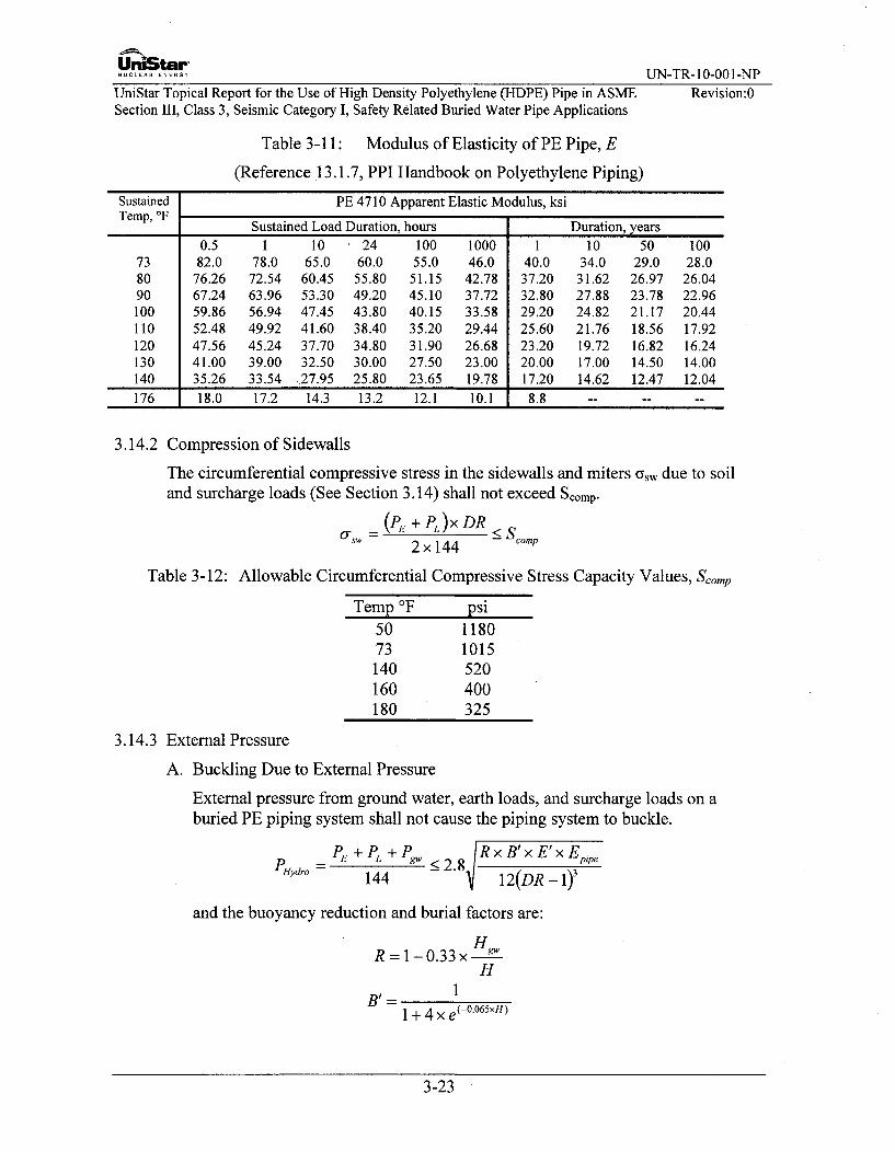
Uni~Mr"NUCLEAR ENERGY UN-TR- 10-001-NP
UniStar Topical Report for the Use of High Density Polyethylene (HDPE) Pipe in ASMESection III, Class 3, Seismic Category I, Safety Related Buried Water Pipe Applications
Revision:0
Table 3-11: Modulus of Elasticity of PE Pipe, E
(Reference 13.1.7, PPI Handbook on Polyethylene Piping)
Sustained PE 4710 Apparent Elastic Modulus, ksiTemp, T Sustained Load Duration, hours Duration, years
0.5 1 10 24 100 1000 1 10 50 10073 82.0 78.0 65.0 60.0 55.0 46.0 40.0 34.0 29.0 28.080 76.26 72.54 60.45 55.80 51.15 42.78 37.20 31.62 26.97 26.0490 67.24 63.96 53.30 49.20 45.10 37.72 32.80 27.88 23.78 22.96100 59.86 56.94 47.45 43.80 40.15 33.58 29.20 24.82 21.17 20.44110 52.48 49.92 41.60 38.40 35.20 29.44 25.60 21.76 18.56 17.92120 47.56 45.24 37.70 34.80 31.90 26.68 23.20 19.72 16.82 16.24130 41.00 39.00 32.50 30.00 27.50 23.00 20.00 17.00 14.50 14.00140 35.26 33.54 27.95 25.80 23.65 19.78 17.20 14.62 12.47 12.04176 18.0 17.2 14.3 13.2 12.1 10.1 8.8 -- -- --
3.14.2 Compression of Sidewalls
The circumferential compressive stress in the sidewalls and miters aw due to soiland surcharge loads (See Section 3.14) shall not exceed Scomp.
(P, + PL)x DR < C
2 x 144 -comp
Table 3-12: Allowable Circumferential Compressive Stress Capacity Values, Scomp
Temp 'F psi50 118073 1015140 520160 400180 325
3.14.3 External Pressure
A. Buckling Due to External Pressure
External pressure from ground water, earth loads, and surcharge loads on aburied PE piping system shall not cause the piping system to buckle.
PHydro =E + PL + Pg" 2 R x B'x E'x Epipe144 2 12(DR-1)'
and the buoyancy reduction and burial factors are:
HR =1-0.33x
H
11 + 4 xe-°6×N
3-23

NUCLE AR EUN-TR- 10-001-NP
UniStar Topical Report for the Use of High Density Polyethylene (HDPE) Pipe in ASME Revision:OSection III, Class 3, Seismic Category I, Safety Related Buried Water Pipe Applications
B. Effects of Negative Internal Pressure
When the pipe is subject to a negative internal pressure, it shall withstand thedifferential pressure without credit for the surrounding soil.
Al) < f° 2Epp ('
- 1v2(DR-
Table 3-13: Ovality Correction Factor, f0
Percent-Ovality Ovality Correction Factor
1% 0.912% 0.843% 0.765% 0.646% 0.52
3.14.4 Flotation
Buried PE piping system shall have sufficient cover to prevent flotation bygroundwater. For the U.S. EPRTM to be built by UniStar Nuclear Energy or itspartners, the piping will be buried with no anchors. The upward resultant force dueto buoyancy on a buried pipe in saturated soil is:
WW <WP + PE D--w <w ±~12
3.14.5 Surface Loads (AASHTO Vehicle Loading)
3.14.6 Vehicular loads are based on the American Association of State Highway andTransportation Officials standard truck loads. For calculating the soil pressure onthe PE pipe, the loading is assumed to be an H-20 (HS-20) truck with a total weightof 40,000lbs. The weight is distributed with 8,000lbs on the front axle and 32,000lbson the rear axle. The HS-20 has the same axle loadings as the H-20, but the HS-20has two rear axles. For these trucks, the maximum wheel load is found at the rearaxle(s) and equals 40% of the total weight of the truck. The maximum wheel load isused to represent the static load applied by either single or double axles.
A. Impact factor
Impact load is determined by multiplying the static wheel load by an impactfactor. Table 3-14 gives impact factors for vehicles on paved roads. Forunpaved roads, impact factors of 2.0 or higher may occur, depending on roadsurface.
3-24
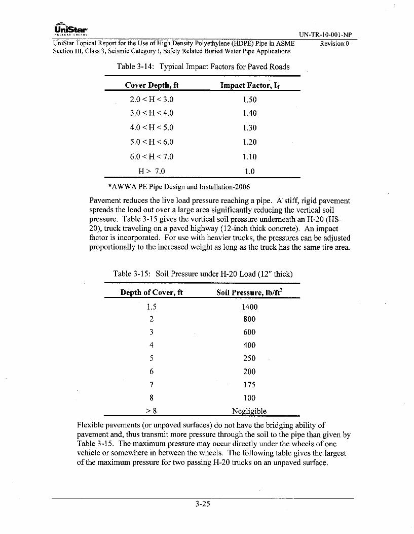
UniStar-NUCLEAR ENERGY UN-TR-10-001-NP
UniStar Topical Report for the Use of High Density Polyethylene (HDPE) Pipe in ASME Revision:0Section III, Class 3, Seismic Category I, Safety Related Buried Water Pipe Applications
Table 3-14: Typical Impact Factors for Paved Roads
Cover Depth, ft Impact Factor, If
2.0 < H < 3.0 1.50
3.0 < H < 4.0 1.40
4.0 < H < 5.0 1.30
5.0 < H < 6.0 1.20
6.0 < H < 7.0 1.10
H > 7.0 1.0
*AWWA PE Pipe Design and Installation-2006
Pavement reduces the live load pressure reaching a pipe. A stiff, rigid pavementspreads the load out over a large area significantly reducing the vertical soilpressure. Table 3-15 gives the vertical soil pressure underneath an H-20 (HS-20), truck traveling on a paved highway (12-inch thick concrete). An impactfactor is incorporated. For use with heavier trucks, the pressures can be adjustedproportionally to the increased weight as long as the truck has the same tire area.
Table 3-15: Soil Pressure under H-20 Load (12" thick)
Depth of Cover, ft Soil Pressure, lb/ft2
1.5
2
3
4
5
6
7
8
>8
1400
800
600
400
250
200
175
100
Negligible
Flexible pavements (or unpaved surfaces) do not have the bridging ability ofpavement and, thus transmit more pressure through the soil to the pipe than given byTable 3-15. The maximum pressure may occur directly under the wheels of onevehicle or somewhere in between the wheels. The following table gives the largestof the maximum pressure for two passing H-20 trucks on an unpaved surface.
3-25

UrtiStar-NUCEAR EUN-TR-10-001-NP
UniStar Topical Report for the Use of High Density Polyethylene (HDPE) Pipe in ASME Revision:0Section 1II, Class 3, Seismic Category I, Safety Related Buried Water Pipe Applications
Table 3-16: Soil Pressure under H-20 Load (unpaved or flexible pavement)
Depth of Cover, ft Soil Pressure, lb/ft2
1.5
2
2.5
3
3.5
4
6
8
10
> 10
2000
1370
1000
780
620
520
290
190
120
Negligible
Railroad Loads
The live loading configuration used for pipes under railroad is the Copper E-80loading, which is an 80,0001b load that is uniformly applied over a 3' x 8' area on5ft centers. The area represents the 8ft width of and the spacing betweenlocomotive drive wheels. Live loads are based on the axle weight exerted on thetrack by two locomotives and their tenders coupled together in double headerfashion.
Table 3-17: Live Load Pressure for E-80 Railroad Loading
Depth of Cover, ft Soil Pressure, lb/ft2
2.5
3.0
4.0
5.0
6.0
7.0
8.0
9.0
10.0
20.0
2780
2650
2420
2175
1930
1720
1530
1368
1209.6
475.2
Live loads such as those imposed by trucks, rail, and construction equipment or otherconstruction conditions will be considered in the analysis and design. The pressuretransmitted to the buried pipe under these loads is computed as follows:
3-26

UniStar-............. UN-TR-10-001-NP
UniStar Topical Report for the Use of High Density Polyethylene (HDPE) Pipe in ASME Revision:0Section III, Class 3, Seismic Category I, Safety Related Buried Water Pipe Applications
PP =0.48 P ]
Where
P = surface load transmitted to the buried pipe, psid = offset distance from the surface load to buried pipe, in.H = thickness of soil cover above the pipe, in.P, = concentrated surface load, lbs.
The magnitude of Pp above is multiplied by an impact factor. The magnitude of Ppmay be taken from Tables 3-14, 3-15, and 3-16 which is based on AASHTO HS-20Truck and Copper E-80 railroad loads.
3.15 Seismic Design - Seismic Induced Stresses
Seismic-induced damage to buried pipe is largely due to wave propagation orpermanent ground deformation resulting from landslides, fault movement, andliquefaction-induced lateral spread. Seismic anchor movements are taken intoaccount where the piping enters a building or structure. For the case of pipinganchored to an adjacent building, strain development due to settlement of thebuilding should be evaluated. The seismic effects on buried piping are self limitingin that strains are limited by the surrounding soil. Therefore, the stresses due tothese strains are secondary in nature.
The stresses in the buried PE piping system due to soil strains caused by seismicwave passage and building seismic anchor motion effects are evaluated. The stressesshall satisfy the following equation:
iME + FaE < 1100psi
Z A
Seismic wave passage, seismic soil movement, and building seismic anchor motionloads are combined by square root sum of the squares. Section 4.1.2 provides amethod for the analysis of seismic wave passage, seismic soil movement, andbuilding seismic anchor motion effects.
3.16 Flange Joint Evaluation
PE to steel flanged joints are used. The maximum sustained pressure that the flangejoint can be subjected to is a 320psig hydro test pressure (for a 200psig designpressure). The flange joint shall also be designed to accommodate the transientsurge pressures specified in Section 3.10.4.
3-27

UrniStar-NUCLEAR ENERGY UN-TR-10-001-NP
UniStar Topical Report for the Use of High Density Polyethylene (HDPE) Pipe in ASME Revision:0Section III, Class 3, Seismic Category I, Safety Related Buried Water Pipe Applications
3.16.1 HDPE to Steel Flanges
The PE to steel flanges are demonstrated to have adequate capacity if therequirements of Section 3.10.6 are met for the flange connection, and therequirements of Section 8.6 are met at the fusion joint connecting the PE pipe to thePE flange adapter, and the flange joint is installed in accordance with therequirements of Section 7.5.2:
A. The flange bolt torque requirements specified in Section 7.5.2.F is met.
B. Material for the flange joint bolting shall be carbon steel SA-307 Grade B, aslisted in ASME Section II, Part D, Subpart 1, Table 3, for Section III, Class 3piping bolting materials.
C. Steel flanges are Class 150 flat faced flanges conforming to the requirements ofASME Section III and ASME B 16.5 or B 16.47 as applicable.
3-28

UniStar"NUCLEAR ENERGY UN-TR-10-001-NP
UniStar Topical Report for the Use of High Density Polyethylene (HDPE) Pipe in ASME Revision:0Section III, Class 3, Seismic Category 1, Safety Related Buried Water Pipe Applications
4.0 PIPING ANALYSIS METHODS
4.1 Seismic Analysis Input for Buried Piping
There are two potential sources for seismic loads on the piping: loads from wavepropagation in the soil and from seismic anchor motion (SAM) of the anchor thatforms the boundary for the buried pipe. Sections 4.1.1 and 4.1.2 present themethodology for calculating the loads from these sources. Because the loads andstresses from these two sources are independent, they are calculated separately andcombined using the square root sum of the squares (SRSS) method.
4.1.1 Seismic Anchor Movements
The effects of differential displacements of structures, greater than 1/16", to whichthe piping system attaches during an SSE are considered. The maximum relativedisplacement for each anchor location is obtained from the results of the structuralanalysis for the supporting structure or calculated from the applicable floor response.These movements will be applied to the short run of metal piping from the buildingto the connection to the HDPE pipe. While these movements are not directly loadingthe HDPE pipe, there is still some effect on the HDPE pipe from these buildingmovements.
If the relative displacement between locations is small (less than 1/16") the anchormovement will not be required for the stress analysis.
The analysis of these seismic anchor motions (SAMs) will be performed as a staticanalysis. The results of this analysis are combined with the piping system seismicinertia analysis results by absolute summation when an enveloped uniform supportmotion is used for the dynamic analysis, per Standard Review Plan (NUREG-0800)Section 3.7.3.
The anchor location cannot be located directly at the HDPE/steel flange, and must belocated on the adjacent steel piping. This portion of piping will be unburied. Thecombined anchor design loads are determined in the above ground piping analysisusing traditional pipe stress analysis software. To determine the anchor loads, acomputer model is used for the unburied portion of metallic piping and the modelwill include the weight of the metallic piping from the anchor point to theHDPE/steel interface flange. The model will also include a lumped mass at the endof the metallic piping that bounds the total weight of the HDPE flange, steeltransition flange and metallic backing ring.
4.1.2 Analysis for the Effects of Seismic Wave Passage Through Soil
The buried pipe will be qualified by analysis for the effects of seismic wave passageas follows:
Step 1: The strains from seismic wave passage, and seismically-induced permanentor temporary movements are obtained by a site-specific geotechnical/civilinvestigation.
4-1

UniStar'............. UN-TR-10-001-NP
UniStar Topical Report for the Use of High Density Polyethylene (HDPE) Pipe in ASME Revision:0Section III, Class 3, Seismic Category I, Safety Related Buried Water Pipe Applications
Step 2: The soil strains are converted into an equivalent temperature rise of theburied pipe, as follows:
ATeq = 0soil
Step 3: The pipe-soil system is modeled as a piping system constrained by soilsprings.
(a) The pipe model will consider two cases: short-term modulus (<10 hours,Table 3-11) for wave passage and long-term modulus for permanent soilmovement (permanent seismic anchor motion).
(b) The soil model will have at least a bi-linear stiffness, and shall considertwo cases: upper and lower bound of soil stiffness.
Refer to ASCE, Guidelines for the Seismic Design of Oil and Gas PipelineSystems, 1984, and ASCE 4 Seismic Analysis of Safety-Related NuclearStructures and Commentary, or American Lifelines Alliance, Guidelines forthe Design of Buried Steel Pipes, July 2001 ,with February 2005 addendum.
Step 4: The equivalent rise of temperature, ATeq is applied to the pipe-soil model toobtain forces and moments throughout the system.
Step 5: The anticipated building seismic anchor movements are applied to the pipe-soil model to obtain forces and moments throughout the system.
Step 6: The anticipated seismic movements are applied to the pipe-soil model toobtain forces and moments throughout the system.
Step 7: The results of Steps 4, 5, and 6 are combined by Square Root Sum of Squares(SRSS), at each point along the piping system to obtain resultant forces andmoments.
Step 8: The resultant forces and moments are evaluated as follows:
(a) The axial stresses in pipe, fittings and fused joints shall comply with therequirements of Section 3.11.
(b) Alternatively, the seismic induced strain is determined as follows
laEI+ vPD
('a )Earthquake = E
This strain, (&a)Eathquae is limited to the values listed in Table 4-1, where k, thedesign and Service Level longitudinal stress factors, is defined in Table 3-6.
4-2

UniStar-NUCLEAR ENERGY n rN-TR- 10-001-NP
UniStar Topical Report for the Use of High Density Polyethylene (HDPE) Pipe in ASME Revision:0Section III, Class 3, Seismic Category I, Safety Related Buried Water Pipe Applications
Table 4-1: Seismic Strain Limits
DR Allowable Strain
DR•_ 13.5 0.025 x k.13.5 < DR•_21 0,020 x KDR> 21 0.017 x k
4.2 Response Spectrum Seismic Analysis Method for the Combined System.
For the portion of unburied HDPE piping in a yard vault or in the building, theeffects of the ground motion during an SSE event that are transmitted throughstructures and soil to the piping systems at anchorage locations, is considered. Theresponse spectrum method of analysis, peak values of response are determined foreach mode of the piping system by application of floor response spectra, whichrepresent the maximum acceleration response of an idealized single-degree-of-freedom damped oscillator as a function of natural frequency to the vibratory inputmotion of the structure. If the stresses due to seismic loads can be evaluated and*shown to be small, it may be excluded from the analysis: however, if the loads in theunburied portion of HDPE pipe are significant, the stresses in the unburied portion ofHDPE pipe are evaluated as follows:
The seismic analysis for a combined system (Steel and HDPE) is conducted asfollows:
A. For the non-buried piping, Multiple Input Response Spectra Modal analysis isconducted for the SSE case. The seismic response spectrum is input for theabove ground piping and null spectra (a spectra with zero spectral acceleration)is input for the buried pipe. The piping software shall then obtain theinteractions between the unburied steel portion of pipe and buried portion of thepiping. The intermodal and interspatial combinations are combined by thesquare root sum of the squares (SRSS). Inter-group combinations are combinedusing the SRSS. The combination of the equivalent seismic (thermal) andresponse spectrum (with null spectrum) analysis will be combined using SRSS.
B. For the buried pipe, an equivalent ATeq is calculated per Section 4.1.2. This ATeqis then applied to the buried piping section only.
C. The results from A) and B) above are summed by the SRSS to obtain the totalseismic response of a combined system.
4-3

UniStar-.C.A -..EG. UN-TR-10-001-NP
UniStar Topical Report for the Use of High Density Polyethylene (HDPE) Pipe in ASME Revision:0Section III, Class 3, Seismic Category I, Safety Related Buried Water Pipe Applications
4.3 Analysis Inputs
4.3.1 Design Loads
Bounding Design temperature and pressure values are used as input to thecalculations.
Table 4-2: Bounding Design Conditions
Design Pressure up to 200psig
Design Temperature up to 140°F*
• Including a temperature excursion up to 160'F for 30 days.
4.3.2 Pipe Properties
Outside Pipe Diameter, OD, thickness and weight values for HDPE pipe are takenfrom standard piping catalogs. The following pipe properties are used anddocumented in the piping analysis:
1. Nominal Size2. Material3. Schedule4. Outside Diameter, OD, in.5. Wall thickness, in6. Contents, (water)7. Weight of contents, lb/ft8. Weight of pipe, lb/ft
4.4 HDPE to Steel Interface
The HDPE flange interface shall have the option to be located in a yard vault orinside the building. If the yard option is selected, the steel piping shall utilize anembedment penetration for the steel piping; this will serve as an anchor and aboundary for the piping analysis. The anchor point in the building or in a vault isdesigned to stop all forces and moments. The HDPE pipe, at a minimum mustcontain a seal to prevent ground water from entering the vault or the building. Thelength of unburied HDPE pipe is minimized, as reasonably achievable, to minimizethe stresses due to seismic inertia.
All transitions from steel pipe to PE pipe require a flanged connection. On the metalportion of piping, an ASME B 16.5 or ASME B 16.47 flange must be welded to thepipe. On the PE portion of the transition, a lap joint type flange adapter is fused tothe plastic pipe. A special steel backing flange will be used on the back of the PEflange adapter and must conform to the same ASME B 16.5 or ASME B 16.47 patternas the welded steel flange. The stress intensification factors are listed in Table 3-8.
4-4

UniStar-............. UN-TR-10-001-NPUniStar Topical Report for the Use of High Density Polyethylene (HDPE) Pipe in ASME Revision:0Section III, Class 3, Seismic Category I, Safety Related Buried Water Pipe Applications
4.5 Modeling of PE Elbows
PE elbows include 300, 450, and 90' elbows, modeled as mitered bends. The 300bend consists of two segments, the 450 bend consists of three segments, and the 90'bend consists of five segments. The maximum miter angle is 22.5'. The segmentlengths for the 30' bend and the 450 bend are comprised of equal segment lengths.See Figure 3-1(a) & (b) for a sketch which shows how the segments are divided for a900 bend:
4.6 Stress Intensification Factors (SIFs)
Many computer programs automatically calculate SIFs and stress indices based onthe ASME Code, which is coded into the software. The buried PE piping evaluationcriteria is not programmed into any currently available software. The calculationsfor the buried PE piping can be done by performing a manual calculation orperforming a manual calculation using data extracted from the computer software.The Stress Intensification Factors and stress indices can be input into most pipestress programs, and are taken from Table 3-5 and Table 3-8.
4.7 Soil Springs
The buried section of the piping is subject to loads from earthquakes, temperaturedifferential, and surrounding soil. Details on how the soil springs are calculated areprovided in Section 5.4.2. Spring stiffness is based on the local coordinate system ofthe pipe in the axial, vertical, and transverse directions. These springs must bespaced along the piping at an appropriate spacing. The spacing must be denseenough to model the behavior of the piping while keeping the model to amanageable size. Unlike flexible above ground piping, most of the movements inburied piping are absorbed within a short distance (the influence length LO) ofchanges in direction.
Within the influence length, soil springs may be spaced at a distance Li ofapproximately 2D, with individual spring stiffness Ks-oi, s-j. Beyond the influencelength, the springs may be spaced at larger distances Li such as 1OD. This is shownschematically in Figure 5-6. In addition, beyond the influence length, three soilsprings are spaced at a length of 2D on each side of any changes in piping direction.Examples of this are shown in Figure 5-7.
Soil springs can be modeled in a computer program first by creating three shortmembers in the orthogonal directions of the pipe. The members are anchored at theendpoint and the appropriate stiffness is applied. The stiffnesses are calculated inthe axial, transverse, and vertical directions.
4-5

UniStar-NULERNG UN-TR- 10-001-NP
UniStar Topical Report for the Use of High Density Polyethylene (HDPE) Pipe in ASME Revision:0Section III, Class 3, Seismic Category I, Safety Related Buried Water Pipe Applications
4.8 Analysis of the Above Ground Metal Piping
In some instances, the anchor cannot be located at the building wall to completelyisolate piping inside the building from the buried piping because of differentialsettlement or seismic anchor motion effects. In these cases the analysis methodologywill include a portion of underground piping interacting with non-buried pipinginside the building.
The piping analysis for the above ground steel Class 3 piping shall comply with the2001 Edition through 2003 Addenda of ASME BPVC, Section III, Division 1, ND-3600 as described in Section 2.1.
4.9 Design Report (Stress Analysis Report)
The piping stress analysis Design Report shall have the same requirements as steelpipe. The Design Report is separate from the above ground steel piping. The designreport shall include methodology, stress analysis inputs, relevant assumptions,computer codes and manual calculations, results, and conclusions that were used toqualify the use of HDPE.
The Design Report shall be stamped by a qualified Professional Engineer who has atleast 18 months of experience with ASME Section III Class 3 piping as well as somerelevant experience/knowfedge of HDPE piping systems.
4-6

UniStarNUCLE E-.... UN-TR-10-001-NP
UniStar Topical Report for the Use of High Density Polyethylene (HDPE) Pipe in ASME Revision:0Section III, Class 3, Seismic Category I, Safety Related Buried Water Pipe Applications
5.0 PIPING MODELING TECHNIQUES
5.1 Methodology and Approach
The piping system is analyzed using a combination of manual calculations andcomputer code. Piping analysis software that is used must be verified and validatedin accordance with the Certificate Holder's Quality Assurance Program. The pipinganalysis software analyzes the complex piping systems subjected to static anddynamic loads. The basic load case (deadweight, pressure, thermal, seismic, SSE,etc.) and their combinations are included in the computer analysis.
Stresses in steel pipe can be automatically calculated by the computer softwareaccording to the pertinent ASME Code year; however, computer software does notcurrently calculate the stresses for all piping load cases and combinations for HDPEpipe since HDPE material properties and qualification criteria have not beenincluded in these software packages. Consequently, manual calculations areperformed for HDPE piping in accordance with this Topical Report.
5.1.1 Steel Pipe Criteria
The steel pipe, which extends from the building anchor to the HDPE pipe flangeconnection, is qualified using the computer software in accordance with theapplicable codes.
5.2 Structural Boundaries
The model of a piping system typically begins and ends at anchor points, such asstiff equipment nozzles or fully constrained wall penetrations. These are points thateffectively restrain all six degrees of freedom. If there are no anchors, the modelcould become very large and difficult to analyze. The boundaries required in thisTopical Report will be on the metal side of the HDPE/steel interface.
5.3 Flexibility of Mitered Elbow Fittings
The response of a piping system due to a dynamic excitation, such as an earthquake,depends on the system's natural frequencies, which, in turn, depend on the flexibilityof its fittings (tees, elbows, bends, etc.). The flexibility of fittings must therefore becorrectly modeled. The flexibility of a pipe fitting is defined by a flexibility factor"k" (not to be confused with Service Level Factor) provided in the ASME Code, andis automatically calculated in piping analysis computer codes. The flexibility factoris used to calculate the SIFs and Stress Indices for the fitting. As noted in Section4.6, specific SIF values for HDPE mitered elbows are given in Table 3-5 and Table3-8. These tables cover all fittings allowed by this Topical Report except for flangeadapters which have an SIF of 1.
5.4 Soil Springs
5.4.1 Soil Spring and Break Away Displacement
5-1
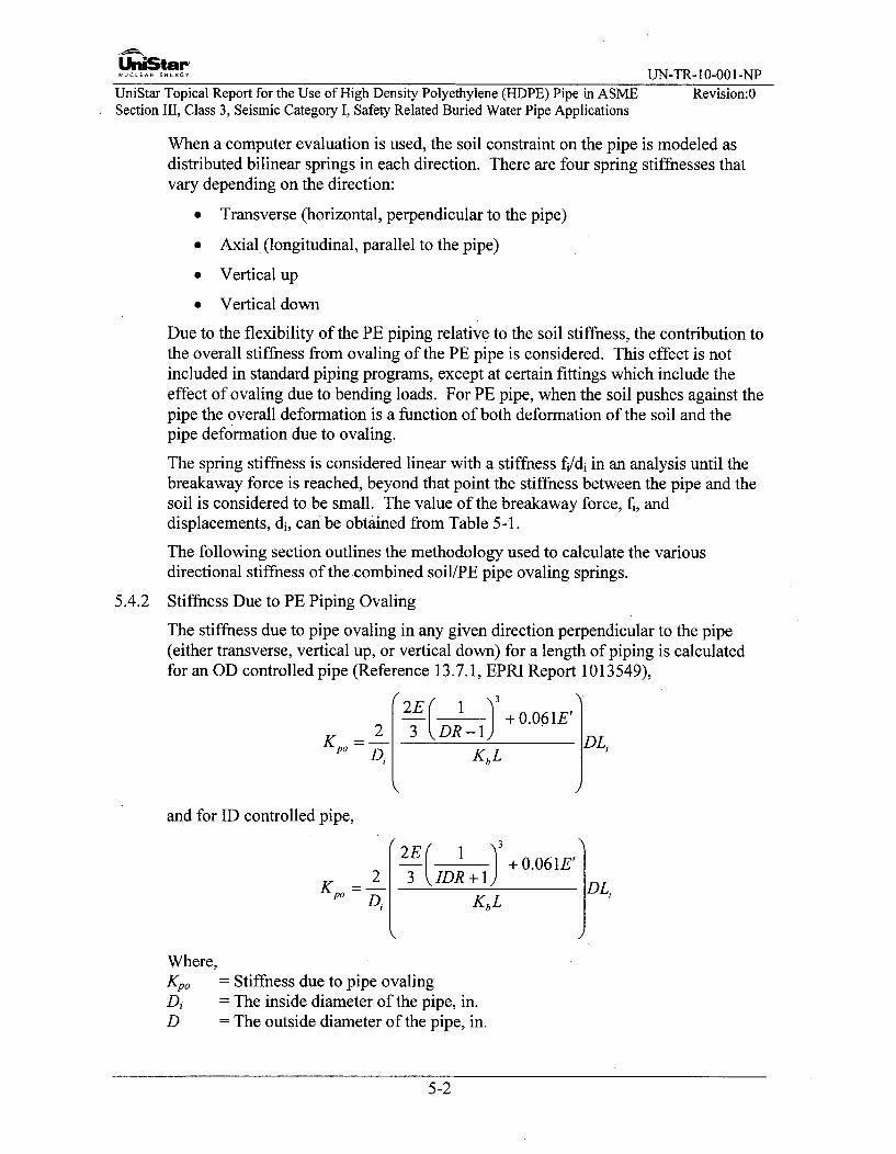
UniStar....... ENERGY UN-TR-10-001-NP
UniStar Topical Report for the Use of High Density Polyethylene (HDPE) Pipe in ASME Revision:0Section III, Class 3, Seismic Category I, Safety Related Buried Water Pipe Applications
When a computer evaluation is used, the soil constraint on the pipe is modeled asdistributed bilinear springs in each direction. There are four spring stiffnesses thatvary depending on the direction:
" Transverse (horizontal, perpendicular to the pipe)
" Axial (longitudinal, parallel to the pipe)
" Vertical up
" Vertical down
Due to the flexibility of the PE piping relative to the soil stiffness, the contribution tothe overall stiffness from ovaling of the PE pipe is considered. This effect is notincluded in standard piping programs, except at certain fittings which include theeffect of ovaling due to bending loads. For PE pipe, when the soil pushes against thepipe the overall deformation is a function of both deformation of the soil and thepipe deformation due to ovaling.
The spring stiffness is considered linear with a stiffness fi/di in an analysis until thebreakaway force is reached, beyond that point the stiffness between the pipe and thesoil is considered to be small. The value of the breakaway force, fi, anddisplacements, di, can be obtained from Table 5-1.
The following section outlines the methodology used to calculate the variousdirectional stiffness of the combined soil/PE pipe ovaling springs.
5.4.2 Stiffness Due to PE Piping Ovaling
The stiffness due to pipe ovaling in any given direction perpendicular to the pipe(either transverse, vertical up, or vertical down) for a length of piping is calculatedfor an OD controlled pipe (Reference 13.7.1, EPRI Report 1013549),
+o.061E'
=" D--- KbL
and for ID controlled pipe,
~2E 1 3 +O0.061E'jýK 2o 3 IDR + 1 DL,
KKbL
Where,Kpo 0 = Stiffness due to pipe ovalingDi -- The inside diameter of the pipe, in.D = The outside diameter of the pipe, in.
5-2

UniStar'NUCLEAR ENERGY UJN-TR-10-001-NP
UniStar Topical Report for the Use of High Density Polyethylene (HDPE) Pipe in ASME Revision:0Section III, Class 3, Seismic Category I, Safety Related Buried Water Pipe Applications
DR = Pipe Dimension Ratio, DR=D/tIDR = Pipe Dimension Ratio for ID controlled pipe, IDR =D/tKb = The bedding factor, usually 0.1L = The deflation Lag Factor, (1.0 recommended for seismic loads and 1.5 for
thermal loads)El = The soil reaction modulus, psiE = The pipe elastic modulus, psi, use short term modulus for seismic, and
1000 hr. modulus for thermal loadsLi = Effective length of piping modeled by discrete spring
The stiffness is based on one-half of the deflection of the ring and calculates thestiffness (in/lb) for a discrete spring of this effect that is distributed along the lengthand diameter of the pipe.
5.4.3 Soil Spring Calculation Method #1
This methodology models the soil stiffness in the transverse (horizontal,perpendicular to the pipe), vertical up, and vertical down directions. This willcalculate k, the vertical modulus (psi) of subgrade reaction, kh the horizontalmodulus (psi) of subgrade reaction, and kij the orthogonal soil spring (lb/in) in thepipe. The effect of the axial friction force on the pipe is modeled in Appendix VII ofASME B3 1.1 by applying a force that is defined as Ff, the total friction force at thechanges in direction of the pipe.
When using this method kv and kh are the parameters for K in defining the ovalingstiffness. The stiffness used for the combined soil/pipe ovaling that should bemodeled is defined using the springs in series as follows (Reference 13.7.1, EPRIReport 1013549):
1 1 1
Ks-oi's-oj Kpo KY
Where,
Ks-oi,s-oj = Combined soil-ovaling spring in a given direction,
Kpo = spring due to pipe ovaling calculated in Section 5.4.2
Kij. = spring stiffness in a given direction calculated using the methodology inASME B3 1.1, Appendix VII.
5.4.4 Soil Spring Calculation Method #2
The piping may be modeled using soil springs in all four directions, transverse(horizontal, perpendicular to the pipe), axial to the pipe, vertical up and verticaldown, using the equations provided in ASCE guidelines for oil and gas transmissionlines. Table 5-1 provides equations for fi (force in a given direction) and di(displacement in a given direction), which are taken from ASCE guidelines.
5-3

UniiStar-NUCLEA.ENERGY UN-TR- 10-001-NP
UniStar Topical Report for the Use of High Density Polyethylene (HDPE) Pipe in ASME Revision:0Section III, Class 3, Seismic Category I, Safety Related Buried Water Pipe Applications
Table 5-1: Equations to Calculate the Breakaway Forcef, and Displacement di
Soil Transverse Spring Axial Spring Vertical Down Spring Vertical Up Springft/dt fa/da fa/da fu/du
Sand f = DsiH X Nqh fa =(rD / 2)As, fd =y, oHNqD + r,"j1 D2Ny/2 f, = DTY o1 HXNqv
d,= 2% to10% H(l + Ko)tan5 dd =10% to15%D dd= 0.5% to1.5%D(H+D/2) da= 0. 1 in. to
0.2 in.
Clay f = DSuNh f. = ;DC. fd = 5.14DS. fu =DyoiH x N0 v
dt= 3% to 5% da= 0.2 in. to dd = 10% to 15%D dd= 10% to 20%D(H+D/2) 0. 4 in.
where:
D = Outer Diameter of the pipe, in.di = Displacement, in.f = Breakaway force, lby,'oi = Density of soil, lb/in3
H = Height of the soil, in.Nqh = Horizontal capacity factor for sand (varies with H/d and o, refer to Figure 5-1.)K& = Coefficient of soil pressure at rest (0.5 to 1.0)6i = Friction angle pipe-soil (deg), 6 clay = 0, 6 sand = 0.5o to 0.8 oNqv = Vertical up-bearing capacity factor for sand (varies with H/d and o, refer to
Figure 5-4)N, = Vertical up-bearing capacity factor for clay (varies with H/d, refer to Figure 5-5)Nq = Downward bearing capacity factor 1 for sand (varies with o, refer to Figure 5-3)Nch = Horizontal bearing capacity for clay (varies with H/d and o, refer to Figure
5-2(b))Ny = Downward bearing capacity factor 2 for sand (varies with o, refer to Figure 5-3)Ca = Soil adhesion (psi) (consisting of a x Su where Su is the undrained shear strength
and a is a constant varying with Su, refer to Figure 5-3 for factor)S,, = Undrained shear strength for clay (calculated from pile driving data)
5-4
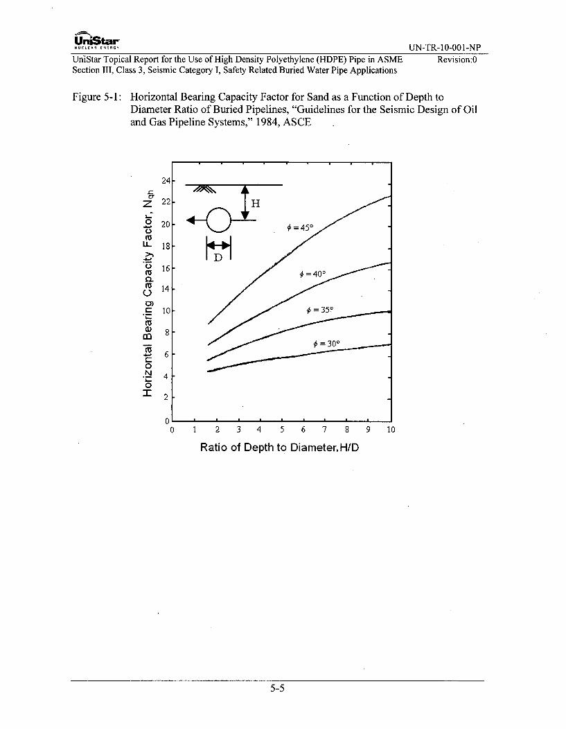
UrtiStar-NUCLEAR ENERGY UN-TR-10-001-NP
UniStar Topical Report for the Use of High Density Polyethylene (HDPE) Pipe in ASME Revision:0Section III, Class 3, Seismic Category I, Safety Related Buried Water Pipe Applications
Figure 5-1: Horizontal Bearing Capacity Factor for Sand as a Function of Depth toDiameter Ratio of Buried Pipelines, "Guidelines for the Seismic Design of Oil
and Gas Pipeline Systems," 1984, ASCE
z
L.:
a--
0
M
LL
0-
0)
M
--41)
0a
0N
"1-
0 1 2 3 4 5 6 7 8 9 10
Ratio of Depth to Diameter. H/D
5-5

UniStar-NUCLEAR ENERGY UN-TR-10-001-NP
UniStar Topical Report for the Use of High Density Polyethylene (HDPE) Pipe in ASME Revision:0Section III, Class 3, Seismic Category I, Safety Related Buried Water Pipe Applications
Figure 5-2: Horizontal Bearing Capacity Factors as a Function of Depth to Diameter Ratiofor Pipelines Buried in Sand (A) and Clay (B), "Guidelines for the SeismicDesign of Oil and Gas Pipeline Systems," 1984, ASCE
Nqh Nch
2 5 10 20 50 2 5 1002
4
6
H
D8
10
12
14
16
18
20(a)Granular Soil (b)Cohesive Soil
5-6

UniStarNUCLEAR ENERGY UN-TR- 10-001-NP
UniStar Topical Report for the Use of High Density Polyethylene (HDPE) Pipe in ASMESection III, Class 3, Seismic Category I, Safety Related Buried Water Pipe Applications
Revision:0
Figure 5-3: Vertical Bearing Capacity Factors vs. Soil Angle of Internal Friction for Sand,"Guidelines for the Seismic Design of Oil and Gas Pipeline Systems," 1984,ASCE
H
-1
C,
1=-4
400r
30
200
10
0-
060 50 40 30 20 10 0 20 40 60 80
Figure 5-4: Vertical Uplift Factor for Sand as a Function of Depth to Diameter Ratio ofBuried Pipelines, "Guidelines for the Seismic Design of Oil and Gas PipelineSystems," 1984, ASCE
12I I I I I . I I I I I
C
248
10 j+L81
6
41
.?
0a1 i f Dept0J 2 4
Ratio of Depthi
- | i | i i
6 8 1011to Diameter, HID
5-7

UniStar-NUCLEAR"R UN-TR-10-001-NP
UniStar Topical Report for the Use of High Density Polyethylene (HDPE) Pipe in ASME Revision:0Section III, Class 3, Seismic Category I, Safety Related Buried Water Pipe Applications
Figure 5-5: Vertical Uplift Factor for Clay as a Function of Depth, Do, Diameter Ratio ofBuried Pipelines, "Guidelines for the Seismic Design of Oil and Gas PipelineSystems," 1984, ASCE
16 -- _ +
• 12 Fully Bonded Anchor Plate
0
S 8•
. Immediate Breakaway ofAnchor Plate
C4
> 0
0 2 4 6 8Ratio of Depth to Diameter, I-D
Using the previous formulation, the modulus (psi) of subgrade reaction in a givendirection ki is given by the formulation for the transverse, vertical up, and verticaldown springs as shown in the following equation,
k, =f1/D
where,
fy = force, f, lbs, calculated using the formulations in Table 5-1.D = outer diameter of pipe, in.
When using this method, ki is the parameter E' in defining the ovaling stiffnessdiscussed in Section 5.4.2. The spring stiffness for the soil is given by the followingequation,
k=fx L/du
where,
fij,dij= force, f, and displacement, d, calculated using Table 5-1.kij = spring stiffness in a given direction calculated using the formulations
in Table 5-1.Li = The effective length of piping modeled by the discrete spring as shown
in Figure 5-6 and Figure 5-7.
The spring stiffness in the vertical direction is adequately modeled using an averageof the vertical up and down springs calculated using kij=fij xLi/dij. The springstiffness used for the combined soil/pipe ovaling behavior that should be modeled is
5-8

Unintar"..UC.....NE.R UN-TR-10-001-NP
UniStar Topical Report for the Use of High Density Polyethylene (HDPE) Pipe in ASME Revision:0Section III, Class 3, Seismic Category I, Safety Related Buried Water Pipe Applications
defined using springs in series equations. The axial spring is modeled usingkij=fij xLi/dij and does not require correction for ovaling.
Figure 5-6: Computer Modeling With Soil/Pipe Ovaling Springs
D Nominal Pipe DiameterLp Influence Length
5-9

UnStar'UN-TR- 10-001-NP
UniStar Topical Report for the Use of High Density Polyethylene (HDPE) Pipe in ASMESection III, Class 3, Seismic Category I, Safety Related Buried Water Pipe Applications
Revision:0
Figure 5-7: Modeling of Soil/Pipe Ovaling Springs At Changes in Direction Beyond theInfluence Length
2D1,20,
( a ) Branch Connection
L. 10D L. 213 ,z 2D j. 2D
I TTt- -- 4
I
IC4
0
N
( b ) Elbow
5.5 Vertical Piping Runs
For vertical piping there are no significant concerns with trench loading and surfaceloading creating a lateral crushing load on the piping. For these loadings, the lateralpiping runs preceding or following the vertical run will, in most cases, control thedesign of the buried piping system. Therefore, explicit consideration of the trenchand surface loading for vertical runs of buried piping is not required.
When using computer analysis for thermal and seismic loadings, vertical piping runsare considered essentially the same as horizontal piping runs in determination of theinfluenced length, however, for vertical piping, the soil spring stiffness is applied asfollows:
1. The transverse soil spring stiffness should be applied in each of the twoorthogonal directions.
2. The axial soil spring stiffness should be applied in the vertical direction.
In addition, the thermal expansion and axial strains shall also be applied to thevertical piping runs (in the axial direction). For vertical piping runs, the throughwall trench bending stress may be taken as zero.
5-10

UniStar-N.. CLE.F.NEA UN-TR-10-001-NP
UniStar Topical Report for the Use of High Density Polyethylene (HDPE) Pipe in ASME Revision:0Section III, Class 3, Seismic Category I, Safety Related Buried Water Pipe Applications
6.0 PIPE SUPPORT DESIGN CRITERIA
6.1 General
The HDPE piping will be buried in the ground and supported by the soil. Once thepipe is buried underground, the weight of the soil covering the pipe will restrain thepiping against the effects of buoyancy forces due to ground water. Piping shall beplaced in the ground and buried in such a manner as to prevent damage to the piping.
6.2 Temporary Supports for Inspection
The buried pipe will require a visual inspection of the fused joints and shall besupported by the engineered back fill in a manner that will hold the pipe in placeduring testing while still leaving the joint accessible for examination.
6.3 Building Anchor Movements
The only mechanical pipe support in the HDPE piping systems will be the anchor atthe building penetration where the metallic pipe exits the building. These supportswill be designed to ASME Section III, Division 1, subsection NF. The movementsdue to building expansion/settlement as well as seismic anchor movements shall beanalyzed. Movements less than 1/16" are not required for the piping analysis.
6-1

UniStar-NUCLEAR ENRGY UN-TR- 10-001-NP
UniStar Topical Report for the Use of High Density Polyethylene (HDPE) Pipe in ASME Revision:0Section III, Class 3, Seismic Category I, Safety Related Buried Water Pipe Applications
7.0 INSTALLATION REQUIREMENTS
7.1 General Requirements
7.1.1 Scope
Methods of fabrication and installation is by straight HDPE pipe, butt fusion joints,two segment, three segment and five segment mitered elbows (made from HDPEpipe), and HDPE to metallic flanges. Use of threaded or adhesive joints with PEmaterial is not permitted.. Metallic interface items will be installed following therequirements of ASME Section III, Subsection ND.
7.1.2 Examinations
Examinations are performed by QA/QC personnel. These visual examinations arerequired to be performed by personnel and procedures qualified to the requirementsdelineated in Sections 8.2.1 and 8.4, respectively.
7.1.3 Repair of Material
HDPE pipe originally accepted on delivery in which defects not exceeding the limitsin Section 10.4.1 are discovered may be used if the pipe is repaired per Section8.1.1 .B or the defective area is physically removed.
7.1.4 Material Identification
A. Material for pressure retaining parts will carry identification markings which willremain distinguishable until the component is assembled or installed. If theoriginal markings are cut off or the material is divided, the same marks will betransferred to the cut parts or a coded marking will be used to assure theidentification of the material during subsequent installation. An as-built sketchor a tabulation of materials will be made identifying each piece of material with aCertificate of Analysis or Certified PE Test Report, where applicable, and thecode marking.
B. Material from which the identification marking is lost or not legible fortraceability is treated as non-conforming material until verifications are madeand documented to assure material identification. Testing is required unlesspositive identification can be made by other documented evidence. The materialshall then be marked in accordance with the requirements of Section 10.3.1 torestore proper identification.
7.2 Cutting and Bending
7.2.1 Cutting
Materials may be cut to shape and size by mechanical means such as machining orcutting.
7.2.2 Bending
The following requirements shall apply to the forming and bending processes used inthe fabrication and erection of Polyethylene pipe:
7-1
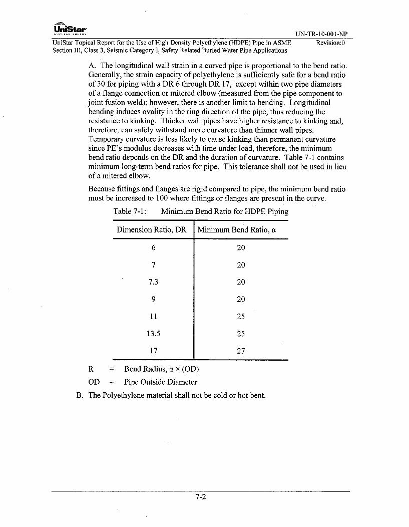
U'niStar".N.....A..... UN-TR- 10-001-NP
UniStar Topical Report for the Use of High Density Polyethylene (HDPE) Pipe in ASME Revision:0Section III, Class 3, Seismic Category I, Safety Related Buried Water Pipe Applications
A. The longitudinal wall strain in a curved pipe is proportional to the bend ratio.Generally, the strain capacity of polyethylene is sufficiently safe for a bend ratioof 30 for piping with a DR 6 through DR 17, except within two pipe diametersof a flange connection or mitered elbow (measured from the pipe component tojoint fusion weld); however, there is another limit to bending. Longitudinalbending induces ovality in the ring direction of the pipe, thus reducing theresistance to kinking. Thicker wall pipes have higher resistance to kinking and,therefore, can safely withstand more curvature than thinner wall pipes.Temporary curvature is less likely to cause kinking than permanent curvaturesince PE's modulus decreases with time under load, therefore, the minimumbend ratio depends on the DR and the duration of curvature. Table 7-1 containsminimum long-term bend ratios for pipe. This tolerance shall not be used in lieuof a mitered elbow.
Because fittings and flanges are rigid compared to pipe, the minimum bend ratiomust be increased to 100 where fittings or flanges are present in the curve.
Table 7-1: Minimum Bend Ratio for HDPE Piping
Dimension Ratio, DR Minimum Bend Ratio, a
6 20
7 20
7.3 20
9 20
11 25
13.5 25
17 27
R = Bend Radius, a x (OD)
OD = Pipe Outside Diameter
B. The Polyethylene material shall not be cold or hot bent.
7-2
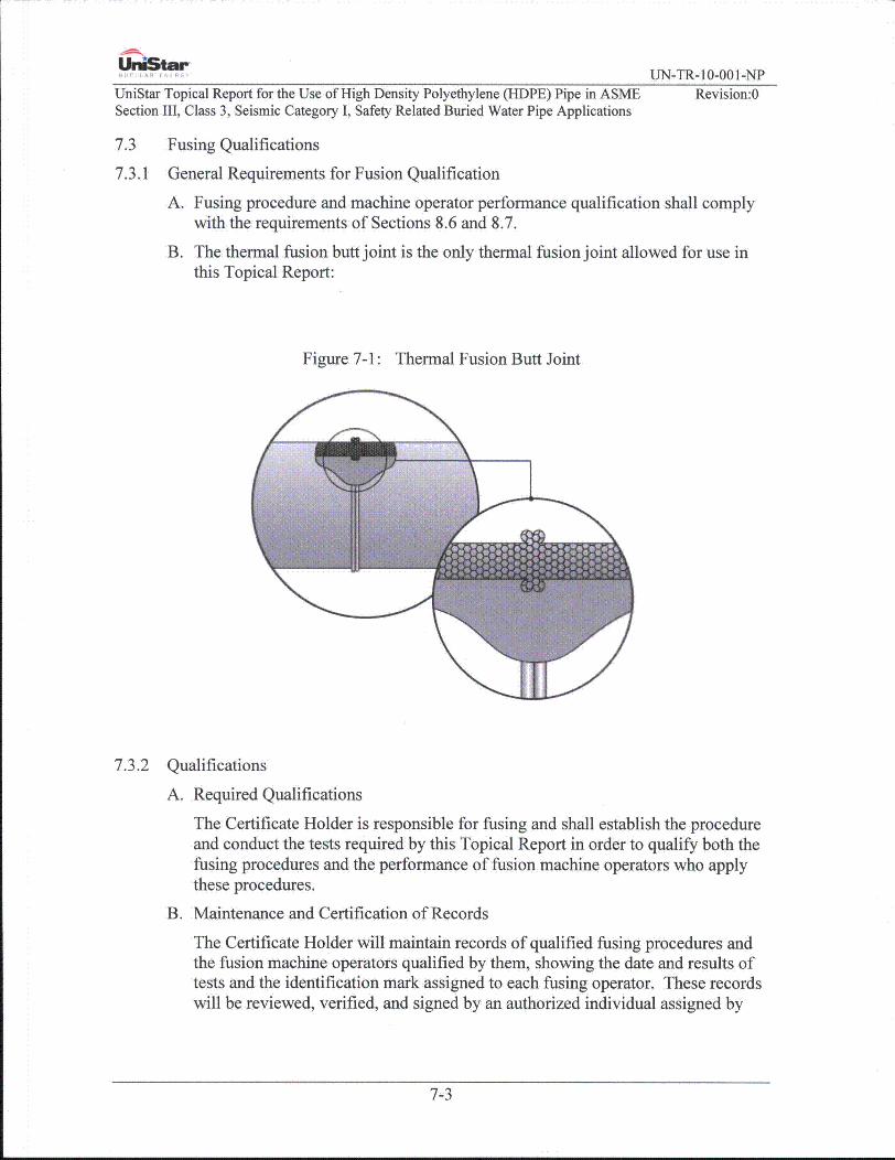
UnistarUN-TR-10-001-NP
UniStar Topical Report for the Use of High Density Polyethylene (HDPE) Pipe in ASMESection III, Class 3, Seismic Category I, Safety Related Buried Water Pipe Applications
Revision:0
7.3 Fusing Qualifications
7.3.1 General Requirements for Fusion Qualification
A. Fusing procedure and machine operator performance qualification shall complywith the requirements of Sections 8.6 and 8.7.
B. The thermal fusion butt joint is the only thermal fusion joint allowed for use inthis Topical Report:
Figure 7-1: Thermal Fusion Butt Joint
7.3.2 Qualifications
A. Required Qualifications
The Certificate Holder is responsible for fusing and shall establish the procedureand conduct the tests required by this Topical Report in order to qualify both thefusing procedures and the performance of fusion machine operators who applythese procedures.
B. Maintenance and Certification of Records
The Certificate Holder will maintain records of qualified fusing procedures andthe fusion machine operators qualified by them, showing the date and results oftests and the identification mark assigned to each fusing operator. These recordswill be reviewed, verified, and signed by an authorized individual assigned by
7-3

UniStar-NUCLEAR ENERGY UN-TR-10-001-NP
UniStar Topical Report for the Use of High Density Polyethylene (HDPE) Pipe in ASME Revision:0Section III, Class 3, Seismic Category I, Safety Related Buried Water Pipe Applications
the Certificate Holder and they will be accessible to the Authorized Nuclear
Inspector.
C. Fusing Prior to Qualification
Fusing will not be undertaken until after the Fusion Procedure Specification(FPS) is qualified. Only fusion operators who are qualified in accordance withSections 7.3, 8.6 and 8.7 of this Topical Report shall be used.
D. Transferring Qualifications
The FPS qualifications and performance qualification tests for fusion machineoperators conducted by one Certificate Holder are not transferable to anotherCertificate Holder.
7.3.3 Requirements for Fusing Procedure Qualifications Tests
A. Conformance to Sections 8.6 and 8.7 Requirements
Fusing procedure qualification tests shall be in accordance with the requirementsof Sections 8.6 and 8.7.
B. Preparations of Test Coupons and Specimens
Removal of test coupons from the fusion test coupon and the dimensions ofspecimens made from them shall conform to the requirements of Sections 8.6and 8.7.
7.4 Rules Governing Making Fused Joints
7.4.1 General Requirements for Making Fused Joints
A. Identification, Storage, and Handling of PE Materials
The Certificate Holder is responsible for control of PE materials that are used inthe fabrication and installation of components. Suitable identification, storage,and handling of PE material will be maintained.
B. Cleanliness and Protection of Surfaces to be Fused
The fusing surfaces will be fiee of scale, rust, oil, grease, and other deleteriousmaterial. The work will be protected from deleterious contamination and fromrain, snow, and wind during fusing operations. Fusing will not be performed onwet surfaces.
7.4.2 Rules for Making Fused Joints
A. Fused Joint Fit-up Requirements
1) Components of different outside diameters will not be fused together.
2) The alignment of components for open butt fusion joints will be held inposition by the fusing machine. The outside diameters of piping componentsto be fused will be aligned as accurately as practical within existingcommercial tolerances on diameters, wall thicknesses, and out of roundness.
7-4

UniStar-NUCLEAR ENERGY UN-TR- 10-001-NP
UniStar Topical Report for the Use of High Density Polyethylene (HDPE) Pipe in ASME Revision:0Section III, Class 3, Seismic Category I, Safety Related Buried Water Pipe Applications
Alignment will be preserved during fusion. The external misalignment of theends to be joined will not exceed 1/16".
3) To fuse components with differing DR's, the component with the smaller DRwill be machined and tapered to meet the wall thickness of the componentwith the larger DR and shall comply with Figure 7-2, External Pipe WallTransition Taper.
Figure 7-2: External Pipe Wall Transition Taper
tn = nominal thickness of thinner componentCmin = 2.5 tn (c values are after facing)
Taper Slope:
rl'min = 0.05tn
L (bac)]< 0.60 and, Kac] in> 0.30
r2'min = 0.05tn
B. Identification of Joints by Fusing Operator
Each fusing operator will apply the identification mark assigned to him by theCertificate Holder adjacent to all permanent fused joints or series of joints onwhich he fuses. The marking will be I ft or less from the fusion bead and will bedone with permanent metallic paint marker or stenciling marker.
External and internal fusion beads are not part of the pressure boundary and canbe removed at any time.
7-5

UniStar-NEENERGY UN-TR- 10-001-NP
UniStar Topical Report for the Use of High Density Polyethylene (HDPE) Pipe in ASME Revision:0Section III, Class 3, Seismic Category I, Safety Related Buried Water Pipe Applications
C. Minimum Ambient Temperature
Fusion is performed with a minimum ambient temperature of 50'F. If theambient temperature is not suitable for fusion (<50'F), a tent will be erectedaround the fusion joint being made to control the climate around the joint.
D. Repairs
Repair of a fused joint is not allowed. Unacceptable joints are cut out andreplaced.
7.4.3 Fusion Data Acquisition Recorder
The fusion machine shall have a data acquisition recorder attached to it. The dataacquisition record produced by the device shall include important information of thefusion process as show in Section 8.6.1 to record essential variables of the fusionprocess.
A. Failure to run the recorder during the fusion process shall cause rejection of thefusion joint.
B. The data acquisition records shall be compared to the FPS to ensure that therequirements of the FPS were met. If any FPS requirements, not limited to theessential variables is out of the approved range, the fuse joint shall be cut out andremade.
7.5 Fabrication and Assembly
7.5.1 General Assembly Requirements
Alignment of joints for assembly could result in piping distortion greater than therequirements of Section 7.2.2. This may result in the introduction of a permanentstrain in the piping components and is prohibited.
7.5.2 Flanged Joint Using HDPE Material to Steel Flanged Joints
All connections of PE to steel piping will be made using a PE to steel flanged joint.See Figure 7-3 for a typical PE to metal flange configuration. For a uniformhydraulic design, the HDPE pipe is sized to approximately match the steel pipe's ID.When the PE pipe OD is one or more pipe sizes larger than the steel pipe, a steelreducing flange will be used to match the sealing surface face area of the PE flangeadapter (not shown in Figure 7-3).
A. The PE flange connection will be constructed using a PE flange adapter having aDR or SDR equal to or less than that of the attached PE pipe.
B. The PE flange adapter will be connected to the steel mating flange using a steelbacking ring. The backing ring will have a design pressure rating equal to orgreater than the metal flange. The pressure rating and design of the steel flangewill meet the requirements of ASME Section III, ND-3647.
7-6

UniStarNUCLEAR.E.ERY UN-TR-10-001-NPUniStar Topical Report for the Use of High Density Polyethylene (HDPE) Pipe in ASME Revision:0Section III, Class 3, Seismic Category I, Safety Related Buried Water Pipe Applications
C. Before bolting up, flange faces shall be aligned to the design plane within 1/16"inch. If measured across any diameter; flange bolt holes shall be aligned within1/8" inch maximum offset.
D. The flanges are joined using bolts of a size and strength that conforms to therequirements of ASME Section III and ASME B 16.5 or B 16.47 as applicable.Bolts or studs shall extend completely through the associated nuts. Hardened flatwashers are used under bolt heads and nuts.
E. The use of a gasket is optional for smaller pipe sizes, but is required when steelreducing flanges are used. If used, no more than one gasket is used betweencontact faces in assembling a flanged joint.
F. The flange bolts are tightened to the minimum torque values required for sealingagainst the maximum sustained internal pressure and transient surge pressuresspecified in Section 3.10.4. Criteria in PPI TN-38 will be used to establish therequired bolt torque.
Figure 7-3: Transition Flange Arrangement
Washers Metallic backing ring
Metallic flange Bolting
Pflange adapterMetallic pipe F - n joint
Gasket--_- _- -- - - --- - -- - --- - -- -pipe
Metallic piping 1i o Pr piping
7.6 Excavation and Backfill
7.6.1 Excavation and backfill will be in accordance with codes and standards referenced inSection 2.0, as applicable, including ASTM F1668 and ASTM D2774. Trenchesshall be near vertical where possible. These Codes and Standards identify minimumstandards required for backfill. Site specific structural fill requirements may beinstituted if demonstrated to be more stringent than the basic requirements.
7.6.2 Unless shown otherwise on drawings, depth of cover over pipes shall be a minimumof 3 feet from the top of pipe to finished grade.
7.6.3 Trenches will be kept free of water during construction by use of dewateringequipment. When trench bottom is reached, any unusual conditions shall be
7-7

UniStar-NUCLEAR..NERGY UN-TR-10-001-NP
UniStar Topical Report for the Use of High Density Polyethylene (HDPE) Pipe in ASME Revision:0Section III, Class 3, Seismic Category I, Safety Related Buried Water Pipe Applications
evaluated prior to proceeding with the setting of pipe. Trenches shall be excavatedto the required depth to ensure uniform bearing of the bedding.
7.6.4 Pipe fittings and accessories are carefully inspected for defects before installation.Defective, unsound or damaged materials will be rejected and replaced.
7.6.5 No shims or lumps of soil will be used to adjust the pipe to grade.
7.6.6 Pipe will be bedded in compacted granular material placed on a flat trench bottom.The granular material shall be crushed stone, sand or pea gravel which shall pass a1/2" sieve, but shall be retained by a No. 4 sieve. The granular material beddingshall have a minimum thickness of one-fourth the pipe diameter and shall extendhalfway up the pipe barrel at the sides.
7.6.7 The remainder of the side fills and a minimum depth of 12" over the top of the pipeshall be filled with carefully compacted material. Backfill will be well tamped inlayers not more than 6" deep under and around pipes to, as a minimum, a 90%standard proctor per ASTM D698 to prevent settlement or lateral movement, andshall contain no ashes, cinders, refuse or other corrosive material. Rock shall not beplaced in trenches. Backfill under roads and structures shall meet, as a minimum,95% proctor per ASTM D1557.
7.6.8 Partial backfilling between pipe joints will be required to prevent pipe movementduring the hydro test.
7.6.9 Pipe bedding and cover materials will be monitored by an inspector using fieldmoisture-density tests. Field results will be compared to laboratory moisture-densitytests to ensure that the required compaction density is attained and that the materialis being placed with proper moisture. Proper compaction is necessary to verify soildesign properties are met. Laboratory moisture-density tests will be performed oneach material to be used as fill. Fill will be characterized by material gradation ofon-site material or from qualified off-site borrow areas. Frequency of tests will bespecified. Unique site soil conditions may require different bedding and backfill.
7.6.10 The precautions necessary to protect the HDPE pipe from damage will conform tothe requirements listed in ASTM D2774 and ASTM F 1668.
7-8
UniStar-.UCLEAR ENERGY UN-TR- 10-001-NP
UniStar Topical Report for the Use of High Density Polyethylene (HDPE) Pipe in ASME Revision:0Section III, Class 3, Seismic Category 1, Safety Related Buried Water Pipe Applications
8.0 INSPECTIONS AND TESTS
8.1 Materials
8.1.1 Examination of Materials
A. Receipt Examination
1) PE material external surfaces shall be given a visual examination prior toinstallation. Any indentation that does not meet the requirements of Section10.4.1 shall be unacceptable.
2) Personnel performing the examination are qualified in accordance with theCodes and Standards referenced in Section 8.4.
B. Repair of PE Material
The Non Conformance Reporting (NCR) process will be used to document asfound conditions and repair of HDPE pipe.
Pipe surface gouges or cuts that are less in depth than the defect described inSection 10.4.1 and do not interfere with the minimum required wall thickness,may be removed by grinding or machining in accordance with the followingrequirements.
The repaired pipe may be used as-is provided:
1. The removed area has a minimum taper of 3:1 without sharp edges (width:height), and,
2. The remaining wall thickness is in excess of tdesign required by this TopicalReport.
If the damaged area is in the flange face, the entire flange can be removed or theface can be refaced.
8.1.2 PE Material Fusing Qualification Testing
See Section 10.3.4.
8.2 Examination Procedures
8.2.1 General Examination Requirements
A. Visual examinations are conducted in accordance with the examination methodof the 2001 Edition through 2003 Addenda of the ASME BPVC Section V,Article 9.
B. Ultrasonic examinations are conducted in accordance with the requirements ofthe 2001 Edition through 2003 Edition of the ASME BPVC Section V, Article 4.
C. Personnel qualified to perform visual examinations on HDPE pipe installation,excluding the hydrostatic pressure test, will receive the same training as requiredfor the fusion machine operator in Sections 8.6 and 8.7. Training will be
8-1

UniStar'NUCLEAR ENERGY UN-TR-10-001-NP
UniStar Topical Report for the Use of High Density Polyethylene (HDPE) Pipe in ASME Revision:0Section III, Class 3, Seismic Category I, Safety Related Buried Water Pipe Applications
documented on a training record. See Section 8.4 for personnel qualificationrequirements.
Personnel performing visual examinations required by Sections 8.2.4.D and8.2.4.E will be qualified and certified as a VT-1 in accordance with IWA-2000 ofASME Section XI.
Personnel performing visual examinations required by Section 8.2.4.F will bequalified and certified as a VT-2 in accordance with IWA-2000 of ASMESection XI and receive four hours of training in PE piping and joining practices.
D. Records pertaining to procedure and personnel qualifications and examinationsof materials and joints will be retained in accordance with the Certificate Holderand/or Owner's Quality Assurance Program.
8.2.2 Required Examinations
The following visual examination and inspections shall be conducted:
A. Inspection of the general surface for indentations.
B. Fusion joints, including review and verification of fusion data for the joint
C. All fusion joints during the hydrostatic test (Section 8.5). For any fusion jointstested during the hydrostatic test, any fusion joint leakage shall cause rejection ofthe joint.
1) The visual examination shall be conducted by examining the accessibleexternal exposed surfaces of pressure retaining components for evidence ofleakage.
2) For components whose external surfaces are inaccessible for direct visualexamination, only the examination of the surrounding area (including areasor surfaces located underneath the components) for evidence of leakage shallbe required.
3) Flange leakage is excluded from this requirement.
8.2.3 Examination Procedures
A. Examinations performed are executed in accordance with detailed writtenprocedures which have been proven by actual demonstration to the satisfaction ofthe Authorized Nuclear Inspector. Written procedures, records of demonstrationof procedure capability, and personnel qualification are available to theAuthorized Nuclear Inspector.
B. The nondestructive examination procedures are qualified using performancebased demonstrations to assure that the examination process satisfactorilyidentifies rejectable conditions predicted on the acceptance criteria definedherein. The qualification demonstration will address material, configuration,pipe and fitting sizes and environmental conditions. The performance baseddemonstration is conducted and documented in accordance with the ASMEBPVC Section V, Article 14.
8-2

UniStarN.. U EARE RGUN-TR- 10-001-NP
UniStar Topical Report for the Use of High Density Polyethylene (HDPE) Pipe in ASME Revision:0Section III, Class 3, Seismic Category I, Safety Related Buried Water Pipe Applications
8.2.4 Visual Examination of Completed Fused Joints
Visual examination of all fused joints are conducted:
A. Upon the completion of the cooling period
B. After the review required by Section 7.4.3 has been reviewed and accepted
C. Before piping is placed in the burial trench
D. During receipt inspection of the external surface for indentations, nicks, gouges,etc.
E. On fusion joints after the fusion process including a review and verification offusion data for the joint and external surfaces. The examination evaluates theadjacent base material for at least two inches on either side of the joint.
F. On pipe fusion joints during the hydrostatic test.
8.2.5 Time of Flight Diffraction (TOFD)
To provide added assurance of joint integrity, an ultrasonic Time of FlightDiffraction examination is performed for all completed fused joints.
A. The provider of this examination must adhere to 1OCFR50 Appendix B Programrequirements.
B. A demonstration will be performed that verifies the Time of Flight Diffractionprocedure applies available technology for this technique. The demonstrationsshall include specimens containing 10 flaws of varying shapes and sizes tosimulate flaws expected to occur in unacceptable joints.
C. Acceptance criteria will be evaluated and will be based on industry standards.Current acceptance criteria requires that any un-bonded area in a joint is causefor rejection.
D. Time of Flight Diffraction examination records are retained as permanentrecords.
E. Ultrasonic Examination of Completed Fused Joints (Time of Flight)
Ultrasonic examination of all fused joints will be conducted:
1) Upon the completion of the cooling period,
2) After the review required by Section 7.4.3 has been reviewed and accepted,
3) Before piping is placed in the burial trench,
4) Shall evaluate the adjacent base material for at least two inches on either sideof the joint.
8-3

U'niStar-- - E- - UN-TR-10-001-NP
UniStar Topical Report for the Use of High Density Polyethylene (HDPE) Pipe in ASME Revision:0Section III, Class 3, Seismic Category I, Safety Related Buried Water Pipe Applications
8.3 Acceptance Standards
Unacceptable joints are removed. Repair of unacceptable joints is not permitted.
8.3.1 Visual Examinations Acceptance Criteria of External Surfaces
Thermal Fusion Butt Joints shall meet the following:
A. Joints shall exhibit proper fusion bead configuration, (see Figure 8-2, FusionBead Configuration)
B. There shall be no evidence of cracks or incomplete fusion,
C. Joints shall not be visually angled or offset. The ovality offset shall be less than10% of the minimum wall thickness of the fused components,
D. The cleavage between fusion beads shall not extend to or below the outsidediameter pipe surface (see Figure 8-1, PE Pipe (Cross Section View)).
Figure 8-1: PE Pipe (Cross Section View)
t -(a) Visually Acceptable (b) Visually Acceptable(Uniform bead around pipe) (Nonuniform bead
around pipe)
Cleavage tip shall notmeet or extendbelow pipe surface'
(c) Visually Acceptable (d) Visually Unacceptable(Nonuniform bead around (Nonuniform/uniform bead,pipe localized diameter around pipe - V-Groovemismatch less than 10% too deep at pipe-tangent)of the wall)
8-4

UN-TR- 10-001-NPUniStar Topical Report for the Use of High Density Polyethylene (HDPE) Pipe in ASMESection III, Class 3, Seismic Category I, Safety Related Buried Water Pipe Applications
Revision:0
Figure 8-2: Fusion Bead Configuration
(a) Butt Fusion of Pipe(Unacceptable appearance-insufficient melt)
(b) Butt Fusion of Pipe(Unacceptable appearance-inadequate roll back)
ic) Butt Fusion of Pipe (dM Butt Fusion of Pipe(Unacceptable appearance-improper alignment) (Unacceptable appearance)
(s) Butt Fusion of Pipe(Unacceptable appearance-incomplete face off)
If) Butt Fusion of Pipe(Unacceptable appearance-incomplete face off)
Note: This is only to be used as a guide.
8-5
UniStar"NUCLEAR ENERGY UN-TR- 10-001-NP
UniStar Topical Report for the Use of High Density Polyethylene (HDPE) Pipe in ASME Revision:0Section III, Class 3, Seismic Category I, Safety Related Buried Water Pipe Applications
8.3.2 Process Verification
The data acquisition record for each joint is reviewed and compared to the FusionProcedure Specification (FPS) to ensure the proper parameters and procedures werefollowed in making the fused joint.
8.4 Qualification of Non-Destructive Examination Personnel
8.4.1 General NDE Qualification Requirements
Individuals performing Code required nondestructive examinations and/or evaluatingthe results will be qualified in accordance with ASME Section III, ND-5520 orASME Section XI, Division 1, IWA-2300 as applicable.
Personnel performing visual and ultrasonic inspections will demonstrate theirproficiency by performing an examination of physical samples of acceptable andunacceptable HDPE pipe fusion joints. A minimum of five flaw samples will beused for the visual examination procedure. In order to be considered qualified,personnel must identify at least 90% of the known defects in the test coupon.
8.4.2 Certificate Holder Requirements
A. Personnel performing visual and ultrasonic examinations are qualified inaccordance with ASME Section III, ND-5520 and the Certificate Holder's NDEProgram. This training is documented on a training record.
B. Personnel performing nondestructive examinations on material receipt andcompleted fused joints shall receive the required training in Section 8.2.1 .C.Personnel performing only the hydrostatic test visual examination are notrequired to complete the training in Section 8.2.1 .C, but are required to completefour hours of training in PE piping and joining practices. Training isdocumented on a training record.
8.4.3 Owner Requirements
A. Personnel who will be qualified to perform visual and ultrasonic examinationsand data acquisition record review on HDPE piping, excluding the hydrostaticpressure test, will receive the same training as required in Sections 8.6 and 8.7.This includes the use of a fusion machine to make a simple fused joint; the fusedjoint is not required to be tested. Training is documented on a training record.
B. In addition to training required by the paragraph above, personnel performingvisual examinations shall receive an additional 16 hours of training in HDPEpiping and joining practices, documented on a training record.
8-6

UniStarNUCLEA.ENERGY UN-TR- 10-001-NP
UniStar Topical Report for the Use of High Density Polyethylene (HDPE) Pipe in ASME Revision:0Section III, Class 3, Seismic Category I, Safety Related Buried Water Pipe Applications
8.5 Testing
8.5.1 General Requirements
A. Prior to initial operation, the installed system is hydrostatically tested in thepresence of the Authorized Nuclear Inspector in accordance with the proceduresand requirements of ASTM Standard F 2164.
B. All joints, including fused joints are left exposed for examination during the test.For long sections of piping, the hydrostatic testing may be accomplished bytesting in small subsections of the longer section. Upon a satisfactory test ofeach small section the piping may be buried. This process shall be documentedin the Certificate Holder's Quality Assurance Program or the Owner's QualityAssurance Program and found acceptable to the Authorized Nuclear InspectionAgency. The subsequent joint must be exposed for hydro testing uponcompletion of the fused joint.
C. The pressure in the test section shall be gradually (minimum rate of 5 psi/min notto exceed a maximum rate of 20psi/min) increased to the test pressure specifiedin 8.5.2.B below and held for four hours. Makeup water may be added tomaintain test pressure during this time to allow for initial expansion. Followingthe four hour initial pressurization period, the test pressure shall be reduced to1.5 times the Design Pressure and the system monitored for another one hour.Make up water may no longer be added to maintain pressure. Each joint shall beexamined. The pass/fail hydro test acceptance criteria is described in ASTMF2164 Paragraph 9.8 (e.g., if no visual leakage is observed and the pressureremains within 5% of the test pressure for the one hour, the pipe section undertest is considered acceptable).
D. The temperature of the piping under test will be maintained within thetemperature limits of the system design.
E. The total test time including initial pressurization, initial expansion, and time attest pressure, must not exceed eight hours. If the pressure test is not completedthe test section will be depressurized. The test section shall not be re-pressurizedfor at least eight hours.
F. A pneumatic test is not permitted.
8.5.2 Certificate Holder Hydrostatic Test Requirements
A. The piping system will be tested by hydrostatic test in accordance with ASMESection III, ND-6200.
B. The minimum test pressure shall be 1.5 times the Design Pressure of the PEpiping system plus 1 Opsig. The maximum test pressure shall be 1.5 times theDesign Pressure of the PE piping system plus 20psig.
C. The test shall be conducted and documented by qualified personnel inaccordance with the Certificate Holder's ASME QA Program.
8-7

UniStar"NUCLEAR ENERGY UN-TR-10-001-NP
UniStar Topical Report for the Use of High Density Polyethylene (HDPE) Pipe in ASME Revision:0Section III, Class 3, Seismic Category I, Safety Related Buried Water Pipe Applications
8.6 Fusion General Requirements
The requirements in this Section apply to the preparation of the FPS and thequalification of fusion machine operators for thermal butt fusion. The minimumrecommended training guidelines for fusion machine operators is provided in PPITN-42/September 2009.Some of the more common terms related to fusion are defined in Section 1.1 and
ASTM F412-06, Standard Terminology Relating to Plastic Piping Systems.
A. Responsibility
1) Fusion
Each manufacturer or contractor is responsible for the fusing done by theirorganization. Tests shall be conducted to qualify the procedures used in theproduction of the fused joints made and the performance of fusion machineoperators who use these procedures (Section 8.8).
2) Records
Each manufacturer or contractor shall maintain a record of the resultsobtained in the fusing procedure and fusion machine operator performancequalifications. These records shall be certified by the manufacturer orcontractor and shall be accessible to the Authorized Nuclear Inspector.
3) Documents
A FPS is a written document that provides direction to the fusion machineoperator for making fused joints. Any manufacturer or contractor that willhave responsible operational control of production fusing shall have a FPSthat has been qualified by that manufacturer or contractor in accordance withSection 8.7.
" The FPS specifies the conditions under which the fusing must beperformed. These conditions include the HDPE materials that arepermitted. Such conditions are referred to as the fusing "essentialvariables." When a FPS is to be prepared by the manufacturer orcontractor, it shall address these essential variables.
" The purpose for the qualification of a FPS is to determine that thefused joint proposed for construction is capable of providing therequired properties for its intended application. FPS qualificationestablishes the properties of the fused joint, not the skill of the fusionmachine operator.
8-8

UniStar"NUCLEAR NERGY UN-TR-10-001-NP
UniStar Topical Report for the Use of High Density Polyethylene (HDPE) Pipe in ASME Revision:0Section III, Class 3, Seismic Category I, Safety Related Buried Water Pipe Applications
4) In performance qualification, the basic criterion established for fusionmachine operator qualification is to determine the operator's ability to operatethe fusing equipment to produce a sound fused joint.
B. Joint Orientation
The orientation of all fused butt joints produced for tests or production shall bemade within +/- 45 degrees of the horizontal axis position illustrated in Figure8-3.
Figure 8-3: Horizontal Axis Position
C. Training
Each fusion machine operator will receive a minimum of 24 hours of training,covering the principles of the fusion process and the operation of the fusionequipment. There will be a two part test at the end of this training; Part 1Theoretical Knowledge and Part 2 Performance Qualification.
" The theoretical test shall cover as a minimum: safety, fundamentals of thefusing process, and recognition of typical joint imperfections.
" The Performance Qualification test is performed using an approved FPS.
8.6.1 The Fusion Procedure is qualified at the extreme range of essential variables. Anychange in essential variables beyond the range for which it's qualified will requirere-qualification.
A. Data Acquisition Record Evaluation
1) Data Acquisition Recorder
The data acquisition recorder will be capable of recording the following buttfusion essential variables on each joint:
(1) Equipment model number(2) Pipe diameter(3) Pipe wall thickness(4) HDPE material type(5) Fusion cycle times(6) Fusion process temperature(7) Heater surface temperature immediately prior to insertion of the
heater plate
8-9

UniStarNUCLEAR ENERGY UN-TR- 10-001-NP
UniStar Topical Report for the Use of High Density Polyethylene (HDPE) Pipe in ASME Revision:0Section III, Class 3, Seismic Category I, Safety Related Buried Water Pipe Applications
(8) External environment temperature(9) Interfacial gauge pressure during the heating cycle(10) Interfacial gauge pressure during the fusion/cool cycle(11) The amount of time during the heat cycle(12) The amount of time to open the fusion machine, remove the heater,
and bring the pipe ends together at butt fusion pressure.(13) Amount of time during the fusion and cool cycle
Job information related to the joints such as job number, joint number,employee number, time, date, fusion machine identification, pipemanufacturer, interfacial pressure, drag pressure, and pipe material will alsobe documented.
The data acquisition recorder must be capable of storing at least one daysworth of butt fusion joint information and capable of downloading theinformation as a permanent record.
2) Data Acquisition Log Evaluation
The butt fusion joint record will be compared to the FPS to ensure that theproper butt fusion parameters and procedures were followed. If they werenot, the joint shall be cut and a new joint fused using the correct parametersand procedures per the FPS. An example of a Data Acquisition Log review isprovided in Section 8.10.
" Verify that all job related data was entered in the record.
" Verify that the recorded "Fuse" interfacial pressure was within therange of qualification.
" Verify that the heater surface temperature recorded was within therange of qualification.
" The examiner shall calculate the fusion pressure for the fusionmachine and add the drag pressure to confirm the machine'shydraulic fusion gauge pressure. This fusion gauge pressure mustbe shown in the recorded pressure/time diagram at the initialheater contact and during the fusion/cool cycle.
" Verify that the fusion gauge pressure dropped quickly to a valueless than or equal to the drag pressure at the beginning of the heatsoak cycle.
" At the end of the heat soak cycle, review that the machine wasopened, the heater removed and the pipe ends brought together atthe fusion gauge pressure as quickly as possible (not to exceedallowance in procedure).
Verify that the machine fusion gauge pressure was within the range ofqualification for the pipe diameter being fused. Observe that the datarecording device stopped logging at the end of the fusion/cool cycle.
8-10

.U......N ERGY UN-TR-10-001-NP
UniStar Topical Report for the Use of High Density Polyethylene (HDPE) Pipe in ASME Revision:0Section III, Class 3, Seismic Category I, Safety Related Buried Water Pipe Applications
8.6.2 Types of Mechanical Tests Required for Qualification
A. High Speed Tensile Impact Test
1) Significance and Use
This test method is designed to impart tensile impact energy to a butt fusedplastic pipe specimen. The failure mode is used as criterion in the evaluationof the butt fusion joint.
2) Test Specimens
The test specimen shall conform to the dimensions shown in Figure 8-4. Testspecimens of butt fused pipe shall have the bead remain on the outside andinside. Test specimens of butt fused pipe shall use the full wall thickness.
Test specimens shall be prepared by machining operations on butt fusedsections of pipe and on the pipe itself. The machining operations shall resultin a smooth surface on both sides of the reduced area with no notches orgouges.
All surfaces of the specimen shall be free of visible flaws, scratches, orimperfections. Marks left by coarse machining operations shall be carefullyremoved with a fine file or abrasive, and the filed surfaces shall then besmoothed with abrasive paper (600 grit or finer). The finishing sandingstrokes shall be made in a direction parallel to the longitudinal axis of the testspecimen. In machining a specimen, undercuts that would exceed thedimensional tolerances shall be avoided.
When marking the specimens, use a permanent marker of a color that will beeasily read or etch the specimen number in the area outside the hole.
8-11
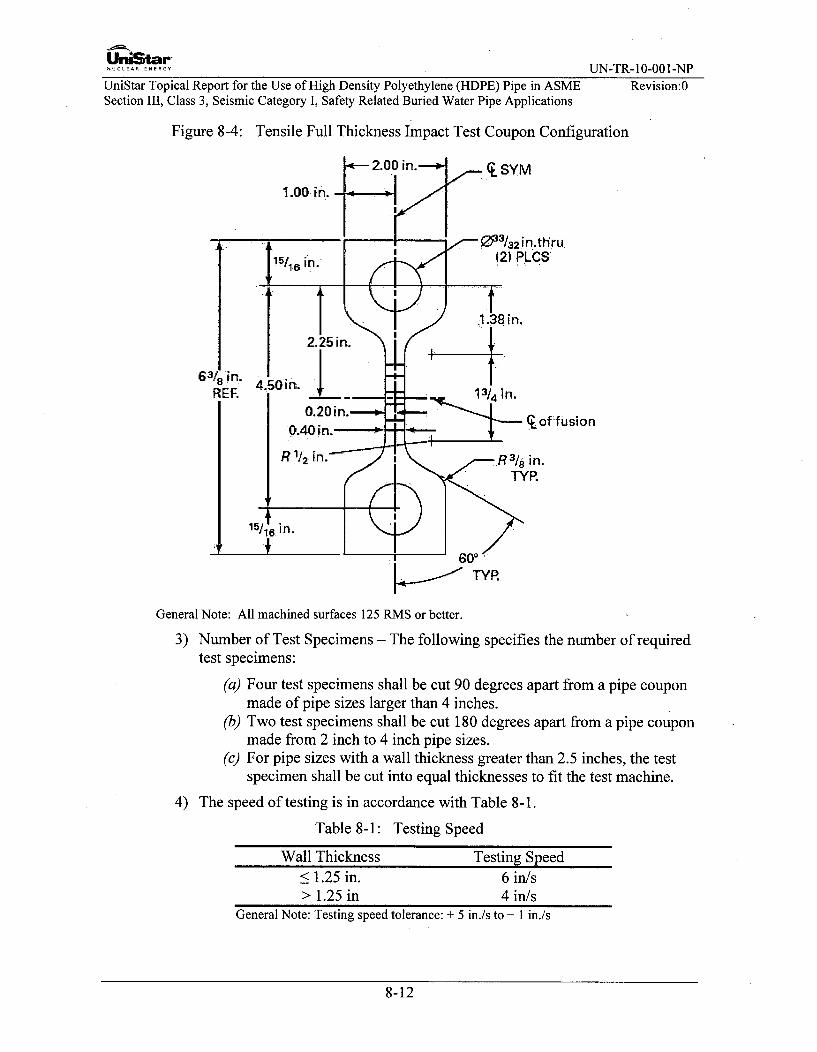
UnULArG UN-TR-10-001-NP
UniStar Topical Report for the Use of High Density Polyethylene (HDPE) Pipe in ASME Revision:0Section III, Class 3, Seismic Category I, Safety Related Buried Water Pipe Applications
Figure 8-4: Tensile Full Thickness Impact Test Coupon Configuration
.2.0.0 in.-SYM
1.00. ini.I I I 42n..thru.
15/1, in. 12) P LCS
.1.38 in.2.25 in.L
63/oin. 4.50in.REF. L 13/4 in.
0.20in..- ,---*- qof fusion0.40 in.----R1J2 in.'•/ R31 _rain.
TYR.
General Note: All machined surfaces 125 RMS or better.
3) Number of Test Specimens - The following specifies the number of requiredtest specimens:
(a) Four test specimens shall be cut 90 degrees apart from a pipe couponmade of pipe sizes larger than 4 inches.
(b) Two test specimens shall be cut 180 degrees apart from a pipe couponmade from 2 inch to 4 inch pipe sizes.
(c) For pipe sizes with a wall thickness greater than 2.5 inches, the testspecimen shall be cut into equal thicknesses to fit the test machine.
4) The speed of testing is in accordance with Table 8-1.
Table 8-1: Testing Speed
Wall Thickness<1.25 in.
Testing Speed6 in/s
> 1.25 in 4 in/sGeneral Note: Testing speed tolerance: + 5 in./s to - 1 in./s
8-12

..UC....A.REN UN-TR-10-001-NP
UniStar Topical Report for the Use of High Density Polyethylene (HDPE) Pipe in ASME Revision:0Section III, Class 3, Seismic Category I, Safety Related Buried Water Pipe Applications
5) Conditioning
Condition the test specimens at 73.4°F + 47F for not less than one hour priorto test.
Conduct the tests at 73.4°F ± 4°F unless otherwise specified by contract orthe relevant ASTM material specification.
6) Test Procedure
Set up the machine and set the speed of testing to the proper rate as requiredin Section 8.6.2.
Pin each specimen in the clevis tooling of the testing machine. This will alignthe long axis of the specimen and the tooling with the direction of pull of themachine.
Determine the mode of failure and note in the report.
7) Acceptance Criteria
The failure mode shall not be brittle in the Fusion Interface under the graphproduced, Force vs. Time, as per ASTM F2634-07 Figures X1.1 and A1.2,not as per Figure X1.3
B. Elevated Temperature Sustained Pressure Tests
The following provides the requirements for the test specimens:
1) Test specimens shall be made from a minimum of two pieces of pipe with thecompleted specimens having at least five times the pipe OD on each side ofthe fusion joint. The minimum pipe size used shall be IPS 8 DRI 1.
2) Test performance shall be in accordance with ASTM D 3035-06.
C. Free Bend Tests
1) For pipes with a wall thickness less than or equal to 1 inch, two bendspecimens shall be removed from the joint approximately 1800 apart.
2) One test specimen shall be bent so that the inside surface of the joint is intension and the other shall be bent so that the outside surface of the joint is intension. The ends of each specimen shall be brought together until the endsof the specimens touch.
3) The specimens shall not crack or fracture in the fused joint.
8-13
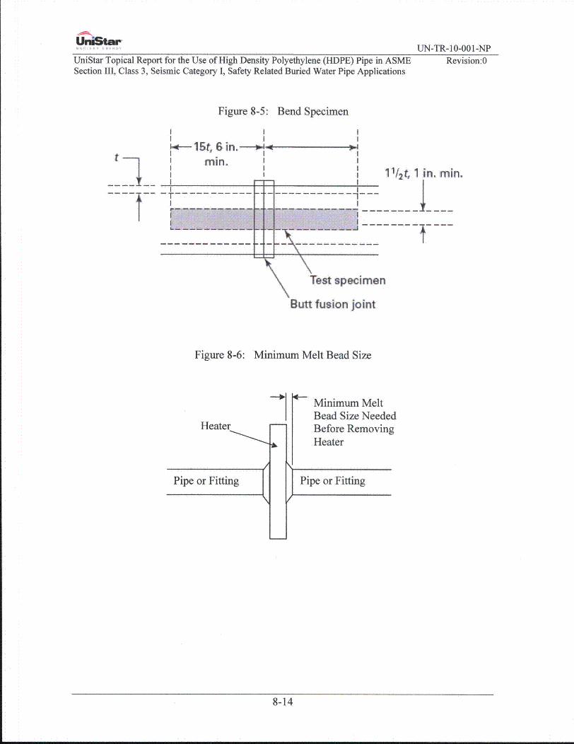
-AML,
U.niStar-UN-TR- 10-001-NP
UniStar Topical Report for the Use of High Density Polyethylene (HDPE) Pipe in ASMESection III, Class 3, Seismic Category I, Safety Related Buried Water Pipe Applications
Revision:0
Figure 8-5: Bend Specimen
t11/ 2t, 1 in. min.
------------- H+-'N' ---------Test specimen
Butt fusion joint
Figure 8-6: Minimum Melt Bead Size
4-
Heater
Pipe or Fitting
Minimum MeltBead Size NeededBefore RemovingHeater
Pipe or Fitting
/
8-14

UniStar-NUCLEAR ENERGY UN-TR- 10-001-NP
UniStar Topical Report for the Use of High Density Polyethylene (HDPE) Pipe in ASME Revision:0Section III, Class 3, Seismic Category I, Safety Related Buried Water Pipe Applications
8.7 Fusion Procedure Qualifications
8.7.1 General
Each manufacturer or contractor shall prepare Fusion Procedure Specifications (FPS)that are defined as follows:
A. A FPS is a written qualified fusing procedure prepared to provide direction formaking production fused joints to the requirements of this TR.
B. The completed FPS describes all essential variables for the fusion process usedin the FPS. The essential variables are listed in Section 8.6.1. The manufactureror contractor may include any other information in the FPS that may be helpfulin making a fused joint.
C. Changes in essential variables require re-qualification of the FPS.
D. The information required to be in the FPS may be in any format, written ortabular, to fit the needs of each manufacturer or contractor, as long as Form TR-2has been provided as a guide for the FPS. This Form includes the required datafor the fusion process and is located in Appendix A.
E. The FPS used for production fusing shall be available for reference and reviewby the Authorized Nuclear Inspector at the fabrication or installation site.
8.7.2 Manufacturer's Responsibility
A. Each manufacturer or contractor shall list the parameters applicable to fusing thathe performs in construction of fusion joints made in accordance with this TR.These parameters shall be listed in the FPS.
B. Each manufacturer or contractor shall qualify the FPS by the fusing of testcoupons, testing of specimens cut from the test coupons, and recording fusingdata and test results in the Procedure Qualification Record (PQR). The fusionmachine operators used to produce the fused joints to be tested for qualificationof procedures shall be under the full supervision and control of the manufactureror contractor during the production of these test fused joints. The fused joints tobe tested for qualification of procedures shall be fused either by direct employeesor by individuals engaged by contract for their services as fusion machineoperators under the full supervision and control of the manufacturer orcontractor. It is not permissible for the manufacturer or contractor to have thesupervision and control of fusing of the test fused joints performed by anotherorganization. It is permissible, however, to subcontract any or all of the work ofpreparation of test material for fusing and subsequent work on preparation of testspecimens from the completed fused joint, performance of nondestructiveexamination, and mechanical tests, provided the manufacturer or contractoraccepts the responsibility for any such work.
C. This Topical Report recognizes a manufacturer or contractor as the organizationwhich has responsible operational control of the production of the fusion joints.If in an organization effective operational control of fusing procedure
8-15

UniStar-.UCLEAR ENERGY UN-TR-10-001-NP
UniStar Topical Report for the Use of High Density Polyethylene (HDPE) Pipe in ASME Revision:OSection III, Class 3, Seismic Category I, Safety Related Buried Water Pipe Applications
qualification for two or more companies of different names exists, the companiesinvolved shall describe in their Quality Control System/Quality AssuranceProgram and the operational control of procedure qualifications. In this caseseparate fusion procedure qualifications are not required, provided all otherrequirements of this Section are met.
D. Except as noted in Section 8.7.3.(A).(1), the manufacturer or contractor shallcertify that he has qualified each FPS, performed the procedure qualificationtests, and documented it with the necessary Procedure Qualification.
8.7.3 Fusion Procedure Specifications
Butt fusion requirements, including process controls, are described in Sections 8.6thru 8.10. PPI TR-33 and ASTM F2620, were used as the basis for developing buttfusion requirements.
A. Standard Fusion Procedure Specification
B. When the FPS is limited to the following parameters, qualification testing is notrequired. If the manufacturer or contractor deviates from the conditions listedbelow, procedure qualification testing specified in Sections 8.6.2, 8.7.3.D, and8.7.4 is performed.
1) The pipe is limited to the horizontal position, ±45'.
2) Pipe ends are faced to establish clean, parallel mating surfaces that areperpendicular to the pipe centerline on each pipe end. When the ends arebrought together, there shall be no visible gap.
3) The outside diameters of piping components to be fused shall be aligned asaccurately as practical within existing commercial tolerances on diameters,wall thicknesses, and out of roundness. Alignment shall be preserved duringfusion. The external misalignment of the ends to be joined shall not exceed1/16". A gauge will be used to verify that this tolerance is met. The fusionmachine which grips the pipe shall be adjusted vertically to ensure thecenterlines of each pipe are parallel to each other within the 1/16" tolerance.
4) The drag pressure will be measured and recorded. The fusion pressure will becalculated so that an interfacial pressure of 60 to 90psig is applied to the pipeends.
5) The heater plate surface temperature shall be 400'F to 4507F measured atfour locations approximately 900 apart on both sides immediately prior toinsertion of the heater plate in the fusion machine.
6) The heater plate shall be inserted into the gap between the pipe ends andfusion pressure shall be applied and maintained until an indication of melt isobserved around the circumference of the pipe. The pressure shall be reducedto drag pressure and the fixture shall be locked in position so that no outsideforce is applied to the joint during the soak time.
8-16

UniStar'............. UN-TR-10-001-NP
UniStar Topical Report for the Use of High Density Polyethylene (HDPE) Pipe in ASME Revision:0Section III, Class 3, Seismic Category I, Safety Related Buried Water Pipe Applications
7) The ends will be held in place until the following bead size, shown in Table8-2 is formed during the heat soak cycle between the heater faces and thepipe ends.
Table 8-2: Approximate Melt
Pipe Size, (Diameter), in. Bead Size, in.< 3 IPS 1/16
> 3IPSto< 8 IPS 3/16> 8 IPSto< 12 IPS 1/4> 12 IPS to< 24 IPS 3/8> 24 IPS to < 36 IPS 7/16> 36 IPS to < 54 IPS 9/16
8) After the proper bead size is formed, the machine will be opened and theheater removed. The pipe ends will be brought together and the fusionpressure reapplied.
9) The maximum time from removal of the heating plate until the pipe ends arepushed together shall not exceed the times given in Table 8-3.
Table 8-3: Maximum Removal TimePipe Wall Thickness, in. Max. Heater Plate Removal Time
0.20 to 0.36 8 sec> 0.36 to 0.55 10 sec> 0.55 to 1.18 15 sec> 1.18 to 2.5 20 sec> 2.5 to 4.5 25 sec
Material Manufacturer Facility> 1.18 to 2.5 40 sec> 2.5 to 4.5 50 sec
10) The fusion pressure is maintained until the joint has cooled after which thepipe can be removed from the fusion machine. The cooling time underpressure shall be 30 to 90 seconds per inch of pipe diameter. When the wallthickness is greater than 2 inches, use 90 seconds per inch of pipe diameterfor the cooling time.
C. Essential Variables for Fusion Procedure Specification (FPS)
Any change in essential variable listed in Section 8.6.1 .A, requiresrequalification of the FPS.
8-17

UCLERr" UN-TR- 10-001-NP
UniStar Topical Report for the Use of High Density Polyethylene (HDPE) Pipe in ASME Revision:0Section III, Class 3, Seismic Category I, Safety Related Buried Water Pipe Applications
D. Testing Procedure to Qualify the FPS
1) Use 8 in. IPS DR 1I pipe size as a minimum for the qualification test of buttfusion joints.
2) Make the following butt fusion joints using the following combinations ofheater temperature ranges and interfacial pressure ranges and the FPS:
N High heater surface temperature and high interfacial pressure, five joints.
0 High heater surface temperature and low interfacial pressure, five joints.
0 Low heater surface temperature and high interfacial pressure, five joints.
0 Low heater surface temperature and low interfacial pressure, five joints.
3) Evaluate three joints of each combination using the High Speed Tensileimpact tests per Section 8.6.2. All joints must fail in a ductile mode.
4) Evaluate two joints of each combination using the Sustained Pressure Testingper Section 8.6.2.B. All joints must pass this test.
8.7.4 Mechanical Tests
A. General Requirements
1) The type and number of test specimens that shall be tested to qualify an FPSfor a butt fusion joint are given in Section 8.7.3.D. If any test specimenrequired by Section 8.7.3.D fails to meet the applicable acceptance criteria,the test coupon shall be considered as failed.
2) When it can be determined that the cause of failure is not related to fusingparameters, another test coupon may be fused using identical fusingparameters.
3) Alternatively, if adequate material of the original test coupon exists,additional test specimens may be removed as close as practical to the originalspecimen location to replace the failed test specimens.
4) When it has been determined that the test failure was caused by an essentialvariable, a new test coupon may be fused with appropriate changes to thevariable(s) that was determined to cause the test failure.
5) When it is determined that the test failure was caused by one or more fusingconditions other than essential variables, a new set of test coupons may befused with the appropriate changes to the fusing conditions that weredetermined to cause the test failure. If the new test passes, the fusingconditions that were determined to cause the previous test failure shall beaddressed by the manufacturer to ensure that the required properties areachieved in the production fused joint.
8-18
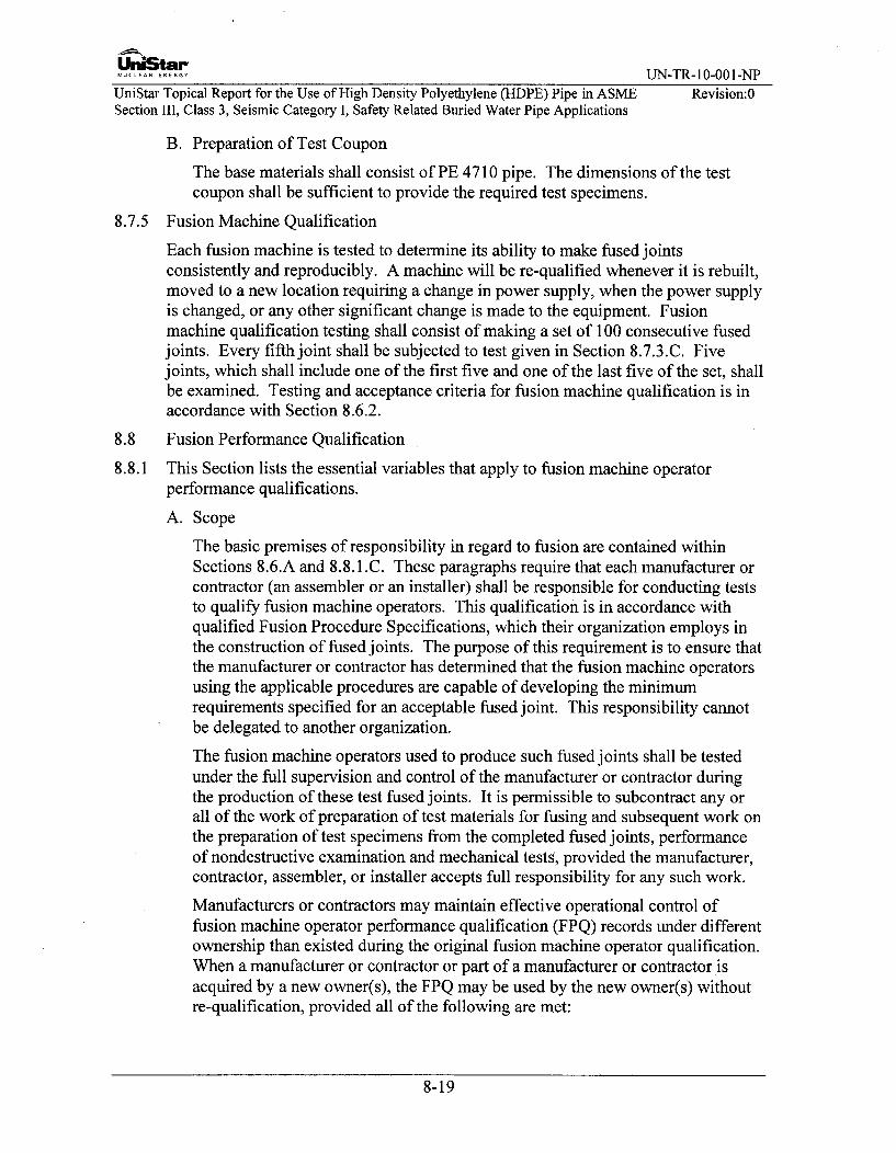
UniStar'NUCLEAR ENERGY UN-TR-10-001-NP
UniStar Topical Report for the Use of High Density Polyethylene (HDPE) Pipe in ASME Revision:0Section III, Class 3, Seismic Category I, Safety Related Buried Water Pipe Applications
B. Preparation of Test Coupon
The base materials shall consist of PE 4710 pipe. The dimensions of the testcoupon shall be sufficient to provide the required test specimens.
8.7.5 Fusion Machine Qualification
Each fusion machine is tested to determine its ability to make fused jointsconsistently and reproducibly. A machine will be re-qualified whenever it is rebuilt,moved to a new location requiring a change in power supply, when the power supplyis changed, or any other significant change is made to the equipment. Fusionmachine qualification testing shall consist of making a set of 100 consecutive fusedjoints. Every fifth joint shall be subjected to test given in Section 8.7.3.C. Fivejoints, which shall include one of the first five and one of the last five of the set, shallbe examined. Testing and acceptance criteria for fusion machine qualification is inaccordance with Section 8.6.2.
8.8 Fusion Performance Qualification
8.8.1 This Section lists the essential variables that apply to fusion machine operatorperformance qualifications.
A. Scope
The basic premises of responsibility in regard to fusion are contained withinSections 8.6.A and 8.8.1 .C. These paragraphs require that each manufacturer orcontractor (an assembler or an installer) shall be responsible for conducting teststo qualify fusion machine operators. This qualification is in accordance withqualified Fusion Procedure Specifications, which their organization employs inthe construction of fused joints. The purpose of this requirement is to ensure thatthe manufacturer or contractor has determined that the fusion machine operatorsusing the applicable procedures are capable of developing the minimumrequirements specified for an acceptable fused joint. This responsibility cannotbe delegated to another organization.
The fusion machine operators used to produce such fused joints shall be testedunder the full supervision and control of the manufacturer or contractor duringthe production of these test fused joints. It is permissible to subcontract any orall of the work of preparation of test materials for fusing and subsequent work onthe preparation of test specimens from the completed fused joints, performanceof nondestructive examination and mechanical tests, provided the manufacturer,contractor, assembler, or installer accepts full responsibility for any such work.
Manufacturers or contractors may maintain effective operational control offusion machine operator performance qualification (FPQ) records under differentownership than existed during the original fusion machine operator qualification.When a manufacturer or contractor or part of a manufacturer or contractor isacquired by a new owner(s), the FPQ may be used by the new owner(s) withoutre-qualification, provided all of the following are met:
8-19
Uni5tar-NUCLEAR...... UN-TR-10-001-NP
UniStar Topical Report for the Use of High Density Polyethylene (HDPE) Pipe in ASME Revision:OSection III, Class 3, Seismic Category I, Safety Related Buried Water Pipe Applications
1) New owner(s) takes responsibility for the FPQ
2) FPQ reflects the name of the new owner(s), and
3) Quality Control System/Quality Assurance Program reflects the source of theFPQ as being from the former manufacturer or contractor.
B. More than one manufacturer or contractor may simultaneously qualify one ormore fusion machine operators. When simultaneous qualifications areconducted, each participating organization shall be represented during fusing oftest coupons by an employee who is responsible for fusion machine operatorperformance qualification.
1) The FPSs that are followed during simultaneous qualifications shall becompared by the participating organizations. The FPSs shall be identical forall essential variables. The qualified thickness ranges for base material neednot be identical, but these thicknesses shall be adequate to permit fusing ofthe test coupons. Alternatively, the participating organizations shall agreeupon the use of a single FPS provided each participating organization has aFPS covering the range of essential variables to be followed in theperformance qualification. When a single FPS is to be followed eachparticipating organization shall review and accept that FPS.
2) Each participating organization's representative shall positively identify eachfusion machine operator who is being tested. Each organizationalrepresentative shall also verify marking of the test coupon with the fusionmachine operator's identification.
3) Each organization's representative shall perform a visual examination of eachcompleted test coupon and shall examine each test specimen to determine itsacceptability. Alternatively, after visual examination, when the test coupon(s)are prepared and tested by an independent laboratory, that laboratory reportmay be used as the basis for accepting the test results.
4) Each organizational representative shall complete and sign a fusion machineoperator FPQ record for each fusion machine operator. Data Report FormTR-2 has been provided as a guide for the FPS.
5) When a fusion machine operator changes employers between participatingorganizations, the employing organization shall verify that the fusionmachine operator's continuity of qualifications has been maintained (asrequired by Section 8.8.3B by previous employers) since his qualificationdate. If the fusion machine operator has had his qualification withdrawn forspecific reasons, the employing organization shall notify all otherparticipating organizations that the fusion machine operator's qualification(s)has been revoked in accordance with Section 8.8.4.A. The remainingparticipating organizations shall determine that the fusion machine operatorcan perform satisfactory work.
8-20

UniStar-NUCLEAR.E.ERY UN-TR-10-001-NP
UniStar Topical Report for the Use of High Density Polyethylene (HDPE) Pipe in ASME Revision:0Section III, Class 3, Seismic Category I, Safety Related Buried Water Pipe Applications
6) When a fusion machine operator's qualifications are renewed in accordancewith the provisions of Section 8.8.3.C, each renewing organization shall berepresented by an employee who is responsible for fusion machine operatorperformance qualification. The testing procedures shall follow the rules ofthis paragraph.
C. Tests
1) The performance qualification tests are intended to determine the ability offusion machine operators to make sound fused joints.
2) Each manufacturer or contractor shall qualify each fusion machine operatorfor the fusing process to be used in production. The performancequalification test shall be fused in accordance with a qualified FPS. Changesbeyond which re-qualification is required are given in Section 8.8.3.B.Allowable visual and mechanical examination requirements are described inSection 8.8.1 .E. Retests and renewal of qualification are given in Section8.8.3.
The fusion machine operator who prepares the FPS qualification test couponsmeeting the requirements of Section 8.7 is also qualified within the limits ofthe performance qualifications, listed in Section 8.8.1 .E for fusion machineoperators.
3) The record of fusion machine operator FPQ tests shall include the essentialvariables, the type of test and test results, and the ranges qualified inaccordance with Data Report Form TR-3 for each fusion machine operator.
D. Type of Test Required
1) All Mechanical tests shall meet the requirements prescribed in Section8.6.2.C.
2) Test butt fusion test coupons shall be fused as shown in Figure 8-3. The testspecimens shall be removed from the test butt fusion joint in accordance withFigure 8-5.
3) For pipe coupons all surfaces shall be examined visually per Section 8.3.1before cutting of bend specimens. Pipe coupons shall be visually examinedper Section 8.3.1 over the entire circumference, inside and outside. Theexamination shall evaluate the base material at least two inches from eachside of the joint.
E. Fusion Machine Operators
Each fusion machine operator who fuses under the rules of this section shall havepassed the mechanical and visual examinations prescribed in Section 8.8.1 .D.
F. Fused joints made in test coupons for performance qualification shall beexamined by mechanical and visual examinations (See Section 8.8.1 .D).
8-21

UniStar-NUCLEAR ENERG UN-TR-10-001-NP
UniStar Topical Report for the Use of High Density Polyethylene (HDPE) Pipe in ASME Revision:0Section III, Class 3, Seismic Category I, Safety Related Buried Water Pipe Applications
8.8.2 Qualification Test Coupons
A. The test coupons shall be pipe. Qualifications for pipe are accomplished byfusing one pipe assembly in the horizontal axis position (Figure 8-3, HorizontalAxis Position). The minimum pipe size shall be IPS 6.
8.8.3 Retests and Renewal of Qualification
A. Retests
A fusion machine operator who fails one or more of the tests prescribed inSection 8.8.1 .E, as applicable, may be retested under the following conditions:
1) When the qualification coupon has failed the visual examination of Section8.8.1 .D, retesting shall be by visual examination before conducting themechanical testing.
When an immediate retest is made, the fusion machine operator shall maketwo consecutive test coupons all of which shall pass the visual examinationrequirements.
The examiner may select one of the successful test coupons from each set ofretest coupons which pass the visual examination for conducting themechanical testing.
2) When the qualification coupon has failed the mechanical testing of Section8.8.1 .D, the retesting shall be mechanical testing.
When an immediate retest is made, the fusion machine operator shall maketwo consecutive test coupons which shall pass the test requirements.
3) When the fusion machine operator has had further training or practice, a newtest shall be made.
B. Expiration and Renewal of Qualification
The performance qualification of a fusion machine operator shall be affectedwhen one of the following conditions occurs:
1) When they have not fused with a process during a period of six months ormore, their qualification for that process shall expire.
2) Any fusion machine operator who makes a fusion joint that fails hydrostatictest will immediately lose their qualifications for fusion and be required torepeat the training course as well as be re-qualified.
3) When there is a specific reason to question an'operator's ability to makefused joints that meet the specification, the qualifications that support thefusing being performed shall be revoked.
C. Renewal of Qualification
1) Renewal of qualification expired under 8.8.3.B may be made by fusing asingle test coupon and by testing of that coupon as required by Section
8-22

UnOStar-NUCLEAR.E.ERY UN-TR-10-001-NP
UniStar Topical Report for the Use of High Density Polyethylene (HDPE) Pipe in ASME Revision:0Section III, Class 3, Seismic Category I, Safety Related Buried Water Pipe Applications
8.8.1 .C. A successful test renews the fusion machine operator's previousqualifications for the process for which he was previously qualified.
2) Fusion machine operators whose qualifications have been revoked underSection 8.8.3.B above shall re-qualify. Qualification shall utilize a testcoupon appropriate to the planned production work. The coupon shall befused and tested as required by Section 8.8.1 .C and 8.8.1 .D. Successful testrestores the qualification.
8.8.4 Fusion Variables for Fusion Machine Operators
A. General
A fusion machine operator shall be re-qualified whenever a change is made inone or more of the fusion machine variables.
1) A change in pipe diameter from one range to another;
(1) Less than IPS 8"(2) IPS 8" to IPS 24"(3) IPS over 24"
2) A change in name of the manufacturer of equipment
3) The axis of the pipe is limited beyond the horizontal position ±45'.Qualification in any position other than horizontal qualifies the orientationtested + 200.
8.8.5 Testing
A. Test joints shall be IPS 8" DR 1I for testing at a minimum. A data acquisitionrecorder shall be attached to the fusion machine and the data concerning the jointentered. The data acquisition device shall be used to record data required bySection 8.6.1.A.
B. The supervisor conducting the test shall observe making of the butt fusion jointand note if the FPS was followed.
C. The completed joint shall be visually examined and meet the acceptance criteriaof Section 8.3.1
D. After the joint is complete the data acquisition record shall be reviewed by theassessor and compared to the FPS to ensure the proper procedures werefollowed.
E. The test specimens shall be removed, tested and meet the acceptance criteria inaccordance with Section 8.6.2.C.
8-23

-:9ýUniStarNUCLEAR ENERGY UN-TR- 10-00 1 -NP
UniStar Topical Report for the Use of High Density Polyethylene (HDPE) Pipe in ASME Revision:OSection 111, Class 3, Seismic Category 1, Safety Related Buried Water Pipe Applications
8.9 Fusion Machine Operator Qualification Training
It is important that the fusion machine operators are trained and competent in thefusion technology employed in constructing PE piping systems. Continuedcompetence of the fusion operator is covered by periodic retraining andreassessment.
This section provides guidance for the training, assessment and approval of fusionmachine operators-. This section covers both the theoretical and practical knowledgenecessary to ensure high quality fusion joints.
8.9.1 Training Course
A. A trainee fusion operator for PE systems will complete a training course in orderto obtain a fusion operator certificate. The course will cover all aspects of thebutt fusion process including safety, machine evaluation and maintenance,machine operation, FPS guidelines, pressure and temperature setting, data logdevice operation and set-up, visual examination guidance, and data log recordevaluation. The minimum course duration is 24 hours.
B . The course will be delivered by a competent qualified trainer with a minimum ofthree years of experience in the butt fusion processes and who has mastered thetechniques involved.
C. The trainer should have a range of fusion machines representative of theequipment encountered on worksites for installing pipes, in order for the traineefusion operator to become acquainted with the fusion equipment commonly used.The trainee fusion operator may be trained on one of these fusion machines or ona machine from the parent company. The fusion equipment must comply withthe fusion machine manufacturer's specifications and/or ISO 12176-1 "PlasticsPipes and Fittings - Equipment for Fusion Jointing Polyethylene Systems - Part1: Butt Fusion."
8.9.2 Operator Assessment
The trainee fusion operator who has completed a training course as described abovewill then pass a theoretical and practical assessment in order to be qualified as afusion operator for PE systems. The assessor should not be the trainer, but shouldhave the same assessment qualifications as the trainer.
8.9.3 Training Curriculum
A. The training course should comprise of any combination of fusion packagesbased on the requirements of utility or pipeline operators. These packages maybe given as individual modules or combined to suit requirements.
B. The pipes and fittings to be used shall conform to the ASTM product formspermitted by this Topical Report.
C. The lessons will be designed so that the trainee fusion operator learns to masterthe fusion technique and attains a good working knowledge of the piping systemmaterials and practical problems encountered when fusing pipe in the field. The
8-24

Un•Star"NUCLEAR ENERGY UN-TR-10-001-NP
UniStar Topical Report for the Use of High Density Polyethylene (HDPE) Pipe in ASME Revision:0Section III, Class 3, Seismic Category I, Safety Related Buried Water Pipe Applications
fusion operator will receive a written manual covering the elements contained inthe training.
D. The theoretical course will include general information pertaining to rawmaterials, pipes and fittings, and will also include knowledge about preparation,tools, and devices, joining components, different materials, different diameterratios and correct and incorrect parameters. The safety course will includeinformation concerning the fusion process, such as protective clothing, generalsafety, regulations for electrical equipment, handling heater plates, etc. Areas ofstudy will include the following:
1) Butt fusion joining.
* Principles of fusion.
* Straight/coiled pipes, service lines, main lines, etc.
* Components: pipes, flange adapters saddle fittings, other fittings.
* Butt fusion equipment: manual, semi-automatic and automaticmachines.
* Joint preparation: cleaning, rounding, alignment, facing, etc.
* Butt fusion cycle: pressure, time and temperature relationships,diagram.
" Failure modes: understanding and avoiding possible errors.
" Test methods: visual examination, high speed tensile-impact test,bending test, hydrostatic test, data log recording/evaluation, etc.
2) The trainee fusion operator should be familiar with the butt fusion joiningtechnique and procedure by making a sufficient number of butt fusion joints.In some cases, the fusion technique may vary slightly according to diameter,material or other factors. In such cases, the trainee fusion operator shouldalso be made familiar with the various techniques.
3) The trainee should start by making a butt joint between two pipes, and shouldthen learn to make butt fusion joints with pipes and fittings such as tees,reducers, etc.
8-25
UniStar-NUCLEAR ENERGY UN-TR- 10-001-NP
UniStar Topical Report for the Use of High Density Polyethylene (HDPE) Pipe in ASME Revision:0Section III, Class 3, Seismic Category I, Safety Related Buried Water Pipe Applications
4) The trainee should learn how to detect and avoid typical fusion defects.
5) The trainee should learn how to assess the quality of a butt fusion joint bydoing a visual examination of the butt fusion joint and comparing it to thevisual guidelines published in the pipe manufacturer's heat fusion joiningprocedure booklet. The trainee should also compare the data log record tothe FPS to ensure the proper parameters and procedures were followed in thebutt fusion process.
8.9.4 Assessment and Testing
A. Training program will end with a theoretical and practical examination.
B. The content of the theoretical examination shall consist of not less than twentymultiple choice questions about the butt fusion process, fusion machineoperation, pipe, quality examination, safety, etc. within a set period of time. Ascore of 80% or better is considered passing on this examination. Questions tobe included, but not limited to, are:
" How do you calculate the fusion machine gauge pressure?
* What is the proper heater surface temperature range from the FPS?
• What is the proper butt fusion interfacial pressure range from the FPS?
" How is drag pressure calculated?
" When is the heater to be removed during the heating cycle?
" How long are the pipe ends to remain together under pressure in the coolingcycle?
• What is the difference between IPS pipe and DIPS pipe?
* How is the hydraulic fusion machines total effective piston area determined?
* How is the total effective piston area of the fusion machine used to determinethe fusion machines gauge pressure for a specific pipe?
* How can the machine be adjusted to improve the alignment of the pipe afterfacing?
* How much material should be removed from the pipe ends in the facing
operation?
• Does the fusion machine conform to the equipment manufacturer'sspecifications?
* How is the pipe to be aligned in the butt fusion machine?
* What is interfacial pressure?
C. The practical examination will require the trainee to make a fusion joint with ahydraulic butt fusion machine with a minimum pipe size of 6 in. IPS DR11. Adata acquisition device must be attached to the fusion machine and the dataconcerning the joint entered. The data log device shall be used to record the joint
8-26

UniStar-- r"4 UN-TR- 10-001-NP
UniStar Topical Report for the Use of High Density Polyethylene (HDPE) Pipe in ASME Revision:0Section III, Class 3, Seismic Category I, Safety Related Buried Water Pipe Applications
made by the trainee. The assessor shall observe the butt fusion joint and note ifthe proper procedure was followed. After the joint is complete, the data logrecord shall be reviewed by the assessor and compared to the FPS to ensure theproper procedures was followed. The assessor will then conduct a visualexamination of the joint to make sure it satisfies the pipe manufacturersrecommended visual guidance criteria.
D. If a data log device is not available, the assessor will manually record the buttfusion parameters used in the butt fusion process. This will be compared withthe FPS to ensure they agree.
E. Trainee fusion operators who pass the theoretical and practical examinationreceive a fusion operator certificate bearing the logo of the assessment centerawarding the approval. The fusion operator certificate will state the techniqueand fusion machines for which the operator is qualified.
8.9.5 Reassessment
If the trainee fails one of the examinations, a re-examination will be available after aperiod not shorter than one week. If the trainee fails the examination for the secondtime, the trainee should repeat the training course before taking the test again.
8.10 Data Acquisition Log Review
Review both the recorded log information and the pressure/time graph to evaluate ifthe proper procedure was followed. The following examples are shown to assist inthis evaluation:
8.10.1 Recorded Data Log Information Correct Procedure. All job information must beentered. All essential variables listed in Section 8.6.1 .A. 1 shall be documented onthe Recorded Data Log. All essential variables must be within the qualified range.
8.10.2 Pressure/Time Graph Evaluation. No Errors (see Figure 8-7, Typical Time/PressureDiagram of a Butt Fusion Weld).
A. P1: Drag Pressure. Fusion machine mechanical drag plus pipe drag. Pressuremay drop to Opsi during soak cycle (psi gauge).
B. P2: Fusing Pressure. Calculated machine fusion gauge pressure plus dragpressure.
C. TI: Initial Heater Contact Time at Fusion Pressure. Time required to observe anindication of melt around the pipe circumference.
D. T2: Heat Soak Time. Time required to develop the size of melt bead against theheater specified in the procedure.
E. T3: Heater Removal Time. Time required to open the fusion machine, removethe heater and bring the pipe ends together at fusion pressure. The time must notexceed the time in the specification.
8-27

UniStar'............. UN-TR-10-001-NP
UniStar Topical Report for the Use of High Density Polyethylene (HDPE) Pipe in ASME Revision:0Section III, Class 3, Seismic Category I, Safety Related Buried Water Pipe Applications
F. T4: Cool Time. Time required to cool the joint at fusion gauge pressure. Thismust be 30-90 seconds per inch of pipe diameter. Use 90 seconds per inch ofpipe diameter for any pipe diameter with a wall thickness greater than 1.50 in.
8.10.3 Correct Procedure. The following requirements apply (see Figure 8-8, CorrectProcedure):
A. Review if P1 and P2 recorded gauge pressures agree with the specified fusionprocedure. P2 can drop to zero during the heat soak cycle.
B. Review if P2 is maintained for 30-90 seconds per inch of pipe diameter duringthe fuse/cool cycle.
C. On large diameter heavy wall pipe it sometimes takes several minutes to see anindication of melt around the circumference of the pipe, so the initial contacttime against the heater at fusion gauge pressure is usually longer than normal.Make sure the heat soak time is longer than the initial contact time.
Figure 8-7: Typical Time/Pressure Diagram of a Butt Fusion Joint
T1 T2 1 T3 T4
- - i I P2
U)V.
U)ci,
- - - - ----------- DI
Time ISeconds)
8-28

UniStarNUCLEAR ENERGY UN-TR- 10-001-NP
UniStar Topical Report for the Use of High Density Polyethylene (HDPE) Pipe in ASMESection III, Class 3, Seismic Category I, Safety Related Buried Water Pipe Applications
Revision:0
Figure 8-8: Correct Procedure
Ce
5)
(NN,5)
0~
Time (Seconds)
Figure 8-9: Incorrect Procedure
N
Tmse (Seconds)(a)
- m m
lime (Seconds,
S
S
Tim. (econds)(c)
Time (Seconds)(d)
1- - 7- -
Time ISeconds)(W)
8-29

UniStar"NUCLEAR ENERGY UN-TR- 10-001 -NP
UniStar Topical Report for the Use of High Density Polyethylene (HDPE) Pipe in ASME Revision:0Section III, Class 3, Seismic Category I, Safety Related Buried Water Pipe Applications
8.10.4 General Notes:
A. No Heat Soak Time: Pressure not reduced at start of Heat Cycle.
B. No Heat Soak Time: Pressure maintained during Heat Soak Cycle.
C. Heat soak time is very short. Do a visual examination of the bead size to makesure it is within the butt fusion specifications.
D. The specified fusion gauge pressure was not applied during the Fuse/Cool cycle.The Fuse/Cool Times does not appear long enough.
E. Fusion gauge pressure not maintained in the Fuse/Cool cycle for the time in thespecification.
8.11 HDPE ITAAC
It is proposed that ITAAC be developed to verify that as-built HDPE satisfies thedesign and performance standards specified in the COL. The type of informationand level of detail included in the ITAAC for HDPE pipe should be based on agraded approach that is commensurate with the safety-significance of the SSCs. TheITAAC will be developed to verify HDPE design information including the principalperformance characteristics, their important features in this Topical Report, and itsfunctions for defense-in-depth.
Section C.II. 1.2.3 of Regulatory Guide 1.206 provides specific guidance on ITAACdevelopment for piping systems and components. Regulatory Guide 1.206generically applies ITAAC to verify requirements of the ASME Code. RegulatoryGuide 1.206 is used as a basis to apply the appropriate requirements of this TopicalReport into ITAAC. ITAAC items that are to be incorporated, changed or applicableas currently recommended are described in the following sections. These ITAACensure that the HDPE piping is constructed and will operate in conformity with thedesign.
8.11.1 ITACC Revisions related to HDPE Piping
As a result of using HDPE piping in ASME Section III, Class 3 buried pipingapplications, several ITAAC items will be added that should reference this TopicalReport.
For Class 3 piping, ITAAC are developed to verify the welding quality of as-builtpressure boundary welds. Since HDPE pipe cannot be welded the way metallic pipecan, an equivalent ITAAC will be developed to demonstrate the acceptability of thebutt fusion joints used to join lengths of HDPE pipe. The ITAAC shall require thatpressure boundary fusion joints in the specified safety system(s) will be designedand constructed in accordance with this Topical Report. Inspections will beconducted of the as-built piping joints to assure the Topical Report requirementshave been met.
8-30

nUniStarE UN-TR-10-001-NP
UniStar Topical Report for the Use of High Density Polyethylene (HDPE) Pipe in ASME Revision:0Section 1II, Class 3, Seismic Category I, Safety Related Buried Water Pipe Applications
It is standard to have an ITAAC to verify that components are procured, inspected,analyzed, and installed in conformance with ASME Code. Since this Topical Reportcontains the appropriate criteria for these processes, (including the ASME Coderequirements), reference to this Topical Report will be specified for ITAACpertaining to HDPE piping. Analysis will be performed in accordance with theTopical Report design requirements as specified in the Design Specification andcompliance documented in a stress report. Piping shall be constructed and installedin accordance with the Topical Report requirements and certified in a Data ReportForm. Shop and field inspections of the as-built piping will be performed by anAuthorized Nuclear Inspector and certified on a Data Report Form.
An ITAAC will be added to specify that the performance, inspections anddocumentation of hydrostatic testing of the specified system(s) that contains HDPEpiping will be in accordance with this Topical Report. Inspections of the as-builtpiping will be conducted to assure the Topical Report requirements have been met.
Typically, there is an ITAAC that provides for ensuring that protective measureshave been applied to buried Seismic Category I pipe, such as a protective waterproofwrapping or coating. Due to the material properties of HDPE pipe, wrapping orcoating is not necessary. Therefore, any existing ITAAC that address this issue, willbe denoted as being applicable to only metallic pipe.
It is important that the materials used in systems that interface with brackish waterare suitable for that environment. ITAAC currently specify metallic piping materialin these applications, such as SA-106 Grade B carbon steel or SB-575 stainless steel.Any existing ITACC that address that issue will be revised to include the use of PE4710 material as an additional acceptable material.
8.11.3 Applicable As-Is ITAAC for HDPE Piping
Other ITAAC requirements that are currently proposed for Class 3 piping will alsoapply to HDPE piping and do not require supplementing; these include:Demonstration that the piping is capable of withstanding a design basis seismic loadwithout loss of safety function; inspections of the as-built piping to ensure thelocation is in accordance with the design, and; the ability to withstand design basisloads without loss of integrity.
8-31
U'n0SklUniStarNUCLEAR ENERGY UN-TR-10-001-NP
UniStar Topical Report for the Use of High Density Polyethylene (HDPE) Pipe in ASME Revision:0Section 1II, Class 3, Seismic Category I, Safety Related Buried Water Pipe Applications
9.0 DESIGN LIFE
This section demonstrates the adequacy of HDPE 4710 pipe for a 60 year service lifewith design conditions up to 200psig and 140'F, and with a possible short durationhigh temperature transient of 160'F for 30 days.
9.1 60 Year Design Life Determination
PE piping strength capacities vary with time when under high stresses (stresses at orclose to the HDS), therefore, a design life is specified for HDPE piping systems,however, various industry standards do not limit HDPE pipe design life when thepipe wall thickness is calculated for the system design pressure and HDS is based onthe system design temperature.
ASME Section III, Class 3 PE 4710 piping is sized and rated for at least 60 years ofcontinuous operation (60 year design life) at the specified design pressures anddesign temperatures (between 73°F and 140'F).
ASTM and PPI standards (PPI TR-4 & ASTM D2837) list PE 4710 HDB(Hydrostatic Design Basis) values at 73°F and 140'F. These values are based onsubstantiation and validation (based on accelerated high temperature testing) thatpipe stress rupture data confirm the 73°F regression curve is linear to 50 years andbeyond (beyond the 438,000 hours intercept, see Figure 9-1, 140'F curve).
The pipe stress rupture regression curve is a linear logarithmic plot of hoop stress(Y-axis) versus time (X-axis) at a specified temperature. High stress data pointshave short rupture times, while low stress data points have longer rupture times.
The PPI Handbook of PE Pipe provides an equation which is used to interpolatebetween 737F and 140'F to derive the HDB for intermediate temperatures.
The PE 4710 HDB at the 100,000 hours (11.4 years) intercept is multiplied by aDesign Factor (DF) of 0.50 to derive the HDS (Hydrostatic Design Stress). This DFis more conservative than the DF of 0.63 listed in ASTM and PPI standards.
In addition to accounting for various manufacturing variables, use of the DF ensuresthat the long term maximum allowable stress (HDS) will always be significantlybelow LTHS at 50 years. This, together with confirmation that the 73°F regressionis linear to 50 years and beyond (beyond the 438,000-hour intercept), establishes thelong term maximum allowable stress (HDS).
Industry regression curves are usually only generated out to the 50 year intercept. Areview of a typical 73°F linear regression curve for PE 4710 pipe shows that theLTHS at the 438,000-hour (50 years) intercept is approximately 100psi lower thanthe 1600psi HDB at the 100,000-hour intercept (see Section 9.4 for typical linearregression curves). Use of a Design Factor (DF) of 0.50 gives an HDS of 800psiwhich is 700psi lower than the 50-year LTHS.
Similarly, the 140'F PE 4710 linear regression curve shows that the LTHS at the438,000-hour intercept of 916psi is approximately 84psi lower than the 1000psi
9-1

IUN-TR- 10-001 -NP
UniStar Topical Report for the Use of High Density Polyethylene (HDPE) Pipe in ASME Revision:0Section III, Class 3, Seismic Category 1, Safety Related Buried Water Pipe Applications
HDB at the 100,000-hour intercept. Use of a Design Factor (DF) of 0.50 gives anHDS of 500psi which is 416psi lower than the 50-year LTHS.
To determine how much lower a 60-year LTHS would be, typical PE 4710 linearregression curves for 73'F and 140'F were extrapolated beyond the 438,000-hour(50-year) intercept, to the 525,600 hours (60 years) intercept by using the three-coefficient Rate Process Method (RPM) described in Section 9.4.
It was determined that at the 60-year intercept the 73'F LTHS is lOpsi lower, and the140'F LTHS is 7psi lower, than at the 50-year LTHS intercept (see Appendix C).Similar results for a 60-year LTHS are reported in EPRI Report 1013549,Nondestructive Evaluation: Seismic Design Criteria for Polyethylene PipeReplacement Code Case.
Below is a typical 140'F linear regression curve for PE 4710 pipe that shows its100,000-hour intercept (indicating HDB of 1000psi). Its 438,000-hour (50-year) and525,600 hour (60 years) intercepts are also shown. The straight horizontal lineshown below it represents the 140°F HDS of 500psi (HDS = HDB x 0.5DF)
Figure 9-1: 140'F Regression Curve for PE4710
Typical Regression Curve
1200.00
1000.00
" 800.000-e- 140°F Linear Reg Curve
w600.00 A 11.4 year HDB (1000psi)
-. A 50 year LTHS (916psi)0400.00= A 60 year LTHS (909psi)
200.00 0.5 x HDB @ 50 years (500psi)
0.00,1.OE+04 1.OE+05 1.OE+06 1.OE+07
Time to Failure (hrs)
When expressed as a percent change the 60 year LTHS reduction of 10 psi is 0.6%(10psi/1600psi = 0.6%, 7psi/1000psi = 0.7%). This could be construed as a 0.6%reduction in the allowable stress, however, the allowable stress is based on the 11.4year intercept and remains unchanged. In addition, this reduction in LTHS is morethan adequately covered by the 20% margin that is provided when the pipe wall isbased on a conservative design pressure, and operates under lower normal operatingpressures and stresses (see Section 9.2). Additional margin is also provided by
9-2

UniStar"NUCLEAR ENERGY UN-TR-10-001-NP
UniStar Topical Report for the Use of High Density Polyethylene (HDPE) Pipe in ASME Revision:0Section III, Class 3, Seismic Category I, Safety Related Buried Water Pipe Applications
normal operating temperatures that are lower than the design temperature. Theselow temperatures significantly increase the LTHS for operation with the much lowernormal operating pipe stresses.
In addition, this Topical Report requires a PENT rating of at least 2000hrs. Asexplained in Section 3.9, this high PE 4710 PENT value ensures Slow Crack Growthbrittle failure will not occur for 60 plus years shown on the PE4710 regression curve.Therefore, the PE 4710 pipe can be safely designed to operate for over 60 yearsunder normal operating conditions.
9.2 Minimum Wall Thickness
The HDS is the maximum allowable hoop stress for the specified temperature, and isused to calculate the required pipe minimum wall.
Conservative design pressures and design temperatures have been selected tocalculate the required pipe minimum wall. These design parameters envelopemaximum operating conditions that are of a very short duration and have muchhigher pressures and/or temperatures than the normal operating conditions. Toensure a conservative design pressure is used, it will be required that the designpressure be at least 1.20 times the normal operating pressure. In addition, the DesignTemperature shall be 10°F higher than normal operating temperature.
For buried ASME Section III, Class 3 HDPE water piping, design conditions arebased on maximum operating conditions that are due either to a DBA, the system'spump shutoff head, extreme ambient conditions, or combination of these events.
In assessing whether the PE 4710 pipe has been adequately designed for a 60-yearservice life, one must consider the duration it will operate under the high stressconditions used to select its pipe wall thickness. During normal operatingconditions, the selected pipe wall will be subjected to a much lower stress.
It is possible that an industry standard pipe wall will be selected (DR6, DR7, DR9,DR 11, etc.) that results in a hoop stress exactly equal to the PE 4710 HDS underdesign conditions, however, the calculated pipe minimum wall is usually slightly lessthan the standard wall selected and the pipe stress under design conditions is usuallyslightly lower than the HDS for the design temperature. With the selected pipe wallone can operate continuously under design conditions for the 60-year service life. Ifdesign conditions occur for no more than one month during the 60-year life of theplant (0.14% of the time) then normal operating conditions will exist 99.86% of thetime.
With the pipe wall selected for design conditions, the pipe stress under normaloperating conditions will be at least 25% less than the HDS for the normal operatingtemperature. Under these lower stress conditions the pipe has a much longer designlife than the 60 year service life.
To demonstrate this, the three coefficient Rate Process Method (RPM) equationgiven in ASTM D 2837 Paragraph 5.6.1.2 (and described in PPI TN-16/2008) withcoefficients derived from the typical PE 4710 linear regression curves noted in
9-3

Urti5tar-NUCLEAR ENERGY UN-TR-10-001-NP
UniStar Topical Report for the Use of High Density Polyethylene (HDPE) Pipe in ASME Revision:0Section III, Class 3, Seismic Category I, Safety Related Buried Water Pipe Applications
Section 9.1, is used to calculate the time to rupture for various typical "low stress /low temperature" normal operating conditions (LTHS used in RPM equation equalstwo times the normal operating pipe stress).
Given the design margins noted above for the Design Temperature and Pressure, inall cases with typical normal operating conditions the time to failure exceeds 1000years (See methodology described in Appendix C).
9.3 Corrosion Allowance
No corrosion allowance is considered in the minimum wall thickness calculationused to select the pipe wall. HDPE will not rust, rot, pit, corrode, tuberculate orsupport biological growth.
A major advantage of HDPE is its virtual freedom from attack by soils, and byambient water and moisture. PE, being a non-conductor of electricity, is immune tothe electrochemical based corrosion process that is induced by electrolytes such assalts, acids and bases. In addition, PE piping is not vulnerable to biological attack,and its smooth, non-stick inner surface results in low friction factors and exceptionalresistance to microbiological influenced corrosion.
The biocides used will be similar to those successfully used in chlorinated potablewater HDPE piping systems. As noted in Jana Laboratories Technical Report"Long-Term Performance of PE Piping Materials in Potable Water Applications,"dated 9/17/2009, and listed in the PPI listing of "Municipal / IndustrialPublications;" with HDPE piping the chlorinated water oxidative process can takemany hundreds, even thousands, of years to occur.
The Jana report has projected HDPE piping performance based on acceleratedlaboratory testing per ASTM F2263, using the Rate Process Method for variouselevated temperatures and pressures, and potable water qualities, and found thatPE4710 pipe will have a potable water design life well beyond 100 years.
When burying pipe, clean bedding and back fill will be used to shield it fromcontaminated soil. Therefore, no corrosion allowance is required.
9.4 Design for Elevated Temperatures
In unusual circumstances, design conditions that occur for no more than one monthduring the 60 year plant life may require operation with a transient temperature up to160'F (exceeding the standard maximum temperature of 1407F). In evaluating sucha case the pipe wall thickness shall be based on a design temperature of 140'F.
The rate process method (RPM) equation is used to evaluate PE 4710 piping for this160'F temperature that is designed for a temperature of 140'F so that an excessivelythick pipe will not be required.
In order to address a temperature of 160'F, the 160'F HDB of 800psi must bederived (100,000-hour value for an LTHS between 760psi and 960psi per Table 1 ofASTM D2837). This 160'F, 800psi HDB is then validated per ASTM D2837, Table7.
9-4

UniStar-NUCLEAR ENERGY UN-TR- 10-001-NP
UniStar Topical Report for the Use of High Density Polyethylene (HDPE) Pipe in ASME Revision:0Section III, Class 3, Seismic Category I, Safety Related Buried Water Pipe Applications
The RPM equation with coefficients derived from typical PE 4710 linear regressioncurves for 73°F, 140'F and 176°F is used to derive the 160'F PE 4710 linearregression curve (See Appendix C) . This curve is then extrapolated to the 100,000-hour, the 438,000-hour (50-years), and the 525,600-hour (60-year) intercepts (the100,000-hour intercept confirms an 800psi HDB).
The RPM method can be used as a way to create a math model of the PE 4710 creeprupture regression curves, but not for the testing used to establish these curves. Thereare 4 different ASTM D2837 methods (Procedures I, II, III or IV, which include theRPM and ISO 9080 methods) that can be used for the testing to establish HDB's forvarious temperatures (73 0F, 1400F, 176°F, etc.)
The Rate Process Method uses the following equation. As explained in Appendix Cof EPRI report 1013549, for a given HDPE material one needs stress ruptureregression curve data for at least two temperatures and two stresses at two differentfailure times to determine the A, B, and C coefficients used in the RPM equation forthe HDPE material involved.
B C x LogS
T TWhere:t = slit mode failure time, hoursT = absolute temperature, RS = HDB hoop stress, psig
Once the three-coefficients are solved for, the equation can be used for the specificmaterial involved to solve for any one parameter if the other two are given (i.e.,given time and temperature, solve for stress).
As described in PPI TN- 16/2008, a number of state-of-the-art PE resins (bimodalPE4710), when properly extruded into pipe, will not exhibit slit mode failures inreasonable test times even when tested at the maximum temperature (ductile typefailure may occur). Therefore, the RPM procedure is not applicable for testing thesematerials except as a qualifying procedure to ensure, in fact, slit mode failures do notoccur.
Where regression curves have been established by using one of the other ASTMmethods, the RPM method can be used as a way to create a math model of thesecurves, even though it may not be suitable for testing purposes.
The regression curves are linear on a logarithmic grid, with the curves for eachtemperature parallel to one another. These curves can be used with the RPM methodto predict material performance for stress and temperature values that lie between thecurves, including the RPM extrapolation of these curves to a design life beyond 60years.
9-5

...... UN-TR-10-001-NPUniStar Topical Report for the Use of High Density Polyethylene (HDPE) Pipe in ASME Revision:0Section III, Class 3, Seismic Category I, Safety Related Buried Water Pipe Applications
Typical curves appear as follows:
ISO 9080 Regression Analysisper Becetel's Standard Extrapolation Method (SEM) Software
Alathon® L4904-Black
S23
.(i 4 i 11 L .-F -l l6080
] ~~~------ 1_ Ti Iif 1 1 7 lJ•I1Il~lItII11
I I'll ", ;-4 t; 0 VI U 1 0.5 MPaF* 00 t I- -L 14 FF 4 I _-1FF , _ F F F7'100 - t----4.-.4.I41- -_ - M S .- 10__. . .F.F .. .. . . . . . .. . . ..I F F Fi
0 I FIFIt F I FI FFI FFl I FFI I I F F F FFFF F FF FFF I I
T mo __ i T.. F-- f, - - j;- - j -i +- - ILI. ---I- --• --•-H.+ +- -. - •. - •,-- ----- -- 7 - • r ,•-+•M S =Ol
F F1I F1 F F F F F F I F F -I I IFF F tF.... 0 F T T F.... T- i i -FFF ---F F F-i - 7F . -FFFFF -7- F I -F755F -F1- 1 F iFF lF... . . . . .. .. . .. .1110
F.... .. IFF 1 1 F FFFF F F IF.,F IFFFFFFI fll 1 FIFIF F IF118•.100• F I F F IFF I FFFF F F l IFFI F F ll FIII F F FFFFFF F IlIFIF
114-i0i FFF IF F IF IF F IF F IF , I F lFFFF ,F IFFF Fll F F lt
120L llFFFF i FFFF F~ F IFIFIF F I IIFFF F I IFFFFIFI 1 I11 tlF.l•+L FFFF_. , t t FFFFF FI F IFFI IFI F I F 1F 11 F FF1I F tl I F f
F.r c F ifFI F F F IF IF F , FI FFIII FI F I111 FF I F !F1111 F F I FIFII I-i0I. I I II I I l I II I I I II IIIj IIA-100
1 04.1D i10 1I 12 t I i 1 104lll I D 10II 6II I~
b w!1tl ta to IIcy l 0ýl7 TIP I 10 a lu I I I! I I fl V!11 l
EPRI Report 10 13 549, updated September 2006, Appendix C, uses the RPM methodto predict the 60 year HDB for PB 3408 pipe (PB 3408 is not a bimodal highperformance PB material).
Per ASTM D2837 Table 7, the linear regression curve for 176'F is extrapolated tothe 37,500-hour intercept to confirm that this HDB exceeds the ASTM D2837 Table7 value required to validate an 800psi HDB. A Design Factor (DF) of 0.50 was usedto derive the 160'F HDS of 400psi.
To verify whether pipe with a wall thickness based on the 140'F HDS of 500psi(allowable pipe stress) can be used for the transient design temperature of 160'F, theRPM equation is used to calculate the pipe's time to rupture at 160'F with a pipestress of 500psi, given that this pipe stress is 100psi higher than the 160'F HDS of400psi (the design pressure is the same for both temperatures).
With this thinner pipe wall, the calculated time to rupture is 61 days. This 61-dayduration exceeds the one-month duration (one half of the 160'F design life) for anevent that occurs once in the 60-year plant life during which this 160'F designcondition exists.
As noted in Section 9.2, with a pipe wall selected for the 140'F design condition, thepipe stress under normal operating conditions will be approximately 25% less thanthe HDS for the normal operating temperature, and the pipe's design life undernormal operating conditions will exceed 1000 years. One half of the pipe's
9-6

UniStarNUCLEAR ENERGY UN-TR-10-001-NP
UniStar Topical Report for the Use of High Density Polyethylene (HDPE) Pipe in ASME Revision:0Section III, Class 3, Seismic Category I, Safety Related Buried Water Pipe Applications
remaining design life is 1/2 x 1000 years = 500 plus years, which exceeds therequired 60 year plant life.
9.5 Fatigue Loading
9.5.1 The mechanical properties used in design shall be consistent •with the load duration.The elastic modulus varies significantly with the load duration, therefore, care mustbe taken in selecting the appropriate modulus for a given loading. Durations aregiven as follows:
Long Term Internal Pressure - 60 years
Thermal Loads - 1000 hours
Surge Pressures (water hammer) - Short term
Dead Load on buried piping - 60 years
Live Loads on buried piping (vehicles, railroads, etc.) - 10 hours
Soil Settlement Loads - 60 years
Overburden Loads - 60 years
Effects of Flood Loads - 100 hours
Seismic Loads - Short Term
The allowable stress or strain for these load conditions may either use the longerduration allowable stress or strain (conservative) or the allowable stress or strainmay be consistent with the load duration. When checking the various criteria thatinclude loads of different duration with consistent properties, the fatigue evaluationof design life shall be used.
Class 3 piping will be evaluated for fatigue due to thermal cycles, indicating that afatigue factor,f, as determined in Table ND-3611.2(e)-i of ASME Section III,"Stress Range Reduction Factor" will be used. This table requires use of a "StressRange Reduction Factor" only when the number of full temperature cycles over the60 year plant design life exceeds 7000 cycles.
The ASME Section III, Class 3 buried HDPE piping systems have redundancy,where half of the systems operate continuously under normal operating conditions(even during refueling), while the other half are in standby mode. As noted above,maximum operating (design) conditions rarely occur, are of a very short duration,and can be due to a DBA, the system's pump shutoff head, extreme ambientconditions, or combination of these events.
As noted in EPRI Report 1013572, An Integrated Project Plan to Obtain Code andRegulatory Approval to Use High-Density Polyethylene in ASME Section III, Class3 piping applications, normal operation in these buried HDPE piping systems isessentially a steady state condition with little or no temperature variation (e.g.thermal cycling associated with changes to water or ground temperature), wheretemperature changes are small and gradual. It is estimated that full temperature
9-7

UniStar'.............. UN-TR-10-001-NP
UniStar Topical Report for the Use of High Density Polyethylene (HDPE) Pipe in ASME Revision:0Section III, Class 3, Seismic Category I, Safety Related Buried Water Pipe Applications
cycles over the 60 year plant service life will be less than 7000 cycles (testing,switching between operating and standby equipment, full range temp cycles),therefore, the fatigue due to thermal cycles will be negligible.
9.5.2 Pressure Surge Events
Pressure surge events give rise to a rapid and temporary increase in pressure inexcess of the steady state condition. For many pipe materials repeated and frequentpressure oscillations can cause gradual and cumulative fatigue damage whichnecessitate specifying higher pressure class pipes than determined solely based onsustained pressure requirements.
Two properties distinguish PE pipes from other types of pipes. The first is a lowerstiffness which results in a significantly lower peak surge pressure generated by asudden change in velocity when compared to metallic pipes with a higher stiffness.
The second is that a higher pressure rating (PR), or pressure class (PC), is generallynot required to cope with the effects of pressure surges. Research, backed byextensive actual experience, indicates that HDPE pipes can safely tolerate thecommonly observed maximum peak temporary surge pressure of twice the steadystate condition. Furthermore, the long-term strength of PE pipes is not adverselyaffected by repeated cyclic loading; that is, HDPE pipes are considered fatigueresistant.
An evaluation of PE pipe stress/strain behavior gives further support to its capacityfor safely tolerating occasional pressure surges. When a PE pipe is subjected to anadd-on stress of very short duration, the resultant additional strain is relatively small,as predicted by the higher apparent modulus that covers this situation. Essentially allof this strain is elastic, meaning that as soon as the surge pressure has subsided, theadded strain is reversed. Because this temporary strain is fully recovered, theminimal pipe expansion that occurs during a short lived surge pressure event has noeffect on the longer term creep expansion that occurs under the sustained stress thatis induced by a steady operating pressure. Surge pressure events of very short termduration have no adverse effect on PE's long term hydrostatic strength (LTHS).
9-8
UniStarNUCLEAR EER.G UN-TR-10-001-NP
UniStar Topical Report for the Use of High Density Polyethylene (HDPE) Pipe in ASME Revision:0Section III, Class 3, Seismic Category I, Safety Related Buried Water Pipe Applications
10.0 QA/QC REQUIREMENTS
10.1 Qualifications of Suppliers
The Polyethylene material shall be procured from a qualified Certificate Holder witha Quality Assurance Program that meets 1 OCFR50 Appendix B requirements asfollows:
10.1.1 Common Requirements
A. The Certificate Holder responsible for the installation of the polyethylene pipeshall assure that the material meets the requirements in the Design Specification.
B. The Certificate Holder shall perform any of the functions required by theirrespective Quality Assurance Program that are not performed by thePolyethylene Material Organization. The Certificate Holder may also elect toperform any other Quality Program functions, which would normally be theresponsibility of the Polyethylene Material Organization. The functions shall beclearly defined in the Certificate Holders Quality Assurance Program.
C. The Certificate Holder shall make all necessary provisions so that the assignedAuthorized Inspection Agency can make inspections necessary to comply withthis Topical Report.
D. In accordance with NCA-8120(b), a Certificate of Authorization may be issuedby ASME to an organization certifying joining by fusing.
10.1.2 New Construction
The Certificate Holder shall follow the requirements of NCA-3970 and NCA-41 10given in Appendix D of this Topical Report. These requirements have also beenadded to the 2010 Edition of the ASME Boiler and Pressure Vessel Code.
10.1.3 Section XI Repair/Replacement Activity
A. The Owner shall be responsible for qualification and auditing of the PolyethyleneMaterial Organization.
B. The audit of the Polyethylene Material Organization shall establish that theQuality System Program conforms to the Owner's Quality Program.
C. Satisfactory completion of the audit will allow the Polyethylene MaterialOrganization to supply material to the Owner for a period of three years, as longas there has not been a decline in performance, a significant change to theprogram, a change in scope of supply, a change in product line or design, orother changes based on reviews. After one year, and for each year thereafter, anaudit shall be performed to assure continued program maintenance.
10-1

NU CLEAR.EN ERGY U N -T R -10 -0 0 1-N P
UniStar Topical Report for the Use of High Density Polyethylene (HDPE) Pipe in ASME Revision:0Section III, Class 3, Seismic Category I, Safety Related Buried Water Pipe Applications
10.2 PE Procurement Supply Chain
10.2.1 When the Quality System surveys/audits required by Section 10.1 have beencompleted, the Certificate Holder shall establish a qualified PE supply chain.
A. The PE Source Material Manufacturer is the organization which manufacturesand certifies the base PE material pellets.
B. The PE Material Manufacturer is the organization which manufactures andcertifies PE components. The PE Material Manufacturer shall perform or shallsupervise and directly control one or more of the operations which affect the PEmaterial properties capable of meeting the requirements of the basic materialspecification. The satisfactory completion of all other requirements performedby other organizations prior to the certification shall be verified by the MaterialManufacturer.
C. The PE Material Supplier is an organization which supplies products of the PEMaterial Manufacturer, but does not perform any operations which affect the PEmaterials properties required by the basic material specification.
10.2.2 Pressure retaining PE material used in construction of components shall be suppliedwith a Certified PE Test Report. These documents shall include the results ofanalysis and production tests performed on the PE material.
10.2.3 When the approved PE Material Manufacturer program relies on audits andcertification, the Certified PE Test Report shall include PE material identification,physical property test results, and melt index temperature (when required by aCertificate Holder).
10.2.4 Certified PE Test Report shall include PE material identification (cell classification),physical property test results (includes in-situ and final tests), melt indextemperature, mechanical property test results, and shall certify that the product wasmade from virgin pellets-(no scrap or regrind material). 'Test data shall be suppliedthat provides the basis for the allowable stress values used for the supplied HDPEmaterial. The product form shall be permanently marked.
10.3 Materials
10.3.1 General
A. PE material and components shall be procured using the requirements of thisTopical Report and the following additional requirements:
1) PE material shall be selected from approved ASTM standards listed inAppendix B, and shall have material properties not less than those for cellclassification 445574C per ASTM D 3350-05 (PE 4710). The actual materialwill be specified and purchased by the D3350-05 cell classification andAppendix B requirements (minimum PENT 2000 hrs, etc).
10-2

Un•Star"NUCLEA.ENERGY UN-TR-10-001-NP
UniStar Topical Report for the Use of High Density Polyethylene (HDPE) Pipe in ASME Revision:OSection III, Class 3, Seismic Category I, Safety Related Buried Water Pipe Applications
2) Only PE pipe, mitered elbows, and flanges using carbon black pigment shallbe used.
3) PE product forms (pipe, mitered elbows, and flanges) shall conform to theASTM Standards identified in Appendix B, as applicable.
B. PE material shall be marked in accordance with the marking requirements of
Section 10.5.2.
C. Metallic materials and components shall be procured using the requirements ofASME Section III, Division 1 Subsection ND.
10.3.2 Mitered Elbows
The mitered elbow fabricator shall ensure the following requirements are met:
A. The configuration of the mitered elbow shall meet the requirements of Section3.10.8.
B. Fabrication processes used in the fabrication of the mitered elbow shall meet therequirements of Sections 7.0, 8.6 and 8.7.
C. Mitered elbows shall have the fused joints inspected and accepted in accordancewith Section 8.0.
D. Data Report Form TR-1 shall be used for this product form (see Appendix A).
10.3.3 Flange Adapter
The flange adapter fabricator shall ensure the following requirements are met:
A. The pressure rating of the polyethylene flange adapter is equal to or greater thanthe attached straight pipe.
B. The material cell classification shall not be less than 445574C per ASTM D3350-05 (PE 4710).
C. The material is a bimodal resin and satisfies all the requirements of Appendix B.
D. The steel backing ring for the polyethylene flange adapter shall comply withrequirements of ASME Section III paragraph ND-3647 except that the insidediameter of the backing ring will be manufactured to match the polyethyleneflange stub outside diameter.
10.3.4 PE Material Fusing Qualification Testing
A. General
1) Each PE material used in accordance with this Topical Report shall be testedfor compliance with Section 8.7 Fusion Procedure Specification (FPS)
2) Each PE Material tested shall be from the same PE Material Manufacturer'sfacility that supplies the PE material used in accordance with this TopicalReport.
10-3

NU CLEAR.EN ERG U N -T R -10-00 1-N P
UniStar Topical Report for the Use of High Density Polyethylene (HDPE) Pipe in ASME Revision:0Section III, Class 3, Seismic Category I, Safety Related Buried Water Pipe Applications
3) Joint Testing shall include the following configurations
a. Using the same or different PE source materials from the same PEMaterial Manufacturer, in all combinations.
b. Using the same or different PE source materials supplied bydifferent PE Material Manufacturers, in all combinations.
B. Fusing Essential Variable For Testing
One joint shall be made of each of the following conditions:
1) Interfacial pressure of 90 psi and heater temperature of 450 'F
2) Interfacial pressure of 60 psi and heater temperature of 450 'F
3) Interfacial pressure of 90 psi and heater temperature of 400 'F
4) Interfacial pressure of 60 psi and heater temperature of 400 'F
C. Testing
Testing of the joints shall be in accordance with 8.6.2.A.
10.3.5 Qualifications of Materials
Upon Satisfactory review of the documentation supplied in accordance withAppendices B and D requirements, and confirmation that requirements listed in10.3.1 through 10.3.4 above have been met, the PE fittings and pipe material shall beconsidered qualified for installation. PE Material Supplier shall supplydocumentation that the product form was adequately stored to prevent damage.
10.4 Examination and Repair of Material
10.4.1 Examination
A. PE material external surfaces shall be given a visual examination prior toinstallation. During a visual inspection the maximum allowed surface flaw is anindentation of 10% of the pipe wall thickness, or a notch depth of 0.125", whichever is smaller.
B. Personnel performing the examination shall be qualified in accordance withSection 8.2.
10.4.2 Repair of Material
The Non Conformance Reporting (NCR) process will be used to document as foundconditions and repair of HDPE material.
Surface gouges or cuts that are less than the defect described in Section 10.4.1 anddo not interfere with the minimum required wall thickness, may be removed bygrinding or machining in accordance with the following requirements:
The repaired pipe may be used as-is provided:
A. The removed area has a minimum taper of 3:1 without sharp edges (width:height), and,
10-4
UniStar"NUCLEAR ENE.GY UN-TR-10-001-NP
UniStar Topical Report for the Use of High Density Polyethylene (HDPE) Pipe in ASME Revision:0Section III, Class 3, Seismic Category I, Safety Related Buried Water Pipe Applications
B. The remaining wall thickness is in excess of tdesign required by this TopicalReport.
C. If the damaged area is in the flange face, the entire flange can be removed orthe face can be refaced. The flange adapter fabricator shall ensure the pressurerating of the refaced flange adapter, based on a design factor (DF) of 0.5, isgreater than or equal to the Design Pressure (PD) of the attached straight pipe.
D. If the damaged area is in the flange hub, and gouges or cuts are less than thedefect described in Section 10.4.1, the hub can be repaired as described in "A"above.
10.5 PE Material Organization's Quality Systems
10.5.1 Quality System Program
See Appendix "D" Paragraph NCA-3970.
10.5.2 Quality Program Requirements
See Appendix "D" Paragraph NCA-3973.
10.5.3 Responsibility of Constructor or Fabricator
A. The Constructor or Fabricator responsible for the placement of PE materialsshall assure that the PE meets the requirements of the ConstructionSpecification, and that tests performed by the PE Material Manufacturer andthe PE Source Material Manufacturer meet the requirements of ASME SectionIII, Division 1 and this Topical Report.
B. The Constructor or Fabricator shall survey, audit, and qualify the QualityAssurance Program of the PE Material Manufacturer if a Quality SystemCertificate is not obtained.
C. The Constructor or Fabricator shall perform any of the functions required byNCA-4000 which are not performed by the PE Material Manufacturer. TheConstructor or Fabricator may elect to perform other Quality Programfunctions which would normally be the responsibility of the PE MaterialManufacturer.
D. The Constructor or Fabricator shall make all necessary provisions so that theAuthorized Inspector and his Authorized Inspection Agency can make theinspections necessary to comply with the ASME Code and this Topical Report.
E. The functions performed by the Constructor or Fabricator shall be clearlydefined and included in its Quality Assurance Program.
10.5.4 Responsibility of the PE Source Material Manufacturer
See Appendix "D" Paragraph NCA-397 1.1.
10.5.5 Responsibility of the Natural Compound Manufacturer
See Appendix "D" Paragraph NCA-3971.2.
10-5

UniStar-. UýLEýE........... UN-TR-10-001-NPUniStar Topical Report for the Use of High Density Polyethylene (HDPE) Pipe in ASME Revision:0Section III, Class 3, Seismic Category I, Safety Related Buried Water Pipe Applications
10.5.6 Responsibility of the Pigment Concentrate Compound Manufacturer
See Appendix "D" Paragraph NCA-3971.3.
10.5.7 Responsibility of the PE Compound Manufacturer
See Appendix "D" Paragraph NCA-3971.4.
10.5.8 Responsibility of PE Material Manufacturer
See Appendix "D" Paragraph NCA-3971.5.
10.5.9 Responsibility of PE Material Supplier
See Appendix "D" Paragraph NCA-3971.6.
10.5.10 Responsibility of PE Service Supplier
See Appendix "D" Paragraph NCA-3971.7.
10.6 Evaluation of Quality System
10.6.1 Evaluation by ASME Certificate Holders
See Appendix "D" Paragraph NCA-3 972.1.
10.6.2 Evaluation of PE Service Suppliers by the PE Source Material Manufacturer or PEMaterial Manufacturer
See Appendix "D" Paragraph NCA-3972.2.
10.6.3 Evaluation of PE Service Suppliers of Calibration Services by the PE ServiceSuppliers
See Appendix "D" Paragraph NCA-3972.3.
10.7 Certification Requirements
10.7.1 Certificates of Analysis
See Appendix "D" Paragraph NCA-3 974.1.
10.7.2 Certified PE Test Reports
See Appendix "D" Paragraph NCA-3974.2.
10.7.3 Additional Certification Requirements
See Appendix "D" Paragraph NCA-3974.3.
10.7.4 Quality System Program Statement
See Appendix "D" Paragraph NCA-3974.4.
10-6

UniStar".............Y UN-TR-10-001-NP
UniStar Topical Report for the Use of High Density Polyethylene (HDPE) Pipe in ASME Revision:0Section III, Class 3, Seismic Category I, Safety Related Buried Water Pipe Applications
11.0 COL REQUIREMENTS
Licensee submittals of U.S. EPRTM COL applications in accordance with RG 1.206do not currently reflect the use of HDPE for any plant piping system. Upon approvalof this Topical Report, a License Amendment Request will be submitted to reviseFSAR Chapter 1.9, and 3.12 ASME Code Class 1, 2, and 3 Piping Systems, PipingComponents, and Their Associated Supports; the specific systems in which theHDPE piping is to be used; and COL Section 10 ITAAC and ITAAC Closure. ThisTopical Report will be referenced in the applicable sections or specific informationincorporated into the COL application subsections as appropriate.
There are several ITAAC identified in the COL application that will be impacted bythe use of HDPE piping. In addition, the COL items, the table for Buried DuctBanks and Pipes, and the tables for the specific systems in which the HDPE will beused will be reviewed and revised where necessary to reflect the appropriateinspections, tests, and analyses discussed in Section 8.11 of this Topical Report.
Since this Topical Report references piping analysis programs for HDPE piping inaddition to those programs referenced in Topical Report ANP-10264 for metal pipe,the applicable COL item will also be supplemented to reference this TR. The use ofHDPE piping does not impact the U.S. EPRTM Design Control Document.
11-1
Urin~tar"NU CLEAR.EN ERG U N -T R -10-00 1-N P
UniStar Topical Report for the Use of High Density Polyethylene (HDPE) Pipe in ASME Revision:0Section III, Class 3, Seismic Category I, Safety Related Buried Water Pipe Applications
12.0 SUMMARY AND CONCLUSIONS
High Density Polyethylene, specifically PE 4710, is a very robust material, whichresists erosion, corrosion, and prevents the growth of microbiological organisms.Microbiological Influenced Corrosion of buried water systems has plagued many ofthe current nuclear power plant fleet. High Density Polyethylene piping is a suitablealternative for the buried carbon steel piping.
This Topical Report provides the requirements for the design, analysis, fabrication,and installation of High Density Polyethylene piping in ASME Section III, Class 3applications in order to adhere to the requirements of Title 10 of the Code of FederalRegulations and the Boiler and Pressure Vessel Code provided by the AmericanSociety of Mechanical Engineers. This is accomplished by utilizing industry codesand standards from ASME, ASTM, PPI, EPRI, Regulatory Guides, and industryexperience with HDPE piping. This Topical Report is similar to other nuclearindustry relief requests and code cases modified as a result of industry experienceand increased knowledge on the subject of High Density Polyethylene piping.
This Topical Report demonstrates that HDPE 4710 piping is suitable for buried pipeapplications for a Design Pressure up to 200psig, a Design Temperature up to 1407F,and a 60-year service life. Approval for HDPE piping identified herein is requestedfor a period of 40 years, consistent with the license term of a Combined License.
Adhering to the guidance provided by this Topical Report for the design, analysis,installation, and acceptance criteria, will result in the buried HDPE system beingdesigned to industry requirements providing acceptable levels of safety to the public.
12-1
U'niSar-NU CLE. ARENERG U N -TR -10-001-N P
UniStar Topical Report for the Use of High Density Polyethylene (HDPE) Pipe in ASME Revision:0Section III, Class 3, Seismic Category I, Safety Related Buried Water Pipe Applications
13.0 REFERENCES
13.1 Plastic Pipe Institute (PPI)
13.1.1 PPI TR-3-2010, Policies and Procedures for Developing Hydrostatic Design Basis(HDB), Pressure Design Basis (PDB), Strength Design Basis (SDB) and MinimumRequired Strength (MRS) Ratings for Thermoplastic Piping Materials or Pipe
13.1.2 PPI TR-4-2010, PPI Listing of Hydrostatic Design Basis (HDB), HydrostaticDesign Stress (HDS), Strength Design Basis (SDB), Pressure Design Basis (PDB)and Minimum Required Strength (MRS) Ratings for Thermoplastic PipingMaterials or Pipe
13.1.3 PPI TR-33-2006, Generic Butt Fusion Joining Procedure for Field Joining of PEPipe
13.1.4 PPI TN-16-2008, Rate Process Method for Projecting Performance of PE PipingComponents
13.1.5 PPI TN-38-2007, Bolt Torque for PE Flanged Joints
13.1.6 PPI TN-42-2009 "Recommended Minimum Training Guidelines for PE Pipe ButtFusion Joining Operators for Municipal and Industrial Projects"
13.1.7 PPI Handbook on Polyethylene Piping, Second Edition
13.2 International Standards Organization (ISO)
13.2.1 ISO TR 19480-2005 "Thermoplastics Pipes and Fittings for the Supply of GaseousFuels or Water - Guidance for Training and Assessment of Fusion Operators."
13.3 American Society of Mechanical Engineers (ASME)
13.3.1 Boiler and Pressure Vessel Code 2001 Edition through 2003 Addenda
A. Section III, Division 1, Subsection ND
B. Section III, Division 1, Subsection NCA
C. Section V, Nondestructive Examination
D. Section XI, Rules for In-service Inspection of Nuclear Power Plants
E. B 16.5-07, Pipe Flanges and Flanged Fittings: NPS 1/2 through 24
F. B 16.47-06, Large Diameter Steel Flanges: NPS 26 Through NPS 60 Standard
G. B31.3-06, Process Piping
13.3.2 ASME Boiler and Pressure Vessel Code, Section III, Division 1, Code Case N755,"Use of Polyethylene (PE) Plastic Pipe Sections III, Division I and XI," Revision0, March 22, 2007
13.4 American Society for Testing and Materials (ASTM)
13.4.1 D422-63(re-approved 07), Standard Test Method for Particle - Size Analysis ofSoils
13-1

UniSCAR" UN-TR- 10-001-NP
UniStar Topical Report for the Use of High Density Polyethylene (HDPE) Pipe in ASME Revision:0Section III, Class 3, Seismic Category I, Safety Related Buried Water Pipe Applications
13.4.2 D638-08, Standard Test Method for Tensile Properties of Plastics
13.4.3 D698-07, Standard Test Methods for Laboratory Compaction Characteristics ofSoil Using Standard Effort (12,400 ft-lbf/ft3)
13.4.4 D746-07, Standard Test Method for Brittleness Temperature of Plastics andElastomers by Impact
13.4.5 D792-08, Standard Test Methods for Density and Specific Gravity (RelativeDensity) of Plastics by Displacement
13.4.6 D 1140-00, Standard Test Method for Amount of Materials in Soils Finer than No.200 Sieve
13.4.7 D1238-04c, Standard Test Method for Melt Flow Rates of Thermoplastics byExtrusion Plastometer
13.4.8 D 1505-03, Standard Test Method for Density of Plastics by the Density-GradientTechnique
13.4.9 D1556-07, Standard Test Method for Density of Soil in Place by the Sand-ConeMethod
13.4.10 D1557-09, Standard Test Methods for Laboratory Compaction Characteristics ofSoil Using Modified Effort (56,000 ft-lbf/ft3)
13.4.11 D 1598-02(re-approved 09), Standard Test Method for Time-to-Failure of PlasticPipe Under Constant Internal Pressure
13.4.12 D1603-06, Standard Test Method for Carbon Black Content in Olefin Plastics
13.4.13 D2216-05, Standard Method of Laboratory Determination of Moisture Content ofSoil
13.4.14 D2290-08, Standard Test Method for Apparent Hoop Tensile Strength of Plastic orReinforced Plastic Pipe by Split Disk Method
13.4.15 D2412-02(re-approved 08), Standard Test Method for Determination of ExternalLoading Characteristics of Plastic Pipe by Parallel-Plate Loading
13.4.16 D2487-06, Classification of Soils for Engineering Purposes
13.4.17 D2774-08, Standard Practice for Underground Installation of ThermoplasticPressure Piping
13.4.18 D2837-08, Standard Test Method for Obtaining Hydrostatic Design Basis forThermoplastic Pipe Materials or Pressure Design Basis for Thermoplastic PipeProducts
13.4.19 D3035-08, Standard Specification for PE Plastic Pipe (DR-PR) Based onControlled Outside Diameter
13.4.20 D3261-10a, Standard Specification for Butt Heat Fusion Polyethylene (PE) PlasticFittings for PE Plastic Pipe and Tubing
13-2

UniStarNUCLEAR.E.ERGY UN-TR- 10-001-NP
UniStar Topical Report for the Use of High Density Polyethylene (HDPE) Pipe in ASME Revision:0Section III, Class 3, Seismic Categoiy I, Safety Related Buried Water Pipe Applications
(D3261-10a is for molded fittings, and shall be used only for molded flangeadapters)
13.4.21 D3350-10, Standard Specification for PE Plastics Pipe and Fittings PE Compounds
13.4.22 D4218-96(re-approved 08), Standard Test Method for Determination of CarbonBlack Content in PE Compounds by the Muffle-Furnace Technique
13.4.23 D4253-00(re-approved 06), Standard Test Methods for Maximum Index Densityand Unit Weight of Soils Using a Vibratory Table
13.4.24 D4318-05, Test Methods for Liquid Limit, Plastic Limit & Plasticity Index of Soils
13.4.25 D4883-08, Standard Test Method for Density of Polyethylene by the UltrasoundTechnique
13.4.26 F412-09, Standard Terminology Relating to Plastic Piping Systems
13.4.27 F714-08, Standard Specification for PE Plastic Pipe (SDR-PR) Based on OutsideDiameter
13.4.28 F 1668-08, Standard Guide for Construction Procedures for Buried Plastic Pipe
13.4.29 F1473-07, Standard Test Method for Notch Tensile Test to Measure the Resistanceto Slow Crack Growth of PE Pipes and Resins
13.4.30 F2164-02(re-approved 07), Standard Practice for Field Leak Testing ofPolyethylene (PE) Pressure Piping Systems Using Hydrostatic Pressure
13.4.31 F2206-02, Standard Specification for Fabricated Fittings of Butt-Fused PE PlasticPipe, Fittings, Sheet Stock, Plate Stock, or Block Stock
13.4.32 F2263-09 Standard Test Method for Evaluating the Oxidative Resistance of PEPipe to Chlorinated Water
13.4.33 F2620-09 1 Standard Practice for Heat Fusion Joining of PE Pipe and Fittings,(Superscript ci is for minor March 2010 editorial Change)
13.4.34 F2634-07 Standard Test Method for Laboratory Testing of Polyethylene (PE) ButtFusion Joints using Tensile-Impact Method
13.4.35 F2769-09, Standard Specification for PE of Raised Temperature (PE-RT) PlasticHot and Cold-Water Tubing and Distribution Systems
13.5 Nuclear Regulatory Commission (NRC)
13.5.1 Regulatory Guide 1.29-2006, Seismic Design Classification, Revision 3
13.5.2 Regulatory Guide 1.206-2007, Combined License Applications for Nuclear PowerPlants
13.5.3 NUREG 0800, SRP 3.9.3-2007, ASME Code Class 1, 2, and 3 Components, andComponent Supports, and Core Support Structures
13.5.4 NUREG 0800, SRP 3.7.3-2007, Seismic Subsystem Analysis
13.5.5 NUREG-1367, Functional Capability of Piping System, Nov 1992
13-3

U'niStar"NU CLE. ARENERG U N -TR -10-001-N P
UniStar Topical Report for the Use of High Density Polyethylene (HDPE) Pipe in ASME Revision:0Section III, Class 3, Seismic Category I, Safety Related Buried Water Pipe Applications
13.5.6 NUREG-0484, Methodology for Combining Dynamic Responses, Revision 1
13.5.7 ML063120215, Catawba, Units 1 & 2 Request for Relief Number 06-CN-003 Useof Polyethylene Material in Nuclear Safety Related Piping Applications, 2006
13.5.8 ML082470210, Callaway, Unit 1, 10CFR50.55a Request: Proposed Alternative toASME Section XI Requirements for Replacement of Class 3 Buried Piping, 2008.
13.6 Code of Federal Regulation
13.6.1 10 CFR Part 100, Reactor Site Criteria
13.6.2 10 CFR 50.55a, Codes and Standards
13.6.3 10 CFR Part 50, Appendix B, Quality Assurance Criteria for Nuclear Power Plantsand Fuel Reprocessing Plants
13.6.4 10 CFR Part 52, Licenses, Certifications, and Approvals for Nuclear Power Plants
13.7 EPRI Documents
13.7.1 Nondestructive Evaluation: Seismic Design Criteria for Polyethylene PipeReplacement Code Case, 1013549, 2006
13.7.2 An Integrated Project Plan to Obtain Code and Regulatory Approval to Use High-Density Polyethylene in ASME Class 3 Piping Applications, 1013572, 2006
13.7.3 Fatigue Testing of High Density Polyethylene Pipe and Components Fabricatedfrom PE 4710 -2008 Update, 1016719, 2008
13.7.4 Fatigue and Capacity Testing of High-Density Polyethylene Pipe and PipeComponents Fabricated from PE4710, 1015062, 2007
13.8 American Society of Civil Engineers (ASCE)
13.8.1 Guidelines for the Seismic Design of Oil and Gas Pipeline Systems, 1984, ASCE
13.8.2 ASCE 4, Seismic Analysis of Safety-Related Nuclear Structures and Commentary
13.9 Other Documents
13.9.1 Guideline for the Design of Buried Steel Pipe; Report by American LifelinesAlliance, 2001, with February 2005 addendum.
13.9.2 ISO 9080 Regression Analysis of the Pipe Grade HDPE CONTINUUM DGDA2490 BK, Dow
13.9.3 ISO 9080 Regression Analysis per Becetel's Standard Extrapolation Method(SEM) Software, Lyondell Basell
13.9.4 ISO 12176-1 Plastics Pipes and Fittings - Equipment for Fusion JointingPolyethylene Systems - Part 1: Butt Fusion.
13.9.5 PE Pipe - Design and Installation, Manual M55, American Water WorksAssociation, 2006
13-4

UniStar'NUCLEAR ENERGY UN-TR-10-001-NP
UniStar Topical Report for the Use of High Density Polyethylene (HDPE) Pipe in ASME Revision:0Section III, Class 3, Seismic Category I, Safety Related Buried Water Pipe Applications
13.9.6 Jana Technical Report "Long-Term Performance of PE Piping Materials in PotableWater Applications" (9/17/2009)
13.9.7 ANP-10264NP-A, Revision 0, U.S. EPRTM Piping Analysis and Pipe SupportDesign
13.9.8 "Intrinsic Lifetime of Polyethylene Pipelines", Journal of Polymer Engineering andScience, Norman Brown, Issue 4, April 2007
13-5
UniStarNUN-TR- 10-001-NP
Revision:0UniStar Topical Report for the Use of High Density Polyethylene (HDPE) Pipe in ASMESection III, Class 3, Seismic Category I, Safety Related Buried Water Pipe Applications
APPENDIX A: Forms
FORM TR-1 DATA REPORT FOR NON-METALLIC BATCHPRODUCED PRODUCTS REQUIRING FUSING
FORM TR-2 FUSION PROCEDURE SPECIFICATION
FORM TR-3 FUSION MACHINE OPERATOR PERFORMANCEQUALIFICATION (FPQ) TEST FORM
A-2
A-3
A-4
Page A- I
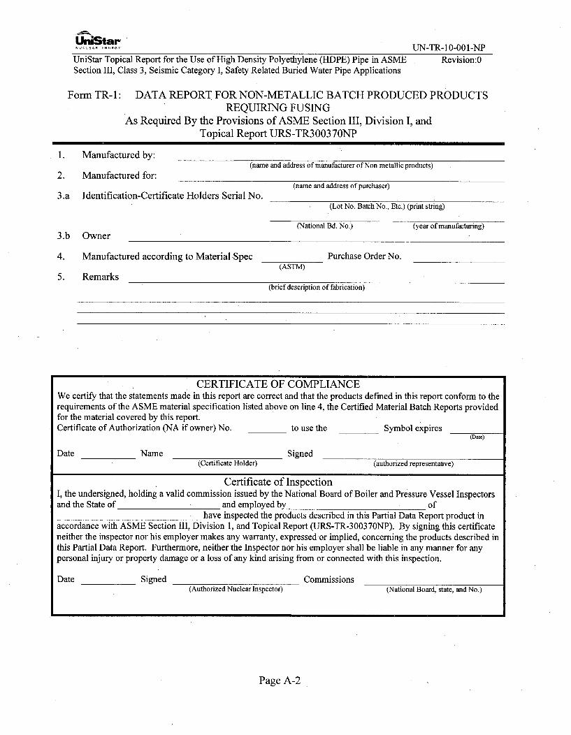
UniStar NNUCLEAR F.CR. Y UN-TR-10-001-NP
UniStar Topical Report for the Use of High Density Polyethylene (HDPE) Pipe in ASME Revision:0Section III, Class 3, Seismic Category I, Safety Related Buried Water Pipe Applications
Form TR-l: DATA REPORT FOR NON-METALLIC BATCH PRODUCED PRODUCTSREQUIRING FUSING
As Required By the Provisions of ASME Section III, Division I, andTopical Report URS-TR30037ONP
1. Manufactured by:(name and address of manufacturer of Non metallic products)
2. Manufactured for:(name and address of purchaser)
3.a Identification-Certificate Holders Serial No.(Lot No. Batch No., Etc.) (print string)
(National Bd. No.) (year of manufacturing)
3.b Owner
4. Manufactured according to Material Spec Purchase Order No.(ASTM)
5. Remarks(brief description of fabrication)
CERTIFICATE OF COMPLIANCEWe certify that the statements made in this report are correct and that the products defined in this report conform to therequirements of the ASME material specification listed above on line 4, the Certified Material Batch Reports providedfor the material covered by this report.Certificate of Authorization (NA if owner) No. to use the Symbol expires
(Date)
Date Name Signed(Certificate Holder) (authorized representalive)
Certificate of InspectionI, the undersigned, holding a valid commission issued by the National Board of Boiler and Pressure Vessel Inspectorsand the State of and employed by of
have inspected the products described in this Partial Data Report product inaccordance with ASME Section III, Division 1, and Topical Report (URS-TR-300370NP). By signing this certificateneither the inspector nor his employer makes any warranty, expressedor implied, concerning the products described inthis Partial Data Report. Furthermore, neither the Inspector nor his employer shall be liable in any manner for anypersonal injury or property damage or a loss of any kind arising from or connected with this inspection.
Date Signed Commissions(Authorized Nuclear Inspector) (National Board, state, and No.)
Page A-2
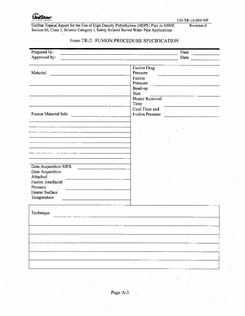
Un•Star"NUVC L EAAfKfR NEG Y UN-TR- 10-001-NPUniStar Topical Report for the Use of High Density Polyethylene (HDPE) Pipe in ASMESection 1II, Class 3, Seismic Category I, Safety Related Buried Water Pipe Applications
Revision:0
Form TR-2: FUSION PROCEDURE SPECIFICATION
Prepared by: DateApproved by: Date
Fusion DragMaterial Pressure
FusionPressureBead-upSizeHeater RemovalTimeCool Time and
Fusion Material Info Fusion Pressure
Data Acquisition MFRData AcquisitionAttachedFusion InterfacialPressureHeater SurfaceTemperature
Technique
Page A-3

'pl
NUnStarUN-TR- 10-001-NP
Revision:0UniStar Topical Report for the Use of High Density Polyethylene (HDPE) Pipe, in ASMESection III, Class 3, Seismic Category I, Safety Related Buried Water Pipe Applications
Form TR-3: FUSION MACHINE OPERATOR PERFORMANCE QUALIFICATION (FPQ)TEST FORM
Operators Name
Payroll Number
Stamp ID
Lab Test Number
Test: Qualification Re-qualification
Fusion Machine Manufacturer
Fusion MachinePipe Size Range
TestPosition
Material Specification to
Fusion SpecificationProcedure
Pipe Size Pipe DR
NDE RequirementsVisual
Free BandTest
VisualResults
Free BandTest Results
Data Acquisition Record Review Results
Test Conducted By
We certify that the statements in this record are correct and that the fused joints are prepared inaccordance with the requirements of Topical Report (URS-TR-30037ONP)
Signed By Date
Page A-4
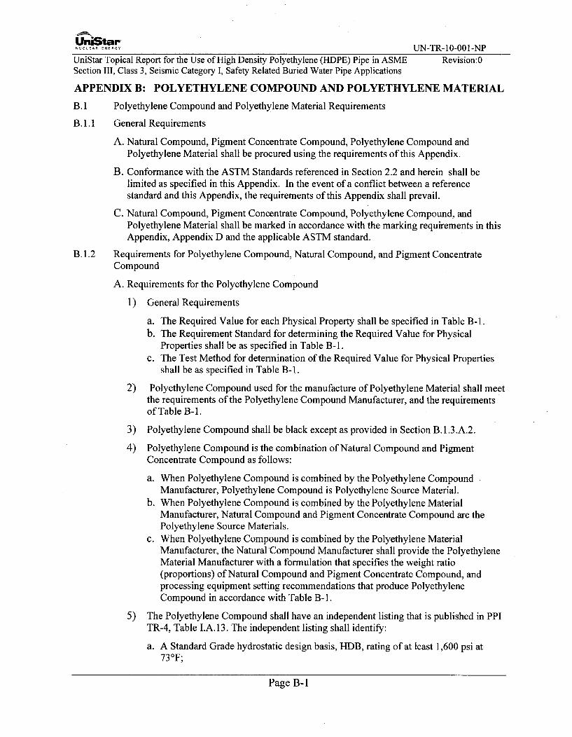
UniStarNUCLEAR ENERGY UN-TR-10-001-NPUniStar Topical Report for the Use of High Density Polyethylene (HDPE) Pipe in ASME Revision:0Section III, Class 3, Seismic Category I, Safety Related Buried Water Pipe Applications
APPENDIX B: POLYETHYLENE COMPOUND AND POLYETHYLENE MATERIAL
B. 1 Polyethylene Compound and Polyethylene Material Requirements
B. 1.1 General Requirements
A. Natural Compound, Pigment Concentrate Compound, Polyethylene Compound andPolyethylene Material shall be procured using the requirements of this Appendix.
B. Conformance with the ASTM Standards referenced in Section 2.2 and herein shall belimited as specified in this Appendix. In the event of a conflict between a referencestandard and this Appendix, the requirements of this Appendix shall prevail.
C. Natural Compound, Pigment Concentrate Compound, Polyethylene Compound, andPolyethylene Material shall be marked in accordance with the marking requirements in thisAppendix, Appendix D and the applicable ASTM standard.
B. 1.2 Requirements for Polyethylene Compound, Natural Compound, and Pigment ConcentrateCompound
A. Requirements for the Polyethylene Compound
1) General Requirements
a. The Required Value for each Physical Property shall be specified in Table B-1.b. The Requirement Standard for determining the Required Value for Physical
Properties shall be as specified in Table B-1.c. The Test Method for determination of the Required Value for Physical Properties
shall be as specified in Table B-1.
2) Polyethylene Compound used for the manufacture of Polyethylene Material shall meetthe requirements of the Polyethylene Compound Manufacturer, and the requirementsof Table B-1.
3) Polyethylene Compound shall be black except as provided in Section B.1.3.A.2.
4) Polyethylene Compound is the combination of Natural Compound and PigmentConcentrate Compound as follows:
a. When Polyethylene Compound is combined by the Polyethylene CompoundManufacturer, Polyethylene Compound is Polyethylene Source Material.
b. When Polyethylene Compound is combined by the Polyethylene MaterialManufacturer, Natural Compound and Pigment Concentrate Compound are thePolyethylene Source Materials.
c. When Polyethylene Compound is combined by the Polyethylene MaterialManufacturer, the Natural Compound Manufacturer shall provide the PolyethyleneMaterial Manufacturer with a formulation that specifies the weight ratio(proportions) of Natural Compound and Pigment Concentrate Compound, andprocessing equipment setting recommendations that produce PolyethyleneCompound in accordance with Table B-1.
5) The Polyethylene Compound shall have an independent listing that is published in PPITR-4, Table I.A. 13. The independent listing shall identify:
a. A Standard Grade hydrostatic design basis, H1DB, rating of at least 1,600 psi at73°F;
Page B-1
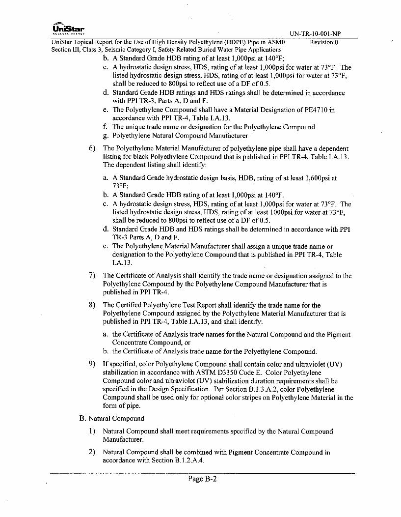
UniStar-NCLEA ERGY UN-TR- 10-001-NP
UniStar Topical Report for the Use of High Density Polyethylene (HDPE) Pipe in ASME Revision:0Section III, Class 3, Seismic Category I, Safety Related Buried Water Pipe Applications
b. A Standard Grade HDB rating of at least 1,000psi at 1407F;c. A hydrostatic design stress, HDS, rating of at least 1,000psi for water at 737F. The
listed hydrostatic design stress, HDS, rating of at least 1,000psi for water at 73°F,shall be reduced to 800psi to reflect use of a DF of 0.5.
d. Standard Grade HDB ratings and HDS ratings shall be determined in accordancewith PPI TR-3, Parts A, D and F.
e. The Polyethylene Compound shall have a Material Designation of PE4710 inaccordance with PPI TR-4, Table I.A. 13.
f. The unique trade name or designation for the Polyethylene Compound.g. Polyethylene Natural Compound Manufacturer
6) The Polyethylene Material Manufacturer of polyethylene pipe shall have a dependentlisting for black Polyethylene Compound that is published in PPI TR-4, Table I.A. 13.The dependent listing shall identify:
a. A Standard Grade hydrostatic design basis, HDB, rating of at least 1,600psi at73°F;
b. A Standard Grade HDB rating of at least 1,000psi at 140'F.c. A hydrostatic design stress, HDS, rating of at least 1,000psi for water at 737F. The
listed hydrostatic design stress, HDS, rating of at least 1000psi for water at 73°F,shall be reduced to 800psi to reflect use of a DF of 0.5.
d. Standard Grade HDB and HDS ratings shall be determined in accordance with PPITR-3 Parts A, D and F.
e. The Polyethylene Material Manufacturer shall assign a unique trade name ordesignation to the Polyethylene Compound that is published in PPI TR-4, TableI.A.13.
7) The Certificate of Analysis shall identify the trade name or designation assigned to thePolyethylene Compound by the Polyethylene Compound Manufacturer that ispublished in PPI TR-4.
8) The Certified Polyethylene Test Report shall identify the trade name for thePolyethylene Compound assigned by the Polyethylene Material Manufacturer that ispublished in PPI TR-4, Table I.A. 13, and shall identify:
a. the Certificate of Analysis trade names for the Natural Compound and the PigmentConcentrate Compound, or
b. the Certificate of Analysis trade name for the Polyethylene Compound.
9) If specified, color Polyethylene Compound shall contain color and ultraviolet (UV)stabilization in accordance with ASTM D3350 Code E. Color PolyethyleneCompound color and ultraviolet (UV) stabilization duration requirements shall bespecified in the Design Specification. Per Section B. 1.3.A.2, color PolyethyleneCompound shall be used only for optional color stripes on Polyethylene Material in theform of pipe.
B. Natural Compound
1) Natural Compound shall meet requirements specified by the Natural CompoundManufacturer.
2) Natural Compound shall be combined with Pigment Concentrate Compound inaccordance with Section B. 1.2.A.4.
Page B-2

U -niStar" UN-TR-10-001-NP
UniStar Topical Report for the Use of High Density Polyethylene (HDPE) Pipe in ASME Revision:0Section III, Class 3, Seismic Category I, Safety Related Buried Water Pipe Applications
3) The Natural Compound Manufacturer shall assign a unique trade name or designationto the Natural Compound.
C. Pigment Concentrate Compound
1) Black Pigment Concentrate Compound shall meet requirements specified by theNatural Compound Manufacturer.
2) Black Pigment Concentrate Compound shall be combined with Natural Compound inaccordance with Section B. 1.2.A.4.
3) The Pigment Concentrate Compound Manufacturer shall assign a unique trade name ordesignation to the Pigment Concentrate Compound.
4) Color Pigment Concentrate Compound shall be in accordance with Section B. 1.3.A.2
and Section B.1.3.A.2.b.
B. 1.3 Polyethylene Material
A. Polyethylene Material- Pipe
1) PE Material in the form of pipe shall be manufactured in accordance with this TopicalReport and ASTM D3035 for sizes below 3-inch nominal outside diameter or ASTMF714 for sizes 3- inch nominal outside diameter and larger. Elevated temperaturesustained pressure test per ASTM D3035 of ASTM F714 shall be successfullycompleted twice annually.
2) Pipe shall be black and shall be manufactured by Plastic Extrusion. With theexception of optional color stripes, black pipe shall contain 2 to 3% carbon black thatis well dispersed through the pipe wall when samples taken from pipe are tested perASTM D1603 or ASTM D4218.
a. Optional color stripes that are coextruded into the pipe outside surface duringplastic extrusion are acceptable. The depth of optional color stripes into the pipeoutside surface shall not exceed 10% of the tfab mim minimum wall thickness requiredfor the pipe design stress. Color stripes shall not project above the pipe outsidesurface and shall not be covered in whole or in part by black pipe material.
b. Where Natural Compound and Pigment Concentrate Compound are combined bythe Polyethylene Material Manufacturer, the Polyethylene Material Manufacturershall use the same Natural Compound with black Pigment Concentrate Compoundand with color Pigment Concentrate Compound if optional color stripes arecoextruded into the pipe outside surface.
c. Where black Polyethylene Compound and color Polyethylene Compound are usedto extrude pipe with optional color stripes, coextruded into the outside surface, theblack Polyethylene Compound and color Polyethylene Compound shall have beencombined using the same Natural Compound.
3) Pipe print line marking shall be applied during plastic extrusion using heatedindentation.
4) Prior to shipment of the pipe, the purchaser may specify any testing requirements forthe fusibility of the material per Section 10.3.4.
B. Polyethylene Material - Flange Adapter
This section provides requirements for flange adapters.
Page B-3

UniStar............. UN-TR-10-001-NP
UniStar Topical Report for the Use of High Density Polyethylene (HDPE) Pipe in ASME Revision:0Section III, Class 3, Seismic Category I, Safety Related Buried Water Pipe Applications
Prior to shipment of the pipe, the purchaser may specify any testing requirements for thefusibility of the material per Section 10.3.4.
1) Polyethylene Material - Machined Flange Adapter
The Polyethylene Material used to fabricate flange adapters that are machined frompipe shall meet the requirements of B. 1.3.A.
2) Polyethylene Material - Molded Flange Adapter
This section provides the requirements for molded-to-size flange adapters and moldedflange adapters that are machined to size.
The Polyethylene Compound used to manufacture molded flange adapters shall meetthe requirements of B. 1.2.A and shall be manufactured in accordance with this TopicalReport.
B.2 Quality Assurance General Requirements
The Polyethylene Source Material Manufacturer and the Polyethylene Manufacturer shall haveQuality Programs in compliance with NCA-3970 (2010 edition or later) or Appendix D of thisTopical Report.
It is not the intent of this paragraph to require that individual lots of Polyethylene SourceMaterial be qualified per B. 1.2 because several of the B. 1.2 qualification requirements aredetermined by tests of numerous samples for up to 10,000 hours (11.4 years) duration.However, the Polyethylene Source Material Manufacturer shall assure that B. 1.2 PolyethyleneCompound Qualification requirements are met through its Quality Program. In general, theminimum quality testing requirements in this Appendix are intended to provide traceability andto assure Polyethylene Material in accordance with the design requirements of this TopicalReport.
B.2.1 Certificate of Analysis
The following contains requirements for Certificate of Analysis.
A. PE Compound Certificate of Analysis
1) Polyethylene Compound shall be qualified per Table B-1.
2) The Polyethylene Compound Manufacturer shall test Polyethylene Compound inaccordance with'Table B-2 and shall provide a Certificate of Analysis (C of A) to thepurchaser of the lot.
3) The Certificate of Analysis shall provide the following information:
a. Certified test results in accordance with Table B-2;b. The name of the Polyethylene Compound Manufacturer;c. The manufacturing location;d. A code or number that is unique and-specific to the lot;e. The Polyethylene Compound Manufacturer's trade name for the Polyethylene
Compound as published in PPI TR-4;f. The shipping method or type of container(s) for the lot such as railcar or boxes and
additional information such as a railcar number if shipped by rail or the name of thecommercial carrier and number of boxes if shipped by commercial carrier;
g. The lot quantity of Polyethylene Compound in pounds;h. The date of shipment;
Page B-4

UniStarNUCLEAR .. ENGY UN-TR- 10-001-NP
UniStar Topical Report for the Use of High Density Polyethylene (HDPE) Pipe in ASME Revision:0Section III, Class 3, Seismic Category I, Safety Related Buried Water Pipe Applications
i. Other information that identifies the purchaser (customer), purchaser order,purchaser contact, purchaser delivery location, and contact information for thePolyethylene Compound Manufacturer.
B. Natural Compound Certificate of Analysis
1) The Natural. Compound Manufacturer shall test Natural Compound in accordance withTable B-3. The Natural Compound Manufacturer shall provide a Certificate ofAnalysis to the purchaser of the lot.
2) The Certificate of Analysis shall provide the following information:
a. Certified test results in accordance with Table B-3;b. The name of the Natural Compound Manufacturer;c. The manufacturing location;d. A code or number that is unique and specific to the lot;e. The Natural Compound Manufacturer's trade name for the Natural Compound;f. The shipping method or type of container(s) for the lot such as railcar or boxes and
additional information such as a railcar number if shipped by rail or the name of thecommercial carrier and number of boxes if shipped by commercial carrier;
g. The lot quantity of Natural Compound in pounds;h. The date of shipment;i. Other information that identifies the purchaser (customer), purchaser order,
purchaser contact, delivery location, and contact information for the NaturalCompound Manufacturer.
C. Pigment Concentrate Compound Certificate of Analysis
1) The Pigment Concentrate Compound Manufacturer shall test Pigment ConcentrateCompound in accordance with Table B-4. The Pigment Concentrate CompoundManufacturer shall provide a Certificate of Analysis to the purchaser of the lot.
2) The Certificate of Analysis shall provide the following information:
a. Certified test results in accordance with Table B-4;b. The name of the Pigment Concentrate Compound Manufacturer;c. The manufacturing location;d. A code or number that is unique and specific to the lot;e. The name of the Pigment Concentrate Compound Manufacturer's trade name for
the Pigment Concentrate Compound;f. The shipping method or type of container(s) for the lot such as railcar or boxes and
additional information such as a railcar number if shipped by rail or the name of thecommercial carrier and number of boxes if shipped by commercial carrier;
g. The lot quantity of Pigment Concentrate Compound in pounds;h. The date of shipment;i. Other information that identifies the purchaser (customer), purchaser order,
purchaser contact, delivery location, and contact information for the PigmentConcentrate Compound Manufacturer.
B.2.2 Certified Polyethylene TestReport for Polyethylene Material - Pipe
A. The Polyethylene Material Manufacturer of pipe shall verify Certificate of Analysis valuesby testing a sample from the Polyethylene Source Material lot in accordance with Table
Page B-5

UniStar-CLEAR..NERGY UN-TR-10-001-NP
UniStar Topical Report for the Use of High Density Polyethylene (HDPE) Pipe in ASME Revision:0Section III, Class 3, Seismic Category I, Safety Related Buried Water Pipe Applications
B-5. The Polyethylene Source Material lot shall not be used when testing does not verifyCertificate of Analysis values.
B. The PE Material Manufacturer of pipe shall test pipe in accordance with Table B-6 andshall provide a Certified Polyethylene Test Report (CPTR) to the purchaser.
C. For each lot, the CPTR shall provide the following information:
1) Certified test results for the lot in accordance with Table B-6;
2) The name of the Polyethylene Material Manufacturer;
3) The manufacturing location;
4) A code or number that is unique and specific to the lot;
5) The ASTM standard for pipe manufacture;
6) The specification for the Polyethylene Compound, e.g., this Topical Report,Mandatory Appendix B;
7) The shipping method and the name of the commercial carrier;
8) The lot quantity in feet;
9) The date of shipment;
10) Other information that identifies the purchaser (customer), purchaser order, purchasercontact, delivery location, and contact information for the Polyethylene MaterialManufacturer.
11) A certification that the Polyethylene Material was made from only virgin polyethylenematerial and that no scrap or regrind material was used (see Appendix D NCA-3974.3).
B.2.3 Certified Polyethylene Test Report for Polyethylene Material - Molded Flange Adapters
A. The Polyethylene Material Manufacturer of molded flange adapters shall verify Certificateof Analysis values by testing a sample from the Polyethylene Source Material lot inaccordance with Table B-5. The Polyethylene Source Material lot shall not be used whentesting does not verify Certificate of Analysis values.
B. The PE Material Manufacturer of pipe shall test pipe in accordance with Table B-6 andshall provide a Certified Polyethylene Test Report (CPTR) to the purchaser.
C. For each lot, the CPTR shall provide the following information:
1) Certified test results for the lot in accordance with Table B-6;
2) The name of the Polyethylene Material Manufacturer;
3) The manufacturing location;
4) A code or number that is unique and specific to the lot;
5) The ASTM standard for molded fitting / flange adapter manufacture;
6) The specification for the Polyethylene Compound, e.g. this Topical Report MandatoryAppendix B;
7) The shipping method and the name of the commercial carrier;
Page B-6

UniStar-NUCLEAR.....R.. UN-TR-10-001-NP
UniStar Topical Report for the Use of High Density Polyethylene (HDPE) Pipe in ASME Revision:0Section 1II, Class 3, Seismic Category I, Safety Related Buried Water Pipe Applications
8) The lot quantity in pieces;
9) The date of shipment;
10) Other information that identifies the purchaser (customer), purchaser order, purchasercontact, delivery location, and contact information for the Polyethylene MaterialManufacturer.
11) A certification that the Polyethylene Material was made from only virgin polyethylenematerial and that no scrap or regrind material was used (see NCA-3974.3).
Page B-7

UnStar"NUCLEAR ENERGY UN-TR-10-001-NP
UniStar Topical Report for the Use of High Density Polyethylene (HDPE) Pipe in ASMESection III, Class 3, Seismic Category I, Safety Related Buried Water Pipe Applications
Revision:0
Table B-i: Compound Physical Properties
No. Property, units Required Value Requirement Test MethodStandard
a) 0.956 to 0.968 w/2-3% ASTM D1505 or
Density, g/cm3 carbon black ASTM D3350 ASTM D792 or ASTMb) 0.947 to 0.955 w/o carbon D4883black or pigment
Polyethylene2 High Load Melt Flow 4 to 20 Compound ASTM D1238,
Rate, g/10 min Manufacturer Quality Condition 190 / 21.6Program
ASTM D3350 and ASTM D4218 or3 Carbon Black, % 2 to 3 TbeBlAT 10Table B-1I ASTM D1603
Slow Crack Growth > 2000 ASTM D3350 and ASTM F1473Resistance, hrs Table B-1
5 Thermal Stability, OF > 428 ASTM D3350 ASTM D33506 Tensile Strength at > 3500 ASTM D3350 ASTM D638, Type IV
Yield, psi at 2in/min7 Tensile Elongation at > 500 ASTM D3350 ASTM D638, Type IV
Break, % at 2in/minASTM D2837, PPI TR- ASTM D2837, PPI TR-
3 and PPI TR-4 3 and PPI TR-4ASTM D2837, PPI TR- ASTM D2837, PPI TR-
3 and PPI TR-4 3 and PPI TR-410 HDS for water at 1000 ASTM D2837, PPI TR- ASTM D2837, PPI TR-
73°F, psi 3 and PPI TR-4 3 and PPI TR-4Thermoplastic Pipe
11 Material Designation PE 4710 Listed in PPI TR-4 N/ACode
Page B-8

UnULtarNUN-TR- 10-001-NP
UniStar Topical Report for the Use of High Density Polyethylene (HDPE) Pipe in ASMESection III, Class 3, Seismic Category I, Safety Related Buried Water Pipe Applications
Revision:0
Table B-2: Minimum Quality Test Requirements for Polyethylene Compound
No. Test Test Standard Test Frequency Test Timing C of A ReportsTest Result
High Load Melt Flow
1 Rate, ASTM D1238 Once per lotCondition 190/21.6, and Table B-i
g/10 minASTM D792 or
2 DesityASTM D1505 or2 Density ASTM D4883 Once per lot Before lot shipment Yes
and Table B-1Tensile strength at ASTM D638
3 yield and tensile and Table B- 1 Once per lot Before lot shipment Yeselongation
4 ThrmalStablity ASTM D33504 Thermal Stability and Table B-i Once per lot Before lot shipment Yes
ASTM D1603 or5 Carbon black content ASTM D4218 Once per lot Before lot shipment Yes
and Table B-i
Table B-3: Minimum Quality Test Requirements for Natural Compound
No. Test Test Standard Test Frequency Test Timing C of A ReportsTest Result
High Load Melt Flow
1 Rate, ASTM D1238 Once per lot N/A YesCondition 190/21.6,g/10 min
ASTM D792 orASTM D1505 or
2 Density ASTM D4883 Once per lot Before lot shipment Yes
and Table B-1Tensile strength at
3 yield and tensile ASTM D638 Once per lot Before lot shipment Yeselongation
4 Thermal Stability ASTM D3350 Once per lot Before lot shipment Yes
Page B-9
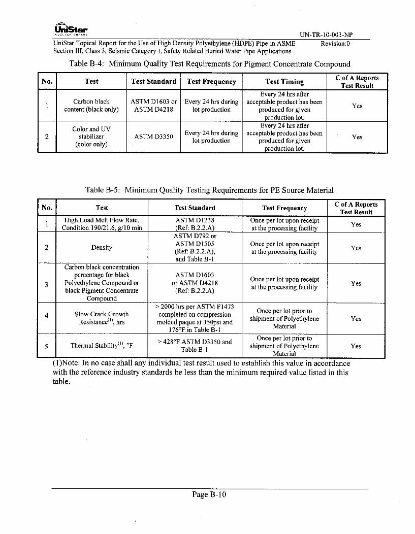
UniStai"NUCLEAR ENERGY UN-TR- 10-001-NPUniStar Topical Report for the Use of High Density Polyethylene (HDPE) Pipe in ASMESection III, Class 3, Seismic Category I, Safety Related Buried Water Pipe Applications
Revision:0
Table B-4: Minimum Quality Test Requirements for Pigment Concentrate Compound
No. Test Test Standard Test Frequency Test Timing C of A Reports_Test Result
Every 24 hrs afterCarbon black ASTM D1603 or Every 24 hrs during acceptable product has been Yescontent (black only) ASTM D4218 lot production produced for given
production lot.Color and UV Every 24 hrs after
2 stabilizer ASTM D3350 Every 24 hrs during acceptable product has been Yes(color only) lot production produced for given
L I_ I production lot.
Table B-5: Minimum Quality Testing Requirements for PE Source Material
No. Test Test Standard Test Frequency C of A ReportsTest Result
I High Load Melt Flow Rate, ASTM Dl1238 Once per lot upon receipt YesCondition 190/21.6, g/10 min (Ref. B.2.2.A) at the processing facility
ASTM D792 or
2 Density ASTM D1505 Once per lot upon receipt Yes(Ref: B.2.2.A), at the processing facilityand Table B-1
Carbon black concentrationpercentage for black ASTM D1603 Once per lot upon receipt
3 Polyethylene Compound or or ASTM D4218 Once proessin faceit Yesblack Pigment Concentrate (Ref: B.2.2.A) at the processing facility
Compound> 2000 hrs per ASTM F1473 Once per lot prior to
4 Slow Crack Growth completed on compressionResistance('), hrs molded paque at 350psi and shipment of Polyethylene Yes
176°F in Table B-1
> 4287F ASTM D3350 and Once per lot prior to5 Thermal Stability('), OF Table B-1 shipment of Polyethylene Yes
I I_ Material
(1)Note: In no case shall any individual test result used to establish this value in accordancewith the reference industry standards be less than the minimum required value listed in thistable.
Page B- 10

UniStarNUCLEAR ENERGY UN-TR- 10-001-NP
UniStar Topical Report for the Use of High Density Polyethylene (HDPE) Pipe in ASMESection III, Class 3, Seismic Category I, Safety Related Buried Water Pipe Applications
Revision:0
Table B-6: Minimum Quality Testing Requirements for PE Material - Pipe
No. Test Test Standard Test Frequency C of A ReportsTest Result
ASTM D3035 for < 3" IPS Hourly or once per length,1 Workmanship ASTM F714 for < 3" IPS whichever is less frequent YesASTM F714 for Ž: 3" f'S during ongoing production
ASTM D3035 for < 3Y IPS Hourly or once per length,2 Outside Diameter ASTM F714 for > 3" IPS whichever is less frequent Yesduring ongoing production
3 Toe-In ASTM D3035 for < 3" IPS Once per shift during ongoing YesASTM F714 for Ž_ 3" IPS production
ASTM D3035 for < 3" IPS Hourly or once per length,4 Wall thickness ASTM F714 for > 3" IPS whichever is less frequent Yes
during ongoing production
ASTM D3035 for < 3" IS At the beginning of production5 Short term strength ASTM F714 for > 3" IPS and weekly thereafter during Yesongoing production
At the beginning of production6 Carbon black content B.1.3.A.2 and daily thereafter during Yes
I ongoing production
Page B- I1

UniStar-NUCLEA.R ENERG UN-TR-10-001-NP
UniStar Topical Report for the Use of High Density Polyethylene (HDPE) Pipe in ASME Revision:0Section III, Class 3, Seismic Category I, Safety Related Buried Water Pipe Applications
APPENDIX C: Rate Process Method for HDB and Design Life
C. 1 -Objective
The purpose of this appendix is to support the HDPE Topical Report for the U.S. EPRTMwhich plans to use HDPE pipe in a Safety Class 3 service water application. The plasticpipe industry currently qualifies PE4710, for 50 years up to 140'F, however the US EPRTMservice water system is being designed for a temperature excursion up to 160'F for aperiod of 30 days, and a design life of 60 years. This appendix is intended to prove thatthe pipe can be designed for 140'F and still safely operate with a 30 day temperatureexcursion up to 160'F, for a 60 year plant design life. This appendix also establishes the50 year and 60 year LTHSs for temperatures up to 160 0F.
C.2 Design Criteria
The following are the design parameters of the HDPE piping system:
Design Temperature: 140OF
Design Pressure: 200psig
Design Life: 60 years
HDS @ 140TF = 500psi (DF = 0.50)
Pipe wall DR = 2(HDS/P) +1 = 2(500/200) + 1 = 6
Normal.Operating Parameters (see C.4.2)
Transient Parameters (see C.4.3)
C.3 Methodology
The PPI Hydrostatic Stress Board (HSB) conducted an extensive evaluation of variousmethods for forecasting the effective long-term performance of polyethylene (PE)thermoplastic piping materials. Basically, these methods require elevated temperaturesustained pressure testing of pipe where the type of failure is the slit or brittle-like mode.
As a result of this study, HSB determined that the three-coefficient Rate Process Method(RPM) equation provided the best correlation between calculated long-term performanceprojections and known field performance of several PE piping materials. It also had thebest probability for extrapolation of data based on the statistical "lack of fit" test.
The Rate Process Method (RPM), which was developed out of this study, was incorporatedinto ASTM D2837. ASTM D2837 also includes a "validation" requirement for PE pipingmaterials HDB. The RPM method can be used as a way to create a math model for theestablished regression curves, even though it may not be suitable for testing purposes. Theregression curves are linear on a logarithmic grid, with the curves for each temperatureparallel to one another. These curves can be used with the RPM to predict materialperformance for stress and temperature values that lie between the curves, including theRPM extrapolation of these curves beyond 60 years. EPRI Report 1013549, updatedSeptember 2006, Appendix D, uses the RPM to predict the 60 year LTHS for PE 3408 pipe(PE 3408 is not a bimodal high performance PE material).
Using the failure mode data points from the Lyondell Basell Alathon L4904-Blackregression curves, the following equation can be solved for the coefficients A, B and C.
Page C- I

U'niStar-NUCLE.ARENERG UN-TR-10-001-NP
UniStar Topical Report for the Use of High Density Polyethylene (HDPE) Pipe in ASME Revision:0Section III, Class 3, Seismic Category I, Safety Related Buried Water Pipe Applications
Logt = A + B + CLogST T
Where:
t = slit mode failure time, hours
T = absolute temperature, R
S = LTHS, psi (based on a DF of 0.50), the LTHS= hoop stress x 2
This data is used to solve for the coefficients A, B, and C. The coefficients are used tosolve the design life for the normal operating condition and elevated temperatureexcursion.
C.4 Calculations inputs
C.4.1 Data from the Regression Curve
The following data has been taken from the Lyondell Basell Alathon L4904-Blackregression curves:
Data From L4904 Regression CurveTemperature HDB (psi) Time to Failure (hrs)
T1= 73°F S1= 1581.05 tj = 100000T2= 140°F 82= 971.835 t 2 = 100000
T 3= 176 0F S3= 797.775 t 3 = 21900
C.4.2 Normal Operating Parameters for the ESW Make-Up Water at 11 5°C
The following are the normal operating parameters for the ESW System
Temperature: 1 150F (Normal Operating Temp)
Pressure: 80psig (Normal Operating Pressure)
Hoop Stress: 200psi (from hoop stress DR equation)
S = P(DR- 1) = 80psig (6-1)= 200psi2 2
Note d/t = IDR, 36/9=4 (DR=IDR+2=6)
For a Design Factor of 0.5, the LTHS used in the Rate Process Method is two times theoperating hoop stress, 2 x 200psi=400psi.
Page C-2

UniStar-NUCLEA.ENERGY UN-TR- 10-001-NP
UniStar Topical Report for the Use of High Density Polyethylene (HDPE) Pipe in ASME Revision:0Section III, Class 3, Seismic Category I, Safety Related Buried Water Pipe ApplicationsC.4.3 Transient Parameters
The following are the transient parameters for the ESW:
Temperature: 160OF
Hoop Stress: 500psi
Duration: 30 days (U.S. EPRTM temperature excursion duration)
The hoop stress is taken as the hoop stress at the design pressure of 200psig for a DR6 pipewall. For a Design Factor of 0.5, the LTHS used in the Rate Process Method is two timesthe operating hoop stress, 2 x 500psi=1000psi
C.5 Calculation Results
C.5.1 Coefficients from the Rate Process Method
The data from the Lyondell Basell regression curves can be written in the following form:
Log(00,000)=A± + B CxLog(1581.05)73+ 460 73+ 460
Log(100,000) = A + B + CxLog(971.835)140+ 460 140+ 460
Log(21,000) = A + B + Cx Log(797.775)176+ 460 176 +460
Since there are three equations and three unknown variables (A, B, and C), matrices can beused to solve the system of equations.
1 1 log(S,)S+460 T+460 Log(t)A
F= 1 1 log(S 2) D= Log(O2) [F]-'[D]=[H]=T2 +460 T2 +460 Log (1 log(S3)T3+460 T3 +460
The solution to the system of equations yields the following results for the coefficients
used in the Rate Process Method:
Rate ProcessMethod
A= -42.457B= 73419.299
C= -15043.99
Page C-3

UniStarNUCLEAR ENERGY UN-TR-10-001-NP
UniStar Topical Report for the Use of High Density Polyethylene (HDPE) Pipe in ASME Revision:0Section III, Class 3, Seismic Category I, Safety Related Buried Water Pipe Applications
C.5.2 Establishing the 50 year and 60 year LTHSs for Temperatures up to 160'F
This section will establish the Hydrostatic Design Basis, HDB, for HDPE 4710 materialusing the Rate Process Method. The variables which are used in the Rate Process Methodare data points that were already established using other test methods. Using thecoefficients from section C.5.1, the Rate Process Method can be used to extrapolate theregression curve out to 1607F at 100,000 hours (11.4 years).
Log(100,OOOhrs)= -42.457+ 73,419.229-+ -15,043.93 x Log(s)1601F +460 1601F +460
Solving this equation for S, yields an HDB stress of 840.416psi. An HDB of 800psi can beused at 1607F since the calculated value, 840.416psi, is within the range for an 800psiHDB per Table 1 of ASTM D2837.
Using the Rate Process Method again for validation of this 800psi HDB per Table 7 ofASTM D2837, calculate the stress at 176°F for 37,500 hours which yields the followingresult:
Log(37,50hrs) = -42.457 + 73,419.229 - 15,043.93 x Log(S)1761F +460 176 0F +460
where the stress, S, is equal to 779.883 psi. Per Table 7 of ASTM D2837 a stress of779.883psi is greater than the required stress of 705psi to establish and validate an HDB of800psi at 1607F.
Now that the HDB is established for 160'F, The Rate Process Method can be used toextrapolate this 160'F HDB from 100,000 hours (11.4 years) to 438,000 hours and525,600 hours (to derive the 50 year and 60 year LTHSs respectively),
Lo(4380000hr) = -42.457+ 73,419.229 -15,043.93 x Log(s)1601F +460 160°F +460
Log(525,600hrs) = -42.457 + 73,419.229_ - 15,043.93 x Log(s)160'F +460 160'F +460
These equations yield 160'F 50 year and 60 year LTHS stresses of 790.78 psi and 784.86psi respectively.
The Rate Process Method can also be used to extrapolate the 73°F HDB from 100,000hours (11.4 years) to derive the 73°F LTHS at 438,000 hours and at 525,600 hours (50year LTHS and 60 year LTHS respectively),
73,419.229 -15,043.93x Log(S)Log(438,0000hrs) =-42.457+ + -
73 0F +460 73°F +460
Log(525,600hrs)= -42.457 + 73,419.229 +- 15,043.93x Log(S)73 0F +460 73 0F +460
These equations yield 73°F 50 year and 60 year LTHS stresses of 1500.42 psi and 1490.76psi respectively.
Page C-4

UniStar"NUCLEAR ENER•GY UN-TR- 10-001-NPUniStar Topical Report for the Use of High Density Polyethylene (HDPE) Pipe in ASMESection III, Class 3, Seismic Category I, Safety Related Buried Water Pipe ApplicationsC.5.3 Design Life for Normal Operation ESW @ 1 15'F
Revision:0
The following calculation uses the coefficients calculated in Section C.5.1 and the inputsfrom Section C.4.2, to determine the design life at normal operating pressures andtemperatures.
Log (t)=-42.457 +73,419.229 - 15,043.93 x Log(400psi)
1151F +460 1151F +460
Rate Process Method to determine the Design Life of ESW @ 1 15°F
A = -42.457 Section C.5.1
B = 73419.229 Section C.5.1
C = -15043.93 Section C.5.1
T =U.S. EPRTM (COLA) FSAR Rev.2115 OF Section 9.2.1
S = 400 psi LTHS from Section C.4.2
t = 1.410x10 17 hrs RPM to solve for hours
1.61x10¹³ years Design Life for 115°F @ 400psi
C.5.4 Design Life for Temperature Excursion
The following calculation uses the coefficients calculated in Section C.5.1 and the inputsfrom Section C.4.3, to determine the design life at the transient temperatures.
Log(t) = -42.457 + 73,419.229 + - 15,043.93 x Log(1O00Opsi)160°F +460 160'F + 460
Rate Process Method to determine the service life @ 160'F
A = -42.457 Section C.5.1
B = 73419.229 Section C.5.1
C = -15043.93 Section C.5.1
T = 160 OF 30 Day temperature excursion
S = 1000 psi LTHS from Section C.4.3
t = 1,469.745 hrs RPM to solve for hours
61.208 Days Design Life for 160'F @ 1000psi
Page C-5

U'nLtar-.. LI......... UN-TR-10-001-NP
UniStar Topical Report for the Use of High Density Polyethylene (HDPE) Pipe in ASME Revision:0Section III, Class 3, Seismic Category I, Safety Related Buried Water Pipe Applications
C.5.5 Design Life Determination
The calculated time to rupture is 61 days at 160'F using the hoop stress for a designtemperature of 140'F (1 000psi). The 30 day duration of the temperature transient uses up½2 of the design life for an event that may occur once in the 60-year plant life during whichthis 160'F design condition exists.
30 Day Event / 61 Day Design Life = V2 of the Design Life Used
As noted above, a pipe wall selected for the design conditions will have a much lowerstress during normal operating conditions, and the pipe's design life for normal operationat 115'F is expected to exceed 1000 years (See Section C.5.3). With ½2 of the design liferemaining for normal operation at I5TF, the design life is 500 plus years, which exceedsthe required 60 year plant life.
V2 x 1000 years (Design Life @ 1150) = 500 years > 60 years required for U.S. EPRTM.
C.6 Conclusions
The Rate Process Method was used to determine the design life of the service water pipethat is designed for 140'F and 200psig, with a 30 day temperature excursion of 160'F.This calculation has shown that the pipe greatly exceeds the required 60 year service lifebased on normal operation parameters and the transient parameters.
C.7 References
C.7.1 PPI TN-16-2008, Rate Process Method for Projecting Performance of PE PipingComponents
C.7.2 ASTM D3350-2006, Standard Specification for PE Plastics Pipe and Fittings PEcompounds
C.7.3 EPRI 1013549-2006, Nondestructive Evaluation: Seismic Design Criteria for PolyethylenePipe Replacement Code Case
C.7.4 ASTM D2837-2008, Standard Test Method for Obtaining Hydrostatic Design Basis forThermoplastic Pipe Materials or Pressure Design Basis for Thermoplastic Pipe Products.
C.7.5 ISO 9080 Regression Analysis per Becetel's Standard Extrapolation Method (SEM)Software, Lyondell Basell
C.7.6 ASTM F714-08, Standard Specification for PE Plastic Pipe (SDR-PR) Based on OutsideDiameter
Page C-6
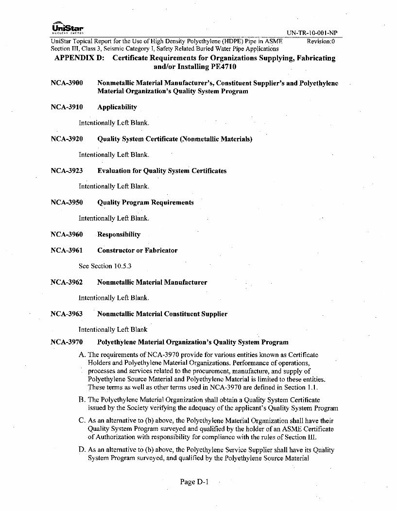
UniStar 1-0 NNUCLEAR........ UN-TR-10-001-NPUniStar Topical Report for the Use of High Density Polyethylene (HDPE) Pipe in ASME Revision:0Section III, Class 3, Seismic Category I, Safety Related Buried Water Pipe ApplicationsAPPENDIX D: Certificate Requirements for Organizations Supplying, Fabricating
and/or Installing PE4710
NCA-3900 Nonmetallic Material Manufacturer's, Constituent Supplier's and PolyethyleneMaterial Organization's Quality System Program
NCA-3910 Applicability
Intentionally Left Blank.
NCA-3920 Quality System Certificate (Nonmetallic Materials)
Intentionally Left Blank.
NCA-3923 Evaluation for Quality System Certificates
Intentionally Left Blank.
NCA-3950 Quality Program Requirements
Intentionally Left Blank.
NCA-3960 Responsibility
NCA-3961 Constructor or Fabricator
See Section 10.5.3
NCA-3962 Nonmetallic Material Manufacturer
Intentionally Left Blank.
NCA-3963 Nonmetallic Material Constituent Supplier
Intentionally Left Blank
NCA-3970 Polyethylene Material Organization's Quality System Program
A. The requirements of NCA-3970 provide for various entities known as CertificateHolders and Polyethylene Material Organizations. Performance of operations,processes and services related to the procurement, manufacture, and supply ofPolyethylene Source Material and Polyethylene Material is limited to these entities.These terms as well as other terms used in NCA-3970 are defined in Section 1.1.
B. The Polyethylene Material Organization shall obtain a Quality System Certificateissued by the Society verifying the adequacy of the applicant's Quality System Program
C. As an alternative to (b) above, the Polyethylene Material Organization shall have theirQuality System Program surveyed and qualified by the holder of an ASME Certificateof Authorization with responsibility for compliance with the rules of Section III.
D. As an alternative to (b) above, the Polyethylene Service Supplier shall have its QualitySystem Program surveyed, and qualified by the Polyethylene Source Material
Page D-1
UnLStar-NUCLEAR.E.ERGY UN-TR- 10-001-NP
UniStar Topical Report for the Use of High Density Polyethylene (HDPE) Pipe in ASME Revision:0Section III, Class 3, Seismic Category I, Safety Related Buried Water Pipe Applications
Manufacturer or Polyethylene Material Manufacturer using the services of thePolyethylene Service Supplier.
E. Subcontracting is restricted as provided in NCA-3973(b)(2).
F. When requirements of NCA-3 800 are invoked, the term "Material Organization" inNCA-3800 shall apply to Polyethylene Material Organization. The term "material" inNCA-3 800 shall apply to Polyethylene Material and Polyethylene Source Material. Theterm "source material" in NCA-3800 is not applicable.
NCA-3971 Responsibility of Polyethylene Material Organizations
Polyethylene Material Organizations shall be responsible for establishing a Quality SystemProgram in accordance with the requirements of NCA-3972, 3973 and 3974, as applicableto the scope of activities performed.
NCA-3971.1 Additional Responsibility of Polyethylene Source Material Manufacturers
The Polyethylene Source Material Manufacturers' Quality System Program shall includethe following, as a minimum:
A. Establishing and maintaining measures for the traceability of Polyethylene SourceMaterial while under its control.
B. Controlling quality during manufacture, including control of testing, examination, andtreatment of Polyethylene Source Material.
C. Evaluation of Polyethylene Service Suppliers for calibration, testing, andnondestructive examination in accordance with the requirements of NCA-3972.3.
D. Preparing Certificates of Analysis.
E. Shipment of Polyethylene Source Material.
NCA-3971.2 Additional Responsibility of the Natural Compound Manufacturer
In addition to the requirements of NCA-3 971.1, the Natural Compound Manufacturer shallbe responsible for:
A. Providing the required data including test results from a sample of PolyethyleneCompound and obtaining a listing for that sample's Material Designation in accordancewith Plastic Pipe Institute standards listed in Table NCA-7100-2.
B. Issuing the "Natural Compound Manufacturing and Testing Procedure."
C. Determining Pigment Concentrate Compound that, when combined with NaturalCompound manufactured by the Natural Compound Manufacturer, shall producePolyethylene Compound that complies with a material specification permitted bySection III. This shall be done by either (1) or (2), below:
1) Providing procedures to the Pigment Concentrate Compound Manufacturer formanufacture of Pigment Concentrate Compound.
2) Testing Pigment Concentrate Compound provided and identified by the PigmentConcentrate Compound Manufacturer with a specific trade name.
Page D-2

UniLar-NUCLEAR.E.ERY UN-TR-10-001-NP
UniStar Topical Report for the Use of High Density Polyethylene (HDPE) Pipe in ASME Revision:0Section III, Class 3, Seismic Category I, Safety Related Buried Water Pipe Applications
D. Providing documentation to the Polyethylene Compound Manufacturer andPolyethylene Material Manufacturer specifying, by trade name, Pigment ConcentrateCompound that shall comply with a material specification permitted by Section IIIwhen combined with the Natural Compound manufactured by the Natural CompoundManufacturer.
E. Certifying that Natural Compound is in compliance with Section III and the "NaturalCompound Manufacturing and Testing Procedure."
NCA-3971.3 Additional Responsibility of the Pigment Concentrate CompoundManufacturer
In addition to the requirements of NCA-3971.1, the Pigment Concentrate Compound
Manufacturer shall be responsible for:
A. Issuing the "Pigment Concentrate Compound Manufacturing and Testing Procedure."
B. Manufacturing Pigment Concentrate Compound that shall comply with a materialspecification permitted by Section III when it is combined with Natural Compoundmanufactured by the Natural Compound Manufacturer. This shall be done by either (1)or (2), below:
1) Manufacture Pigment Concentrate Compound in accordance with proceduresprovided by the Natural Compound Manufacturer.
2) Manufacture Pigment Concentrate Compound that has been identified, by tradename, as acceptable by the Natural Compound Manufacturer.
C. Certifying that Pigment Concentrate Compound is in compliance with Section III andthe "Pigment Concentrate Compound Manufacturing and Testing Procedure."
NCA-3971.4 Additional Responsibility of the Polyethylene Compound Manufacturer
In addition to the requirements of NCA-3971.1, the Polyethylene Compound Manufacturershall be responsible for:
A. Issuing a "Polyethylene Compound Manufacturing and Testing Procedure."
B. Using Pigment Concentrate Compound and Natural Compound to manufacturePolyethylene Compound that complies with Section III and a material specificationpermitted bySection III.
C. Manufacturing and testing Polyethylene Compound in accordance with the"Polyethylene Compound Manufacturing and Testing Procedure."
D. Certifying that Polyethylene Compound is in compliance with Section III, a materialspecification permitted by Section III, and the "Polyethylene Compound Manufacturingand Testing Procedure."
Page D-3

UniStar".UN-TR-10-001-NP
UniStar Topical Report for the Use of High Density Polyethylene (HDPE) Pipe in ASME Revision:0Section III, Class 3, Seismic Category I, Safety Related Buried Water Pipe Applications
NCA-3971.5 Responsibility of Polyethylene Material Manufacturer
The Polyethylene Material Manufacturer's Quality System Program shall include thefollowing, as a minimum:
A. Establishing and maintaining measures for the traceability of Polyethylene SourceMaterial and Polyethylene Material while under its control.
B. Issuing the "Polyethylene Material Manufacturing and Testing Procedure."
C. Manufacturing Polyethylene Material that complies with a material specificationpermitted by Section III. This shall be done by either (1) or (2) below:
1) Manufacturing Polyethylene Material using Pigment Concentrate Compound andNatural Compound as specified by the Natural Compound Manufacturer.
2) Manufacturing Polyethylene Material using Polyethylene Compound as specifiedby the Polyethylene Compound Manufacturer.
D. Manufacturing and testing Polyethylene Material in accordance with Section III, amaterial specification permitted by Section III, and the "Polyethylene MaterialManufacturing and Testing Procedure."
E. Controlling quality during manufacture, including control of testing, examination, andtreatment of Polyethylene Source Material and Polyethylene Material.
F. Evaluation of Polyethylene Service Suppliers for calibration, testing, andnondestructive examination in accordance with the requirements of NCA-3972.3.
G. Preparing Certified Polyethylene Test Reports.
H. Certifying that all Polyethylene Material is in compliance with Section III, a specificmaterial specification permitted by Section III, and the "Polyethylene MaterialManufacturing and Testing Procedure."
I. Shipment of Polyethylene Material.
NCA-3971.6 Responsibility of Polyethylene Material Supplier
The Polyethylene Material Supplier's Quality System Program shall include the following,as a minimum:
A. Establishing and maintaining measures for the traceability of Polyethylene Materialwhile under its control including identification established per NCA-3971.5(a).
B. Shipment of Polyethylene Material.
NCA-3971.7 Responsibility of Polyethylene Service Supplier
The Polyethylene Service Supplier's Quality System Program shall include the following,as a minimum:
A. Establishing and maintaining measures for the traceability of Polyethylene SourceMaterial and Polyethylene Material while under its control.
Page D-4
UniStar-NUCLEAR.......Y UN-TR-10-001-NP
UniStar Topical Report for the Use of High Density Polyethylene (HDPE) Pipe in ASME Revision:0Section III, Class 3, Seismic Category I, Safety Related Buried Water Pipe Applications
B. Controlling quality including control of testing, and examination of PolyethyleneSource Material and Polyethylene Material.
C. Evaluation of Polyethylene Service Suppliers providing calibration, in accordance withthe requirements of NCA-3972.3.
NCA-3972 Evaluation of Quality System
NCA-3972.1 Evaluation by the Society (ASME)
A. The Society will arrange for a survey of the applicant's Quality System Program for thescope of activities at the locations listed on the application. The evaluation will beconducted in accordance with the requirements of NCA-3841.
B. The Quality System Certificate that is issued, for up to a 3-year period, will describeand specify the scope and limits of work and locations for which the applicant isqualified and will be subjected to a planned audit program by the Society
NCA-3972.2 Evaluation by ASME Certificate Holders
A. Except for evaluation of Polyethylene Service Suppliers, evaluation by parties otherthan the Society shall be performed by an ASME Certificate of Authorization Holder.
B. NCA-3842.2 applies except for the following:
1) The reference in NCA-3842.2 (a) to NCA- 3850 is changed to NCA-3972, NCA-3973 and NCA-3974.
2) The NCA-3842.2 (i) allowance of performance assessments in lieu of annualaudits is prohibited.
NCA-3972.3 Evaluation of Polyethylene Service Suppliers by the Polyethylene SourceMaterial Manufacturer or Polyethylene Material Manufacturer
A. Evaluation of Polyethylene Service Suppliers may be performed by Polyethylene
Source Material Manufacturer or Polyethylene Material Manufacturer using the service.
B. NCA-3842.2 applies except for the following:
1) The reference in NCA-3842.2 (a) to NCA- 3850 is changed to NCA-3972, NCA-3973 and NCA-3974.
2) The NCA-3842.2 (i) allowance of performance assessments in lieu of annualaudits is prohibited.
NCA-3972.4 Evaluation of Polyethylene Service Suppliers of Calibration Services by thePolyethylene Service Suppliers
A. Evaluation of Polyethylene Service Suppliers of calibration services may be performed
by Polyethylene Service Suppliers using the calibration service.
B. NCA-3842.2 applies except for the following:
Page D-5
U niStar.NU CLE ARENERGY U N -TR -10-001-N P
UniStar Topical Report for the Use of High Density Polyethylene (HDPE) Pipe in ASMIE Revision:0Section III, Class 3, Seismic Category I, Safety Related Buried Water Pipe Applications
1) The reference in NCA-3842.2 (a) to NCA- 3850 is changed to NCA-3972, NCA-3973 and NCA-3974.
2) The NCA-3842.2 (i) allowance of performance assessments in lieu of annualaudits is prohibited.
NCA-3973 Quality Program Requirements
A. The Polyethylene Material Organization shall establish a Quality System Program forthe control of quality during manufacture or during other work it proposes to perform,and for the traceability of Polyethylene Source Material, and Polyethylene Materialunder its control. The controls used in the Quality System Program shall bedocumented in a Quality System Manual.
B. The Quality System Program shall be planned, documented, implemented, andmaintained in accordance with the requirements of NCA-3850, as applicable to thescope of activities performed except as follows:
1) NCA-3851.2(a)(6), NCA-3855.1(b), NCA- 3855.3 (a) and (b), NCA-3855.5,NCA-3856.3(b) NCA-3856.3(e), NCA-3856.4, and NCA-3857.3 do not apply andthose activities are prohibited. Provisions of NCA-3855.3 (c) shall be limited tocalibration services
2) Any subcontracting shall be to Polyethylene Service Suppliers. Subcontracting isallowed for testing, nondestructive examination and calibration. Subcontracting ofoperations that affect compliance with the procedures, material property, anddesign requirements of Section III is prohibited.
3) Repair is prohibited.
4) When design of Polyethylene Material is within the scope of activities, designcontrols shall comply with the requirements of ASME NQA-1, Quality AssuranceRequirements for Nuclear Facilities, Basic Requirement 3 and Supplement 3 S- 1.The applicable version of NQA-l shall be in accordance with Table NCA-7100-2.
5) Audits shall include a review of the implementation of all elements of the QualitySystem Program at the location of the work and shall be conducted at leastannually.
6) The "approved supplier" mentioned in NCA- 3800 is not applicable and notallowed.
7) Polyethylene Material Organizations are only allowed to qualify PolyethyleneService Suppliers. Polyethylene Service Suppliers are only allowed to qualifyPolyethylene Service Suppliers performing calibration services.
8) Polyethylene Material shall be permanently marked with the following, as aminimum:
a. Polyethylene Material Manufacturer's company name.b. Polyethylene material specification as permitted by Section III.c. Polyethylene Compound designation as listed in Plastics Pipe Institute TR-4
(Table NCA 7100-2).
Page D-6

UniStar UT 00 NNUCLEAR ENERGY UN-TR-1O-0 1-NP
UniStar Topical Report for the Use of High Density Polyethylene (HDPE) Pipe in ASME Revision:0Section III, Class 3, Seismic Category I, Safety Related Buried Water Pipe Applications
d. A lot number defined and described in the Polyethylene MaterialManufacturer's Quality System Manual and the Certified Polyethylene TestReport that identifies the following information:(1) The Polyethylene Source Material(s);(2) The location of manufacture;(3) The production equipment and personnel or shift;(4) The date of manufacture.
e. Markings (a) thru (d) may be abbreviated in trademarks or codes provided thetrademarks or codes are defined and described in the Polyethylene MaterialManufacturer's Quality System Manual and the Certified Polyethylene TestReport or an identified attachment to the Certified Polyethylene Test Report.
9) Identification of Polyethylene Source Material shall be by marking the containersor tags attached to the containers and shall include the following, as a minimum:
a. Polyethylene Material Manufacturer's company name.b. Polyethylene Source Material designation as listed in Plastics Pipe Institute
TR-4 (Table NCA- 7100-2).c. Location of manufacture.d. Lot number identifying the Polyethylene Source Material.e. Markings (b) thru (d) may be abbreviated by a unique code on the shipping
container provided the codes are defined and described in the PolyethyleneMaterial Manufacturer's Quality System Manual and the Certified PolyethyleneTest Report.
10) Certificates of Compliance are not applicable.
11) Welding and heat treatment are not applicable.
NCA-3974 Certification Requirements
NCA-3974.1 Certificates of Analysis
The Polyethylene Source Material Manufacturer shall provide a Certificate of Analysis.
A. The Certificate of Analysis shall include Polyethylene Source Material identification asrequired by NCA-3973(b)(9), actual test and examination results and any other requiredcertifications.
B. A certification shall be included that affirms that contents of the Certificate of Analysisare correct and accurate and that all test results and examinations performed by theorganization and its subcontractors are in compliance with Section III and specifiedrequirements.
C. Required Certificates of Analysis shall be transmitted at the time of shipment.
NCA-3974.2 Certified Polyethylene Test Reports
The Polyethylene Material Manufacturer and Polyethylene Material Supplier shall providea Certified Polyethylene Test Report for Polyethylene Material.
Page D-7

NUC.....N...r UN-TR-10-001-NP
UniStar Topical Report for the Use of High Density Polyethylene (HDPE) Pipe in ASME Revision:0Section III, Class 3, Seismic Category I, Safety Related Buried Water Pipe Applications
A. The Certified polyethylene Test Reports shall include Polyethylene Materialidentification as required by NCA-3973(b)(8), actual test and examination results andany other required certifications.
B. A certification shall be included that affirms that contents of the report are correct andaccurate and that all test results and operations performed by the organization and itssubcontractors are in compliance with the material specification and the specificapplicable requirements of Section III.
C. The Polyethylene Material Manufacturer shall also certify that the PolyethyleneMaterial conforms to the applicable dimensional requirements.
D. The Polyethylene Material Manufacturer and Polyethylene Material Supplier shalltransmit all required Certified Polyethylene Test Reports including Certificates ofAnalysis from the Polyethylene Source Material Manufacturer at the time of shipment.
NCA-3974.3 Additional Certification Requirements
A. The Certified Polyethylene Test Report shall include the actual results of all requiredphysical and mechanical property tests. A certification that the Polyethylene SourceMaterial used were made from virgin polyethylene, not scrap or regrind PolyethyleneMaterial, shall also be included.
B. When required tests or nondestructive examinations are subcontracted, the approvedPolyethylene Service Supplier's certification for the operations performed shall befurnished as an identified attachment to the Certified Polyethylene Certified TestReport.
C. When operations other than tests or nondestructive examinations that requiremaintenance of traceability are subcontracted, these operations and the approvedPolyethylene Service Supplier performing them shall be listed on the CertifiedPolyethylene Test Report, or the approved Polyethylene Service Supplier's certificationfor the operation may be furnished as an attachment to the Certified Polyethylene TestReport. Operations that affect design or properties of the Polyethylene Source Material,and Polyethylene Material shall not be performed by Polyethylene Service Suppliers.
D. Reporting of actual dimensions and visual examination results is required
E. Polyethylene Material identification shall be described in the Certified PolyethyleneTest Report.
NCA-3974.4 Quality System Program Statement
A. When the Polyethylene Material Organization holds a Quality System Certificate, theorganization's Quality System Certificate number and expiration date shall be shownon the Certificate of Analysis and Certified Polyethylene Test Report.
B. When the organization has been qualified by a party other than ASME, theidentification, revision and date of the applicable Quality System Manual shall beshown on the Certificate of Analysis and Certified Polyethylene Test Report.
C. The inclusion of the Quality System Certificate number and expiration date or referenceto identification, revision and date of the applicable Quality System Manual shall be
Page D-8

UniStar"NUCLEAR ENERGY UN-TR-10-001-NP
UniStar Topical Report for the Use of High Density Polyethylene (HDPE) Pipe in ASME Revision:0Section III, Class 3, Seismic Category I, Safety Related Buried Water Pipe Applications
considered the organization's certification that all activities have been performed inaccordance with the applicable requirements of Section III.
NCA-4100 Requirements
NCA-4110 Scope and Applicability
A. This sets forth the requirements for planning, managing, and conducting QualityAssurance Programs for controlling the quality of activities performed under thisSection and the rules governing the evaluation of such Programs prior to the issuance ofcertificates for the construction, fabrication, manufacture, and installation of Class 3items. The Quality Assurance requirements for Metallic Material Organizations for allClasses of construction are provided in NCA-3 800. The Quality Assurancerequirements for Nonmetallic Material Organizations, Polyethylene MaterialOrganizations and Constituent Suppliers for all Classes of construction are provided inNCA-3900. Certificate Holders are advised to consult other regulations for QualityAssurance requirements governing activities beyond the scope of this Section.
B.ýN-Type Certificate Holders shall comply with the Basic Requirements andSupplements of ASME NQA- 1-1994 Edition, Quality Assurance ProgramRequirements for Nuclear Facilities, as modified and supplemented in NCA-4120(b)and NCA-4134.
Page D-9