UN-R94-03 - 国土交通省. "Unladen kerb mass" means the mass of the vehicle in running order,...
86
UN-R94-03 (2016.6.18) Regulation No. 94 Uniform provisions concerning the approval of vehicles with regard to the protection of the occupants in the event of a frontal collision Contents 協定規則第 94 号 前面衝突時の乗員保護に係る車両認可に関する統一規定 目次 Regulation 1. Scope 2. Definitions 3. Application for approval 4. Approval 5. Specifications 6. Instructions for users of vehicles equipped with airbags 7. Modification and extension of approval of the vehicle type 8. Conformity of production 9. Penalties for non-conformity of production 10. Production definitively discontinued 11. Transitional provisions 12. Names and addresses of Technical Services responsible for conducting approval tests, and of Type Approval Authorities 規則 1. 適用範囲 2. 定義 3. 認可申請 4. 認可 5. 仕様 6. エアバッグを装備した場合の使用者への周知方法 7. 車両型式認可の変更及び拡大 8. 生産の適合性 9. 生産の不適合に対する罰則 10. 生産中止 11. 過渡規定 12. 認可試験を担当する技術機関及び行政官庁の名称及び所在地 Annexes 1 Communication 2 Arrangements of approval marks 3 Test procedure 4 Head Performance Criterion (HPC) and 3 ms head acceleration 5 Arrangement and installation of dummies and adjustment of restraint systems 6 Procedure for determining the "H" point and the actual torso angle for seating positions in motor vehicles 附則 附則 1 通知 附則 2 認可マークの配置 附則 3 試験方法 附則 4 頭部性能基準(HPC)及び 3 ms の頭部加速度 附則 5 ダミーの配置及び取り付け並びに拘束装置の調節 附則 6 自動車の着座位置の「H」点と実トルソ角の決定方法
Transcript of UN-R94-03 - 国土交通省. "Unladen kerb mass" means the mass of the vehicle in running order,...
UN-R94-03 (2016.6.18) Regulation No. 94
Uniform provisions concerning the approval of vehicles with regard to the
protection of the occupants in the event of a frontal collision
Contents
協定規則第 94 号
前面衝突時の乗員保護に係る車両認可に関する統一規定
目次
Regulation
1. Scope
2. Definitions
3. Application for approval
4. Approval
5. Specifications
6. Instructions for users of vehicles equipped with airbags
7. Modification and extension of approval of the vehicle type
8. Conformity of production
9. Penalties for non-conformity of production
10. Production definitively discontinued
11. Transitional provisions
12. Names and addresses of Technical Services responsible for conducting
approval tests, and of Type Approval Authorities
規則
1. 適用範囲
2. 定義
3. 認可申請
4. 認可
5. 仕様
6. エアバッグを装備した場合の使用者への周知方法
7. 車両型式認可の変更及び拡大
8. 生産の適合性
9. 生産の不適合に対する罰則
10. 生産中止
11. 過渡規定
12. 認可試験を担当する技術機関及び行政官庁の名称及び所在地
Annexes
1 Communication
2 Arrangements of approval marks
3 Test procedure
4 Head Performance Criterion (HPC) and 3 ms head acceleration
5 Arrangement and installation of dummies and adjustment of restraint systems
6 Procedure for determining the "H" point and the actual torso angle for seating
positions in motor vehicles
附則
附則 1 通知
附則 2 認可マークの配置
附則 3 試験方法
附則 4 頭部性能基準(HPC)及び 3 ms の頭部加速度
附則 5 ダミーの配置及び取り付け並びに拘束装置の調節
附則 6 自動車の着座位置の「H」点と実トルソ角の決定方法
UN-R94-03 (2016.6.18) Appendix 1 - Description of the three dimensional "H" point machine (3-D H
machine)
付録 1−三次元「H」点測定装置の説明(三次元マネキン)1*/
Appendix 2 - Three dimensional reference system 付録 2−三次元座標方式
Appendix 3 - Reference data concerning seating positions 付録 3−着座位置に関する基準データ
7 Test procedure with trolley 附則 7 台車を使った試験手順
Appendix - Equivalence curve - tolerance band for curve deltaV = f(t) 付録−等価曲線−曲線 ΔV = f(t)の公差範囲
8 Technique of measurement in measurement tests: Instrumentation 附則 8 測定試験における測定技術:計装
9 Definition of deformable barrier 附則 9 変形バリヤの定義
10 Certification procedure for the dummy lower leg and foot 附則 10 ダミーの下肢部及び足部の認証手順
11 Test Procedures for the protection of the occupants of vehicles operating on
electrical power from high voltage and electrolyte spillage
附則 11 電力駆動車両の乗員の高電圧及び電解液の漏出からの保護に関する試
験手順
Appendix - Jointed test finger (degree IPXXB) 付録−関節試験指(等級 IPXXB)
1. Scope
This Regulation applies to vehicles of category M11 of a total permissible mass not
exceeding 2.5 tonnes; other vehicles may be approved at the request of the
manufacturer. 1 As defined in the Consolidated Resolution on the Construction of Vehicles
(R.E.3.), document ECE/TRANS/WP.29/78/Rev.2, para. 2
1. 適用範囲
本規則は、最大質量 2.5 t 以下の車両区分 M11の車両に適用する。その他の車両
はメーカーの要求により認可することができる。 1 車両構造統合決議(R.E.3)、文書 ECE/TRANS/WP.29/78/Rev.2、2 項の定義によ
る。
2. Definitions
For the purpose of this Regulation:
2. 定義
本規則の意図するところでは、
2.1. "Protective system" means interior fittings and devices intended to restrain the
occupants and contribute towards ensuring compliance with the requirements set
out in paragraph 5. below.
2.1. 「保護装置」とは、以下の 5 項に定められた要件に適合するものであって、
乗員を保護するための内部部品及び装置をいう。
2.2. "Type of protective system" means a category of protective devices which do 2.2. 「保護装置の型式」とは、下記の基本特性において異なることのない保護

UN-R94-03 (2016.6.18) not differ in such essential respects as:
Their technology;
Their geometry;
Their constituent materials.
装置をいう。
技術、
形状、
構成材料。
2.3. "Vehicle width" means the distance between two planes parallel to the longitudinal median plane (of the vehicle) and touching the vehicle on either side of the said plane but excluding the external devices for indirect vision, side marker lamps, tyre pressure indicators, direction indicator lamps, position lamps, flexible mud-guards and the deflected part of the tyre side-walls immediately above the point of contact with the ground."
2.3. 「車幅」とは、(車両の)左右対称中央面に平行であって、かつ、その平面
の各側で、車両の最も側方にある部分(間接視界装置、側方灯、タイヤ空気圧
計量装置、方向指示器、車幅灯、尾灯、柔軟性のあるマッドガード及び接地点
の真上のタイヤのサイドウォール歪曲部を除く)に接する2つの平面間の距離
をいう。
2.4. "Overlap" means the percentage of the vehicle width directly in line with the
barrier face.
2.4. 「オーバーラップ」とは、バリヤ面と直対する車幅の百分率をいう。
2.5. "Deformable barrier face" means a crushable section mounted on the front of
a rigid block.
2.5. 「デフォーマブルバリヤフェイス」とは、剛性ブロックの前部に取り付け
られた衝撃吸収材をいう。
2.6. "Vehicle type" means a category of power-driven vehicles which do not differ
in such essential respects as:
2.6. 「車両型式」とは、2.6.1 項から 2.6.7 項までに掲げる事項において基本特性
が異なることのない自動車の区分をいう。
2.6.1. The length and width of the vehicle, in so far as they have a negative effect
on the results of the impact test prescribed in this Regulation;
2.6.1.車両の長さ及び幅(本規則が定める衝突試験の結果に不利な影響を及ぼす
場合に限る)。
2.6.2. The structure, dimensions, lines and materials of the part of the vehicle
forward of the transverse plane through the "R" point of the driver's seat, in so far
as they have a negative effect on the results of the impact test prescribed in this
Regulation;
2.6.2.運転者席の「R」点を通る横断面よりも前方の車両部分の構造部、寸法、
形状及び材料(本規則が定める衝突試験の結果に不利な影響を及ぼす場合に限
る)。
2.6.3. The lines and inside dimensions of the passenger compartment and the type
of protective system, in so far as they have a negative effect on the results of the
impact test prescribed in this Regulation;
2.6.3.車室の形状及び内部寸法並びに保護装置の型式(本規則が定める衝突試験
の結果に不利な影響を及ぼす場合に限る)。
UN-R94-03 (2016.6.18) 2.6.4. The siting (front, rear or centre) and the orientation (transversal or
longitudinal) of the engine, in so far as they have a negative effect on the result of
the impact test procedure as prescribed in this Regulation;
2.6.4.原動機の位置(前部、後部又は中央部)及び向き(横又は縦)(本規則が定
める衝突試験手段の結果に不利な影響を及ぼす場合に限る)。
2.6.5. The unladen mass, in so far as there is a negative effect on the result of the
impact test prescribed in this Regulation;
2.6.5.非積載重量(本規則が定める衝突試験の結果に不利な影響を及ぼす場合に
限る)。
2.6.6. The optional arrangements or fittings provided by the manufacturer, in so far
as they have a negative effect on the result of the impact test prescribed in this
Regulation;
2.6.6.メーカーが供給するオプションの装置又は部品(本規則が定める衝突試験
の結果に不利な影響を及ぼす場合に限る)。
2.6.7. The locations of the REESS, in so far as they have a negative effect on the
result of the impact test prescribed in this Regulation.
2.6.7. REESS の位置(本規則が定める衝突試験の結果に不利な影響を及ぼす場合
に限る)。
2.7. Passenger compartment 2.7. 車室
2.7.1. "Passenger compartment with regard to occupant protection" means the
space for occupant accommodation, bounded by the roof, floor, side walls, doors,
outside glazing and front bulkhead and the plane of the rear compartment bulkhead
or the plane of the rear-seat back support;
2.7.1. 「乗員保護に関する車室」とは、ルーフ、フロア、側壁、扉、外側ガラス、
前部隔壁及び後部車室隔壁若しくは後部座席背面サポートの面によって囲まれ
た乗員収容のための空間をいう。
2.7.2. "Passenger compartment for electric safety assessment" means the space for
occupant accommodation, bounded by the roof, floor, side walls, doors, outside
glazing, front bulkhead and rear bulkhead, or rear gate, as well as by the electrical
protection barriers and enclosures provided for protecting the occupants from
direct contact with high voltage live parts.
2.7.2. 「電気安全性試験のための車室」とは、ルーフ、フロア、側壁、扉、外側
ガラス、前部隔壁及び後部隔壁若しくは後部扉によって囲まれ、また動力系の
高電圧活電部への直接接触から乗員を保護するために設けられた電気保護バリ
ヤ及びエンクロージャを境界とする乗員収容のための空間をいう。
2.8. "R point" means a reference point defined for each seat by the manufacturer in
relation to the vehicle's structure, as indicated in Annex 6.
2.8. 「R 点」とは、附則 6 に規定するところにより、メーカーが定める自動車構
造上の各座席位置の基準点をいう。
2.9. "H point" means a reference point determined for each seat by the testing
service responsible for approval, in accordance with the procedure described in
Annex 6.
2.9. 「H 点」とは、附則 6 に規定する手順に従い、認可を行う試験機関が各座
席について決定する基準点をいう。
2.10. "Unladen kerb mass" means the mass of the vehicle in running order, 2.10. 「非積載質量」とは、乗車人員又は積載物品を乗車又は積載せず、かつ燃

UN-R94-03 (2016.6.18) unoccupied and unladen but complete with fuel, coolant, lubricant, tools and a
spare wheel (if these are provided as standard equipment by the vehicle
manufacturer).
料、冷却水、潤滑油、工具及びスペアタイヤを搭載し、走行可能状態の車両質
量をいう(車両メーカーにより標準装備として供給されている場合)。
2.11. "Airbag" means a device installed to supplement safety belts and restraint
systems in power-driven vehicles, i.e. systems which, in the event of a severe
impact affecting the vehicle, automatically deploy a flexible structure intended to
limit, by compression of the gas contained within it, the gravity of the contacts of
one or more parts of the body of an occupant of the vehicle with the interior of the
passenger compartment.
2.11. 「エアバッグ」とは、自動車の座席ベルト及び拘束装置を補助するために
装備される装置をいう。 例えば、車両に激しい衝撃が加わった際に、車両の乗
員の1箇所以上の身体部分と車室内部との接触による危険を抑制するため、柔
軟な構造物を自動的に展開するシステムをいう。
2.12. "Passenger airbag" means an airbag assembly intended to protect
occupant(s) in seats other than the driver's in the event of a frontal collision.
2.12. 「パッセンジャー・エアバッグ」とは、前面衝突時に、運転者席以外の座
席乗員を保護する目的のエアバッグ・アッセンブリをいう。
2.13. "High voltage" means the classification of an electric component or circuit, if
its working voltage is > 60 V and < 1,500 V direct current (DC) or > 30 V and <
1,000 V alternating current (AC) root - mean - square (rms).
2.13. 「高電圧」とは、直流 60Vを超え 1,500V以下又は交流 30V(実効値)
を超え 1,000V(実効値)以下の作動電圧の場合の電気構成部品又は回路の分類
をいう。
2.14. "Rechargeable energy storage system (REESS)" means the rechargeable
energy storage system which provides electrical energy for propulsion.
2.14. 「充電式エネルギー貯蔵システム(REESS)」とは、駆動に係る電力を供給
する充電式エネルギー貯蔵システムをいう。
2.15. "Electrical protection barrier" means the part providing protection against
any direct contact to the high voltage live parts.
2.15. 「電気保護バリヤ」とは、高電圧活電部への直接接触に対する保護のため
に設けられた部分をいう。
2.16. "Electrical power train" means the electrical circuit which includes the
traction motor(s), and may also include the REESS, the electrical energy
conversion system, the electronic converters, the associated wiring harness and
connectors, and the coupling system for charging the REESS.
2.16. 「電動パワートレーン」とは、駆動用電動機を含む電気回路を指し、REESS、
電気エネルギー変換システム、電子式コンバータ、付随する配線ハーネス及び
コネクタ並びに REESS 充電系連結システムを含むこともある。
2.17. "Live parts" means conductive part(s) intended to be electrically energized in
normal use.
2.17. 「活電部」とは、通常の使用時に通電することを目的とした導電部をいう。
2.18. "Exposed conductive part" means the conductive part which can be touched
under the provisions of the protection degree IPXXB and which becomes
2.18. 「露出導電部」とは、保護等級 IPXXB の措置を施した状態で触れること
ができ、絶縁故障時に通電される導電部をいう。これは、工具を使用せずに除
UN-R94-03 (2016.6.18) electrically energized under isolation failure conditions. This includes parts under a
cover that can be removed without using tools.
去できるカバーで覆われている部分も含む。
2.19. "Direct contact" means the contact of persons with high voltage live parts. 2.19. 「直接接触」とは、人体が高電圧活電部に接触することをいう。
2.20. "Indirect contact" means the contact of persons with exposed conductive
parts.
2.20. 「間接接触」とは、人体が露出導電部に接触することをいう。
2.21. "Protection degree IPXXB" means protection from contact with high voltage
live parts provided by either an electrical protection barrier or an enclosure and
tested using a Jointed Test Finger (degree IPXXB) as described in paragraph 4. of
Annex 11,
2.21. 「保護等級 IPXXB」とは、電気保護バリヤ又はエンクロージャのいずれか
により実現される高電圧活電部への接触からの保護をいい、附則 11 の 4 項に規
定された関節試験指(等級 IPXXB)を用いて試験される。
2.22. "Working voltage" means the highest value of an electrical circuit voltage
root-mean-square (rms), specified by the manufacturer, which may occur between
any conductive parts in open circuit conditions or under normal operating
conditions. If the electrical circuit is divided by galvanic isolation, the working
voltage is defined for each divided circuit, respectively.
2.22. 「作動電圧」とは、開回路状態又は通常の作動状態において、あらゆる導
電部の間に発生する可能性がある電気回路の電圧(rms)の最高値であり、メー
カーが定めるものをいう。電気回路が直流電気的絶縁により分割されている場
合、作動電圧は、分割された各回路に対しそれぞれ定められる。
2.23. "Coupling system for charging the rechargeable energy storage system
(REESS)" means the electrical circuit used for charging the REESS from an
external electrical power supply including the vehicle inlet.
2.23. 「充電式エネルギー貯蔵システム(REESS)充電系連結システム」とは、
外部電源から REESS を充電するために使用される電気回路(車両インレットを
含む)をいう。
2.24. "Electrical chassis" means a set made of conductive parts electrically linked
together, whose electrical potential is taken as reference.
2.24. 「電気的シャシ」とは、電気的に互いに接続された導電性の部分の集合体
であって、その電位が基準とみなされるものをいう。
2.25. "Electrical circuit" means an assembly of connected high voltage live parts
which is designed to be electrically energized in normal operation.
2.25. 「電気回路」とは、通常の作動時に電流が流れるよう設計された高電圧活
電部を接続したものの集合体をいう。
2.26. "Electrical energy conversion system" means a system (e.g. fuel cell) that
generates and provides electrical energy for electrical propulsion.
2.26. 「電気エネルギー変換システム」とは、電気的駆動力のために電気エネル
ギーを発生し、これを提供するシステム(例:燃料電池)をいう。
2.27. "Electronic converter" means a device capable of controlling and/or
converting electrical power for electrical propulsion.
2.27. 「電子式コンバータ」とは、電気的駆動力のために電力を制御及び/又は変
換できる装置をいう。
2.28. "Enclosure" means the part enclosing the internal units and providing 2.28. 「エンクロージャ」とは、直接接触に対して、内部の機器を包み込み保護
UN-R94-03 (2016.6.18) protection against any direct contact. するために設けられた部分をいう。
2.29. "High Voltage Bus" means the electrical circuit, including the coupling
system for charging the REESS that operates on a high voltage.
2.29. 「高電圧回路」とは、高電圧で作動する REESS 充電系連結システムを含
む電気回路をいう。
2.30. "Solid insulator" means the insulating coating of wiring harnesses, provided
in order to cover and prevent the high voltage live parts from any direct contact.
This includes covers for insulating the high voltage live parts of connectors; and
varnish or paint for the purpose of insulation.
2.30. 「固体の絶縁体」とは、直接接触に対して高電圧活電部を覆い保護するた
めに設けられたワイヤハーネスの絶縁コーティングをいう。これには、コネク
タの高電圧活電部を絶縁するためのカバー並びに絶縁を目的としたワニス若し
くは塗料が含まれる。
2.31. "Automatic disconnect" means a device that when triggered, galvanically
separates the electrical energy sources from the rest of the high voltage circuit of
the electrical power train.
2.31. 「自動遮断装置」とは、衝突時の衝撃を検知して、電源をその他の電動パ
ワートレーンの高電圧回路から直流電気的に分離する装置をいう。
2.32. "Open type traction battery" means a type of battery requiring liquid and
generating hydrogen gas released to the atmosphere.
2.32. 「開放式駆動用蓄電池」とは、補水が必要で外気に開放された水素ガスを
発生する液式の蓄電池をいう。
2.33. "Automatically activated door locking system" means a system that locks the
doors automatically at a pre-set speed or under any other condition as defined by
the manufacturer.
2.33. 「自動ドアロックシステム」とは、事前に設定した速度またはメーカーが
定めるその他の条件において自動的にドアをロックするシステムを指す。
3. Application for approval 3. 認可申請
3.1. The application for approval of a vehicle type with regard to the protection of the occupants of the front seats in the event of a frontal collision (offset deformable barrier test) shall be submitted by the vehicle manufacturer or by his duly accredited representative.
3.1. 前面衝突時における前部座席の乗員の保護(オフセット変形バリアテスト)
に係る車両型式の認可申請は、車両メーカー又はその正規の委任代理人が行う
ものとする。
3.2. It shall be accompanied by the undermentioned documents in triplicate and
following particulars:
3.2.申請書には、以下に掲げる項目の明細を記載した書面を 3 部添付しなければ
ならない。
3.2.1. A detailed description of the vehicle type with respect to its structure,
dimensions, lines and constituent materials;
3.2.1.車両型式の構造、寸法、形状及び構成材料に関する詳細な説明、
3.2.2. Photographs, and/or diagrams and drawings of the vehicle showing the
vehicle type in front, side and rear elevation and design details of the forward part
3.2.2.車両型式の前面、側面及び後面の外観写真及び/又は外観図並びに前面構造
の説明資料、

UN-R94-03 (2016.6.18) of the structure;
3.2.3. Particulars of the vehicle's unladen kerb mass; 3.2.3. 車両の非積載質量
3.2.4. The lines and inside dimensions of the passenger compartment; 3.2.4. 車室の形状及び室内寸法、
3.2.5. A description of the interior fittings and protective systems installed in the
vehicle;
3.2.5. 車両に取り付けられた内装部品及び保護装置の説明資料、
3.2.6. A general description of the electrical power source type, location and the
electrical power train (e.g. hybrid, electric).
3.2.6. 電源の種類、位置及び電動パワートレーンの概要説明資料(例:ハイブリ
ッド、電気)。
3.3. The applicant for approval shall be entitled to present any data and results of
tests carried out which make it possible to establish that compliance with the
requirements can be achieved with a sufficient degree of confidence.
3.3. 認可申請者は、要件に適合していることを十分な信頼度で証明できる試験
成績及び試験結果を提出することができる資格を有するものとする。
3.4. A vehicle which is representative of the type to be approved shall be submitted
to the Technical Service responsible for conducting the approval tests.
3.4. 申請する車両型式の代表となる車両を、認可試験を担当する技術機関に提
示するものとする。
3.4.1. A vehicle not comprising all the components proper to the type may be
accepted for test provided that it can be shown that the absence of the components
omitted has no detrimental effect on the results of the test in so far as the
requirements of this Regulation are concerned.
3.4.1. 必ずしも全ての構成部品が当該型式に固有のものではない車両は、構成部
品の不足によって本規則の要件に係る試験結果に悪影響がないことが証明でき
れば、試験を受けることができる。
3.4.2. It shall be the responsibility of the applicant for approval to show that the
application of paragraph 3.4.1. above is compatible with compliance with the
requirements of this Regulation.
3.4.2. 3.4.1 項の規定を適用することで本規則の要件に適合していることを証明
する責任は、認可申請者が負うものとする。
4. Approval 4. 認可
4.1. If the vehicle type submitted for approval pursuant to this Regulation meets the
requirements of this Regulation, approval of that vehicle type shall be granted.
4.1. 本規則に従って認可のために提出される車両型式が本規則の要件に適合し
た場合、当該車両型式の認可を付与するものとする。
4.1.1. The Technical Service appointed in accordance with paragraph 12. below
shall check whether the required conditions have been satisfied.
4.1.1. 下記 12 項.に基づき指定される技術機関は、必要条件が満たされているか
否かを確認するものとする。
4.1.2. In case of doubt, account shall be taken, when verifying the conformity of 4.1.2. 技術機関が実施した試験結果に疑義が生じた場合には、当該車両の本規則
UN-R94-03 (2016.6.18) the vehicle to the requirements of this Regulation, of any data or test results
provided by the manufacturer which can be taken into consideration in validating
the approval test carried out by the Technical Service.
の要件への適合性を検証する際に、技術機関の実施した認可試験の有効性を確
認する上で考慮可能な車両メーカーが提出したデータ又は試験結果を考慮する
ものとする。
4.2. An approval number shall be assigned to each type approved. Its first two
digits (at present 03 corresponding to the 03 series of amendments) shall indicate
the series of amendments incorporating the most recent major technical
amendments made to the Regulation at the time of issue of the approval. The same
Contracting Party may not assign the same approval number to another vehicle
type.
4.2. 認可番号は、認可された型式毎に割り当てなければならない。認可番号の
最初の 2 桁(現在は第 3 改訂版に対応した 03)は、本規則に加えられた主要な
技術的修正に関して、認可時点における最新の改訂版を示すものとする。同じ
締約国は、別の車両形式にこの認可番号を割り当ててはならない。
4.3. Notice of approval or of refusal of approval of a vehicle type pursuant to this
Regulation shall be communicated by the Parties to the Agreement which apply
this Regulation by means of a form conforming to the model in Annex 1 to this
Regulation and photographs and/or diagrams and drawings supplied by the
applicant for approval, in a format not exceeding A4 (210 X 297 mm) or folded to
that format and on an appropriate scale.
4.3. 本規則に基づく車両型式の認可又は認可の拒否の通知は、本規則附則 1 の
ひな形に準拠する書式で、本規則を採用する協定締約国に対して通知しなけれ
ばならない。この際、申請者が認可を受ける際に添付した写真及び/又は外観図
は、適切な縮尺で A4 判(210 x 297 mm)又は A4 版を超えないように折り畳ん
だ状態で添付するものとする。
4.4. There shall be affixed, conspicuously and in a readily accessible place
specified on the approval form, to every vehicle conforming to a vehicle type
approved under this Regulation, an international approval mark consisting of:
4.4. 本規則に基づく認可を受けた車両型式に適合する全ての車両には、容易に
視認できる位置として認可書類に記載された場所に、下記から成る国際認可マ
ークを表示するものとする。
4.4.1. A circle surrounding the letter "E" followed by the distinguishing number of
the country which has granted approval; 2 2 The distinguish numbers of the Contracting Parties to the 1958 Agreement are
reproduced in Annex 3 to Consolidated Resolution on the Construction of Vehicles
(R.E.3.), document TRANS/WP.29/78/Rev.2/Amend.3
4.4.1. 文字「E」及びその後に認可した国の識別番号を記載し、その全体を円で
囲む。2 2 1958 年協定の締約国の識別番号は、車両構造統合決議(R.E.3)、文書
TRANS/WP.29/78/Rev.2/Amend.3 の附則 3 に再録されている。
4.4.2. The number of this Regulation, followed by the letter "R", a dash and the
approval number, to the right of the circle prescribed in paragraph 4.4.1. above.
4.4.2. 上記 4.4.1 項に規定する円の右側に本規則の番号、それに続けて「R」、「-」
及び認可番号を記載する。
4.5. If the vehicle conforms to a vehicle type approved, under one or more other 4.5. 本規則に基づく認可を行った国において、当該認可を受けた車両型式に適
UN-R94-03 (2016.6.18) Regulations annexed to the Agreement, in the country which has granted approval
under this Regulation, the symbol prescribed in paragraph 4.4.1. above need not be
repeated; in such a case the Regulation and approval numbers and the additional
symbols of all the Regulations under which approval has been granted in the
country which has granted approval under this Regulation shall be placed in
vertical columns to the right of the symbol prescribed in paragraph 4.4.1.
合する自動車が本協定に付属する 1 つ又は複数の他の規則に基づいて認可され
た車両型式についても適合する場合には、4.4.1 項に規定する記号を複数表示す
る必要はない。この場合において、本規則に基づく認可を付与した国において
認可された他の規則に係る追加の番号及び記号は、4.4.1 項に規定する記号の右
側に縦列に配置するものとする。
4.6. The approval mark shall be clearly legible and be indelible. 4.6. 認可マークは、はっきりと読みとることができ、かつ、消えないものでな
ければならない。
4.7. The approval mark shall be placed close to or on the vehicle data plate affixed
by the manufacturer.
4.7. 認可マークは、メーカーが貼付する自動車の特性等を表示したプレート上
又は当該プレート付近に表示するものとする。
4.8. Annex 2 to this Regulation gives examples of approval marks. 4.8. 認可マークの配置例を本規則の附則 2 に示す。
5. Specifications 5. 仕様
5.1. General specifications applicable to all tests 5.1. 全試験に適用される一般仕様
5.1.1. The "H" point for each seat shall be determined in accordance with the
procedure described in Annex 6.
5.1.1. 各席の「H」点は、附則 6 に記載する手順に従い決定するものとする。
5.1.2. When the protective system for the front seating positions includes belts, the
belt components shall meet the requirements of Regulation No. 16.
5.1.2. 運転者席及びこれと並列の座席の保護装置に座席ベルトが含まれる場合
には、当該座席ベルトは協定規則第 16 号に適合すること。
5.1.3. Seating positions where a dummy is installed and the protective system
includes belts, shall be provided with anchorage points conforming to Regulation
No. 14.
5.1.3. 運転者席及びこれと並列の座席のうち、ダミーが据え付けられ、かつ、そ
の保護装置に座席ベルトが含まれる座席には、協定規則第 14 号に適合したアン
カレッジ点が装備されるものとする。
5.2. Specifications
The test of the vehicle carried out in accordance with the method described in
Annex 3 shall be considered satisfactory if all the conditions set out in paragraphs
5.2.1. to 5.2.6. below are all satisfied at the same time.
Additionally, vehicles equipped with electric power train shall meet the
5.2. 仕様
附則 3 に記載する方法に従い実施する車両試験は、次の 5.2.1 項から 5.2.6 項ま
でに掲げる全ての条件が同時に満たされたときに、要件に適合したものとみな
される。
さらに、電動パワートレーンを備えた車両は、下記 5.2.8 項の要件を満たすもの

UN-R94-03 (2016.6.18) requirements of paragraph 5.2.8. below. This can be met by a separate impact test
at the request of the manufacturer and after validation by the Technical Service,
provided that the electrical components do not influence the occupant protection
performance of the vehicle type as defined in paragraphs 5.2.1. to 5.2.5. of this
Regulation. In case of this condition the requirements of paragraph 5.2.8. shall be
checked in accordance with the methods set out in Annex 3 to this Regulation,
except paragraphs, 2., 5. and 6. of Annex 3. But a dummy corresponding to the
specifications for Hybrid III (see footnote 1 of Annex 3) fitted with a 45 deg. angle
and meeting the specifications for its adjustment shall be installed in each of the
front outboard seats.
とする。これは、メーカーの要請があれば、技術機関により妥当性が確認され
た後、別途実施される衝突試験により証明することができる。ただし、電気構
成部品が本規則 5.2.1 項から 5.2.5 項の定義に基づく車両型式の乗員保護性能に
影響を及ぼさないことを条件とする。この条件において、5.2.8.項の要件を、本
規則の附則 3(附則 3 の 2、5.及び 6 項は除く)に規定された方法に従って確認
するものとする。ただし、その場合、Hybrid III の仕様(附則 3 の脚注 1 を参照)
に対応したダミーのうち、45°の角度で取り付けられ、その調節仕様を満たす
ものを、各前部外側座席に搭載するものとする。
5.2.1. The performance criteria recorded, in accordance with Annex 8, on the
dummies in the front outboard seats shall meet the following conditions:
5.2.1.前部外側座席のダミーに関して、附則 8 従い記録される性能値は、次の
5.2.1.1 項から 5.2.1.9 項までに掲げる基準に適合すること。
5.2.1.1. The head performance criterion (HPC) shall not exceed 1,000 and the
resultant head acceleration shall not exceed 80 g for more than 3 ms. The latter
shall be calculated cumulatively, excluding rebound movement of the head;
5.2.1.1. 頭部性能基準(HPC)は 1,000 以下とする。また、頭部合成加速度は、
80gを超える部分において累積して 3 ms を超えないこと。ただし、頭部合成加
速度は頭部のリバウンド時を除く。
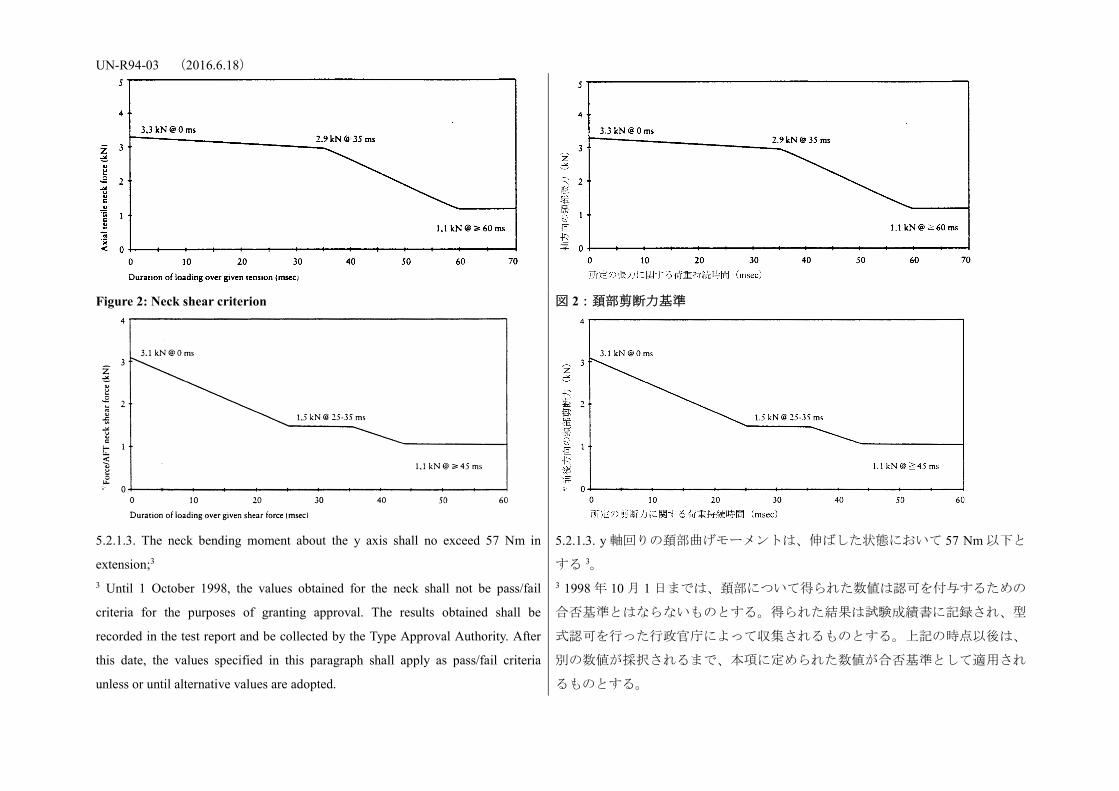
5.2.1.2. The Injury Criteria for the neck (NIC) shall not exceed the values
shown in Figures 1 and 2;3 3 Until 1 October 1998, the values obtained for the neck shall not be pass/fail
criteria for the purposes of granting approval. The results obtained shall be
recorded in the test report and be collected by the Type Approval Authority. After
this date, the values specified in this paragraph shall apply as pass/fail criteria
unless or until alternative values are adopted.
5.2.1.2. 頚部負傷基準(NIC)は図 1 及び 23 に示された数値以下とする。 3 1998 年 10 月 1 日までは、頚部について得られた数値は認可を付与するための
合否基準とはならないものとする。得られた結果は試験成績書に記録され、型
式認可を行った行政官庁によって収集されるものとする。上記の時点以後は、
別の数値が採択されるまで、本項に定められた数値が合否基準として適用され
るものとする。
Figure 1: Neck tension criterion 図 1:頚部張力基準
UN-R94-03 (2016.6.18)
Figure 2: Neck shear criterion
図 2:頚部剪断力基準
5.2.1.3. The neck bending moment about the y axis shall no exceed 57 Nm in
extension;3 3 Until 1 October 1998, the values obtained for the neck shall not be pass/fail
criteria for the purposes of granting approval. The results obtained shall be
recorded in the test report and be collected by the Type Approval Authority. After
this date, the values specified in this paragraph shall apply as pass/fail criteria
unless or until alternative values are adopted.
5.2.1.3. y 軸回りの頚部曲げモーメントは、伸ばした状態において 57 Nm 以下と
する 3。 3 1998 年 10 月 1 日までは、頚部について得られた数値は認可を付与するための
合否基準とはならないものとする。得られた結果は試験成績書に記録され、型
式認可を行った行政官庁によって収集されるものとする。上記の時点以後は、
別の数値が採択されるまで、本項に定められた数値が合否基準として適用され
るものとする。
UN-R94-03 (2016.6.18) 5.2.1.4. The thorax compression criterion (ThCC) shall not exceed 42 mm; 5.2.1.4. 胸部圧縮基準(ThCC)は 42 mm 以下とする。
5.2.1.5. The viscous criterion (V * C) for the thorax shall not exceed 1,0 m/s; 5.2.1.5. 胸部粘性基準(V*C)は 1.0 m/s 以下とする。
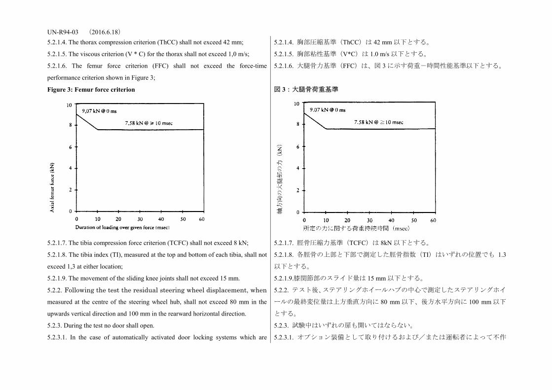
5.2.1.6. The femur force criterion (FFC) shall not exceed the force-time
performance criterion shown in Figure 3;
5.2.1.6. 大腿骨力基準(FFC)は、図 3 に示す荷重-時間性能基準以下とする。
Figure 3: Femur force criterion
図 3:大腿骨荷重基準
5.2.1.7. The tibia compression force criterion (TCFC) shall not exceed 8 kN; 5.2.1.7. 脛骨圧縮力基準(TCFC)は 8kN 以下とする。
5.2.1.8. The tibia index (TI), measured at the top and bottom of each tibia, shall not
exceed 1,3 at either location;
5.2.1.8. 各脛骨の上部と下部で測定した脛骨指数(TI)はいずれの位置でも 1.3
以下とする。
5.2.1.9. The movement of the sliding knee joints shall not exceed 15 mm. 5.2.1.9.膝関節部のスライド量は 15 mm 以下とする。
5.2.2. Following the test the residual steering wheel displacement, when measured at the centre of the steering wheel hub, shall not exceed 80 mm in the
upwards vertical direction and 100 mm in the rearward horizontal direction.
5.2.2. テスト後、ステアリングホイールハブの中心で測定したステアリングホイ
ールの最終変位量は上方垂直方向に 80 mm 以下、後方水平方向に 100 mm 以下
とする。
5.2.3. During the test no door shall open. 5.2.3. 試験中はいずれの扉も開いてはならない。
5.2.3.1. In the case of automatically activated door locking systems which are 5.2.3.1. オプション装備として取り付けるおよび/または運転者によって不作
UN-R94-03 (2016.6.18) installed optionally and/or which can be de-activated by the driver, this
requirement shall be verified by using one of the following 2 test procedures, at the
choice of the manufacturer:
動にすることができる自動ドアロックシステムの場合、メーカーの選択により、
以下の 2 つのテスト手順のいずれかを用いて本要件を確認するものとする;
5.2.3.1.1. If testing in accordance with Annex 3, paragraph 1.4.3.5.2.1., the
manufacturer shall in addition demonstrate to the satisfaction of the Technical
Service (e.g. manufacturer’s in-house data) that, in the absence of the system or
when the system is de-activated, no door will open in case of the impact.
5.2.3.1.1. 附則 3、1.4.3.5.2.1 項に従ってテストする場合は、メーカーは、さらに、
当該システムが存在しない時または不作動状態である時に衝突の際にドアが開
かないことを、技術機関が納得するように(例:メーカーの社内データ)証明
するものとする。
5.2.3.1.2. The test is conducted in accordance with Annex 3, paragraph 1.4.3.5.2.2. 5.2.3.1.2. テストを附則 3、1.4.3.5.2.2 項に従って実施する。
5.2.4. After the impact, the side doors shall be unlocked. 5.2.4. 衝突後、サイドドアのロックは解除されるものとする。
5.2.4.1. In the case of vehicles equipped with an automatically activated door
locking system, the doors shall be locked before the moment of impact and be
unlocked after the impact.
5.2.4.1. 自動ドアロックシステムが装備された車両の場合、ドアは衝突の瞬間
の前にロックされ、衝突後にロックが解除されるものとする。
5.2.4.2. In the case of vehicles equipped with automatically activated door locking
systems which are installed optionally and/or which can be de-activated by the
driver, this requirement shall be verified by using one of the following 2 test
procedures, at the choice of the manufacturer:
5.2.4.2. オプション装備として取り付けるおよび/または運転者によって不作
動にすることができる自動ドアロックシステムが装備された車両の場合、メー
カーの選択により、以下の 2 つのテスト手順のいずれかを用いて本要件を確認
するものとする:
5.2.4.2.1. If testing in accordance with Annex 3, paragraph 1.4.3.5.2.1, the
manufacturer shall in addition demonstrate to the satisfaction of the Technical
Service (e.g. manufacturer’s in-house data) that, in the absence of the system or
when the system is de-activated, no locking of the side doors shall occur during the
impact.
5.2.4.2.1. 附則 3、1.4.3.5.2.1 項に従ってテストする場合は、メーカーは、さらに、
当該システムが存在しない時または不作動状態である時に衝突中にサイドドア
のロックがかからないことを、技術機関が納得するように(例:メーカーの社
内データ)証明するものとする。
5.2.4.2.2. The test is conducted in accordance with Annex 3, paragraph 1.4.3.5.2.2. 5.2.4.2.2. テストを附則 3、1.4.3.5.2.2 項に従って実施する。
5.2.5. After the impact, it shall be possible, without the use of tools, except for
those necessary to support the weight of the dummy:
5.2.5. 衝突後、ダミーの重量を支持するために必要なものを除き、工具を使わず
に次の 5.2.5.1 項から 5.2.5.3 項までに掲げることが可能であるものとする。
5.2.5.1. To open at least one door, if there is one, per row of seats and, where there
is no such door, to move the seats or tilt their backrests as necessary to allow the
5.2.5.1. 扉がある場合には、座席列ごとに最低1箇所の扉が開けられること。扉
がない場合には、全乗員が避難するために必要なだけ座席又は座席背面を動か
UN-R94-03 (2016.6.18) evacuation of all the occupants; this is, however, only applicable to vehicles having
a roof of rigid construction;
すことができること。ただし、この規定は剛性構造のルーフを有する車両にの
み適用される。
5.2.5.2. To release the dummies from their restraint system which, if locked, shall
be capable of being released by a maximum force of 60 N on the centre of the
release control;
5.2.5.2. ダミーを拘束装置から外す場合には、解除装置の中心に最大 60N の荷
重をかけることにより解除できること。
5.2.5.3. To remove the dummies from the vehicle without adjustment of the seats. 5.2.5.3. 座席を調整せずにダミーを車両から取り出せること。
5.2.6. In the case of a vehicle propelled by liquid fuel, no more than slight leakage
of liquid from the fuel feed installation shall occur on collision.
5.2.6. 液体燃料を使用する車両の場合、衝突時に燃料供給装置から液体がわずか
しか漏れないものとする。
5.2.7. If there is continuous leakage of liquid from the fuel-feed installation after
the collision, the rate of leakage shall not exceed 30 g/min; if the liquid from the
fuel-feed system mixes with liquids from the other systems and the various liquids
cannot easily be separated and identified, all the liquids collected shall be taken
into account in evaluating the continuous leakage.
5.2.7. 衝突後、燃料供給装置から液体が継続的に漏れた場合、その漏出率は 1 分
当たり 30 g を超えてはならない。ただし、燃料供給装置から漏れた液体が他の
装置から漏れた液体と混ざり、これら複数の液体が容易に選別及び断定ができ
ないときは、回収された全ての液体を継続的漏出の評価計算に入れるものとす
る。
5.2.8. Following the test conducted in accordance with the procedure defined in
Annex 3 to this Regulation, the electrical power train operating on high voltage,
and the high voltage components and systems, which are galvanically connected to
the high voltage bus of the electric power train, shall meet the following
requirements:
5.2.8. 本規則の附則 3 に定められた手順に従って試験を実施した後、高電圧で作
動する電動パワートレーン並びに電動パワートレーンの高電圧回路に直流電気
的に接続された高電圧構成部品及びシステムは、以下の要件を満たすものとす
る。
5.2.8.1. Protection against electrical shock
After the impact at least one of the four criteria specified in paragraph 5.2.8.1.1.
through paragraph 5.2.8.1.4.2. below shall be met.
If the vehicle has an automatic disconnect function, or device(s) that galvanically
divide the electric power train circuit during driving condition, at least one of the
following criteria shall apply to the disconnected circuit or to each divided circuit
individually after the disconnect function is activated.
However criteria defined in 5.2.8.1.4. below shall not apply if more than a single
5.2.8.1. 感電に対する保護
衝突試験後、下記の 5.2.8.1.1 項から 5.2.8.1.4.2 項までに規定された 4 つの基準の
うち少なくとも 1 つを満たすものとする。
試験車両が、運転状態において電動パワートレーンを直流電気的に分割する自
動遮断機能又は装置を有している場合には、遮断機能の作動後において、遮断
された回路又は互いに分割された回路ごとに次の要件のいずれかを適用するも
のとする。
ただし、保護等級 IPXXB で保護されていない異なる電位を有する高電圧回路
UN-R94-03 (2016.6.18) potential of a part of the high voltage bus is not protected under the conditions of
protection degree IPXXB.
If the test is performed under the condition that part(s) of the high voltage system
are not energized, the protection against electrical shock shall be proved by either
paragraph 5.2.8.1.3. or paragraph 5.2.8.1.4. for the relevant part(s).
For the coupling system for charging the REESS, which is not energized during
driving conditions, at least one of the four criteria specified in paragraphs 5.2.8.1.1.
to 5.2.8.1.4. shall be met.
の部位が 2 か所以上存在する場合においては、下記の 5.2.8.1.4 項に規定する要
件は適用しない。
高電圧回路に通電しない状態で衝突試験を実施する場合には、感電に対する保
護は、関連する部位に対して 5.2.8.1.3 項又は 5.2.8.1.4 項のいずれかの要件を満
たすものでなければならない。
走行状態では通電しない REESS 充電系連結システムについては、5.2.8.1.1 項か
ら 5.2.8.1.4 項までに規定された 4 つの基準のうちの少なくとも 1 つを満たすも
のとする。
5.2.8.1.1. Absence of high voltage
The voltages Vb, V1 and V2 of the high voltage buses shall be equal or less than 30
VAC or 60 VDC as specified in paragraph 2. of Annex 11.
5.2.8.1.1. 高電圧の消失
高電圧回路の電圧 Vb、V1及び V2 は、附則 11 の 2 項に規定された通り、交流 30
V又は直流 60V以下とする。
5.2.8.1.2. Low electrical energy
The total energy (TE) on the high voltage buses shall be less than 2.0 joules when
measured according to the test procedure as specified in paragraph 3. of Annex 11
with the formula (a).
Alternatively the total energy (TE) may be calculated by the measured voltage Vb
of the high voltage bus and the capacitance of the X-capacitors (Cx) specified by
the manufacturer according to formula (b) of paragraph 3. of Annex 11.
The energy stored in the Y-capacitors (TEy1, TEy2) shall also be less than 2.0 joules.
This shall be calculated by measuring the voltages V1 and V2 of the high voltage
buses and the electrical chassis, and the capacitance of the Y-capacitors specified
by the manufacturer according to formula (c) of paragraph 3. of Annex 11.
5.2.8.1.2. 低電気エネルギー
高電圧回路の総エネルギー(TE)は、附則 11 の 3 項に規定する試験手順に従っ
て式(a)を用いて測定した場合、2.0 ジュール未満とする。
これに代えて、総エネルギー(TE)は、高電圧回路の電圧測定値 Vb 及び附則
11 の 3 項の式(b)に従ってメーカーが指定する X-キャパシタの静電容量(Cx)
を用いて計算してもよい。
Y-キャパシタに貯蔵されるエネルギー(TEy1、TEy2)もまた、2.0 ジュール未
満とする。Y-キャパシタに貯蔵されるエネルギーは、高電圧回路及び電気的シ
ャシの間の電圧測定値V1 及びV2 並びにメーカーが指定する Y-キャパシタの
静電容量(Cy1、Cy2)を用いて、附則 11 の 3 項の式(c)に従って計算により求め
るものとする。
5.2.8.1.3. Physical protection
For protection against direct contact with high voltage live parts, the protection
degree IPXXB shall be provided.
5.2.8.1.3. 接触保護
高電圧活電部への直接接触に対する保護は、保護等級 IPXXB を満たすものでな
ければならない。
UN-R94-03 (2016.6.18)
In addition, for protection against electrical shock which could arise from indirect
contact, the resistance between all exposed conductive parts and the electrical
chassis shall be lower than 0.1 ohm when there is current flow of at least 0.2
ampere.
This requirement is satisfied if the galvanic connection has been made by welding.
さらに、間接接触から生じる可能性がある感電に対する保護については、全て
の露出導電部と電気的シャシとの間の抵抗値は、0.2 A 以上の電流を流した状態
で 0.1 Ω未満とする。
ただし、直流電気的接続が溶接により行われている場合は、当該抵抗値は 0.1
Ω未満とみなす。
5.2.8.1.4. Isolation resistance
The criteria specified in the paragraphs 5.2.8.1.4.1. and 5.2.8.1.4.2. below shall be
met.
The measurement shall be conducted in accordance with paragraph 5. of Annex 11.
5.2.8.1.4. 絶縁抵抗
絶縁抵抗は、下記 5.2.8.1.4.1 項及び 5.2.8.1.4.2 項に規定された要件を満たすもの
とする。
測定は、附則 11 の 5 項に従って実施されるものとする。
5.2.8.1.4.1. Electrical power train consisting of separate DC- or AC-buses
If the AC high voltage buses and the DC high voltage buses are galvanically
isolated from each other, isolation resistance between the high voltage bus and the
electrical chassis (Ri, as defined in paragraph 5. of Annex 11) shall have a
minimum value of 100 omega/V of the working voltage for DC buses, and a
minimum value of 500 omega/V of the working voltage for AC buses.
5.2.8.1.4.1. 直流回路及び交流回路が分割された電動パワートレーンの場合
直流の高電圧回路及び交流の高電圧回路が互いに直流電気的に絶縁されている
場合には、高電圧回路及び電気的シャシの間の絶縁抵抗(附則 11 の 5 項の定義
による Ri)は、直流回路用の作動電圧 1V 当たり 100Ω以上であり、かつ、交流
回路用の作動電圧 1V 当たり 500Ω以上であるものとする。
5.2.8.1.4.2. Electrical power train consisting of combined DC- and AC-buses
If the AC high voltage buses and the DC high voltage buses are galvanically
connected isolation resistance between the high voltage bus and the electrical
chassis (Ri, as defined in paragraph 5. of Annex 11) shall have a minimum value of
500 omega/V of the working voltage.
However, if the protection degree IPXXB is satisfied for all AC high voltage buses
or the AC voltage is equal or less than 30 V after the vehicle impact, the isolation
resistance between the high voltage bus and the electrical chassis (Ri, as defined in
5.2.8.1.4.2. 直流回路及び交流回路が接続された電動パワートレーンの場合
直流の高電圧回路及び交流の高電圧回路が互いに直流電気的に接続されている
場合には、高電圧回路と電気的シャシとの間の絶縁抵抗(附則 11 の 5 項の定義
による Ri)は、作動電圧 1V 当たり 500Ω以上であるものとする。
ただし、全ての交流の高電圧回路が保護等級 IPXXB を満たし、又は交流電圧が
車両の衝突後 30V 以下である場合には、高電圧回路と電気的シャシとの間の絶
縁抵抗(附則 11 の 5 項の定義による Ri)は、作動電圧 1V 当たり 100Ω以上で
あるものとする。
UN-R94-03 (2016.6.18) paragraph 5. of Annex 11) shall have a minimum value of 100 omega/V of the
working voltage.
5.2.8.2. Electrolyte spillage
In the period from the impact until 30 minutes after no electrolyte from the REESS
shall spill into the passenger compartment and no more than 7 per cent of
electrolyte shall spill from the REESS except open type traction batteries outside
the passenger compartment. For open type traction batteries no more than 7 per
cent with a maximum of 5.0 liters shall spill outside the passenger compartment.
The manufacturer shall demonstrate compliance in accordance with paragraph 6. of
Annex 11.
5.2.8.2. 電解液の漏出
衝突試験後 30 分間は、REESS の電解液が車室内に漏出してはならない。
また、車室外に設置された開放式駆動用蓄電池を除き、駆動用蓄電池モジュー
ルの電解液の車両外部への漏出が、電解液総量の 7%を超えてはならない。開放
式駆動用蓄電池の場合には、電解液の車両外部への漏出は、電解液総量の 7%を
超えず、かつ、5ℓ 以下であるものとする。
メーカーは、附則 11 の 6 項に基づき、上記への適合を証明するものとする。
5.2.8.3. REESS retention
REESS located inside the passenger compartment shall remain in the location in
which they are installed and REESS components shall remain inside REESS
boundaries.
No part of any REESS that is located outside the passenger compartment for
electric safety assessment shall enter the passenger compartment during or after the
impact test.
The manufacturer shall demonstrate compliance in accordance with paragraph 7. of
Annex 11.
5.2.8.3. REESS の位置保持
車室内に設置される REESS は、所定の位置に固定されたままでなければならず、
また、REESS 構成部品は REESS の境界内に配置されるものとする。
電気安全性試験のために車室外に設置された REESS は、そのいずれの部分も衝
突試験中又は衝突試験後に車室に侵入しないものとする。
メーカーは、附則 11 の 7 項に基づき、上記への適合を証明するものとする。
6. Instructions for users of vehicles equipped with airbags 6. エアバッグを装備した場合の使用者への周知方法
6.1. The vehicle shall carry information to the effect that it is equipped with airbags
for seats.
6.1. 車両には、座席にエアバッグが装備されている旨の情報を表示するものと
する。
6.1.1. For a vehicle fitted with an airbag assembly intended to protect the driver,
this information shall consist of the inscription "AIRBAG" located in the interior of
6.1.1. 運転者の保護を目的としてエアバッグを取り付けた場合には、ステアリン
グホイールの周囲に「AIRBAG」と表示するものとする。この表示は耐久性のあ
UN-R94-03 (2016.6.18) the circumference of the steering wheel; this inscription shall be durably affixed
and easily visible.
るものであり、かつ容易に視認できるものでなければならない。
6.1.2. For a vehicle fitted with a passenger airbag intended to protect occupants
other than the driver, this information shall consist of the warning label described
in paragraph 6.2. below
6.1.2. 運転者以外の乗員を保護することを目的としてパッセンジャー・エアバッ
グを取り付けた場合には、下記 6.2 項に記載する内容をコーションラベルに記載
するものとする。
6.2. A vehicle fitted with one or more passenger frontal protection airbags shall
carry information about the extreme hazard associated with the use of
rearward-facing child restraints on seats equipped with airbag assemblies.
6.2. 1 つ又は複数の前部保護用パッセンジャー・エアバッグを取り付けた場合に
は、幼児拘束装置をエアバッグが作動する座席に後向きに取り付けて使用した
場合における危険性に関する情報を記載するものとする。
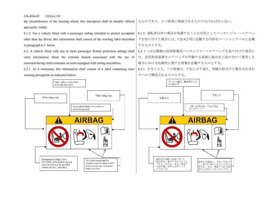
6.2.1. As a minimum, this information shall consist of a label containing clear
warning pictograms as indicated below:
6.2.1. 少なくとも、この情報は、下記に示す通り、明確な絵文字と警告文を含む
ラベルで構成されるものとする。

UN-R94-03 (2016.6.18)
The overall dimensions shall be at least 120 x 60 mm or the equivalent area.
The label shown above may be adapted in such a way that the layout differs from
the example above; however, the content shall meet the above prescriptions.
全体の寸法は、少なくとも 120 x 60 mm 又は同等の面積とする。
上記の警告の絵文字と警告文の内容は、上に示すものに従わなければならない。
ただし、配置の変更は可能とする。
6.2.2. In the case of a frontal protection airbag on the front passenger seat, the
warning shall be durably affixed to each face of the passenger front sun visor in
such a position that at least one warning on the sun visor is visible at all times,
irrespective of the position of the sun visor. Alternatively, one warning shall be
located on the visible face of the stowed sun visor and a second warning shall be
located on the roof behind the visor, so, at least one warning is visible all times. It
shall not be possible to easily remove the warning label from the visor and the roof
without any obvious and clearly visible damage remaining to the visor or the roof
in the interior of the vehicle.
If the vehicle does not have a sun visor or roof, the warning label shall be
positioned in a location where it is clearly visible at all times.
In the case of a frontal protection airbag for other seats in the vehicle, the warning
must be directly ahead of the relevant seat, and clearly visible at all times to
someone installing a rear-facing child restraint on that seat. The requirements of
this paragraph and paragraph 6.2.1. do not apply to those seating positions
equipped with a device which automatically deactivates the frontal protection
airbag assembly when any rearward facing child restraint is installed.
6.2.2. 助手席の前部保護用エアバッグの場合、コーションラベルは助手席用サン
バイザの両面に貼付することにより、サンバイザの位置にかかわらず、いずれ
かのコーションラベルが常時視認できるものとする。これに代えて、サンバイ
ザの収納時に視認できる面と収納部の車室面にコーションラベルを貼付するこ
とによって、いずれかのコーションラベルが常時視認できるようにしてもよい。
コーションラベルは、バイザー及びルーフから剥がす場合には、必ず明確でか
つはっきりと見えるダメージがバイザー又は車内のルーフに残るよう貼付され
るものとする。
車両にサンバイザ又はルーフがない場合は、常に明確に視認できる位置にコー
ションラベルを貼付するものとする。
車両の助手席以外の前部保護用エアバッグの場合、幼児拘束装置を後向きに当
該座席に取り付けようとする人が常に容易に視認できるように、コーションラ
ベルは当該座席のすぐ前に貼付しなければならない。6.2.1 項及び 6.2.2 項の要件
は、後向き幼児拘束装置が取り付けられると前部保護用エアバッグを自動的に
作動しないようにする装置を備えた座席には適用しない。
6.2.3. Detailed information, making reference to the warning, shall be contained in
the owner's manual of the vehicle; as a minimum, the following text in all official
languages of the country or countries where the vehicle could reasonably be
expected to be registered (e.g. within the territory of the European Union, in Japan,
in Russian Federation or in New Zealand, etc.), shall at least include:
6.2.3. 少なくとも以下の内容を含むコーションラベルの詳細情報を、当該自動車
のオーナーズマニュアルに、車両の登録が合理的に予定される全ての国(例:
欧州連合の域内、日本、ロシア連邦又はニュージーランド等)の公用語で記載
するものとする。

UN-R94-03 (2016.6.18)
"NEVER use a rearward facing child restraint on a seat protected by an ACTIVE
AIRBAG in front of it, DEATH or SERIOUS INJURY to the CHILD can occur"
The text shall be accompanied by an illustration of the warning label as found in
the vehicle. The information shall be easily found in the owner's manual (e.g.
specific reference to the information printed on the first page, identifying page tab
or separate booklet, etc.)
The requirements of this paragraph do not apply to vehicles of which all passenger
seating positions are equipped with a device which automatically deactivates the
frontal protection airbag assembly when any rearward facing child restraint is
installed.
「エアバックが作動して保護される座席には、後向き幼児拘束装置を装着しな
いで下さい。幼児が死亡したり、重傷を負う可能性があります。」
この内容と共に、当該車両に貼付されるコーションラベルの図解を収録するも
のとする。当該情報は、オーナーズマニュアルの中で容易に見つけることがで
きるよう収録するものとする(例:当該情報への特別な言及が最初のページ、
確認用のページタブ又は別途の小冊子に記載される等)。
本 6.2.3 項の要件は、後向き幼児拘束装置が取り付けられると前部保護用エアバ
ッグを自動的に作動しないようにする装置が全ての座席に装備された車両には
適用しない。
7. Modification and extension of approval of the vehicle type 7. 車両型式認可の変更及び拡大
7.1. Any modification affecting the structure, the number of seats, the interior trim
or fittings, or the position of the vehicle controls or of mechanical parts which
might affect the energy-absorption capability of the front of the vehicle shall be
brought to the notice of the Type Approval Authority granting approval. The Type
Approval Authority may then either:
7.1. 車両前部のエネルギー吸収性能に影響を及ぼす、構造、席数、内装トリム
若しくは部品、又は操縦装置若しくは機械部品の位置に影響がある全ての変更
は、型式認可を行なった行政官庁にその旨を届出しなければならない。当該行
政官庁は、以下に規定するいずれかの処置を行うことができる。
7.1.1. Any modification affecting the structure, the number of front seats, the interior trim or fittings, or the position of the vehicle controls or of mechanical parts which might affect the energy-absorption capability of the front of the vehicle shall be brought to the notice of the Type Approval Authority granting approval. The Type Approval Authority may then either:
7.1.1. 実施された変更が安全上著しい悪影響を与えるおそれがない場合には、車
両が引き続き要件に適合すると判断を下すこと。
7.1.2. Require the Technical Service responsible for conducting the tests to carry 7.1.2. 試験を実施した技術機関に、変更の内容に基づき、7.1.2.1 項から 7.1.2.2
UN-R94-03 (2016.6.18) out a further test, among those described below, according to the nature of the
modifications;
項までに掲げる試験の実施を要求すること。
7.1.2.1. Any modification of the vehicle affecting the general form of the structure
of the vehicle and/or any increase in mass greater than 8 per cent which in the
judgement of the authority would have a marked influence on the results of the
tests shall require a repetition of the test as described in Annex 3;
7.1.2.1. 試験結果に顕著な影響をもたらすであろうと当該行政官庁が判断する、
車両構造の全般的形態に影響する車両の改良及び/又は 8%を超える質量増加が
生じた場合には、附則 3 に記載する試験の再実施が義務付けられるものとする。
7.1.2.2. If the modifications concern only the interior fittings, if the mass does not increase by more than 8 per cent and if the number of front seats initially provided in the vehicle remains the same, the following shall be carried out:
7.1.2.2. 変更が内装部品のみに関わり、質量の変更が 8%を超えず、かつ、当初
の車両に備えられた前部座席数に変更がない場合には、7.1.2.2.1 項から 7.1.2.2.2
項までに掲げる試験を実施するものとする。
7.1.2.2.1. A simplified test as provided for in Annex 7 and/or, 7.1.2.2.1. 附則 7 に定める簡略試験、及び/又は、
7.1.2.2.2. A partial test as defined by the Technical Service in relation to the
modifications made.
7.1.2.2.2. 実施された変更に関連して技術機関が指定する部分試験。
7.2. Confirmation or refusal of approval, specifying the alterations, shall be
communicated by the procedure specified in paragraph 4.3. above to the Parties to
the Agreement which apply this Regulation.
7.2. 行政官庁は、認可の承認又は拒否を行った場合には、変更点を明記の上、
上記 4.3 項に規定した手続きにより、本規則を採用する協定締約国に通知するも
のとする。
7.3. The Type Approval Authority issuing the extension of approval shall assign a
series number for such an extension and inform thereof the other Parties to the
1958 Agreement applying this Regulation by means of a communication form
conforming to the model in Annex 1 to this Regulation.
7.3. 型式認可の拡大を行う行政官庁は、当該拡大に対して通し番号を割り当て、
本規則を採用する他の 1958 年協定締約国に、本規則附則 1 のひな形に準拠する
通知書により、その旨を通知するものとする。
8. Conformity of production
The conformity of production procedures shall comply with those set out in the
Agreement, Appendix 2 (E/ECE/324-E/ECE/TRANS/505/Rev.2) with the
following requirements:
8. 生産の適合性
生 産 の 適 合 性 に 係 る 手 続 き は 、 協 定 規 則 の 付 録 2
(E/ECE/324-E/ECE/TRANS/505/Rev.2)に規定された手順及び 8.1 項から 8.3 項
までに規定する要件に適合しなければならない。
8.1. Every vehicle approved under this Regulation shall conform to the vehicle 8.1. 本規則に基づいて認可された各車両は、前面衝突時の車両の乗員保護に影
UN-R94-03 (2016.6.18) type approved, as regards features contributing to the protection of the occupants of
the vehicle in the event of a frontal collision.
響する特性に関して、認可を受けた車両型式に適合させなければならない。
8.2. The holder of the approval shall ensure that for each type of vehicle at least the
tests concerning the taking of measurements are carried out.
8.2. 認可を受けた者は各型式の車両について、少なくとも測定の実施に関する
試験を確実に行うものとする。
8.3. The Type Approval Authority which has granted type approval may at any time
verify the conformity control methods applied in each production facility. The
normal frequency of these verifications shall be once every two years.
8.3. 型式認可を行った行政官庁は、各生産施設で採用した適合性管理方法をい
つでも確認することができる。当該確認は、通常 2 年に 1 度の頻度で実施され
るものとする。
9. Penalties for non-conformity of production 9. 生産の不適合に対する罰則
9.1. The approval granted in respect of a vehicle type pursuant to this Regulation
may be withdrawn if the requirement laid down in paragraph 7.1. above is not
complied with or if the vehicle or vehicles selected have failed to pass the checks
prescribed in paragraph 7.2. above.
9.1. 本規則に基づく車両型式に関する認可は、上記 7.1 項の要件に適合しない場
合又はサンプル車両が上記 7.2 項に定める検査に合格しなかった場合には、取り
消されることがある。
9.2. If a Contracting Party to the Agreement applying this Regulation withdraws an
approval it has previously granted, it shall forthwith so notify the other Contracting
Parties applying this Regulation, by means of a communication form conforming
to the model in Annex 1 to this Regulation.
9.2. 本規則を採用する協定締約国は、既に行われた認可を取り消す場合には、
本規則附則 1 のひな形に準拠する通知書により、ただちに本規則を採用してい
る他の協定締約国に通知するものとする。
10. Production definitively discontinued
If the holder of the approval completely ceases to manufacture the type of vehicle
approved in accordance with the Regulation, he shall so inform the Type Approval
Authority which granted the approval. Upon receiving the relevant communication
that Authority shall inform thereof the other Parties to the 1958 Agreement
applying this Regulation by means of a communication form conforming to the
model in Annex 1 to this Regulation.
10. 生産中止
認可を受けた者は、本規則に基づく車両型式の生産を中止する場合には、型式
認可を付与した行政官庁に対して、その旨を届出しなければならない。届出を
受けた行政官庁は、本規則を採用する他の 1958 年協定締約国に対して、本規則
附則 1 のひな形に準拠する通知書により、その旨を通知するものとする。
UN-R94-03 (2016.6.18) 11. Transitional provisions 11. 過渡規定
11.1. As from the official date of entry into force of Supplement 4 to the 01 series
of amendments, no Contracting Party applying this Regulation shall refuse to grant
type approval under this Regulation as amended by Supplement 4 to the 01 series
of amendments.
11.1. 第 1 改訂版補足第 4 号の正式な発効日より、協定締約国は、第 1 改訂版補
足 4 により改訂された本規則に準拠した型式認可の付与を拒否しないものとす
る。
11.2. As from 23 June 2013, Contracting Parties applying this Regulation shall
grant type approvals only to those types of vehicles which comply with the
requirements of this Regulation as amended by Supplement 4 to the 01 series of
amendments.
11.2. 2013 年 6 月 23 日より、協定締約国は、車両型式が第 1 改訂版補足第 4 号
により改訂された本規則の要件を満たす場合にのみ型式認可を付与するものと
する。
11.3. As long as there are no requirements in this Regulation with regard to the
protection of the occupants by means of a full frontal impact test, Contracting
Parties may continue to apply the requirements already in force for that purpose at
the time of acceding to this Regulation.
11.3. 本規則に前面衝突試験による乗員の保護に関する完全な要件がない間は、
締約国は、本規則への加盟時に既に発効していた本目的に関する要件を適用し
続けることができる。
11.4. As from the official date of entry into force of the 02 series of amendments,
no Contracting Party applying this Regulation shall refuse to grant type approval
under this Regulation as amended by the 02 series of amendments.
11.4. 第 2 改訂版の正式な発効日より、本規則を採用する締約国は、第 2 改訂版
により改訂された本規則に基づく型式認可の付与を拒否しないものとする。
11.5. As from 24 months after the official date of entry into force of the 02 series of
amendments, Contracting Parties applying this Regulation shall grant type
approvals only to those types of vehicle which comply with the requirements of
this Regulation as amended by the 02 series of amendments.
However, in the case of vehicles having an electrical power train operating on high
voltage, an additional period of 12 months is granted provided that the
manufacturer demonstrates, to the satisfaction of the Technical Service, that the
vehicle provides equivalent levels of safety to those required by this Regulation as
amended by the 02 series of amendments.
11.5. 第 2 改訂版の正式な発効日から 24 箇月後より、協定締約国は、第 2 改訂
版により改訂された本規則の要件に適合する車両型式に限り、認可を付与する
ものとする。
ただし、高電圧で作動する電動パワートレーンを有する車両の場合、当該車両
が第 2 改訂版により改訂された本規則で要求されている安全性と同等レベルの
安全を提供することをメーカーが証明し、これに技術機関が納得することを条
件に、更に 12 箇月の期間が与えられる。
UN-R94-03 (2016.6.18) 11.6. Contracting Parties applying this Regulation shall not refuse to grant
extensions of approvals issued to the preceding series of amendments to this
Regulation, when this extension does not entail any change to the propulsion
system of the vehicle.
However, as from 48 months after the official date of entry into force of the 02
series of amendments, extensions to approvals issued to the previous series of
amendments shall not be granted in respect of vehicles having an electrical power
train operating on high voltage.
11.6.協定締約国は、本規則の旧改訂版に従って行われた認可の拡大が車両の駆
動システムの変更を伴わない場合には、この拡大を拒否してはならない。
ただし、第 2 改訂版の正式な発効日から 48 カ月後より、旧改訂版に従って行わ
れた認可の拡大は、高電圧で作動する電動パワートレーンを備えた車両に対し
ては認めてはならない。
11.7. Where at the time of entry into force of the 02 series of amendments to this
Regulation, national requirements exist to address the safety provisions of vehicles
having an electrical power train operating on high voltage, those Contracting
Parties applying this Regulation may refuse national approval of such vehicles not
meeting the national requirements, unless these vehicles are approved to the 02
series of amendments to this Regulation.
11.7. 本規則の第 2 改訂版の発効時に、高電圧で作動する電動パワートレーンを
備えた車両の安全規定に対応するための国内要件が存在する場合には、協定締
約国は、当該国内要件を満たさない車両の国内認可を拒否することができる。
ただし、当該車両が本規則の第 2 改訂版に従って認可されている場合はこの限
りではない。
11.8. As from 48 months after the entry into force of the 02 series of amendments
to this Regulation, Contracting Parties applying this Regulation may refuse
national or regional type approval and may refuse first national or regional
registration (first entry into service) of a vehicle having an electrical power train
operating on high voltage which does not meet the requirements of the 02 series of
amendments to this Regulation.
11.8. 本規則の第 2 改訂版が発効されてから 48 カ月後より、本規則を採用する
締約国は、本規則の第 2 改訂版の要件を満たさない高電圧で作動する電動パワ
ートレーンを備えた車両について、その国内又は地域内における型式認可を拒
否することができ、また、その国内又は地域内の初回登録(最初の提供開始)
を拒否することができる。
11.9. Contracting Parties applying the Regulation shall continue to accept approvals to the 01 series of amendments to this Regulation, for the vehicles which are not affected by the 02 series of amendments.
11.9. 本規則の第 2 改訂版の影響を受けない車両については、本規則を適用する
締約国は引き続き本規則の 01 改訂シリーズに基づく認可を受け入れるものとす
る。
11.10. Until 18 months after the date of entry into force of the Supplement 4 to the
02 series of amendments to this Regulation, Contracting Parties applying this
11.10. 本規則を適用する締約国は、本規則の 02 改訂シリーズ補足 4 の発効日の
18 ヶ月後までは、補足 4 の規定を考慮せずに引き続き本規則の 02 改訂シリーズ
UN-R94-03 (2016.6.18) Regulation can continue to grant type approvals to the 02 series of amendments to
this Regulation without taking into account the provisions of Supplement 4.
に従って型式認可を付与することができる。
11.11. As from the official date of entry into force of the 03 series of amendments,
no Contracting Party applying this Regulation shall refuse to grant approval under
this Regulation as amended by the 03 series of amendments.
11.11. 03 改訂シリーズの正式発効日以降、本規則を適用する締約国は、03 改
訂シリーズにより改訂された本規則に基づく認可の付与を拒否しないものとす
る。
11.12. As from 1 September 2018, Contracting Parties applying this Regulation
shall grant approvals only to those types of vehicle which comply with the
requirements of this Regulation as amended by the 03 series of amendments.
11.12. 2018 年 9 月 1 日以降、本規則を適用する締約国は、03 改訂シリーズに
より改訂された本規則の要件に適合している車両型式に限り認可を付与するも
のとする。
11.13. Contracting Parties applying this Regulation shall not refuse to grant
extensions of approvals for existing types which have been granted according to
the preceding series of amendments to this Regulation.
11.13. 本規則を適用する締約国は、本規則の先行改訂シリーズに従って付与さ
れた既存型式に関する認可の拡大の付与を拒否しないものとする。
11.14. Contracting Parties applying the Regulation shall continue to accept
approvals to the 01 series of amendments to the Regulation, granted before 23 June
2013 or 2014, as foreseen in paragraph 11.5. above.
11.14. 本規則を適用する締約国は、上記 11.5 項で予測したとおり、2013 年ま
たは 2014 年の 6 月 23 日より前に付与された、本規則の 01 改訂シリーズに基づ
く認可を引き続き受け入れるものとする。
11.15. Contracting Parties applying the Regulation shall continue to accept
approvals to the 02 series of amendments to the Regulation, granted before 1
September 2018.
11.15. 本規則を適用する締約国は、2018 年 9 月 1 日より前に付与された、本規
則の 02 改訂シリーズに基づく認可を引き続き受け入れるものとする。
12. Names and addresses of Technical Services responsible for conducting
approval tests, and of Type Approval Authorities
The Contracting Parties to the Agreement applying this Regulation shall
communicate to the United Nations secretariat the names and addresses of the
Technical Services responsible for conducting approval tests, of manufacturers
authorized to carry out tests and of the Type Approval Authorities which grant
approval and to which forms certifying approval or refusal or withdrawal of
approval, issued in other countries, are to be sent.
12. 認可試験を担当する技術機関及び行政官庁の名称及び所在地
協定締約国は、国連事務局に対して、認可試験を実施する技術機関、試験実施
資格を有するメーカー等、並びに認可を付与し、他国で行われた認可、認可の
拡大、認可の拒否若しくは認可の取消に係る通知書類の送付先となる行政官庁
の名称と所在地を通知するものとする。
UN-R94-03 (2016.6.18)
Annex 1
Communication
(Maximum format: A4 (210 297 mm))
附則 1
通知
(最大判形:A4(210 x 297 mm))
issued by: Name of administration:
......................................
......................................
......................................
発行:行政官庁名
............................................
............................................
............................................
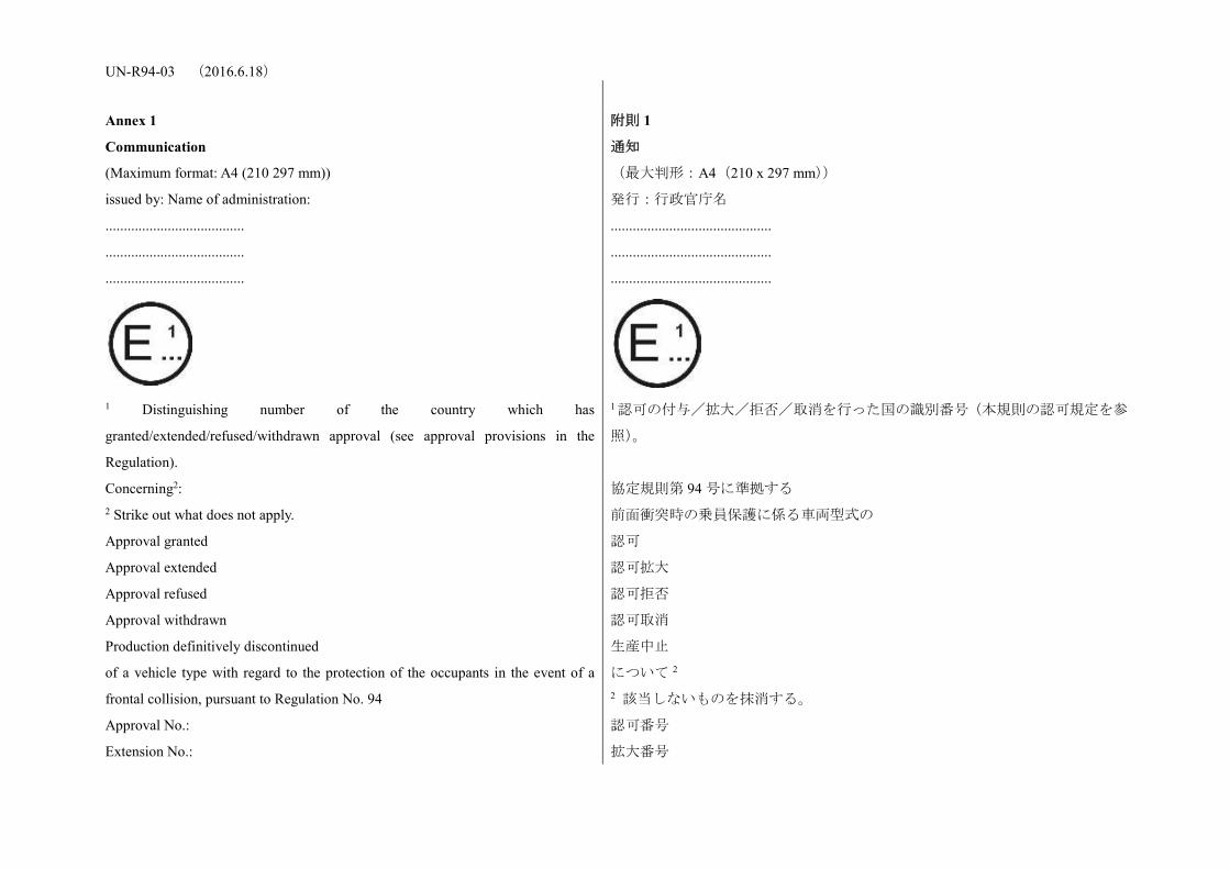
1 Distinguishing number of the country which has
granted/extended/refused/withdrawn approval (see approval provisions in the
Regulation).
1 認可の付与/拡大/拒否/取消を行った国の識別番号(本規則の認可規定を参
照)。
Concerning2: 2 Strike out what does not apply.
Approval granted
Approval extended
Approval refused
Approval withdrawn
Production definitively discontinued
of a vehicle type with regard to the protection of the occupants in the event of a
frontal collision, pursuant to Regulation No. 94
Approval No.:
Extension No.:
協定規則第 94 号に準拠する
前面衝突時の乗員保護に係る車両型式の
認可
認可拡大
認可拒否
認可取消
生産中止
について 2 2 該当しないものを抹消する。
認可番号
拡大番号
UN-R94-03 (2016.6.18) 1. Trade name or mark of the power-driven vehicle 1. 自動車の商品名又は商標
2. Vehicle type 2. 車両型式
3. Manufacturer's name and address 3. メーカーの名称及び所在地
4. If applicable, name and address of manufacturer's representative 4. メーカーの代理人の名称及び所在地(該当する場合)
5. Brief description of the vehicle type as regards its structure, dimensions, lines
and constituent materials
5. 車両型式の構造、寸法、形状及び構成材料の簡単な説明
5.1. Description of the protective system installed in the vehicle 5.1. 車両に取り付けられた保護装置の説明
5.2. Description of interior arrangements or fittings that might affect the tests 5.2. 試験に影響を及ぼす内装部品又は備品の説明
5.3. Location of the electrical power source 5.3. 電源の位置
6. Site of engine: forward/rear/central2 2 Strike out what does not apply.
6. エンジンの位置:前/後/中央 2 2 該当しない項目を抹消する。
7. Drive: front-wheel/rear-wheel2 2 Strike out what does not apply.
7. 駆動:前輪:後輪 2 2 該当しないものを抹消する。
8. Mass of vehicle submitted for testing:
Front axle:
Rear axle:
Total:
8. 試験用に提出された車両の質量
前車軸:
後車軸:
計:
9. Vehicle submitted for approval on 9. 認可用車両の提出日
10. Technical Service responsible for conducting approval tests 10. 認可試験を担当する技術機関
11. Date of report issued by that Service 11. 当該機関による試験成績書発行日
12. Number of report issued by that Service 12. 当該機関が発行した試験成績書番号
13. Approval granted/refused/extended/withdrawn2 2 Strike out what does not apply.
13. 認可/認可拒否/認可拡大/認可取消 2 2 該当しないものを抹消する。
14. Position of approval mark on vehicle 14. 車両上の認可マークの位置
15. Place 15. 場所
16. Date 16. 日付
UN-R94-03 (2016.6.18) 17. Signature 17. 署名
18. The following documents, bearing the approval number shown above, are
annexed to this communication:
(Photographs and/or diagrams and drawings permitting the basic identification of
the type(s) of vehicle and its possible variants which are covered by the approval)
18. 上記の認可番号を付与した下記の書類を本通知に添付する。
(当該車両及び当該認可が適用される派生型の型式の基本的な識別ができる外
観写真及び/又は外観図)
Annex 2
Arrangements of approval marks
附則 2
認可マークの配置
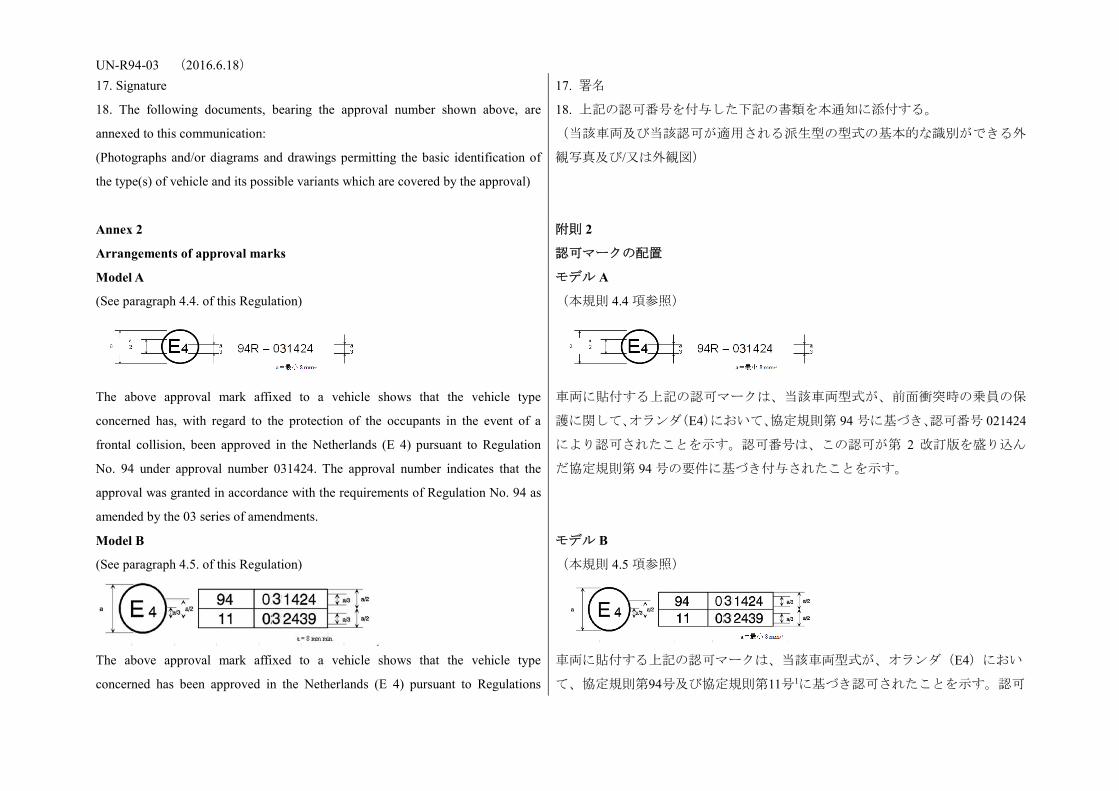
Model A
(See paragraph 4.4. of this Regulation)
The above approval mark affixed to a vehicle shows that the vehicle type
concerned has, with regard to the protection of the occupants in the event of a
frontal collision, been approved in the Netherlands (E 4) pursuant to Regulation
No. 94 under approval number 031424. The approval number indicates that the
approval was granted in accordance with the requirements of Regulation No. 94 as
amended by the 03 series of amendments.
モデル A
(本規則 4.4 項参照)
車両に貼付する上記の認可マークは、当該車両型式が、前面衝突時の乗員の保
護に関して、オランダ(E4)において、協定規則第 94 号に基づき、認可番号 021424
により認可されたことを示す。認可番号は、この認可が第 2 改訂版を盛り込ん
だ協定規則第 94 号の要件に基づき付与されたことを示す。
Model B
(See paragraph 4.5. of this Regulation)
The above approval mark affixed to a vehicle shows that the vehicle type
concerned has been approved in the Netherlands (E 4) pursuant to Regulations
モデル B
(本規則 4.5 項参照)
車両に貼付する上記の認可マークは、当該車両型式が、オランダ(E4)におい
て、協定規則第94号及び協定規則第11号1に基づき認可されたことを示す。認可
UN-R94-03 (2016.6.18) Nos. 94 and 111. The first two digits of the approval numbers indicate that, at the
dates when the respective approvals were granted, Regulation No. 94 incorporated
the 03 series of amendments and Regulation No. 11 incorporated the 03 series of
amendments. 1 The latter number is given only as an example.
番号の最初の2桁は、これらの認可を付与した時点で、協定規則第94号が第3改
訂版を盛り込んでおり、協定規則第11号も第3改訂版を盛り込んでいることを示
す。
1 2 つ目の番号は、単に例として示したものである。
Annex 3
Test procedure
附則 3
試験方法
1. Installation and preparation of the vehicle 1. 試験設備及び試験車両の準備
1.1. Testing ground
The test area shall be large enough to accommodate the run-up track, barrier and
technical installations necessary for the test. The last part of the track, for at least 5
m before the barrier, shall be horizontal, flat and smooth.
1.1. 試験場
試験場は、助走路、バリヤ及び試験に必要な技術設備を収容できるよう十分な
広さを有するものとする。助走路の最後の部分(バリヤの手前)から少なくと
も 5 m の区間は、水平かつ平坦で滑らかな面とする。
1.2. Barrier
The front face of the barrier consists of a deformable structure as defined in Annex
9 of this Regulation. The front face of the deformable structure is perpendicular
within +/- 1 deg. to the direction of travel of the test vehicle. The barrier is secured
to a mass of not less than 7 x 10⁴ kg, the front face of which is vertical within +/- 1
deg. The mass is anchored in the ground or placed on the ground with, if necessary,
additional arresting devices to restrict its movement.
1.2. バリヤ
バリヤの前面は、本規則の附則 9 に定義する可変構造物で構成される。可変構
造物の前面は、試験車両の走行方向に対して±1゜の範囲内で垂直にする。バリ
ヤは 7 x 10⁴ kg 以上の質量に固定し、その前面は±1゜の範囲内で垂直にする。
その質量は地面に固定するか、又は必要な場合にはその動きを抑止するための
追加固定装置を使用して地面に置くこと。
1.3. Orientation of the barrier
The orientation of the barrier is such that the first contact of the vehicle with the
barrier is on the steering-column side. Where there is a choice between carrying out
the test with a right-hand or left-hand drive vehicle, the test shall be carried out
with the less favourable hand of drive as determined by the Technical Service
responsible for the tests.
1.3.バリヤの位置
バリヤの位置は車両との最初の接触がステアリングコラム側で生じるような位
置にする。試験車両について右ハンドルの車両にするか左ハンドルの車両にす
るかを選択できる場合、試験を実施する技術機関が不利と判定する側のハンド
ル位置の車両で試験を実施するものとする。
UN-R94-03 (2016.6.18) 1.3.1. Alignment of the vehicle to the barrier
The vehicle shall overlap the barrier face by 40 per cent +/- 20 mm.
1.3.1.バリヤに対する自動車の直進状態
車両は、バリヤ面と 40%±20 mm 重なり合うものとする。
1.4. State of vehicle 1.4. 車両の状態
1.4.1. General specification
The test vehicle shall be representative of the series production, shall include all
the equipment normally fitted and shall be in normal running order. Some
components may be replaced by equivalent masses where this substitution clearly
has no noticeable effect on the results measured under paragraph 6.
It shall be allowed by agreement between manufacturer and Technical Service to
modify the fuel system so that an appropriate amount of fuel can be used to run the
engine or the electrical energy conversion system.
1.4.1. 一般仕様
試験車両は、申請する車両形式を代表するものであって、通常装備される装置
を全て備え、かつ通常の走行が可能な状態とする。構成部品の一部は、6 項に基
づいて測定される結果に顕著な影響を及ぼさないことが明らかであれば、同等
質量の代用品に替えることができる。
メーカーと技術機関の合意により、エンジン又は電気エネルギー変換システム
を駆動するために適切な量の燃料が使用できるよう燃料システムの修正が認め
られるものとする。
1.4.2. Mass of vehicle 1.4.2. 車両の質量
1.4.2.1. For the test, the mass of the vehicle submitted shall be the unladen kerb
mass.
1.4.2.1. 試験に供する車両の質量は非積載質量とする。
1.4.2.2. The fuel tank shall be filled with water to mass equal to 90 per cent of the
mass of a full load of fuel as specified by the manufacturer with a tolerance of +/- 1
per cent.
This requirement does not apply to hydrogen fuel tanks.
1.4.2.2. 燃料タンクには、メーカーが定める燃料を完全に搭載した場合の質量の
90±1%に等しい質量の水を満たすものとする。
本要件は、水素燃料タンクには適用しない。
1.4.2.3. All the other systems (brake, cooling, ...) may be empty in this case, the
mass of the liquids shall be carefully compensated.
1.4.2.3. 他の全てのシステム(ブレーキ、冷却液等)は、本件では空にすること
ができる。その場合には、それらの液類の質量を注意深く補うものとする。
1.4.2.4. If the mass of the measuring apparatus on board the vehicle exceeds the 25
kg allowed, it may be compensated by reductions which have no noticeable effect
on the results measured under paragraph 6. below.
1.4.2.4. 車両に搭載した測定計器の質量が許容された 25kg を超える場合、下記 6
項に基づいて測定される結果に顕著な影響を及ぼさない減量を行って補正する
ことができる。
1.4.2.5. The mass of the measuring apparatus shall not change each axle reference
load by more than 5 per cent, each variation not exceeding 20 kg.
1.4.2.5. 測定計器の質量は、各車軸の基準荷重に 5%を超える変化をもたらさな
いものとし、それぞれ変動は 20kg を超えてはならない。
1.4.2.6. The mass of the vehicle resulting from the provisions of paragraph 1.4.2.1. 1.4.2.6. 上記 1.4.2.1 項の規定による車両質量を試験成績書に記載するものとす

UN-R94-03 (2016.6.18) above shall be indicated in the report. る。
1.4.3. Passenger compartment adjustments 1.4.3. 車室の調整
1.4.3.1. Position of steering wheel
The steering wheel, if adjustable, shall be placed in the normal position indicated
by the manufacturer or, in the absence of any particular recommendation by the
manufacturer, midway between the limits of its range(s) of adjustment. At the end
of propelled travel, the steering wheel shall be left free, with its spokes in the
position which according to the manufacturer corresponds to straight-ahead travel
of the vehicle.
4.3.1. ステアリングホイールの位置
ステアリングホイールが調節できる場合には、メーカーが指定した通常位置に
設定するか、又は指定がない場合は調整範囲の両端の中間位置に設定するもの
とする。推進移動の最後の時点で、スポークをメーカーが車両の直進に対応す
ると指定した位置に置き、ステアリングホイールを固定しないものとする。
1.4.3.2. Glazing
The movable glazing of the vehicle shall be in the closed position. For test
measurement purposes and in agreement with the manufacturer, it may be lowered,
provided that the position of the operating handle corresponds to the closed
position.
1.4.3.2. 窓ガラス
車両の移動可能なグレイジングは閉じた状態にするものとする。ただし、計測
のためにメーカーが同意した場合、グレイジングを開放してもよい。この場合、
操作ハンドルの位置はグレイジングを閉じた状態の位置とする。
1.4.3.3. Gear-change lever
The gear-change lever shall be in the neutral position. If the vehicle is propelled by
its own engine, then the gear-change level shall be defined by the manufacturer.
1.4.3.3. 変速装置
変速装置は中立位置に設定するものとする。車両がそのエンジンで推進されて
いる場合、ギアチェンジのレベルはメーカーが定めるものとする。
1.4.3.4. Pedals
The pedals shall be in their normal position of rest. If adjustable, they shall be set
in their mid-position unless another position is specified by the manufacturer.
1.4.3.4. ペダル
ペダルは踏み込まれていない通常位置にあるものとする。ペダルが調整可能な
場合には、メーカーが別の位置を指定した場合を除き、ペダルを中間位置に設
定するものとする。
1.4.3.5. Doors
The doors shall be closed but not locked.
1.4.3.5. 扉
扉は閉じるものとする。ただし施錠してはならない。
1.4.3.5.1. In the case of vehicles equipped with an automatically activated door
locking system, the system shall be activated at the start of propulsion of the
vehicle in order to lock the doors automatically before the moment of impact. At
1.4.3.5.1. 自動ドアロックシステムが装備された車両の場合、衝突の瞬間の前に
自動的にドアをロックするために、車両の推進開始時に当該システムを作動さ
せるものとする。メーカーの選択により、車両の推進開始前に手動でドアをロ

UN-R94-03 (2016.6.18) the choice of the manufacturer, the doors shall be locked manually before the start
of propulsion of the vehicle.
ックするものとする。
1.4.3.5.2. In the case of vehicles equipped with an automatically activated door
locking system that is installed optionally and/or which can be de-activated by the
driver, one of the following two procedures shall be used at the choice of the
manufacturer:
1.4.3.5.2. オプション装備として取り付けるおよび/または運転者によって不作
動にすることができる自動ドアロックシステムが装備された車両の場合、メー
カーの選択により、以下の 2 つのテスト手順のいずれかを用いるものとする:
1.4.3.5.2.1. The system shall be activated at the start of propulsion of the vehicle in
order to lock the doors automatically before the moment of impact. At the choice
of the manufacturer, the doors shall be locked manually before the start of
propulsion of the vehicle.
1.4.3.5.2.1. 衝突の瞬間の前に自動的にドアをロックするために、車両の推進開
始時に当該システムを作動させるものとする。メーカーの選択により、車両の
推進開始前に手動でドアをロックするものとする。
1.4.3.5.2.2. The side doors on the impacted side shall be unlocked and the system
overridden for these doors; for the side doors on the non-impacted side, the system
may be activated in order to lock these doors automatically before the moment of
impact. At the choice of the manufacturer, these doors shall be locked manually
before the start of propulsion of the vehicle.
1.4.3.5.2.2. 衝突を受ける側にあるサイドドアのロックは解除し、これらのドア
に関しては当該システムを無効にするものとする。衝突を受けない側にあるサ
イドドアについては、衝突の瞬間の前にこれらのドアを自動的にロックするた
めに当該システムを作動させてもよい。メーカーの選択により、車両の推進開
始前に手動でこれらのドアをロックするものとする。
1.4.3.6. Opening roof
If an opening or removable roof is fitted, it shall be in place and in the closed
position. For test measurement purposes and in agreement with the manufacturer, it
may be open.
1.4.3.6. オープンルーフ
オープンルーフ又は脱着式ルーフが備えられている場合、それらを取り付け、
ルーフが閉じた状態とするものとする。計測のために、メーカーが同意した場
合は、開放状態にすることができる。
1.4.3.7. Sun-visor
The sun-visors shall be in the stowed position.
1.4.3.7. サンバイザ
サンバイザは格納位置に置くものとする。
1.4.3.8. Rear-view mirror
The interior rear-view mirror shall be in the normal position of use.
1.4.3.8. 車室内後写鏡
車室内後写鏡は、通常の使用位置に置くものとする。
1.4.3.9. Arm-rests
Arm-rests at the front and rear, if movable, shall be in the lowered position, unless
this is prevented by the position of the dummies in the vehicles.
1.4.3.9. 肘かけ
前部又は後部の肘かけの位置が調整できる場合は、最も低い位置とする。ただ
し、車内のダミーの位置で妨げられる場合はこの限りではない。
UN-R94-03 (2016.6.18) 1.4.3.10. Head restraints
Head restraints adjustable for height shall be in their appropriate position as
defined by the manufacturer. In the absence of any particular recommendation
from the manufacturer, then the head restraints shall be in their uppermost position.
1.4.3.10. 頭部後傾抑止装置
高さの調節ができる頭部後傾抑止装置は、メーカーが定める適切な位置にする
ものとする。メーカーからの具体的な推奨がない場合は、最も高い位置に設定
するものとする。
1.4.3.11. Seats 1.4.3.11. 座席
1.4.3.11.1. Position of front seats
Seats adjustable longitudinally shall be placed so that their "H" point, determined
in accordance with the procedure set out in Annex 6 is in the middle position of
travel or in the nearest locking position thereto, and at the height position defined
by the manufacturer (if independently adjustable for height). In the case of a bench
seat, the reference shall be to the "H" point of the driver's place.
1.4.3.11.1. 前部座席の位置
前後方向に調節可能な座席は、附則 6 に定める手順に従い決定された各座席の
「H」点が、調節可能な範囲の中間位置又はそれに最も近い固定位置となるよう
設定する。また、高さの調節が独立してできる場合は、メーカーの指定位置に
設定するものとする。ベンチシートの場合は、運転者の位置の「H」点を基準と
するものとする。
1.4.3.11.2. Position of the front seat-backs
If adjustable, the seat-backs shall be adjusted so that the resulting inclination of the
torso of the dummy is as close as possible to that recommended by the
manufacturer for normal use or, in the absence of any particular recommendation
by the manufacturer, to 25 deg. towards the rear from the vertical.
1.4.3.11.2. 前部座席背面の位置
座席背もたれの位置が調節できる場合、ダミーの胴部の傾斜が、通常運転時と
してメーカーが推奨した傾斜角度に可能な限り近付くように調節するものと
し、メーカーの特別の推奨がない場合は垂直位置から後方へ 25°傾斜させる。
1.4.3.11.3. Rear seats
If adjustable, the rear seats or rear bench seats shall be placed in the rearmost
position.
1.4.3.11.2. 後部座席
後部座席又はベンチシートの位置が調節できる場合、最も後ろの位置に調節す
るものとする。
1.4.4. Electrical power train adjustment 1.4.4. 電動パワートレーンの調整
1.4.4.1. The REESS shall be at any state of charge, which allows the normal
operation of the power train as recommended by the manufacturer.
1.4.4.1. REESS は、メーカーが推奨する電動パワートレーンの正常な運転が可能
な、充電状態にするものとする。
1.4.4.2. The electrical power train shall be energized with or without the operation
of the original electrical energy sources (e.g. engine-generator, REESS or electric
energy conversion system), however:
1.4.4.2. オリジナル装備の電源(例:エンジン発電機、REESS 又は電気エネルギ
ー変換システム)の作動の有無を問わず、電動パワートレーンへの通電は行わ
れるものとする。ただし、以下を条件とする。
1.4.4.2.1. By the agreement between Technical Service and manufacturer it shall be 1.4.4.2.1. 技術機関とメーカーが合意した場合には、試験結果に悪影響がない限
UN-R94-03 (2016.6.18) permissible to perform the test with all or parts of the electrical power train not
being energized insofar as there is no negative influence on the test result. For parts
of the electrical power train not energized, the protection against electrical shock
shall be proved by either physical protection or isolation resistance and appropriate
additional evidence.
り、電動パワートレーンの全部又は一部に通電せずに試験を実施することが認
められるものとする。通電しない電動パワートレーンの部分については、物理
的保護若しくは絶縁抵抗のいずれか並びに適切な追加の証拠によって、感電に
対する保護を証明するものとする。
1.4.4.2.2. In the case where an automatic disconnect is provided, at the request of
the manufacturer it shall be permissible to perform the test with the automatic
disconnect being triggered. In this case it shall be demonstrated that the automatic
disconnect would have operated during the impact test. This includes the automatic
activation signal as well as the galvanic separation considering the conditions as
seen during the impact.
1.4.4.2.2. 自動遮断装置を備える場合には、メーカーの要請があれば、自動遮断
装置を作動させた状態で試験を実施することが認められるものとする。この場
合、衝突試験中に自動遮断装置が機能したであろうとの証明になるものとする。
これには、衝突試験中に観察された条件を考慮の上、自動作動信号及び電気分
離の機能に関する証明も含まれる。
2. Dummies 2. ダミー
2.1. Front seats 2.1. 前部座席
2.1.1. A dummy corresponding to the specifications for Hybrid III fiftieth
percentile male dummy1 fitted with a 45° ankle and meeting the specifications for
its adjustment shall be installed in each of the front outboard seats in accordance
with the conditions set out in Annex 5. The ankle of the dummy shall be certified in
accordance with the procedures in Annex 10. 1 The technical specifications and detailed drawings of Hybrid III, corresponding to
the principal dimensions of a fiftieth percentile male of the United States of
America, and the specifications for its adjustment for this test are deposited with
the Secretary-General of the United Nations and may be consulted on request at the
secretariat of the Economic Commission for Europe, Palais des Nations, Geneva,
Switzerland.
2.1.1. ダミーは、45゜の足関節部を取り付けた HYBRID III50 パーセンタイル男
性 1の仕様に対応したダミーとし、その調整に関する仕様を満たすダミーを、附
則 5 に定める条件に基づいて各前列外側席に搭載するものとする。ダミーの足
関節部は附則 10 で規定する手順に基づき確認するものとする。
1 米国の 1/50 パーセンタイル男性の主要寸法に一致する Hybrid III の技術仕様、
詳細な外観図及び本試験のための当該ダミーの調整仕様は、国連事務総長に供
託されており、必要に応じスイス、ジュネーブのパレ・デ・ナシオンの欧州経
済委員会事務局に尋ねることができる。
2.1.2. The car will be tested with restraint systems, as provided by the
manufacturer.
2.1.2. 車両は、メーカーが提供する拘束装置を備えて試験を実施する。
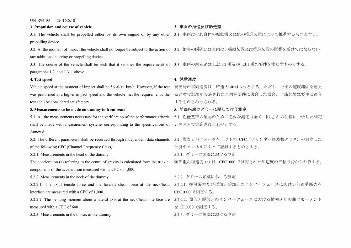
UN-R94-03 (2016.6.18) 3. Propulsion and course of vehicle 3. 車両の推進及び助走路
3.1. The vehicle shall be propelled either by its own engine or by any other
propelling device.
3.1. 車両はそれ自体の原動機又は他の推進装置によって推進するものとする。
3.2. At the moment of impact the vehicle shall no longer be subject to the action of
any additional steering or propelling device.
3.2. 衝突の瞬間には車両は、操縦装置又は推進装置の影響を受けてはならない。
3.3. The course of the vehicle shall be such that it satisfies the requirements of
paragraphs 1.2. and 1.3.1. above.
3.3. 車両の助走路は上記 1.2 項及び 1.3.1 項の要件を満たすものとする。
4. Test speed
Vehicle speed at the moment of impact shall be 56 -0/+1 km/h. However, if the test
was performed at a higher impact speed and the vehicle met the requirements, the
test shall be considered satisfactory.
4. 試験速度
衝突時の車両速度は、時速 56-0/+1 km とする。ただし、上記の速度範囲を超え
る速度で試験が実施された車両が要件に適合した場合、当該試験は要件に適合
するものとみなされる。
5. Measurements to be made on dummy in front seats 5. 前部座席のダミーに関して行う測定
5.1. All the measurements necessary for the verification of the performance criteria
shall be made with measurement systems corresponding to the specifications of
Annex 8.
5.1. 性能基準の確認のために必要な測定は全て、附則 8 の仕様に一致した測定
システムで実施されるものとする。
5.2. The different parameters shall be recorded through independent data channels
of the following CFC (Channel Frequency Class):
5.2. 異なるパラメータを、以下の CFC(チャンネル周波数クラス)の独立した
計測チャンネルによって記録するものとする。
5.2.1. Measurements in the head of the dummy
The acceleration (a) referring to the centre of gravity is calculated from the triaxial
components of the acceleration measured with a CFC of 1,000.
5.2.1. ダミーの頭部における測定
頭部重心加速度(a)は、CFC1000 で測定された加速度の三軸成分から計算する。
5.2.2. Measurements in the neck of the dummy 5.2.2. ダミーの頚部における測定
5.2.2.1. The axial tensile force and the fore/aft shear force at the neck/head
interface are measured with a CFC of 1,000.
5.2.2.1. 軸引張力及び頚部と頭部とのインターフェースにおける前後剪断力を
CFC1000 で測定する。
5.2.2.2. The bending moment about a lateral axis at the neck/head interface are
measured with a CFC of 600.
5.2.2.2. 頚部と頭部とのインターフェースにおける横軸廻りの曲げモーメント
を CFC600 で測定する。
5.2.3. Measurements in the thorax of the dummy 5.2.3. ダミーの胸部における測定

UN-R94-03 (2016.6.18) The chest deflection between the sternum and the spine is measured with a CFC of
180.
胸骨と脊柱の間の胸部のたわみを CFC180 で測定する。
5.2.4. Measurements in the femur and tibia of the dummy 5.2.4. ダミーの大腿骨及び脛骨における測定
5.2.4.1. The axial compressive force and the bending moments are measured with a
CFC of 600.
5.2.4.1.軸圧縮力と曲げモーメントを CFC600 で測定する。
5.2.4.2. The displacement of the tibia with respect to the femur is measured at the
knee sliding joint with a CFC of 180.
5.2.4.2. 大腿骨に対する脛骨の変位を膝部スライド関節において、CFC180 で測
定する。
6. Measurements to be made on the vehicle 6. 車両に関して行う測定
6.1. To enable the simplified test described in Annex 7 to be carried out, the
deceleration time history of the structure shall be determined on the basis of the
value of the longitudinal accelerometers at the base of the "B" pillar on the struck
side of the vehicle with a CFC of 180 by means of data channels corresponding to
the requirements set out in Annex 8;
6.1. 附則 7 に定める簡略試験を実施する場合、附則 8 に規定された要件に適合
する計測チャンネルによって、車両の衝突側の「B」ピラーベース部の前後方向
加速度を CFC180 で計測した値を基として、車体の減速度曲線を決定するもの
とする。
6.2. The speed time history which will be used in the test procedure described in
Annex 7 shall be obtained from the longitudinal accelerometer at the "B" pillar on
the struck side.
6.2. 附則 7 に定める試験手順で用いられる速度の時間経過は、衝突側の「B」ピ
ラーの前後方向の加速度計から得るものとする。
Annex 4
Head Performance Criterion (HPC) and 3 ms head acceleration Performance criteria
附則 4
頭部性能基準(HPC)及び 3 ms の頭部加速度性能基準
1. Head Performance Criterion (HPC36) 1. 頭部性能基準(HPC36)
1.1. The Head Performance Criterion (HPC36) is considered to be satisfied when,
during the test, there is no contact between the head and any vehicle component.
1.1. 頭部性能基準(HPC36)は、試験中に頭部と車両のいずれの構成部品との間
にも接触がない場合、適合したものとみなす。
1.2. If, during the test, there is contact between the head and any vehicle
component, a calculation of HPC is made, on the basis of the acceleration (a),
measured according to paragraph 5.2.1. of Annex 3, by the following expression:
1.2. 試験中に頭部と車両のいずれかの構成部品とが接触する場合、附則3の5.2.1
項に従い測定された加速度(a)を基に、HPC の値を次の式より求める。
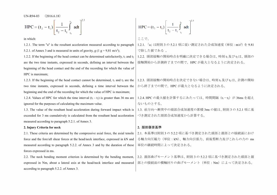
UN-R94-03 (2016.6.18)
in which:
ここで、
1.2.1. The term "a" is the resultant acceleration measured according to paragraph
5.2.1. of Annex 3 and is measured in units of gravity, g (1 g = 9,81 m/s2);
1.2.1. 「a」は附則 3 の 5.2.1 項に従い測定された合成加速度(単位:m/s2)を 9.81
で除した値である 。
1.2.2. If the beginning of the head contact can be determined satisfactorily, t1 and t2
are the two time instants, expressed in seconds, defining an interval between the
beginning of the head contact and the end of the recording for which the value of
HPC is maximum;
1.2.2. 頭部接触の開始時点を明確に決定できる場合は、時刻 t1 及び t2は、頭部の
接触開始から計測終了までの間で、HPC が最大となるように決定される。
1.2.3. If the beginning of the head contact cannot be determined, t1 and t2 are the
two time instants, expressed in seconds, defining a time interval between the
beginning and the end of the recording for which the value of HPC is maximum;
1.2.3. 頭部接触の開始時点を決定できない場合は、時刻 t1及び t2 は、計測の開始
から終了までの間で、HPC が最大となるように決定される。
1.2.4. Values of HPC for which the time interval (t1 - t2) is greater than 36 ms are
ignored for the purposes of calculating the maximum value.
1.2.4. HPC の最大値を計算するにあたっては、時間間隔(t1-t2)が 36ms を超え
ないものとする。
1.3. The value of the resultant head acceleration during forward impact which is
exceeded for 3 ms cumulatively is calculated from the resultant head acceleration
measured according to paragraph 5.2.1. of Annex 3.
1.3. 前方向へ衝突中の頭部合成加速度の累積 3ms の値は、附則 3 の 5.2.1 項に基
づき測定された頭部合成加速度から計算する。
2. Injury Criteria for neck 2. 頚部傷害基準
2.1. These criteria are determined by the compressive axial force, the axial tensile
force and the fore/aft shear forces at the head/neck interface, expressed in kN and
measured according to paragraph 5.2.2. of Annex 3 and by the duration of these
forces expressed in ms.
2.1. 本基準は附則 3 の 5.2.2 項に基づき測定された頭部と頚部との接続面におけ
る軸方向圧縮力(単位:kN)、軸方向引張力、前後剪断力及びこれらの力の ms
単位の継続時間によって決定される。
2.2. The neck bending moment criterion is determined by the bending moment,
expressed in Nm, about a lateral axis at the head/neck interface and measured
according to paragraph 5.2.2. of Annex 3.
2.2. 頚部曲げモーメント基準は、附則 3 の 5.2.2 項に基づき測定された頭部と頚
部との接続面の横軸回りの曲げモーメント(単位:Nm)によって決定される。

UN-R94-03 (2016.6.18) 2.3. The neck flexion bending moment, expressed in Nm, shall be recorded. 2.3. 頚部屈曲曲げモーメントを、Nm を単位として表し記録する。
3. Thorax Compression Criterion (THCC) and Viscous Criterion (V * C) 3. 胸部圧縮基準(THCC)及び胸部粘性基準(V*C)
3.1. The thorax compression criterion is determined by the absolute value of the
thorax deformation, expressed in mm and measured according to paragraph 5.2.3.
of Annex 3.
3.1. 胸部圧縮基準は、附則 3 の 5.2.3 項に基づき測定された胸部変位の絶対値(単
位:mm)によって決定される。
3.2. The viscous criterion (V * C) is calculated as the instantaneous product of the
compression and the rate of deflection of the sternum, measured according to
paragraph 6. of this annex and also paragraph 5.2.3. of Annex 3.
3.2. 胸部粘性基準(V*C)は、本附則の 6.及び附則 3 の 5.2.3 項に基づき測定さ
れた肋骨の圧縮量とたわみ速度の瞬間的な積として計算される。
4. Femur Force Criterion (FFC) 4. 大腿部傷害基準(FFC)
4.1. This criterion is determined by the compression load expressed in kN,
transmitted axially on each femur of the dummy and measured according to
paragraph 5.2.4. of Annex 3 and by the duration of the compressive load expressed
in ms.
4.1. 本基準は附則 3 の 5.2.4 項に基づき測定されたダミーの左右それぞれの軸方
向圧縮荷重(単位:kN)及びこの圧縮荷重の継続時間(単位:ms)によって決
定される。
5. Tibia Compressive Force Criterion (TCFC) and Tibia Index (TI) 5. 脛骨圧縮力基準(TCFC)と脛骨指数(TI)
5.1. The tibia compressive force criterion is determined by the compressive load
(Fz) expressed in kN, transmitted axially on each tibia of the dummy and measured
according to paragraph 5.2.4. of Annex 3.
5.1. 脛骨圧縮力基準は、附則 3 の 5.2.4 項に基づき測定されたダミーの各脛骨の
軸方向に伝達される圧縮荷重(FZ)(単位:kN)によって決定される。
5.2. The tibia index is calculated on the basis of the bending moments (Mx and
My) measured according to paragraph 5.1. by the following expression:
TI = | MR/ (MC) R | + | FZ/ (FC) Z |
Where:
MX = bending moment about the x axis
MY = bending moment about the y axis
(MC)R = critical bending moment and shall be taken to be 225 Nm
FZ = compressive axial force in the z direction
5.2. 脛骨指数は、5.1 項に基づき測定された曲げモーメント(MX と My)に基づ
き、次の式により計算する。
TI = | MR / (MC)R | + | FZ / (FC)Z |
ここで、
MX=x 軸回りの曲げモーメント
MY=y 軸回りの曲げモーメント
(MC)R=臨界曲げモーメントで、225Nm とする。
FZ=z 軸方向の圧縮荷重

UN-R94-03 (2016.6.18) (FC)Z = critical compressive force in the z direction and shall be taken to be 35.9
kN and
The tibia index is calculated for the top and the bottom of each tibia; however, Fz
may be measured at either location. The value obtained is used for the top and
bottom TI calculations. Moments Mx and My are both measured separately at both
locations.
(FC)Z=z 軸方向の臨界圧縮力で、35.9kN とする。
指数は各脛骨の上部と下部の双方で計算される。ただし、FZ は上部と下部のい
ずれか一方で測定することができ、いずれか一方で測定した値を、上部と下部
の双方の TI の計算に使用することができる。Mx と My は両位置で別個に測定
した値を使用する。
6. Procedure for calculating the viscous criteria (V * C) for Hybrid III dummy 6. HYBRID III ダミーの胸部粘性基準(V*C)の計算手順
6.1. The viscous criterion is calculated as the instantaneous product of the
compression and the rate of deflection of the sternum. Both are derived from the
measurement of sternum deflection.
6.1. 胸部粘性基準は、胸骨の圧縮量とたわみ速度の瞬間的な積として計算され
る。肋骨の圧縮量とたわみ速度は、いずれも胸部変位の測定値から得られる。
6.2. The sternum deflection response is filtered once at CFC 180. The compression
at time t is calculated from this filtered signal as:
The sternum deflection velocity at time t is calculated from the filtered deflection
as:
Where D(t) is the deflection at time t in metres and partial t is the time interval in
seconds between the measurements of deflection. The maximum value of partial t
shall be 1.25 x 10⁻⁴ seconds. This calculation procedure is shown diagrammatically
below:
6.2. 胸部変位を CFC180 でフィルターに通し、時間(t)における圧縮量はこの
フィルターを通した信号から次の式により計算する。
時間(t)における肋骨のたわみ速度は、フィルターを通した胸部変位から次式
により計算する。
この場合において、D(t)は時間(t)における変位(単位:m)、∂t は変位測
定の時間間隔(単位:秒)である。∂t の最大値は 1.25 x 10‐4秒とする。この計
算手順を図示すると次の通りである。
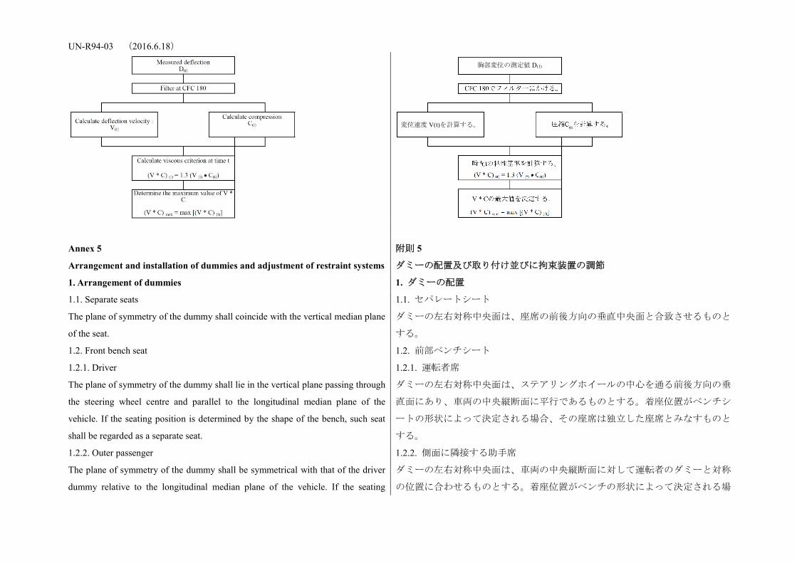
UN-R94-03 (2016.6.18)
Annex 5
Arrangement and installation of dummies and adjustment of restraint systems
附則 5
ダミーの配置及び取り付け並びに拘束装置の調節
1. Arrangement of dummies 1. ダミーの配置
1.1. Separate seats
The plane of symmetry of the dummy shall coincide with the vertical median plane
of the seat.
1.1. セパレートシート
ダミーの左右対称中央面は、座席の前後方向の垂直中央面と合致させるものと
する。
1.2. Front bench seat 1.2. 前部ベンチシート
1.2.1. Driver
The plane of symmetry of the dummy shall lie in the vertical plane passing through
the steering wheel centre and parallel to the longitudinal median plane of the
vehicle. If the seating position is determined by the shape of the bench, such seat
shall be regarded as a separate seat.
1.2.1. 運転者席
ダミーの左右対称中央面は、ステアリングホイールの中心を通る前後方向の垂
直面にあり、車両の中央縦断面に平行であるものとする。着座位置がベンチシ
ートの形状によって決定される場合、その座席は独立した座席とみなすものと
する。
1.2.2. Outer passenger
The plane of symmetry of the dummy shall be symmetrical with that of the driver
dummy relative to the longitudinal median plane of the vehicle. If the seating
1.2.2. 側面に隣接する助手席
ダミーの左右対称中央面は、車両の中央縦断面に対して運転者のダミーと対称
の位置に合わせるものとする。着座位置がベンチの形状によって決定される場
胸部変位の測定値 D(1)
変位速度 V(t)を計算する。
UN-R94-03 (2016.6.18) position is determined by the shape of the bench, such seat shall be regarded as a
separate seat.
合、その座席は独立した座席とみなすものとする。
1.3. Bench seat for front passengers (not including driver)
The planes of symmetry of the dummy shall coincide with the median planes of the
seating positions defined by the manufacturer.
1.3. 前部助手席用ベンチシート(運転者席を除く)
ダミーの左右対称中央面は、メーカーが指定する着座位置の中央面に合致させ
るものとする。
2. Installation of dummies 2. ダミーの取り付け
2.1. Head
The transverse instrumentation platform of the head shall be horizontal within 2.5
deg. To level the head of the test dummy in vehicles with upright seats with
non-adjustable backs, the following sequences must be followed. First adjust the
position of the "H" point within the limits set forth in paragraph 2.4.3.1. below to
level the transverse instrumentation platform of the head of the test dummy. If the
transverse instrumentation platform of the head is still not level, then adjust the
pelvic angle of the test dummy within the limits provided in paragraph 2.4.3.2.
below. If the transverse instrumentation platform of the head is still not level, then
adjust the neck bracket of the test dummy the minimum amount necessary to
ensure that the transverse instrumentation platform of the head is horizontal within
2.5 deg.
2.1. 頭部
頭部の計装プラットホームは水平に対し±2.5°以内となるものとする。座席背
面が調整できない直立型座席を装備した車両において試験ダミーの頭部を水平
にするには、次の手順に従わなければならない。まず、「H」点を下記 2.4.3.1 項
に定める制限値内で調節し、試験ダミーの頭部の計装プラットホームを水平に
調整する。このとき頭部の計装プラットホームが水平にならない場合、下記
2.4.3.2 項に定める制限値内で試験ダミーの骨盤角度を調整する。この再調整を
行っても頭部の計装プラットホームが水平にならない場合、頭部の計装プラッ
トホームを水平に対し±2.5°以内にするため、試験ダミーの首のブラケットを
必要最低限の範囲において調整する。
2.2. Arms 2.2. 腕
2.2.1. The driver's upper arms shall be adjacent to the torso with the centrelines as
close to a vertical plane as possible.
2.2.1. 運転者席に搭載する試験ダミーの上腕は、その中央線をできる限り垂直面
に近付けた状態で、胴部に近付けるものとする。
2.2.2. The passenger's upper arms shall be in contact with the seat back and the
sides of the torso.
2.2.2. 助手席に搭載する試験ダミーの上腕は、座席背もたれ及び胴部側面と接触
させるものとする。
2.3. Hands 2.3. 手
2.3.1. The palms of the driver test dummy shall be in contact with the outer part of
the steering wheel rim at the rim's horizontal centreline. The thumbs shall be over
2.3.1. 運転者席に搭載する試験ダミーの手の平は、ステアリングホイールリムの
外側部分と、ステアリングホイールリムの水平中心線で接触させるものとする。
UN-R94-03 (2016.6.18) the steering wheel rim and shall be lightly taped to the steering wheel rim so that if
the hand of the test dummy is pushed upward by a force of not less than 9 N and
not more than 22 N, the tape shall release the hand from the steering wheel rim.
親指は、ステアリングホイールリムを超えてかけ、試験ダミーの手が 9N以上
22N以下の荷重で上方に押された場合にステアリングホイールリムから手が離
れるように軽くテーピングする。
2.3.2. The palms of the passenger test dummy shall be in contact with outside of
thigh. The little finger shall be in contact with the seat cushion.
2.3.2. 助手席に搭載する試験ダミーの手の平は、大腿部の外側と接触させるもの
とする。小指はシートクッションと接触させるものとする。
2.4. Torso 2.4. 胴部
2.4.1. In vehicles equipped with bench seats, the upper torso of the driver and
passenger test dummies shall rest against the seat back. The midsagittal plane of
the driver dummy shall be vertical and parallel to the vehicle's longitudinal
centreline, and pass through the centre of the steering wheel rim. The midsagittal
plane of the passenger dummy shall be vertical and parallel to the vehicle's
longitudinal centreline and the same distance from the vehicle's longitudinal
centreline as the midsagittal plane of the driver dummy
2.4.1. ベンチシートを装備した車両では、運転者席及び助手席に搭載する試験ダ
ミーの上胴部は、座席背もたれに寄りかかるものとする。運転者席の試験ダミ
ーの胴部中央面は垂直で、車両の縦中央線に平行で、かつステアリングホイー
ルリムの中央を通るものとする。助手席の試験ダミーの胴部中央面は、垂直で、
車両の縦中央線に平行で、かつ車両の縦中央線から運転者席の試験ダミーの中
央対称面までと同一の距離とする。
2.4.2. In vehicles equipped with individual seats, the upper torso of the driver and
passenger test dummies shall rest against the seat back. The midsagittal plane of
the driver and the passenger dummy shall be vertical and shall coincide with the
longitudinal centreline of the individual seat.
2.4.2. 一人掛け座席を装備した車両では、運転者席及び助手席の試験ダミーの上
胴部は座席背もたれに寄りかかるものとする。運転者席及び助手席の試験ダミ
ーの胴部中央面は垂直で、一人掛け座席の縦中心線に合致させるものとする。
2.4.3. Lower torso 2.4.3. 下胴部
2.4.3.1. "H" point
The "H" point of the driver and passenger test dummies shall coincide within 13
mm in the vertical dimension and 13 mm in the horizontal dimension, with a point
6 mm below the position of the "H" point determined using the procedure
described in Annex 6 except that the length of the lower leg and thigh segments of
the "H" point machine shall be adjusted to 414 and 401 mm, instead of 417 and
432 mm respectively.
2.4.3.1. 「H」点
運転者席及び助手席の試験ダミーの「H」点は、附則 6 に示す手順を使用して決
定された「H」点の位置の 6 mm 下の点から垂直方向に 13 mm、水平方向に 13 mm
以内の範囲に合わせるものとする。ただし、「H」点測定装置の下肢部分と大腿
部分の長さは、それぞれ 414 mm 及び 401 mm(417 mm 及び 432 mm ではない)
に調整するものとする。
2.4.3.2. Pelvic angle 2.4.3.2. 骨盤角
UN-R94-03 (2016.6.18) As determined using the pelvic angle gauge (GM) drawing 78051-532 incorporated
by reference in Part 572 which is inserted into the "H" point gauging hole of the
dummy, the angle measured from the horizontal on the 76.2 mm (3 inch) flat
surface of the gauge shall be 22.5 degrees plus or minus 2.5 degrees.
Part572 に援用された骨盤角度ゲージ(GM)(外観図 78051−532)を試験ダミー
の「H」点測定穴に挿入して決定される角度は、ゲージの 76.2 mm(3 インチ)
の表面で測定して水平面から 22.5°±2.5°にあるものとする。
2.5. Legs
The upper legs of the driver and passenger test dummies shall rest against the seat
cushion to the extent permitted by placement of the feet. The initial distance
between the outboard knee clevis flange surfaces shall be 270 mm +/- 10 mm. To
the extent practicable, the left leg of the driver dummy and both legs of the
passenger dummy shall be in vertical longitudinal planes. To the extent practicable,
the right leg of the driver dummy shall be in a vertical plane. Final adjustment to
accommodate placement of feet in accordance with paragraph 2.6. for various
passenger compartment configurations is permitted.
2.5. 脚部
運転者席及び助手席の試験ダミーの上脚は、足の配置が可能な範囲でシートク
ッションにもたれかけるものとする。ニークレビスフランジ外側間の初期間隔
は 270 mm±10 mm とする。運転者席の試験ダミーの左足及び助手席の試験ダミ
ーの両足は、実施可能な範囲で、縦方向垂直に置くものとする。運転者ダミー
の右足は、実施可能な範囲で、垂直面に置くものとする。この場合、様々な車
室形状に対し、2.6 項に従って足を配置するための最終調整を行うことが認めら
れる。
2.6. Feet 2.6. 足
2.6.1.
The right foot of the driver test dummy shall rest on the undepressed accelerator
with the rearmost point of the heel on the floor surface in the plane of the pedal. If
the foot cannot be placed on the accelerator pedal, it shall be positioned
perpendicular to the tibia and placed as far forward as possible in the direction of
the centreline of the pedal with the rearmost point of the heel resting on the floor
surface. The heel of the left foot shall be placed as far forward as possible and shall
rest on the floor pan. The left foot shall be positioned as flat as possible on the toe
board. The longitudinal centreline of the left foot shall be placed as parallel as
possible to the longitudinal centreline of the vehicle. For vehicles equipped with a
footrest, it shall be possible at the request of the manufacturer to place the left foot
on the footrest. In this case the position of the left foot is defined by the footrest
2.6.1. 運転者席の試験ダミーの右足は、踏み込んでいない状態でアクセルペダル
上に置き、踵の最後点をペダル平面上のフロア面に置くものとする。足がアク
セルペダルに置けない場合は、足を脛骨に対して垂直にし、踵の最後点をフロ
ア面に付けたままペダルの中心線の方向に向けて、可能な限り前方に置くもの
とする。左足の踵は可能な限り前方のフロア面に置き、左足はトーボード上に
可能な限り平らにして置くものとする。左足の縦中央線は、車両の縦中央線に
可能な限り平行にするものとする。フットレストを装備した車両については、
メーカーの要請により、左足をフットレストに置くことができるものとする。
この場合、左足の位置はフットレストによって定まる。

UN-R94-03 (2016.6.18) 2.6.2. The heels of both feet of the passenger test dummy shall be placed as far
forward as possible and shall rest on the floor pan. Both feet shall be positioned as
flat as possible on the toe board. The longitudinal centreline of the feet shall be
placed as parallel as possible to the longitudinal centreline of the vehicle.
2.6.2. 助手席の試験ダミーの両足の踵は、可能な限り前方のフロア面に置き、両
足ともにトーボード上に可能な限り平らにして置くものとする。足の縦中央線
は、車両の縦中央線に可能な限り平行にするものとする。
2.7. The measuring instruments installed shall not in any way affect the movement
of the dummy during impact.
2.7. 取り付けられた測定計器は、衝撃時に、ダミーの動きにいかなる影響も与
えてはならない。
2.8. The temperature of the dummy and the system of measuring instruments shall
be stabilized before the test and maintained so far as possible within a range
between 19 °C and 22.2 °C.
2.8. ダミー及び測定計器システムの温度は、試験前に安定させ、可能な限り 19℃
から 22℃の間に維持するものとする。
2.9. Dummy clothing 2.9. ダミーの着衣
2.9.1. The instrumented dummies will be clothed in formfitting cotton stretch
garments with short sleeves and mid-calf length trousers specified in FMVSS 208,
drawings 78051-292 and 293 or their equivalent.
2.9.1. 試験ダミーには、米国連邦自動車安全基準第 208 号の外観図 78051-292 及
び 293 で指定された適正な大きさの木綿の伸縮性生地の半袖の衣服並びにふく
らはぎ中間丈のズボン、又はそれと同等のものを着用させるものとする。
2.9.2. A size 11XW shoe, which meets the configuration size, sole and heel
thickness specifications of the US military standard MIL S 13192, revision P and
whose weight is 0.57 +/- 0.1 kg, shall be placed and fastened on each foot of the
test dummies.
2.9.2. 試験ダミーの左右の足には、サイズ 11XW の靴であって、形状サイズ、靴
底及び踵の厚さが米国軍規格 MIL S 13192、「P」改訂版の仕様に適合し、重さが
0.57±0.1 kg のものを履かせて固定するものとする。
3. Adjustment of restraint system
The dummy jacket shall be installed at the appropriate position where the bolt
hole of the neck lower bracket and the work hole of the dummy jacket are at
the same position. With the test dummy at its designated seating position, as
specified by the appropriate requirements of paragraphs 2.1. to 2.6. and 3.1 to
3.6. above, place the belt around the test dummy and fasten the latch. Remove
all slack from the lap belt. Pull the upper torso webbing out of the retractor
horizontally at a position via the centre of the dummy and allow it to retract.
Repeat this operation four times. The shoulder belt should be at the position
3. 拘束装置の調整
ダミージャケットを、頸部下部ブラケットのボルト穴とダミージャケットのワ
ーク穴が同じ位置になるような適切な位置に取り付けるものとする。試験ダミ
ーを 2.1 項から 2.6 項までで規定する要件で指定の着座位置に置き、試験ダミー
に座席ベルトを締め、ラッチを留め、腰用帯部のたるみは全て除くものとする。
肩用帯部は肩から外れないような領域と頸部に触れないような領域の間に位置
すべきものとする。座席ベルトの経路は以下に位置するものとする:ハイブリ
ッド III 50 パーセンタイル男性ダミーについては、外側のダミージャケットの穴
が座席ベルトによって完全には隠れないものとする。肩用帯部を巻取装置から
UN-R94-03 (2016.6.18) between the area which shall not be taken off from shoulder and shall not
contact with the neck. The seat belt path shall be positioned: for Hybrid III
fiftieth percentile male dummy, the hole of the outer side dummy jacket shall
not be fully hidden by the seat belt. Apply a 9 to 18 N tension load to the lap
belt. If the belt system is equipped with a tension-relieving device, introduce
the maximum amount of slack into the upper torso belt that is recommended by
the manufacturer for normal use in the owner's manual for the vehicle. If the
belt system is not equipped with a tension-relieving device, allow the excess
webbing in the shoulder belt to be retracted by the rewind force of the retractor.
Where the safety belt and safety belt anchorages are located such that the belt does
not lie as required above then the safety belt may be manually adjusted and
retained by tape.
引き出しこれを引っ込ませる。この操作を 4 回繰り返し、肩用帯部はた後、9N
から 18Nの引張荷重を腰用帯部に加える。座席ベルトに張力緩和装置が装備さ
れている場合、オーナーズマニュアルでメーカーが通常運転時に推奨している
最大のたるみ量を肩用帯部に設定する。座席ベルトに張力緩和装置が装備され
ていない場合、肩用帯部の余分なたるみは、巻取装置の引張力で引っ張らせる
ようにする。
座席ベルトおよび座席ベルト取付装置が、上記の要求どおりにベルトを配置す
ることができないような位置にある場合、座席ベルトを手で調節してテープで
保持してもよい。
Annex 6
Procedure for determining the "H" point and the actual torso angle for
seating positions in motor vehicles1
Appendix 1 - Description of the three dimensional "H" point machine (3-D H
machine)1
Appendix 2 - Three-dimensional reference system1
Appendix 3 - Reference data concerning seating positions1
1 The procedure is described in Annex 1 to the Consolidated Resolution on the
Construction of Vehicles (RE.3) (document ECE/TRANS/WP.29/78/Rev.2).
www.unece.org/trans/main/wp29/wp29wgs/wp29gen
/wp29resolutions.html
附則 6
自動車の着座位置の「H」点と実トルソ角の決定方法 1
付録 1− 三次元「H」点測定装置の説明(三次元マネキン)1
付録 2− 三次元座標方式 1
付録 3− 着座位置に関する基準データ 1
1 当該手順は、車両構造統合決議(R.E.3)、文書 ECE/TRANS/WP.29/78/Rev.2
(www.unece.org/trans/main/wp29/wp29wgs/wp29gen/wp29resolutions.html)の附則
1 に定義されている。
UN-R94-03 (2016.6.18) Annex 7
Test procedure with trolley
附則 7
台車を使った試験手順
1. Test installation and procedure 1. 試験設備及び手順
1.1. Trolley
The trolley shall be so constructed that no permanent deformation appears after the
test. It shall be so guided that, during the impact phase, the deviation in the vertical
plane does not exceed 5 deg. and 2 deg. in the horizontal plane.
1.1. 台車
台車は、試験後に恒久的な変形が表れることの無いよう製造されるものとする。
また、台車は衝突時において、垂直面の偏向が 5°を超えず、水平面の偏向が 2°
を超えないように誘導されるものとする。
1.2. State of the structure 1.2. 構造の状態
1.2.1. General
The structure tested shall be representative of the series production of the vehicles
concerned. Some components may be replaced or removed where such
replacement or removal clearly has no effect on the test results.
1.2.1. 一般要件
試験される車体は、生産される型式を代表するものとする。一部の構成部品は、
試験結果に影響がないことが明らかであれば、交換又は取り外しをすることが
できる。
1.2.2. Adjustments
Adjustments shall conform to those set out in paragraph 1.4.3. of Annex 3 to this
Regulation, taking into account what is stated in paragraph 1.2.1. above.
1.2.2. 調整
調整は、附則 3 の 1.4.3 項の規定に適合するように、1.2.1 項の規定を考慮し行わ
れるものとする。
1.3. Attachment of the structure 1.3. 車体の台車への取り付け
1.3.1. The structure shall be firmly attached to the trolley in such a way that no
relative displacement occurs during the test.
1.3.1. 車体は、試験中に相対的移動が生じないように台車に確実に固定されるも
のとする。
1.3.2. The method used to fasten the structure to the trolley shall not have the effect
of strengthening the seat anchorages or restraint devices, or of producing any
abnormal deformation of the structure.
1.3.2. 車体を台車に固定する際は、座席取付装置又は拘束装置が強化されたり、
車体の異常な変形が生じたりしないように行うものとする。
1.3.3. The attachment device recommended is that whereby the structure rests on
supports placed approximately in the axis of the wheels or, if possible, whereby the
structure is secured to the trolley by
the fastenings of the suspension system.
1.3.3. 推奨される取り付け方法は、車体の左右のホイール間に設けられたサポー
ト面に取り付けるか、又は可能であれば車体に懸架装置を取り付けた状態で、
台車に固定する。
1.3.4. The angle between the longitudinal axis of the vehicle and the direction of 1.3.4. 車体の前後方向の中心線と運動方向の間の角度に 2°のずれを許容する。

UN-R94-03 (2016.6.18) motion of the trolley shall be 0 deg. +/- 2 deg.
1.4. Dummies
The dummies and their positioning shall conform to the specifications in Annex 3,
paragraph 2.
1.4. ダミー
ダミー及びその配置は、附則 3 の 2 項の仕様に適合するものとする。
1.5. Measuring apparatus 1.5. 測定計器
1.5.1. Deceleration of the structure
The position of the transducers measuring the deceleration of the structure during
the impact shall be parallel to the longitudinal axis of the trolley according to the
specifications of Annex 8 (CFC 180).
1.5.1. 車体の減速度
衝突試験中の車体の減速度を測定するトランスデューサーの位置は、附則 8 の
仕様(CFC180)に従い、台車の前後方向の中心線に平行にするものとする。
1.5.2. Measurements to be made on the dummies
All the measurements necessary for checking the listed criteria are set out in Annex
3, paragraph 5.
1.5.2. ダミーに関する測定
記載した性能基準を検査するために必要な全ての測定を、附則 3 の 5 項に規定
する。
1.6. Deceleration curve of the structure
The deceleration curve of the structure during the impact phase shall be such that
the "variation of speed in relation to time" curve obtained by integration at no point
differs by more than +/- 1 m/s from the "variation of speed in relation to time"
reference curve of the vehicle concerned as defined in appendix to this annex. A
displacement with regard to the time axis of the reference curve may be used to
obtain the structure velocity inside the corridor.
1.6. 車体の減速度曲線
衝突試験中の車体の減速度曲線を積分して得られた「時間に対する速度変動」
曲線は、いずれの点でも本付録に定められた当該車両の「時間に対する速度変
動」基準曲線から±1m/s を超えて相違してはならない。また、速度曲線を得る
ためには、基準曲線の時間軸に対する変位量から求めてもよい。
1.7. Reference curve deltaV = f(t) of the vehicle concerned
This reference curve is obtained by integration of the deceleration curve of the
vehicle concerned measured in the frontal collision test against a barrier as
provided for in paragraph 6. of Annex 3 to this Regulation.
1.7. 当該車両の基準曲線ΔV=f(t)
この基準曲線は、本規則附則 3 の 6 項に定めるバリヤに対する前面衝突試験で
測定された当該車両の減速度曲線を積分して求めるものとする。
1.8. Equivalent method
The test may be performed by some other method than that of deceleration of a
trolley, provided that such method complies with the requirement concerning the
1.8. 同等の方法
本試験は、上記 1.6 項に規定する速度変動範囲に関する要件に適合する方法であ
れば、台車の減速度を使った方法以外で実施してもよい。

UN-R94-03 (2016.6.18) range of variation of speed described in paragraph 1.6. above.
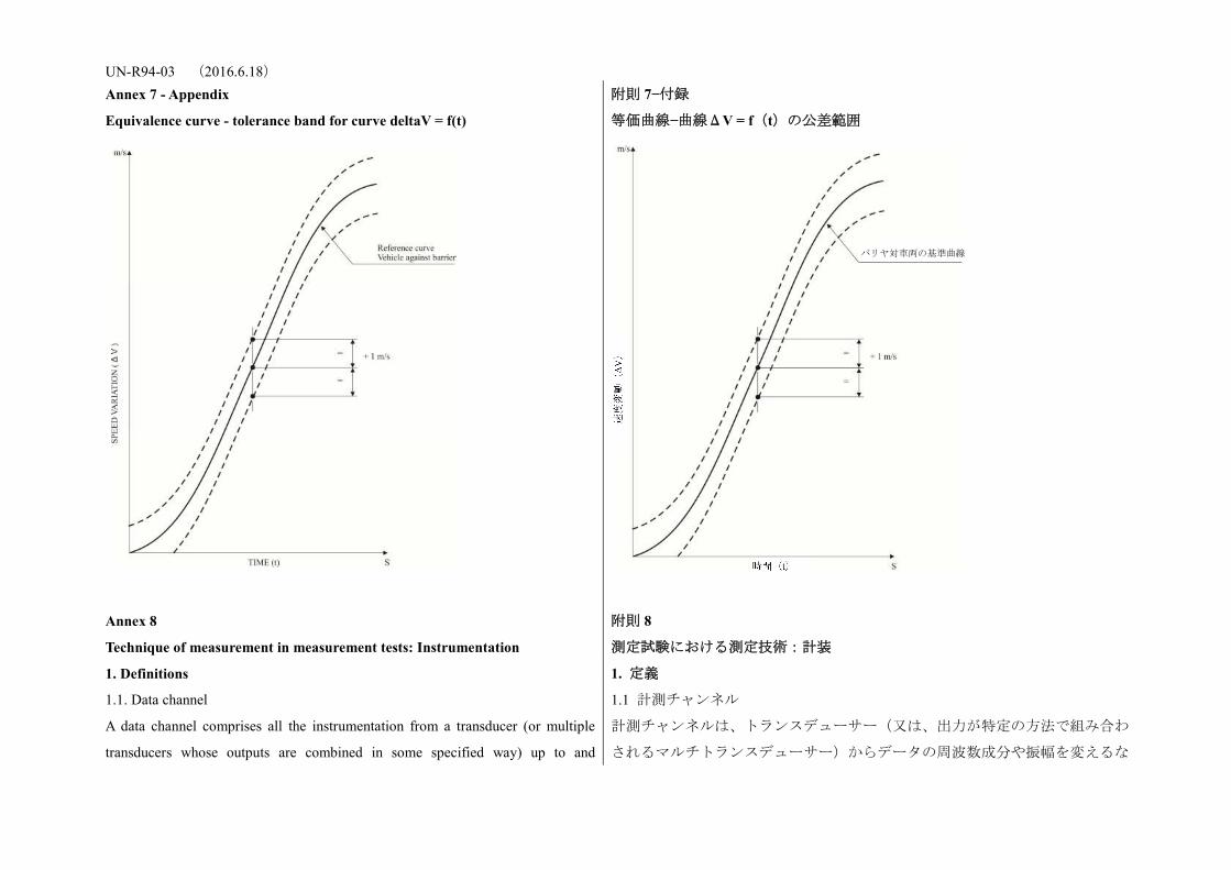
UN-R94-03 (2016.6.18) Annex 7 - Appendix
Equivalence curve - tolerance band for curve deltaV = f(t)
附則 7−付録
等価曲線−曲線ΔV = f(t)の公差範囲
Annex 8
Technique of measurement in measurement tests: Instrumentation
附則 8
測定試験における測定技術:計装
1. Definitions 1. 定義
1.1. Data channel
A data channel comprises all the instrumentation from a transducer (or multiple
transducers whose outputs are combined in some specified way) up to and
1.1 計測チャンネル
計測チャンネルは、トランスデューサー(又は、出力が特定の方法で組み合わ
されるマルチトランスデューサー)からデータの周波数成分や振幅を変えるな
バリヤ対車両の基準曲線
UN-R94-03 (2016.6.18) including any analysis procedures that may alter the frequency content or the
amplitude content of data.
どの分析手段までを含む全ての計装から成る。
1.2. Transducer
The first device in a data channel used to convert a physical quantity to be
measured into a second quantity (such as an electrical voltage) which can be
processed by the remainder of the channel.
1.2. トランスデューサー
計測チャンネルにおいて、測定する物理量を電気信号などの処理可能な二次量
に変換するために用いる最初の装置をいう。
1.3. Channel Amplitude Class: CAC
The designation for a data channel that meets certain amplitude characteristics as
specified in this annex. The CAC number is numerically equal to the upper limit of
the measurement range.
1.3. チャンネル振幅レンジ:CAC
本附則に定めるある振幅特性を満たす計測チャンネルの呼びかたをいう。CAC
の数値は、計測チャンネルの測定範囲の最大値に相当する数値を用いる。
1.4. Characteristic frequencies FH, FL, FN
These frequencies are defined in Figure 1 of this annex.
1.4.周波数特性(FH 、FL 、FN)
これらの周波数は本附則の図 1 に定義する。
1.5. Channels Frequency Class: CFC
The channel frequency class is designated by a number indicating that the channel
frequency response lies within the limits specified in Figure 1 of this annex. This
number and the value of the frequency FH in Hz are numerically equal.
1.5. チャンネル周波数クラス:CFC
チャンネル周波数クラスは、チャンネル周波数反応が本附則の図 1 に定める制
限値内にあることを示す数字で表す。この数字は周波数 FH(Hz)の値で表され
る。
1.6. Sensitivity coefficient
The slope of the straight line representing the best fit to the calibration values
determined by the method of least square within the channel amplitude class.
1.6. 感度係数
CAC 内で最小二乗法によって決定した校正値に最も適合する直線の傾きをい
う。
1.7. Calibration factor of a data channel
The mean value of the sensitivity coefficients evaluated over frequencies which are
evenly spaced on a logarithmic scale between
1.7. 計測チャンネルの校正係数
以下の対数目盛上に等間隔に並ぶ複数の周波数について評価した感度係数の平
均値をいう。
1.8. Linearity error
The ratio, in per cent, of the maximum difference between the calibration value and
1.8. 直線性誤差
校正値と上記 1.6 項で定義された直線上の対応値との差の最大値が、CAC に対

UN-R94-03 (2016.6.18) the corresponding value read on the straight line defined in paragraph 1.6. above at
the upper limit of the channel amplitude class.
して示す割合を%単位で表した比率をいう。
1.9. Cross sensitivity
The ratio of the output signal to the input signal, when an excitation is applied to
the transducer perpendicular to the measurement axis. It is expressed as a
percentage of the sensitivity along the measurement axis.
1.9. 横軸感度
トランスデューサーに対して、計測軸方向に垂直に励起をかけた場合の、入力
信号に対する出力信号の比率をいう。この感度は、計測軸に沿った感度の比率
として示される。
1.10. Phase delay time
The phase delay time of a data channel is equal to the phase delay (in radians) of a
sinusoidal signal, divided by the angular frequency of that signal (in
radians/second).
1.10. 位相遅れ時間
計測チャンネルの位相遅れ時間は、正弦信号の位相遅れ(rad)をその信号の角
速度(rad/s)で除したものをいう。
1.11. Environment
The aggregate, at a given moment, of all external conditions and influences to
which the data channel is subjected.
1.11. 環境
ある瞬間に計測チャンネルが受ける全ての外的条件及び影響をいう。
2. Performance requirements 2. 性能要件
2.1. Linearity error
The absolute value of the linearity error of a data channel at any frequency in the
CFC, shall be equal to or less than 2.5 per cent of the value of the CAC, over the
whole measurement range.
2.1. 直線性誤差
CFC のいずれの周波数においても、計測チャンネルの直線性誤差の絶対値は、
測定範囲全体にわたって CAC の値の 2.5%以下とする。
2.2. Amplitude against frequency
The frequency response of a data channel shall lie within the limiting curves given
in Figure 1 of this annex. The zero dB line is determined by the calibration factor.
2.2. 周波数に対する振幅
計測チャンネルの周波数反応は、本附則の図 1 に示す斜線内とする。ゼロ dB ラ
インは校正係数によって決定される。
2.3. Phase delay time
The phase delay time between the input and the output signals of a data channel
shall be determined and shall not vary by more than 1/10 FH seconds between 0.03
FH and FH.
2.3. 位相遅れ時間
位相遅れ時間は、計測チャンネルの入力信号と出力信号の間で計測されるもの
とし、0.03 FHから FH の間で 1/10 FH 秒以上変動してはならない。
2.4. Time 2.4. 時間
UN-R94-03 (2016.6.18) 2.4.1. Time base
A time base shall be recorded and shall at least give 1/100 s with an accuracy of 1
per cent.
2.4.1. 時間基準
時間基準を少なくとも 0.01 秒間隔で記録し、精度は±1%とする。
2.4.2. Relative time delay
The relative time delay between the signal of two or more data channels, regardless
of their frequency class, must not exceed 1 ms excluding delay caused by phase
shift.
Two or more data channels of which the signals are combined shall have the same
frequency class and shall not have relative time delay greater than 1/10 FH seconds.
This requirement applies to analogue signals as well as to synchronization pulses
and digital signals.
2.4.2. 相対時間遅れ
2 つ以上の計測チャンネルの信号間の相対時間遅れは、CFC に関わらず、位相
変換による位相ずれを除き 0.001 秒(1ms)を超えてはならない。信号が結合して
いる 2 つ以上の計測チャンネルは、同一の CFC を有し、1/10 FH秒以上の相対時
間遅れがあってはならない。なお、この要件は、同期パルスやデジタル信号と
同様に、アナログ信号にも適用する。
2.5. Transducer cross sensitivity
The transducer cross sensitivity shall be less than 5 per cent in any direction.
2.5. トランスデューサーの横軸感度
トランスデューサーの横軸感度は、いずれの方向でも 5%未満とする。
2.6. Calibration 2.6. 校正
2.6.1. General
A data channel shall be calibrated at least once a year against reference equipment
traceable to known standards. The methods used to carry out a comparison with
reference equipment shall not introduce an error greater than 1 per cent of the
CAC. The use of the reference equipment is limited to the frequency range for
which they have been calibrated. Subsystems of a data channel may be evaluated
individually and the results factored into the accuracy of the total data channel.
This can be done for example by an electrical signal of known amplitude
simulating the output signal of the transducer which allows a check to be made on
the gain factor of the data channel, excluding the transducer.
2.6.1. 一般規則
計測チャンネルは、少なくとも年1回は公の基準で確証された標準装置によっ
て校正するものとする。標準装置との比較による方法では、CAC の 1%を超え
る誤差があってはならない。標準装置の使用は、校正された周波数の範囲だけ
とする。計測チャンネルのサブシステムは個々に評価することができるものと
し、その結果を計測チャンネル全体の精度とすることができる。例えば、トラ
ンスデューサーの出力信号をシミュレートする既知の振幅の電気信号を用い、
トランスデューサーを除く計測チャンネルの校正を行うことができる。
2.6.2. Accuracy of reference equipment for calibration
The accuracy of the reference equipment shall be certified or endorsed by an
2.6.2. 校正用標準装置の精度
標準装置の精度は、公認の検定機関により証明又は保証されるものとする。

UN-R94-03 (2016.6.18) official metrology service.
2.6.2.1. Static calibration 2.6.2.1. 静的校正
2.6.2.1.1. Accelerations
The errors shall be less than +/- 1.5 per cent of the channel amplitude class.
2.6.2.1.1. 加速度
誤差はチャンネル振幅レンジの±1.5%未満とする。
2.6.2.1.2. Forces
The error shall be less than +/- 1 per cent of the channel amplitude class.
2.6.2.1.2. 荷重
誤差はチャンネル振幅レンジの±1%未満とする。
2.6.2.1.3. Displacements
The error shall be less than +/- 1 per cent of the channel amplitude class.
2.6.2.1.3. 変位
誤差はチャンネル振幅レンジの±1%未満とする。
2.6.2.2. Dynamic calibration 2.6.2.2. 動的校正
2.6.2.2.1. Accelerations
The error in the reference accelerations expressed as a percentage of the channel
amplitude class shall be less than +/- 1.5 per cent below 400 Hz, less than +/- 2 per
cent between 400 Hz and 900 Hz, and less than +/- 2.5 per cent above 900 Hz.
2.6.2.2.1. 加速度
チャンネル振幅レンジの率で表された基準加速度の誤差は、400 Hz 未満では振
幅レンジの 1.5%未満、400 Hz から 900 Hz までは振幅レンジの 2%未満、900 Hz
超では振幅レンジの 2.5%未満とする。
2.6.2.3. Time
The relative error in the reference time shall be less than 10-5.
2.6.2.3. 時間
基準時間の相対誤差は、10-5 未満とする。
2.6.3. Sensitivity coefficient and linearity error
The sensitivity coefficient and the linearity error shall be determined by measuring
the output signal of the data channel against a known input signal for various
values of this signal. The calibration of the data channel shall cover the whole
range of the amplitude class.
For bi-directional channels, both the positive and negative values shall be used.
If the calibration equipment cannot produce the required input owing to the
excessively high values of the quantity to be measured, calibrations shall be carried
out within the limits of the calibration standards and these limits shall be recorded
in the test report.
2.6.3. 感度係数及び直線性誤差
感度係数及び直線性誤差は、計測チャンネルの出力信号を、当該信号のさまざ
まな値に対する既知の入力信号に対して計測して定めるものとする。計測チャ
ンネルの校正は、CAC 内の全ての範囲をカバーするものとする。
二極性のチャンネルでは、正負両方の値を確認するものとする。
なお、測定量が非常に高いために校正装置から必要な入力が得られない場合、
校正は当該校正装置の限度内で実施し、この場合、その限界値を試験報告書に
記録するものとする。
また、データチャネルは、 の間に含まれる1つ又はある代表の周

UN-R94-03 (2016.6.18) A total data channel shall be calibrated at a frequency or at a spectrum of
frequencies having a significant value between
波数において校正されるものとする。
2.6.4. Calibration of the frequency response
The response curves of phase and amplitude against frequency shall be determined
by measuring the output signals of the data channel in terms of phase and
amplitude against a known input signal, for various values of this signal varying
between FL and 10 times the CFC or 3,000 Hz, whichever is lower.
2.6.4. 周波数反応の校正
周波数に対する位相及び振幅の反応曲線は、FLから CFC の 10 倍又は 3,000 Hz
のいずれか低い方までのいくつかの値について、既知の入力信号に対する位相
と振幅に関する計測チャンネルからの出力信号を測定して決定するものとす
る。
2.7. Environmental effects
A regular check shall be made to identify any environmental influence (such as
electric or magnetic flux, cable velocity, etc.). This can be done for instance by
recording the output of spare channels equipped with dummy transducers. If
significant output signals are obtained corrective action shall be taken, for instance
by replacement of cables.
2.7. 環境の影響
衝撃試験における計測時には、環境の影響(電束又は磁束、ケーブル速度など)
を定期的に点検する。例えば、ダミートランスデューサーを取り付けた予備の
計測チャンネルの出力を記録して行うことができる。万一大きな出力信号が確
認された場合は、ケーブル交換等の補正措置を行うものとする。
2.8. Choice and designation of the data channel
The CAC and CFC define a data channel.
The CAC shall be 1, 2 or 5 to a power of ten.
2.8. 計測チャンネルの選択及び指定
CAC 及び CFC で計測チャンネルを規定する。
CAC は 10 のパワーに対して 1、2 又は 5 とする。
3. Mounting of transducers
Transducers should be rigidly secured so that their recordings are affected by
vibration as little as possible. Any mounting having a lowest resonance frequency
equal to at least 5 times the frequency FH of the data channel considered shall be
considered valid. Acceleration transducers in particular should be mounted in such
a way that the initial angle of the real measurement axis to the corresponding axis
of the reference axis system is not greater than 5 deg. unless an analytical or
experimental assessment of the effect of the mounting on the collected data is
made. When multi-axial accelerations at a point are to be measured, each
3. トランスデューサーの取り付け
トランスデューサーは、記録値が可能な限り振動の影響を受けないよう確実に
固定すべきものとする。検討される計測チャンネルの周波数 FHの 5 倍以上の最
低共振周波数が得られれば、取り付けが有効とみなされるものとする。特に加
速度計は、基準軸システムの対応軸に対する実際の測定軸の当初の角度差が 5°
以内になるよう取り付けるべきものとし、それ以外の場合には、取り付け効果
の分析又は実験評価を収集データに関して行なわなければならない。1 点で複数
軸の加速度を測定する場合、各々の加速度計の軸は測定点から 10 mm 以内、感
度中心は 30 mm 以内にあるべきものとする。
UN-R94-03 (2016.6.18) acceleration transducer axis should pass within 10 mm of that point, and the centre
of seismic mass of each accelerometer should be within 30 mm of that point.
4. Data processing 4. データ処理
4.1. Filtering
Filtering corresponding to the frequencies of the data channel class may be carried
out during either recording or processing of data. However, before recording,
analogical filtering at a higher level than CFC should be effected in order to use at
least 50 per cent of the dynamic range of the recorder and to reduce the risk of high
frequencies saturating the recorder or causing aliasing errors in the digitalizing
process.
4.1. フィルタリング
計測チャンネル周波数クラスに対応したフィルタリングは、記録中又はデータ
処理中のいずれでも行うことができる。ただし、記録装置のダイナミックレン
ジの 50%以上を使用するため、また、記録の高周波飽和やデジタル処理時のエ
リアシングエラーを減らすため、記録に先立って CFC より高いレベルでのアナ
ログフィルタリングを行わなければならない。
4.2. Digitalizing 4.2. デジタル化
4.2.1. Sampling frequency
The sampling frequency should be equal to at least 8 FH. In the case of analogical
recording, when the recording and reading speeds are different, the sampling
frequency can be divided by the speed ratio.
4.2.1. サンプリング周波数
サンプリング周波数は少なくとも FHの 8 倍に等しいものとする。ただし、アナ
ログ記録の際、記録と再生速度が異なるときにはその速度比でサンプリング周
波数を除すことができる。
4.2.2. Amplitude resolution
The size of digital words should be at least 7 bits and a parity bit.
4.2.2. 振幅分解能
デジタルワードの長さは、少なくとも 7 ビットプラス 1 符号とする。
5. Presentation of results
The results should be presented on A4 size paper (ISO/R 216). Results presented as
diagrams should have axes scaled with a measurement unit corresponding to a
suitable multiple of the chosen unit (for example, 1, 2, 5, 10, 20 millimetres). SI
units shall be used, except for vehicle velocity, where km/h may be used, and for
accelerations due to impact where g, with g = 9.8 m/s2, may be used.
5. 結果提出
結果は A4 用紙(ISO/R 216)で提出すべきものとする。図面で提出される結果
は、選択単位の適当な倍数に一致する測定単位で縮尺された軸を有する(例え
ば 1、2、5、10、20 mm)SI 単位を使用するものとする。ただし、車両速度では
km/h を使用でき、また衝突による加速度では g(g = 9.81 m/s2)を使用すること
ができる。
Figure 1: Frequency response curve 図 1:周波数反応曲線
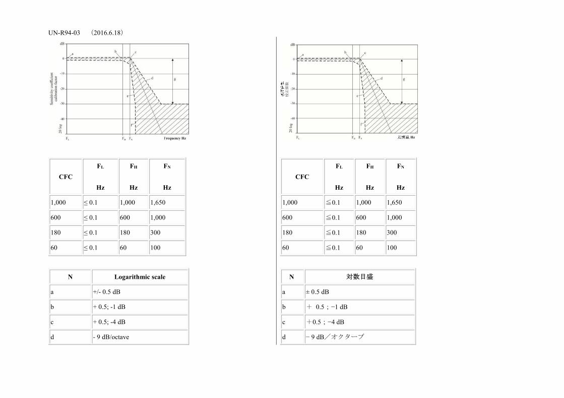
UN-R94-03 (2016.6.18)
CFC FL
Hz
FH
Hz
FN
Hz
1,000 ≤ 0.1 1,000 1,650
600 ≤ 0.1 600 1,000
180 ≤ 0.1 180 300
60 ≤ 0.1 60 100
N Logarithmic scale
a +/- 0.5 dB
b + 0.5; -1 dB
c + 0.5; -4 dB
d - 9 dB/octave
CFC FL
Hz
FH
Hz
FN
Hz
1,000 ≦0.1 1,000 1,650
600 ≦0.1 600 1,000
180 ≦0.1 180 300
60 ≦0.1 60 100
N 対数目盛
a ± 0.5 dB
b + 0.5;−1 dB
c +0.5;−4 dB
d − 9 dB/オクターブ
校正係数
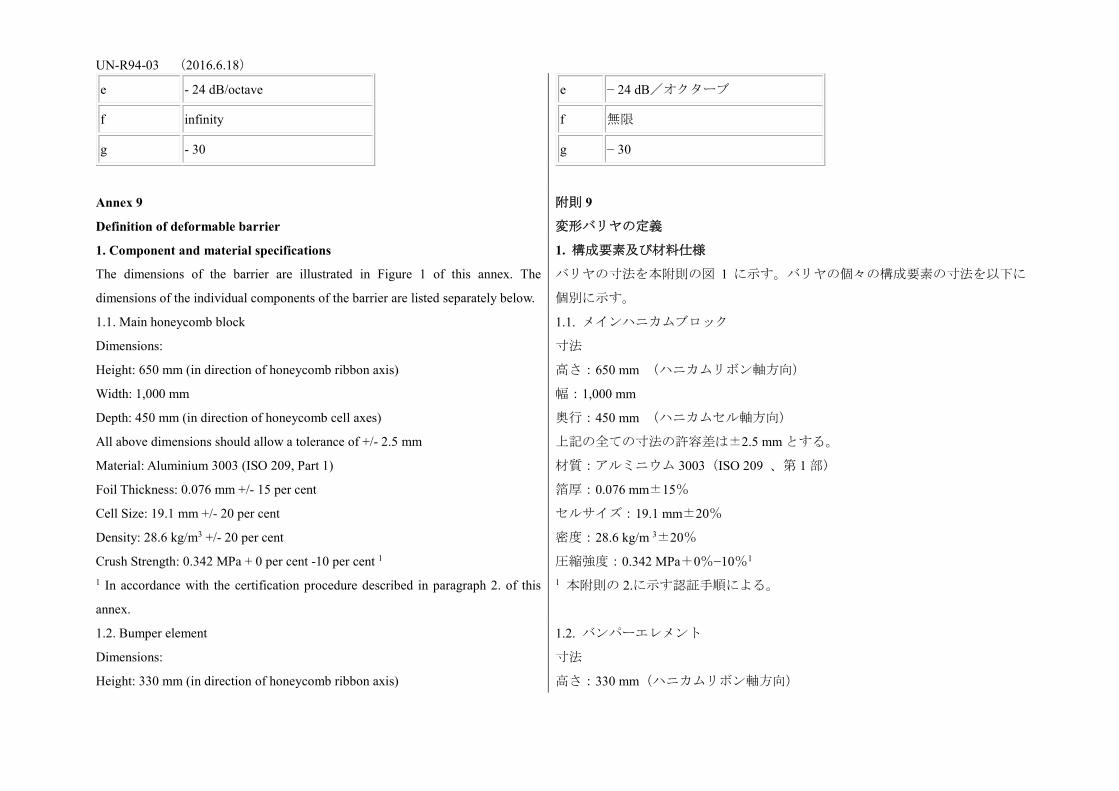
UN-R94-03 (2016.6.18)
e - 24 dB/octave
f infinity
g - 30
e − 24 dB/オクターブ
f 無限
g − 30
Annex 9
Definition of deformable barrier
附則 9
変形バリヤの定義
1. Component and material specifications
The dimensions of the barrier are illustrated in Figure 1 of this annex. The
dimensions of the individual components of the barrier are listed separately below.
1. 構成要素及び材料仕様
バリヤの寸法を本附則の図 1 に示す。バリヤの個々の構成要素の寸法を以下に
個別に示す。
1.1. Main honeycomb block
Dimensions:
Height: 650 mm (in direction of honeycomb ribbon axis)
Width: 1,000 mm
Depth: 450 mm (in direction of honeycomb cell axes)
All above dimensions should allow a tolerance of +/- 2.5 mm
Material: Aluminium 3003 (ISO 209, Part 1)
Foil Thickness: 0.076 mm +/- 15 per cent
Cell Size: 19.1 mm +/- 20 per cent
Density: 28.6 kg/m3 +/- 20 per cent
Crush Strength: 0.342 MPa + 0 per cent -10 per cent 1 1 In accordance with the certification procedure described in paragraph 2. of this
annex.
1.1. メインハニカムブロック
寸法
高さ:650 mm (ハニカムリボン軸方向)
幅:1,000 mm
奥行:450 mm (ハニカムセル軸方向)
上記の全ての寸法の許容差は±2.5 mm とする。
材質:アルミニウム 3003(ISO 209 、第 1 部)
箔厚:0.076 mm±15%
セルサイズ:19.1 mm±20%
密度:28.6 kg/m 3±20%
圧縮強度:0.342 MPa+0%−10%1 1 本附則の 2.に示す認証手順による。
1.2. Bumper element
Dimensions:
Height: 330 mm (in direction of honeycomb ribbon axis)
1.2. バンパーエレメント
寸法
高さ:330 mm(ハニカムリボン軸方向)
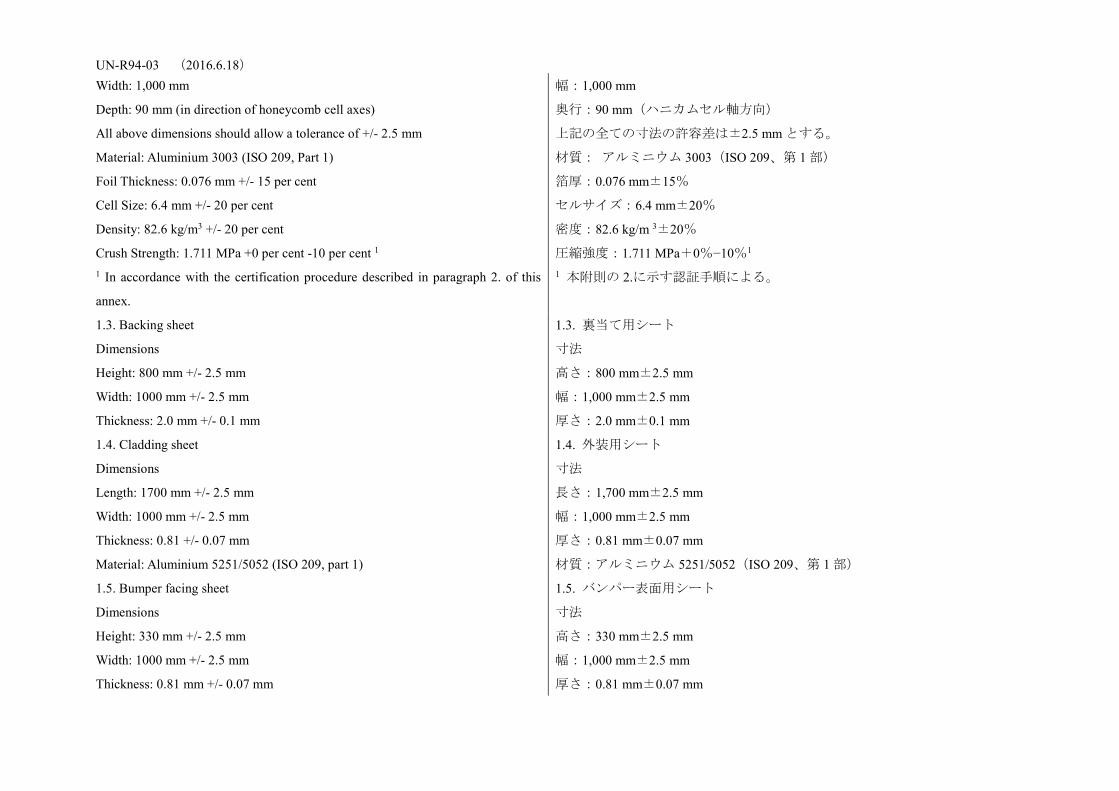
UN-R94-03 (2016.6.18) Width: 1,000 mm
Depth: 90 mm (in direction of honeycomb cell axes)
All above dimensions should allow a tolerance of +/- 2.5 mm
Material: Aluminium 3003 (ISO 209, Part 1)
Foil Thickness: 0.076 mm +/- 15 per cent
Cell Size: 6.4 mm +/- 20 per cent
Density: 82.6 kg/m3 +/- 20 per cent
Crush Strength: 1.711 MPa +0 per cent -10 per cent 1 1 In accordance with the certification procedure described in paragraph 2. of this
annex.
幅:1,000 mm
奥行:90 mm(ハニカムセル軸方向)
上記の全ての寸法の許容差は±2.5 mm とする。
材質: アルミニウム 3003(ISO 209、第 1 部)
箔厚:0.076 mm±15%
セルサイズ:6.4 mm±20%
密度:82.6 kg/m 3±20%
圧縮強度:1.711 MPa+0%−10%1 1 本附則の 2.に示す認証手順による。
1.3. Backing sheet
Dimensions
Height: 800 mm +/- 2.5 mm
Width: 1000 mm +/- 2.5 mm
Thickness: 2.0 mm +/- 0.1 mm
1.3. 裏当て用シート
寸法
高さ:800 mm±2.5 mm
幅:1,000 mm±2.5 mm
厚さ:2.0 mm±0.1 mm
1.4. Cladding sheet
Dimensions
Length: 1700 mm +/- 2.5 mm
Width: 1000 mm +/- 2.5 mm
Thickness: 0.81 +/- 0.07 mm
Material: Aluminium 5251/5052 (ISO 209, part 1)
1.4. 外装用シート
寸法
長さ:1,700 mm±2.5 mm
幅:1,000 mm±2.5 mm
厚さ:0.81 mm±0.07 mm
材質:アルミニウム 5251/5052(ISO 209、第 1 部)
1.5. Bumper facing sheet
Dimensions
Height: 330 mm +/- 2.5 mm
Width: 1000 mm +/- 2.5 mm
Thickness: 0.81 mm +/- 0.07 mm
1.5. バンパー表面用シート
寸法
高さ:330 mm±2.5 mm
幅:1,000 mm±2.5 mm
厚さ:0.81 mm±0.07 mm
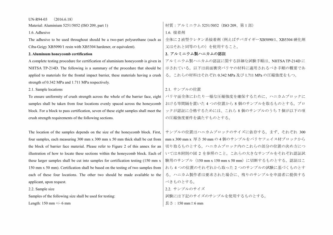
UN-R94-03 (2016.6.18) Material: Aluminium 5251/5052 (ISO 209, part 1) 材質:アルミニウム 5251/5052(ISO 209、第 1 部)
1.6. Adhesive
The adhesive to be used throughout should be a two-part polyurethane (such as
Ciba-Geigy XB5090/1 resin with XB5304 hardener, or equivalent).
1.6. 接着剤
全体に 2 液型ウレタン系接着剤(例えばチバガイギーXB5090/1、XB5304 硬化剤
又はそれと同等のもの)を使用すること。
2. Aluminum honeycomb certification
A complete testing procedure for certification of aluminium honeycomb is given in
NHTSA TP-214D. The following is a summary of the procedure that should be
applied to materials for the frontal impact barrier, these materials having a crush
strength of 0.342 MPa and 1.711 MPa respectively.
2. アルミニウム製ハニカムの認証
アルミニウム製ハニカムの認証に関する詳細な試験手順は、NHTSA TP-214D に
示されている。以下は前面衝突バリヤの材料に適用されるべき手順の概要であ
る。これらの材料はそれぞれ 0.342 MPa 及び 1.711 MPa の圧縮強度をもつ。
2.1. Sample locations
To ensure uniformity of crush strength across the whole of the barrier face, eight
samples shall be taken from four locations evenly spaced across the honeycomb
block. For a block to pass certification, seven of these eight samples shall meet the
crush strength requirements of the following sections.
The location of the samples depends on the size of the honeycomb block. First,
four samples, each measuring 300 mm x 300 mm x 50 mm thick shall be cut from
the block of barrier face material. Please refer to Figure 2 of this annex for an
illustration of how to locate these sections within the honeycomb block. Each of
these larger samples shall be cut into samples for certification testing (150 mm x
150 mm x 50 mm). Certification shall be based on the testing of two samples from
each of these four locations. The other two should be made available to the
applicant, upon request.
2.1. サンプルの位置
バリヤ面全体にわたり一様な圧縮強度を確保するために、ハニカムブロックに
おける等間隔を置いた 4 つの位置から 8 個のサンプルを取るものとする。ブロ
ックが認証に合格するためには、これら 8 個のサンプルのうち 7 個が以下の項
の圧縮強度要件を満たすものとする。
サンプルの位置はハニカムブロックのサイズに依存する。まず、それぞれ 300
mm x 300 mm x 厚さ 50 mm の 4 個のサンプルをバリヤフェイス材ブロックから
切り取るものとする。ハニカムブロック内のこれらの部分の位置の決め方につ
いては本附則の図 2 を参照のこと。これらの大きなサンプルをそれぞれ認証試
験用のサンプル(150 mm x 150 mm x 50 mm)に切断するものとする。認証はこ
れら 4 つの位置のそれぞれから取った 2 つのサンプルの試験に基づくものとす
る。ハニカム製作者は要求された場合に、残りのサンプルを申請者に提供する
べきものとする。
2.2. Sample size
Samples of the following size shall be used for testing:
Length: 150 mm +/- 6 mm
2.2. サンプルのサイズ
試験には下記のサイズのサンプルを使用するものとする。
長さ:150 mm±6 mm
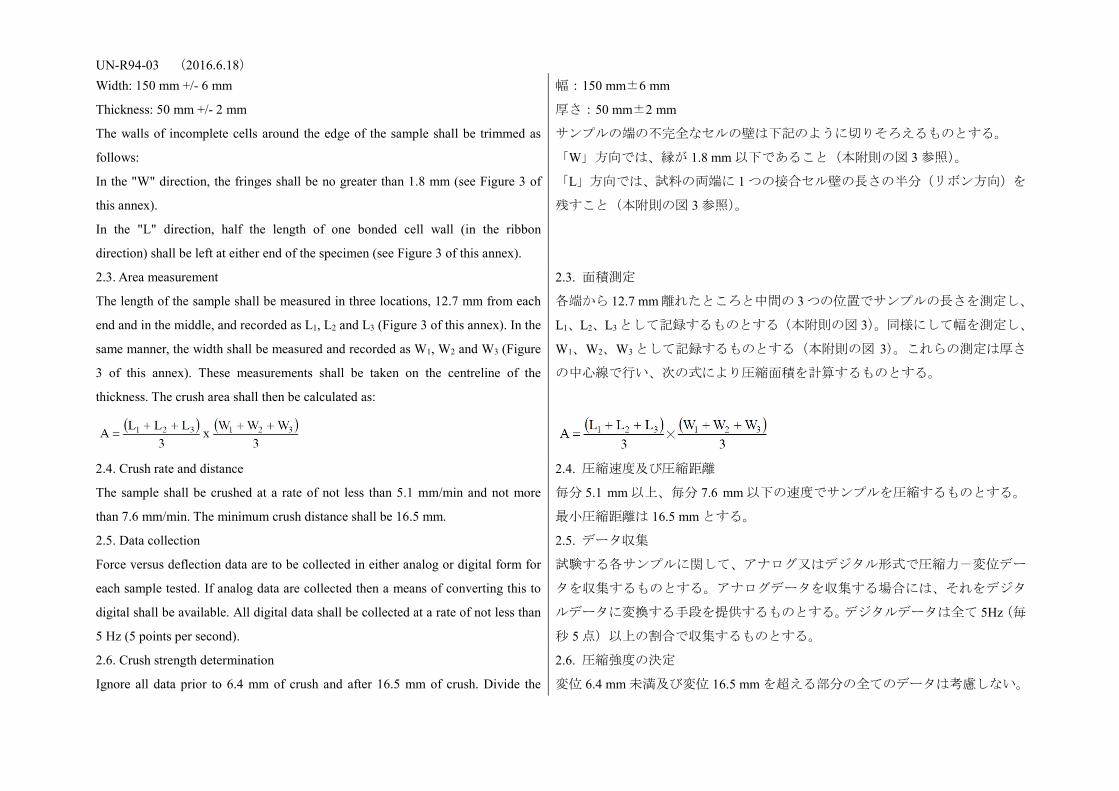
UN-R94-03 (2016.6.18) Width: 150 mm +/- 6 mm
Thickness: 50 mm +/- 2 mm
The walls of incomplete cells around the edge of the sample shall be trimmed as
follows:
In the "W" direction, the fringes shall be no greater than 1.8 mm (see Figure 3 of
this annex).
In the "L" direction, half the length of one bonded cell wall (in the ribbon
direction) shall be left at either end of the specimen (see Figure 3 of this annex).
幅:150 mm±6 mm
厚さ:50 mm±2 mm
サンプルの端の不完全なセルの壁は下記のように切りそろえるものとする。
「W」方向では、縁が 1.8 mm 以下であること(本附則の図 3 参照)。
「L」方向では、試料の両端に 1 つの接合セル壁の長さの半分(リボン方向)を
残すこと(本附則の図 3 参照)。
2.3. Area measurement
The length of the sample shall be measured in three locations, 12.7 mm from each
end and in the middle, and recorded as L1, L2 and L3 (Figure 3 of this annex). In the
same manner, the width shall be measured and recorded as W1, W2 and W3 (Figure
3 of this annex). These measurements shall be taken on the centreline of the
thickness. The crush area shall then be calculated as:
2.3. 面積測定
各端から 12.7 mm 離れたところと中間の 3 つの位置でサンプルの長さを測定し、
L1、L2、L3 として記録するものとする(本附則の図 3)。同様にして幅を測定し、
W1、W2、W3 として記録するものとする(本附則の図 3)。これらの測定は厚さ
の中心線で行い、次の式により圧縮面積を計算するものとする。
2.4. Crush rate and distance
The sample shall be crushed at a rate of not less than 5.1 mm/min and not more
than 7.6 mm/min. The minimum crush distance shall be 16.5 mm.
2.4. 圧縮速度及び圧縮距離
毎分 5.1 mm 以上、毎分 7.6 mm 以下の速度でサンプルを圧縮するものとする。
最小圧縮距離は 16.5 mm とする。
2.5. Data collection
Force versus deflection data are to be collected in either analog or digital form for
each sample tested. If analog data are collected then a means of converting this to
digital shall be available. All digital data shall be collected at a rate of not less than
5 Hz (5 points per second).
2.5. データ収集
試験する各サンプルに関して、アナログ又はデジタル形式で圧縮力-変位デー
タを収集するものとする。アナログデータを収集する場合には、それをデジタ
ルデータに変換する手段を提供するものとする。デジタルデータは全て 5Hz(毎
秒 5 点)以上の割合で収集するものとする。
2.6. Crush strength determination
Ignore all data prior to 6.4 mm of crush and after 16.5 mm of crush. Divide the
2.6. 圧縮強度の決定
変位 6.4 mm 未満及び変位 16.5 mm を超える部分の全てのデータは考慮しない。

UN-R94-03 (2016.6.18) remaining data into three sections or displacement intervals (n = 1, 2, 3) (see
Figure 4 of this annex) as follows:
(1) 06.4 mm - 09.7 mm inclusive,
(2) 09.7 mm - 13.2 mm exclusive,
(3) 13.2 mm - 16.5 mm inclusive.
Find the average for each section as follows:
Where m represents the number of data points measured in each of the three
intervals. Calculate the crush strength of each section as follows:
下記のように残りのデータを 3 つのセクション又は変位間隔(n = 1、2、3)(本
附則の図 4 参照)ごとに分ける。
(1) 06.4 mm 以上− 09.7 mm 以下
(2) 09.7 mm 超え−13.2 mm 未満
(3) 13.2 mm 以上 −16.5 mm 以下
下記のように各セクションの平均を求める。
上の式において、m は 3 つの間隔それぞれにおいて測定したデータ点数を示す。
下記の通り各セクションの圧縮強度を計算する。
2.7. Sample crush strength specification
For a honeycomb sample to pass this certification, the following conditions shall be
met:
0.308 MPa < S(n) < 0.342 MPa for 0.342 MPa material
1.540 MPa < S(n) < 1.711 MPa for 1.711 MPa material
n = 1, 2, 3.
2.7. サンプル圧縮強度仕様
ハニカムサンプルが本認証に合格するためには、下記の条件が満たされるもの
とする。
0.342 MPa 材料については、0.308 MPa<S(n)<0.342 MPa
1.711 MPa 材料については、1.540 MPa<S(n)<1.711 MPa
N = 1、2、3
2.8. Block crush strength specification
Eight samples are to be tested from four locations, evenly spaced across the block.
For a block to pass certification, seven of the eight samples shall meet the crush
strength specification of the previous section.
2.8. ブロック圧縮強度仕様
ブロックにおける等間隔を置いた 4 つの位置から取った 8 個のサンプルを用い
て、試験を実施するものとする。ブロックが認証に合格するためには、8 個のサ
ンプルのうちの 7 個が前項の圧縮強度仕様を満たすものとする。
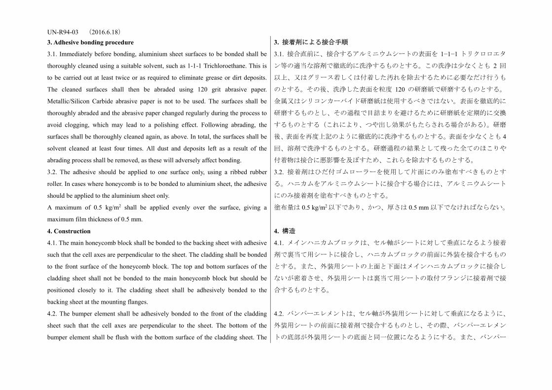
UN-R94-03 (2016.6.18) 3. Adhesive bonding procedure 3. 接着剤による接合手順
3.1. Immediately before bonding, aluminium sheet surfaces to be bonded shall be
thoroughly cleaned using a suitable solvent, such as 1-1-1 Trichloroethane. This is
to be carried out at least twice or as required to eliminate grease or dirt deposits.
The cleaned surfaces shall then be abraded using 120 grit abrasive paper.
Metallic/Silicon Carbide abrasive paper is not to be used. The surfaces shall be
thoroughly abraded and the abrasive paper changed regularly during the process to
avoid clogging, which may lead to a polishing effect. Following abrading, the
surfaces shall be thoroughly cleaned again, as above. In total, the surfaces shall be
solvent cleaned at least four times. All dust and deposits left as a result of the
abrading process shall be removed, as these will adversely affect bonding.
3.1. 接合直前に、接合するアルミニウムシートの表面を 1−1−1 トリクロロエタ
ン等の適当な溶剤で徹底的に洗浄するものとする。この洗浄は少なくとも 2 回
以上、又はグリース若しくは付着した汚れを除去するために必要なだけ行うも
のとする。その後、洗浄した表面を粒度 120 の研磨紙で研磨するものとする。
金属又はシリコンカーバイド研磨紙は使用するべきではない。表面を徹底的に
研磨するものとし、その過程で目詰まりを避けるために研磨紙を定期的に交換
するものとする(これにより、つや出し効果がもたらされる場合がある)。研磨
後、表面を再度上記のように徹底的に洗浄するものとする。表面を少なくとも 4
回、溶剤で洗浄するものとする。研磨過程の結果として残った全てのほこりや
付着物は接合に悪影響を及ぼすため、これらを除去するものとする。
3.2. The adhesive should be applied to one surface only, using a ribbed rubber
roller. In cases where honeycomb is to be bonded to aluminium sheet, the adhesive
should be applied to the aluminium sheet only.
A maximum of 0.5 kg/m2 shall be applied evenly over the surface, giving a
maximum film thickness of 0.5 mm.
3.2. 接着剤はひだ付ゴムローラーを使用して片面にのみ塗布すべきものとす
る。ハニカムをアルミニウムシートに接合する場合には、アルミニウムシート
にのみ接着剤を塗布すべきものとする。
塗布量は 0.5 kg/m2 以下であり、かつ、厚さは 0.5 mm 以下でなければならない。
4. Construction 4. 構造
4.1. The main honeycomb block shall be bonded to the backing sheet with adhesive
such that the cell axes are perpendicular to the sheet. The cladding shall be bonded
to the front surface of the honeycomb block. The top and bottom surfaces of the
cladding sheet shall not be bonded to the main honeycomb block but should be
positioned closely to it. The cladding sheet shall be adhesively bonded to the
backing sheet at the mounting flanges.
4.1. メインハニカムブロックは、セル軸がシートに対して垂直になるよう接着
剤で裏当て用シートに接合し、ハニカムブロックの前面に外装を接合するもの
とする。また、外装用シートの上面と下面はメインハニカムブロックに接合し
ないが密着させ、外装用シートは裏当て用シートの取付フランジに接着剤で接
合するものとする。
4.2. The bumper element shall be adhesively bonded to the front of the cladding
sheet such that the cell axes are perpendicular to the sheet. The bottom of the
bumper element shall be flush with the bottom surface of the cladding sheet. The
4.2. バンパーエレメントは、セル軸が外装用シートに対して垂直になるように、
外装用シートの前面に接着剤で接合するものとし、その際、バンパーエレメン
トの底部が外装用シートの底面と同一位置になるようにする。また、バンパー
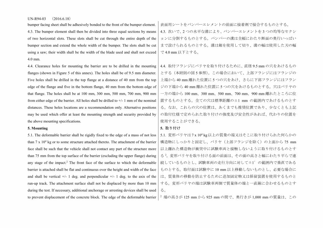
UN-R94-03 (2016.6.18) bumper facing sheet shall be adhesively bonded to the front of the bumper element. 表面用シートをバンパーエレメントの前面に接着剤で接合するものとする。
4.3. The bumper element shall then be divided into three equal sections by means
of two horizontal slots. These slots shall be cut through the entire depth of the
bumper section and extend the whole width of the bumper. The slots shall be cut
using a saw; their width shall be the width of the blade used and shall not exceed
4.0 mm.
4.3. 次いで、2 つの水平な溝により、バンパーエレメントを 3 つの均等なセクシ
ョンに分割するものとする。バンパーの溝は全幅にわたり断面の奥行いっぱい
まで設けられるものとする。溝は鋸を使用して切り、溝の幅は使用した刃の幅
で 4.0 mm 以下とする。
4.4. Clearance holes for mounting the barrier are to be drilled in the mounting
flanges (shown in Figure 5 of this annex). The holes shall be of 9.5 mm diameter.
Five holes shall be drilled in the top flange at a distance of 40 mm from the top
edge of the flange and five in the bottom flange, 40 mm from the bottom edge of
that flange. The holes shall be at 100 mm, 300 mm, 500 mm, 700 mm, 900 mm
from either edge of the barrier. All holes shall be drilled to +/- 1 mm of the nominal
distances. These holes locations are a recommendation only. Alternative positions
may be used which offer at least the mounting strength and security provided by
the above mounting specifications.
4.4. 取付フランジにバリヤを取り付けるために、直径 9.5 mm の穴をあけるもの
とする(本附則の図 5 参照)。この場合において、上部フランジにはフランジの
上端から 40 mm 離れた位置に 5 つの穴をあけ、さらに下部フランジにはフラン
ジの下端から 40 mm 離れた位置に 5 つの穴をあけるものとする。穴はバリヤの
一方の端から 100 mm、300 mm、500 mm、700 mm、900 mm 離れたところに位
置するものとする。全ての穴は標準距離の±1 mm の範囲内であけるものとす
る。なお、これらの穴の位置は、あくまでも推奨位置であり、少なくとも上記
の取付仕様で定められた取り付けの強度及び安全性があれば、代わりの位置を
使用することができる。
5. Mounting 5. 取り付け
5.1. The deformable barrier shall be rigidly fixed to the edge of a mass of not less
than 7 x 10⁴ kg or to some structure attached thereto. The attachment of the barrier
face shall be such that the vehicle shall not contact any part of the structure more
than 75 mm from the top surface of the barrier (excluding the upper flange) during
any stage of the impact.2 The front face of the surface to which the deformable
barrier is attached shall be flat and continuous over the height and width of the face
and shall be vertical +/- 1 deg. and perpendicular +/- 1 deg. to the axis of the
run-up track. The attachment surface shall not be displaced by more than 10 mm
during the test. If necessary, additional anchorage or arresting devices shall be used
to prevent displacement of the concrete block. The edge of the deformable barrier
5.1. 変形バリヤは 7 x 10⁴ kg以上の質量の端又はそこに取り付けられた何らかの
構造物にしっかりと固定し、バリヤ(上部フランジを除く)の上面から 75 mm
以上離れた構造物が衝突中に試験車両と接触しないように取り付けるものとす
る 2。変形バリヤを取り付ける面の前面は、その面の高さと幅にわたり平らで連
続しているものとし、試験車両の走行方向に対して±1゜の範囲内で垂直である
ものとする。取付面は試験中に 10 mm 以上移動しないものとし、必要な場合に
は、質量体の移動を防止するために追加固定物又は係留装置を使用するものと
する。変形バリヤの端は試験車両側で質量体の端と一直線に合わせるものとす
る。 2 端の高さが 125 mm から 925 mm の間で、奥行きが 1,000 mm の質量は、この
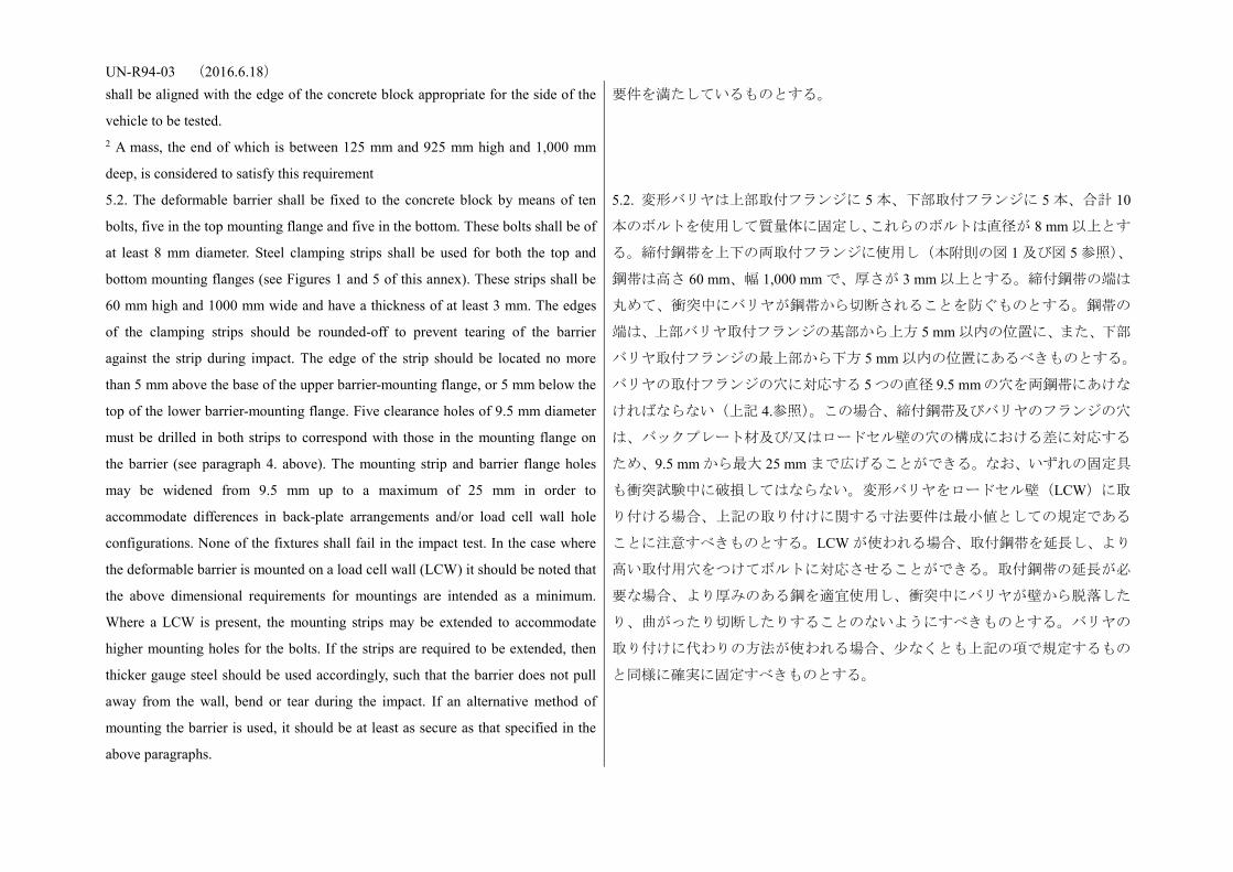
UN-R94-03 (2016.6.18) shall be aligned with the edge of the concrete block appropriate for the side of the
vehicle to be tested. 2 A mass, the end of which is between 125 mm and 925 mm high and 1,000 mm
deep, is considered to satisfy this requirement
要件を満たしているものとする。
5.2. The deformable barrier shall be fixed to the concrete block by means of ten
bolts, five in the top mounting flange and five in the bottom. These bolts shall be of
at least 8 mm diameter. Steel clamping strips shall be used for both the top and
bottom mounting flanges (see Figures 1 and 5 of this annex). These strips shall be
60 mm high and 1000 mm wide and have a thickness of at least 3 mm. The edges
of the clamping strips should be rounded-off to prevent tearing of the barrier
against the strip during impact. The edge of the strip should be located no more
than 5 mm above the base of the upper barrier-mounting flange, or 5 mm below the
top of the lower barrier-mounting flange. Five clearance holes of 9.5 mm diameter
must be drilled in both strips to correspond with those in the mounting flange on
the barrier (see paragraph 4. above). The mounting strip and barrier flange holes
may be widened from 9.5 mm up to a maximum of 25 mm in order to
accommodate differences in back-plate arrangements and/or load cell wall hole
configurations. None of the fixtures shall fail in the impact test. In the case where
the deformable barrier is mounted on a load cell wall (LCW) it should be noted that
the above dimensional requirements for mountings are intended as a minimum.
Where a LCW is present, the mounting strips may be extended to accommodate
higher mounting holes for the bolts. If the strips are required to be extended, then
thicker gauge steel should be used accordingly, such that the barrier does not pull
away from the wall, bend or tear during the impact. If an alternative method of
mounting the barrier is used, it should be at least as secure as that specified in the
above paragraphs.
5.2. 変形バリヤは上部取付フランジに 5 本、下部取付フランジに 5 本、合計 10
本のボルトを使用して質量体に固定し、これらのボルトは直径が 8 mm 以上とす
る。締付鋼帯を上下の両取付フランジに使用し(本附則の図 1 及び図 5 参照)、
鋼帯は高さ 60 mm、幅 1,000 mm で、厚さが 3 mm 以上とする。締付鋼帯の端は
丸めて、衝突中にバリヤが鋼帯から切断されることを防ぐものとする。鋼帯の
端は、上部バリヤ取付フランジの基部から上方 5 mm 以内の位置に、また、下部
バリヤ取付フランジの最上部から下方 5 mm 以内の位置にあるべきものとする。
バリヤの取付フランジの穴に対応する 5 つの直径 9.5 mmの穴を両鋼帯にあけな
ければならない(上記 4.参照)。この場合、締付鋼帯及びバリヤのフランジの穴
は、バックプレート材及び/又はロードセル壁の穴の構成における差に対応する
ため、9.5 mm から最大 25 mm まで広げることができる。なお、いずれの固定具
も衝突試験中に破損してはならない。変形バリヤをロードセル壁(LCW)に取
り付ける場合、上記の取り付けに関する寸法要件は最小値としての規定である
ことに注意すべきものとする。LCW が使われる場合、取付鋼帯を延長し、より
高い取付用穴をつけてボルトに対応させることができる。取付鋼帯の延長が必
要な場合、より厚みのある鋼を適宜使用し、衝突中にバリヤが壁から脱落した
り、曲がったり切断したりすることのないようにすべきものとする。バリヤの
取り付けに代わりの方法が使われる場合、少なくとも上記の項で規定するもの
と同様に確実に固定すべきものとする。

UN-R94-03 (2016.6.18)
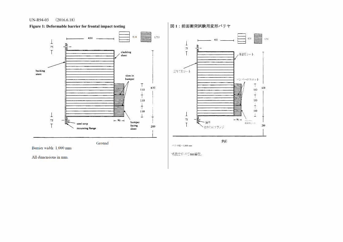
UN-R94-03 (2016.6.18) Figure 1: Deformable barrier for frontal impact testing
図 1:前面衝突試験用変形バリヤ
バリヤ幅=1,000 mm
バンパー 表面用シート
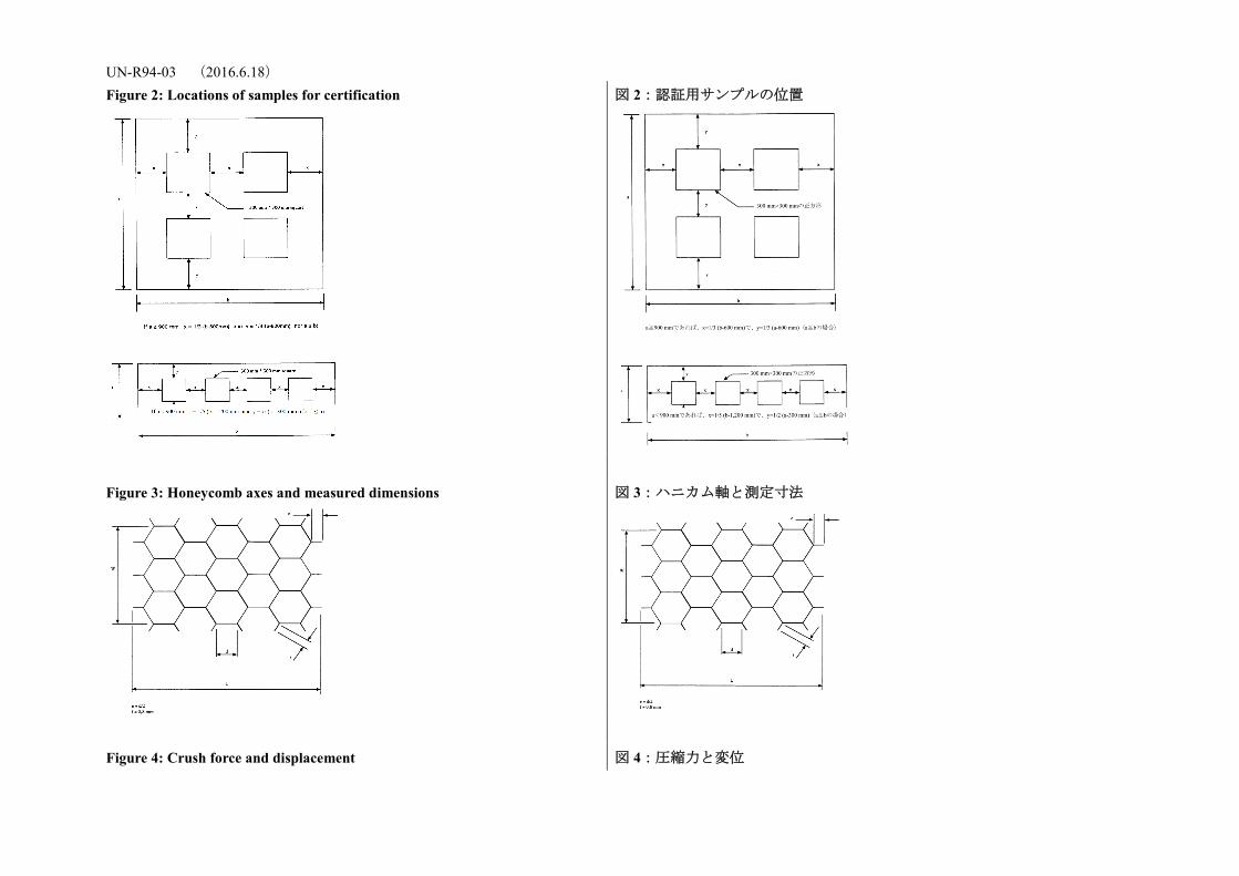
UN-R94-03 (2016.6.18) Figure 2: Locations of samples for certification
図 2:認証用サンプルの位置
Figure 3: Honeycomb axes and measured dimensions
図 3:ハニカム軸と測定寸法
Figure 4: Crush force and displacement 図 4:圧縮力と変位
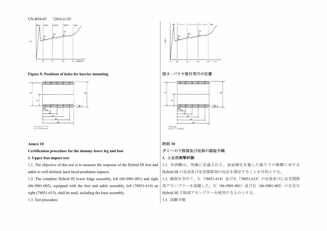
UN-R94-03 (2016.6.18)
Figure 5: Positions of holes for barrier mounting
図 5:バリヤ取付用穴の位置
Annex 10
Certification procedure for the dummy lower leg and foot
附則 10
ダミーの下肢部及び足部の認証手順
1. Upper foot impact test 1. 上足部衝撃試験
1.1. The objective of this test is to measure the response of the Hybrid III foot and
ankle to well-defined, hard faced pendulum impacts.
1.1. 本試験は、明確に定義された、表面硬化を施した振り子の衝撃に対する
Hybrid III の足部及び足首関節部の反応を測定することを目的とする。
1.2. The complete Hybrid III lower ledge assembly, left (86-5001-001) and right
(86-5001-002), equipped with the foot and ankle assembly, left (78051-614) an
right (78051-615), shall be used, including the knee assembly.
1.2. 膝部を含めて、左(78051-614)及び右(78051-615)の足部並びに足首関節
部アセンブリーを装備した、左(86-5001-001)及び右(86-5001-002)の完全な
Hybrid III 下肢部アセンブリーを使用するものとする。
1.3. Test procedure 1.3. 試験手順
圧縮力

UN-R94-03 (2016.6.18) 1.3.1. Each leg assembly shall be maintained (soaked) for four hours prior to the
test at a temperature of 22 deg. C +/- 3 deg. C and a relative humidity of 40 +/- 30
per cent. The soak period shall not include the time required to reach steady state
conditions.
1.3.1. 各脚部アセンブリーを試験前に温度 22℃±3℃及び相対湿度 40±30%に 4
時間保つ(ソークを施す)ものとする。なお、このソーク時間は、定常状態に
達するのに必要な時間は含まないものとする。
1.3.2. Clean the impact surface of the skin and also the impactor face with
isopropyl alcohol or equivalent prior to the test. Dust with talc.
1.3.2. 試験前に皮膚の衝撃面及び衝撃装置の表面をイソプロピルアルコール又
は同等物で洗浄し、滑石でほこりを払うこと。
1.3.3. Align the impactor accelerometer with its sensitive axis parallel to the
direction of impact at contact with the foot.
1.3.3. 計測軸が足部と接触する衝撃方向に平行となるように衝撃装置の加速度
計を調節する。
1.3.4. Mount the leg assembly to the fixture shown in Figure 1 of this annex. The
test fixture shall be rigidly secured to prevent movement during impact. The centre
line of the femur load cell simulator (78051-319) shall be vertical with a tolerance
of +/- 0.5 deg. Adjust the mount such that the line joining the knee clevis joint and
the ankle attachment bolt is horizontal with a tolerance of +/- 3 deg., with the heel
resting on two sheets of a flat low friction (PTFE sheet) surface. Ensure that the
tibia flesh is located fully towards the knee end of the tibia. Adjust the ankle such
that the plane of the underside of the foot is vertical and perpendicular to the
direction of impact with a tolerance of +/- 3 deg. and such that the mid sagittal
plane of the foot is aligned with the pendulum arm. Adjust the knee joint to 1.5 +/-
0.5 g range before each test. Adjust the ankle joint so that it is free and then tighten
just sufficiently to keep the foot stable on the PTFE sheet.
1.3.4. 本附則の図 1 に示す通り、衝撃試験中に移動しないよう脚部アセンブリー
を試験装置にしっかりと取り付ける。この場合、大腿骨ロードセルシミュレー
ター(78051-319)の中心線は、垂直面に対し、±0.5°の範囲内にあり、かつ、
踵を 2 枚の低摩擦平面のシート(PTFE シート)に載せた際、U リンク膝関節部
と足首関節部取付ボルトを結ぶ直線は、水平方向に対して±3°の範囲内で調整
し、脛骨の肉質が完全に脛骨の膝側の方向に位置するようにする。また、足部
の下部の平面は、垂直面に対して±3°の範囲内で、かつ、衝突方向に対して直
角であり、足部の中心線が振り子アームと一直線に並ぶように、足首関節部を
調節する。膝関節部は、各試験前に 1.5±0.5 g の範囲に調整する。なお、足首関
節部は自由になるように調整してから、足部を PTFE 座席上で安定するのに十分
な程度まで固定する。
1.3.5. The rigid impactor comprises a horizontal cylinder diameter 50 +/- 2 mm
and a pendulum support arm diameter 19 +/- 1 mm (Figure 4 of this annex). The
cylinder has a mass of 1.25 +/- 0.02 kg including instrumentation and any part of
the support arm within the cylinder. The pendulum arm has a mass of 285 +/- 5 g.
The mass of any rotating part of the axle to which the support arm is attached
should not be greater than 100 g. The length between the central horizontal axis of
1.3.5. 剛性衝撃装置は、直径 50±2 mm の水平円筒と直径 19±1 mm の振り子支
持アームから成る(本附則の図 4 参照)。円筒は、計器及び円筒内の全ての支持
アームの部分を含めて質量が 1.25±0.02 kg、振り子アームは質量が 285±5 g で、
支持アームを取り付ける軸の回転部分の質量は、100 g以下とすべきものとする。
衝撃円筒の中央水平軸と振り子全体の回転軸の間の距離は、1,250±1 mm とす
る。衝撃円筒は、その縦軸が水平で、衝撃方向に対して垂直になるよう取り付
UN-R94-03 (2016.6.18) the impactor cylinder and the axis of rotation of the whole pendulum shall be 1,250
+/- 1 mm. The
impact cylinder is mounted with its longitudinal axis horizontal and perpendicular
to the direction of impact. The pendulum shall impact the underside of the foot, at a
distance of 185 +/- 2 mm from the base of the heel resting on the rigid horizontal
platform, so that the longitudinal centre line of the pendulum arm falls within 1
deg. of a vertical line at impact. The impactor shall be guided to exclude significant
lateral, vertical or rotational movement.
け、振り子アームの縦中心線が衝突時に垂直線から 1°の範囲になるよう、剛性
水平台に載せた踵の基部から 185±2 mm 離れた足部の下部に振り子が衝突する
ようにする。なお、衝撃装置は、有意な左右、上下又は回転運動がないよう誘
導するものとする。
1.3.6. Allow a period of at least 30 minutes between successive tests on the same
leg.
1.3.6. 同じ脚部で連続して試験を行う場合は、少なくとも 30 分の間隔を置く。
1.3.7. The data acquisition system, including transducers, shall conform to the
specifications for CFC 600, as described in Annex 8.
1.3.7. トランスデューサーを含むデータ収集システムは、附則 8 で規定する
CFC600 の仕様に適合するものとする。
1.4. Performance specification 1.4. 性能仕様
1.4.1. When each ball of the foot is impacted at 6.7 (+/- 0.1) m/s in accordance
with paragraph 1.3. above, the maximum lower tibia bending momentum about the
y-axis (My) shall be 120 +/- 25 Nm.
1.4.1. 上記 1.3 項に従って各足部の拇指球に 6.7(±0.1)m/s で衝撃を与えた際、
y 軸(My)を中心とする下部脛骨の最大曲げモーメントは 120±25 Nm とする。
2. Lower foot impact test without shoe 2. 靴を履かせない下足部の衝撃試験
2.1. The objective of this test is to measure the response of the Hybrid III foot skin
and insert to well-defined, hard faced pendulum impacts.
2.1. 本試験は、明確に定義された、表面硬化を施した振り子の衝撃に対する
Hybrid III の足部の皮膚とインサートの反応を測定することを目的とする。
2.2. The complete Hybrid III lower leg assembly, left (86-5001-001) and right
(86-5001-002), equipped with the foot and ankle assembly, left (78051-614) and
right (78051-615), shall be used, including the knee assembly.
The load cell simulator (78051-319 Rev A) shall be used to secure the knee
assembly (79051-16 Rev B) to the test fixture.
2.2. 膝部を含めて、左(78051-614)及び右(78051-615)の足部並びに足首関節
部アセンブリーを装備した、左(86-5001-001)及び右(86-5001-002)の完全な
Hybrid III 下肢部アセンブリーを使用するものとする。
ロードセルシミュレーター(78051-319 Rev A)により、膝部アセンブリー
(79051-16 Rev B)を試験装置に固定するものとする。
2.3. Test procedure 2.3. 試験手順
2.3.1. Each leg assembly shall be maintained (soaked) for four hours prior to the 2.3.1. 各脚部アセンブリーを試験前に温度 22±3℃及び相対湿度 40±30%に 4時

UN-R94-03 (2016.6.18) test at a temperature of 22 +/- 3 deg. C and a relative humidity of 40 +/- 30 per
cent. The soak period shall not include the time required to reach steady state
conditions.
間保つ(ソークを施す)ものとする。なお、このソーク時間は、定常状態に達
するのに必要な時間は含まないものとする。
2.3.2. Clean the impact surface of the skin and also the impactor face with
isopropyl alcohol or equivalent prior to the test. Dust with talc. Check that there is
no visible damage to the energy absorbing insert to the heel.
2.3.2. 試験前に皮膚の衝撃面及び衝撃装置の表面をイソプロピルアルコール又
は同等物で洗浄し、滑石でほこりを払うこと。また、踵のエネルギー吸収イン
サートに目に見える損傷がないことを確認する。
2.3.3. Align the impactor accelerometer with its sensitive axis parallel to the
impactor longitudinal centre line.
2.3.3. 計測軸が衝撃装置の縦中央線に平行となるよう衝撃装置の加速度計を調
節する。
2.3.4. Mount the leg assembly to the fixture shown in Figure 2 of this annex. The
test fixture shall be rigidly secured to prevent movement during impact. The centre
line of the femur load cell simulator (78051-319) shall be vertical with a tolerance
of +/- 0.5 deg. Adjust the mount such that the line joining the knee clevis joint and
the ankle attachment bolt is horizontal with a tolerance of +/- 3 deg. with the heel
resting on two sheets of a flat low friction (PTFE sheet) surface. Ensure that the
tibia flesh is located fully towards the knee end of the tibia. Adjust the ankle such
that the plane of the underside of the foot is vertical and perpendicular to the
direction of the impact with a tolerance of +/- 3 deg. and such that the mid sagittal
plane of the foot is aligned with the pendulum arm. Adjust the knee joint to 1.5 +/-
0.5 g range before each test. Adjust the ankle joint so that it is free and then tighten
just sufficiently to keep the foot stable on the PTFE sheet.
2.3.4. 本附則の図 2 に示す通り、衝撃試験中に移動しないよう脚部アセンブリー
を試験装置にしっかりと取り付ける。この場合、大腿骨ロードセルシミュレー
ター(78051−319)の中心線は、垂直面に対し、±0.5°の範囲内にあり、かつ、
踵を 2 枚の低摩擦平面のシート(PTFE シート)に載せた際、U リンク膝関節部
と足首関節部取付ボルトを結ぶ直線は、水平方向に対して±3°の範囲内で調整
し、脛骨の肉質が完全に脛骨の膝側の方向に位置するようにする。また、足部
の下部の平面は、垂直面に対して±3°の範囲内で、かつ、衝突方向に対して直
角であり、足部の中心線が振り子アームと一直線に並ぶように、足首関節部を
調節する。膝関節部は、各試験前に 1.5±0.5 g の範囲に調節する。なお、足首関
節部は自由になるように調節してから、足部を PTFE 座席上で安定するのに十分
な程度まで固定する。
2.3.5. The rigid impactor comprises a horizontal cylinder diameter 50 +/- 2 mm
and a pendulum support arm diameter 19 +/- 1 mm (Figure 4 of this annex). The
cylinder has a mass of 1.25 +/- 0.02 kg including instrumentation and any part of
the support arm within the cylinder. The pendulum arm has a mass of 285 +/- 5 g.
The mass of any rotating part of the axle to which the support arm is attached
should not be greater than 100 g. The length between the central horizontal axis of
2.3.5. 剛性衝撃装置は、直径 50±2 mm の水平円筒と直径 19±1 mm の振り子支
持アームから成る(本附則の図 4 参照)。円筒は、計器及び円筒内の全ての支持
アームの部分を含めて質量が 1.25±0.02 kg、振り子アームは質量が 285±5 g で、
支持アームを取り付ける軸の回転部分の質量は、100 g 以下とすること。衝撃円
筒の中央水平軸と振り子全体の回転軸の間の距離は、1,250±1 mm とする。衝撃
円筒は、その縦軸が水平で、衝撃方向に対して垂直になるよう取り付け、振り
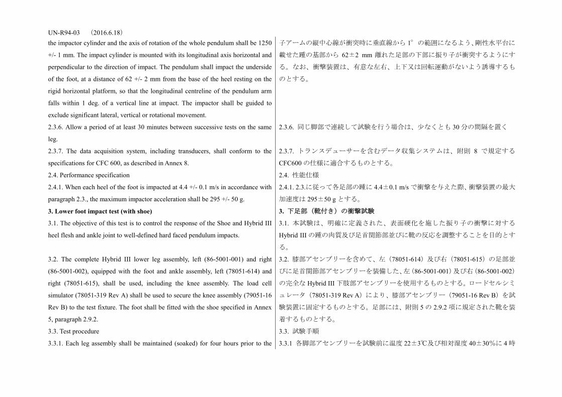
UN-R94-03 (2016.6.18) the impactor cylinder and the axis of rotation of the whole pendulum shall be 1250
+/- 1 mm. The impact cylinder is mounted with its longitudinal axis horizontal and
perpendicular to the direction of impact. The pendulum shall impact the underside
of the foot, at a distance of 62 +/- 2 mm from the base of the heel resting on the
rigid horizontal platform, so that the longitudinal centreline of the pendulum arm
falls within 1 deg. of a vertical line at impact. The impactor shall be guided to
exclude significant lateral, vertical or rotational movement.
子アームの縦中心線が衝突時に垂直線から 1°の範囲になるよう、剛性水平台に
載せた踵の基部から 62±2 mm 離れた足部の下部に振り子が衝突するようにす
る。なお、衝撃装置は、有意な左右、上下又は回転運動がないよう誘導するも
のとする。
2.3.6. Allow a period of at least 30 minutes between successive tests on the same
leg.
2.3.6. 同じ脚部で連続して試験を行う場合は、少なくとも 30 分の間隔を置く
2.3.7. The data acquisition system, including transducers, shall conform to the
specifications for CFC 600, as described in Annex 8.
2.3.7. トランスデューサーを含むデータ収集システムは、附則 8 で規定する
CFC600 の仕様に適合するものとする。
2.4. Performance specification 2.4. 性能仕様
2.4.1. When each heel of the foot is impacted at 4.4 +/- 0.1 m/s in accordance with
paragraph 2.3., the maximum impactor acceleration shall be 295 +/- 50 g.
2.4.1. 2.3.に従って各足部の踵に 4.4±0.1 m/s で衝撃を与えた際、衝撃装置の最大
加速度は 295±50 g とする。
3. Lower foot impact test (with shoe) 3. 下足部(靴付き)の衝撃試験
3.1. The objective of this test is to control the response of the Shoe and Hybrid III
heel flesh and ankle joint to well-defined hard faced pendulum impacts.
3.1. 本試験は、明確に定義された、表面硬化を施した振り子の衝撃に対する
Hybrid III の踵の肉質及び足首関節部並びに靴の反応を調整することを目的とす
る。
3.2. The complete Hybrid III lower leg assembly, left (86-5001-001) and right
(86-5001-002), equipped with the foot and ankle assembly, left (78051-614) and
right (78051-615), shall be used, including the knee assembly. The load cell
simulator (78051-319 Rev A) shall be used to secure the knee assembly (79051-16
Rev B) to the test fixture. The foot shall be fitted with the shoe specified in Annex
5, paragraph 2.9.2.
3.2. 膝部アセンブリーを含めて、左(78051-614)及び右(78051-615)の足部並
びに足首関節部アセンブリーを装備した、左(86-5001-001)及び右(86-5001-002)
の完全な Hybrid III 下肢部アセンブリーを使用するものとする。ロードセルシミ
ュレータ(78051-319 Rev A)により、膝部アセンブリー(79051-16 Rev B)を試
験装置に固定するものとする。足部には、附則 5 の 2.9.2 項に規定された靴を装
着するものとする。
3.3. Test procedure 3.3. 試験手順
3.3.1. Each leg assembly shall be maintained (soaked) for four hours prior to the 3.3.1 各脚部アセンブリーを試験前に温度 22±3℃及び相対湿度 40±30%に 4 時
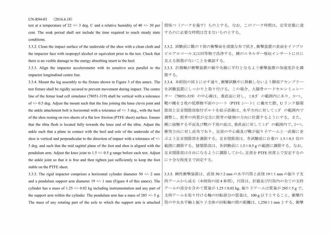
UN-R94-03 (2016.6.18) test at a temperature of 22 +/- 3 deg. C and a relative humidity of 40 +/- 30 per
cent. The soak period shall not include the time required to reach steady state
conditions.
間保つ(ソークを施す)ものとする。なお、このソーク時間は、定常状態に達
するのに必要な時間は含まないものとする。
3.3.2. Clean the impact surface of the underside of the shoe with a clean cloth and
the impactor face with isopropyl alcohol or equivalent prior to the test. Check that
there is no visible damage to the energy absorbing insert to the heel.
3.3.2. 試験前に靴の下部の衝撃面を清潔な布で拭き、衝撃装置の表面をイソプロ
ピルアルコール又は同等物で洗浄する。踵のエネルギー吸収インサートに目に
見える損傷がないことを確認する。
3.3.3. Align the impactor accelerometer with its sensitive axis parallel to the
impactor longitudinal centre line.
3.3.3. 計測軸が衝撃装置の縦中央線に平行となるよう衝撃装置の加速度計を調
節する。
3.3.4. Mount the leg assembly to the fixture shown in Figure 3 of this annex. The
test fixture shall be rigidly secured to prevent movement during impact. The centre
line of the femur load cell simulator (78051-319) shall be vertical with a tolerance
of +/- 0.5 deg. Adjust the mount such that the line joining the knee clevis joint and
the ankle attachment bolt is horizontal with a tolerance of +/- 3 deg., with the heel
of the shoe resting on two sheets of a flat low friction (PTFE sheet) surface. Ensure
that the tibia flesh is located fully towards the knee end of the tibia. Adjust the
ankle such that a plane in contact with the heel and sole of the underside of the
shoe is vertical and perpendicular to the direction of impact with a tolerance of +/-
3 deg. and such that the mid sagittal plane of the foot and shoe is aligned with the
pendulum arm. Adjust the knee joint to 1.5 +/- 0.5 g range before each test. Adjust
the ankle joint so that it is free and then tighten just sufficiently to keep the foot
stable on the PTFE sheet.
3.3.4. 本附則の図 3 に示す通り、衝撃試験中に移動しないよう脚部アセンブリー
を試験装置にしっかりと取り付ける。この場合、大腿骨ロードセルシミュレー
ター(78051-319)の中心線は、垂直面に対し、±0.5°の範囲内にあり、かつ、
靴の踵を 2 枚の低摩擦平面のシート(PTFE シート)に載せた際、U リンク膝関
節部と足首関節部取付ボルトを結ぶ直線は、水平方向に対して±3°の範囲内で
調整し、脛骨の肉質が完全に脛骨の膝側の方向に位置するようにする。また、
踵に接触する平面及び靴の下部の底は、垂直面に対して±3°の範囲内で、かつ、
衝突方向に対し直角であり、足部の中心線及び靴が振り子アームと一直線に並
ぶよう足首関節部を調節する。足首関節部は、各試験前に自重の 1.5±0.5 倍の
範囲に調節する。膝関節部は、各試験前に 1.5±0.5 g の範囲に調節する。なお、
足首関節部は自由になるように調節してから、足部を PTFE 座席上で安定するの
に十分な程度まで固定する。
3.3.5. The rigid impactor comprises a horizontal cylinder diameter 50 +/- 2 mm
and a pendulum support arm diameter 19 +/- 1 mm (Figure 4 of this annex). The
cylinder has a mass of 1.25 +/- 0.02 kg including instrumentation and any part of
the support arm within the cylinder. The pendulum arm has a mass of 285 +/- 5 g.
The mass of any rotating part of the axle to which the support arm is attached
3.3.5. 剛性衝撃装置は、直径 50±2 mm の水平円筒と直径 19±1 mm の振り子支
持アームから成る(本附則の図 4 参照)。円筒は、計器及び円筒内の全ての支持
アームの部分を含めて質量が 1.25±0.02 kg、振り子アームは質量が 285±5 g で、
支持アームを取り付ける軸の回転部分の質量は、100 g 以下とすること。衝撃円
筒の中央水平軸と振り子全体の回転軸の間の距離は、1,250±1 mm とする。衝撃
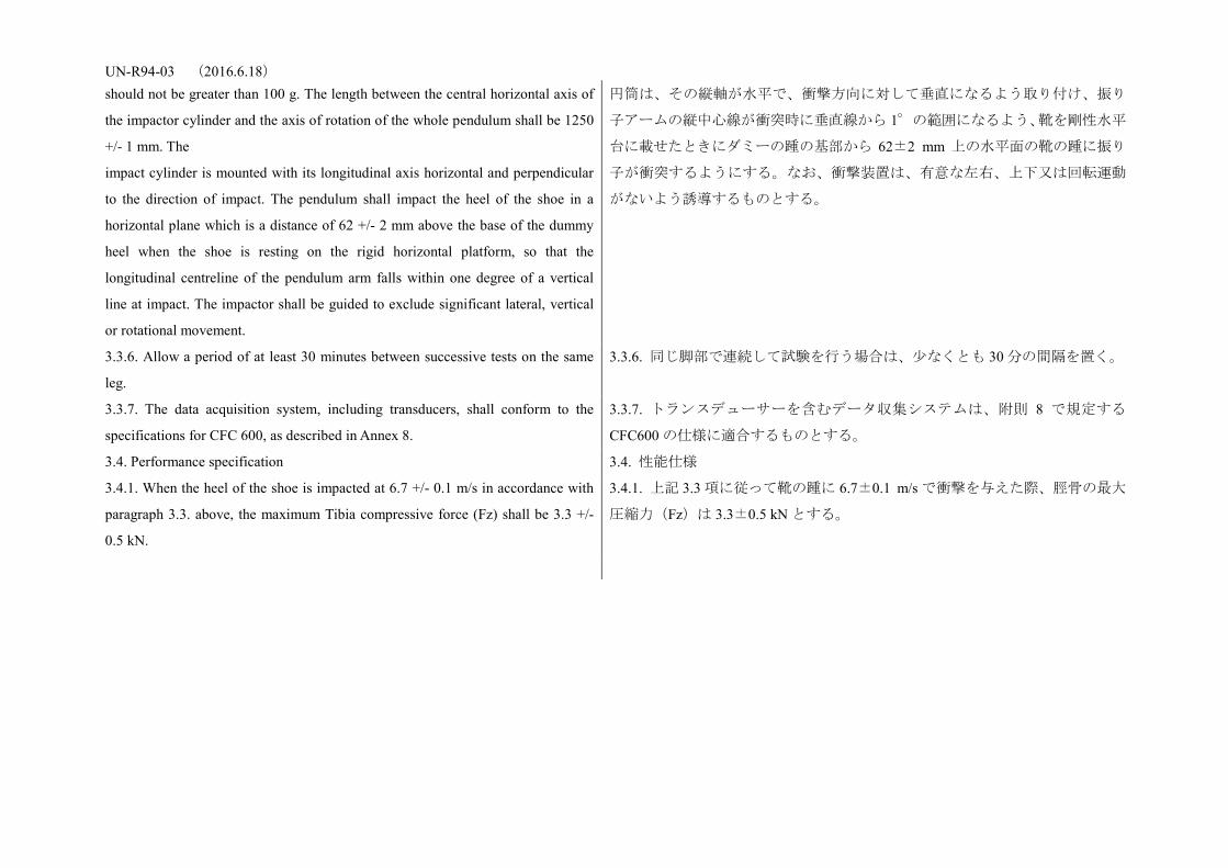
UN-R94-03 (2016.6.18) should not be greater than 100 g. The length between the central horizontal axis of
the impactor cylinder and the axis of rotation of the whole pendulum shall be 1250
+/- 1 mm. The
impact cylinder is mounted with its longitudinal axis horizontal and perpendicular
to the direction of impact. The pendulum shall impact the heel of the shoe in a
horizontal plane which is a distance of 62 +/- 2 mm above the base of the dummy
heel when the shoe is resting on the rigid horizontal platform, so that the
longitudinal centreline of the pendulum arm falls within one degree of a vertical
line at impact. The impactor shall be guided to exclude significant lateral, vertical
or rotational movement.
円筒は、その縦軸が水平で、衝撃方向に対して垂直になるよう取り付け、振り
子アームの縦中心線が衝突時に垂直線から 1°の範囲になるよう、靴を剛性水平
台に載せたときにダミーの踵の基部から 62±2 mm 上の水平面の靴の踵に振り
子が衝突するようにする。なお、衝撃装置は、有意な左右、上下又は回転運動
がないよう誘導するものとする。
3.3.6. Allow a period of at least 30 minutes between successive tests on the same
leg.
3.3.6. 同じ脚部で連続して試験を行う場合は、少なくとも 30 分の間隔を置く。
3.3.7. The data acquisition system, including transducers, shall conform to the
specifications for CFC 600, as described in Annex 8.
3.3.7. トランスデューサーを含むデータ収集システムは、附則 8 で規定する
CFC600 の仕様に適合するものとする。
3.4. Performance specification 3.4. 性能仕様
3.4.1. When the heel of the shoe is impacted at 6.7 +/- 0.1 m/s in accordance with
paragraph 3.3. above, the maximum Tibia compressive force (Fz) shall be 3.3 +/-
0.5 kN.
3.4.1. 上記 3.3 項に従って靴の踵に 6.7±0.1 m/s で衝撃を与えた際、脛骨の最大
圧縮力(Fz)は 3.3±0.5 kN とする。
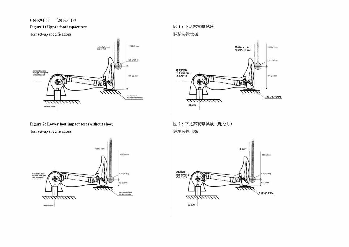
UN-R94-03 (2016.6.18) Figure 1: Upper foot impact test
Test set-up specifications
図 1:上足部衝撃試験
試験装置仕様
Figure 2: Lower foot impact test (without shoe)
Test set-up specifications
図 2:下足部衝撃試験(靴なし)
試験装置仕様
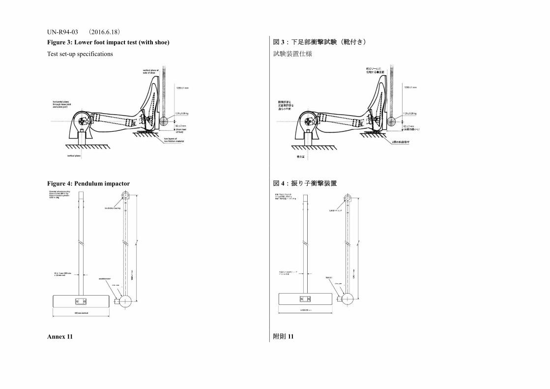
UN-R94-03 (2016.6.18) Figure 3: Lower foot impact test (with shoe)
Test set-up specifications
図 3:下足部衝撃試験(靴付き)
試験装置仕様
Figure 4: Pendulum impactor
図 4:振り子衝撃装置
Annex 11 附則 11
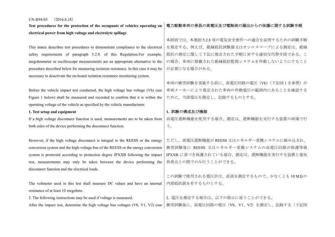
UN-R94-03 (2016.6.18) Test procedures for the protection of the occupants of vehicles operating on
electrical power from high voltage and electrolyte spillage
This annex describes test procedures to demonstrate compliance to the electrical
safety requirements of paragraph 5.2.8. of this Regulation.For example,
megohmmeter or oscilloscope measurements are an appropriate alternative to the
procedure described below for measuring isolation resistance. In this case it may be
necessary to deactivate the on-board isolation resistance monitoring system.
Before the vehicle impact test conducted, the high voltage bus voltage (Vb) (see
Figure 1 below) shall be measured and recorded to confirm that it is within the
operating voltage of the vehicle as specified by the vehicle manufacturer.
電力駆動車両の乗員の高電圧及び電解液の漏出からの保護に関する試験手順
本附則では、本規則 5.2.8 項の電気安全要件への適合を証明するための試験手順
を規定する。例えば、絶縁抵抗試験器又はオシロスコープによる測定は、絶縁
抵抗の測定に関して下記に規定された手順に対する適切な代替手段である。こ
の場合、車両に搭載された絶縁抵抗監視システムを作動しないようにすること
が必要になる場合がある。
車両の衝突試験を実施する前に、高電圧回路の電圧(Vb)(下記図 1 を参照)が
車両メーカーにより規定された車両の作動電圧の範囲内にあることを確認する
ために、当該電圧を測定し、記録するものとする。
1. Test setup and equipment
If a high voltage disconnect function is used, measurements are to be taken from
both sides of the device performing the disconnect function.
However, if the high voltage disconnect is integral to the REESS or the energy
conversion system and the high-voltage bus of the REESS or the energy conversion
system is protected according to protection degree IPXXB following the impact
test, measurements may only be taken between the device performing the
disconnect function and the electrical loads.
The voltmeter used in this test shall measure DC values and have an internal
resistance of at least 10 megohms .
1. 試験の構成及び機器
高電圧遮断機能を使用する場合、測定は、遮断機能を実行する装置の両端で行
う。
ただし、高電圧遮断機能が REESS 又はエネルギー変換システムに組み込まれ、
衝突試験後に REESS 又はエネルギー変換システムの高電圧回路が保護等級
IPXXB に基づき保護されている場合、測定は、遮断機能を実行する装置と電気
負荷点との間でのみ行うことができる。
この試験で使用される電圧計は、直流を測定するもので、少なくとも 10 MΩの
内部抵抗値を有するものとする。
2. The following instructions may be used if voltage is measured.
After the impact test, determine the high voltage bus voltages (Vb, V1, V2) (see
2. 電圧を測定する場合は、以下の指示に従うことができる。
衝突試験後に、高電圧回路の電圧(Vb、V1、V2)を測定し、記録する(下記図
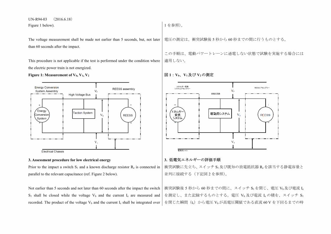
UN-R94-03 (2016.6.18) Figure 1 below).
The voltage measurement shall be made not earlier than 5 seconds, but, not later
than 60 seconds after the impact.
This procedure is not applicable if the test is performed under the condition where
the electric power train is not energized.
1 を参照)。
電圧の測定は、衝突試験後 5 秒から 60 秒までの間に行うものとする。
この手順は、電動パワートレーンに通電しない状態で試験を実施する場合には
適用しない。
Figure 1: Measurement of Vb, V1, V2
図 1:Vb、V1及び V2の測定
3. Assessment procedure for low electrical energy
Prior to the impact a switch S1 and a known discharge resistor Re is connected in
parallel to the relevant capacitance (ref. Figure 2 below).
Not earlier than 5 seconds and not later than 60 seconds after the impact the switch
S1 shall be closed while the voltage Vb and the current Ie are measured and
recorded. The product of the voltage Vb and the current Ie shall be integrated over
3. 低電気エネルギーの評価手順
衝突試験に先立ち、スイッチ S1及び既知の放電抵抗器 Re を該当する静電容量と
並列に接続する(下記図 2 を参照)。
衝突試験後 5 秒から 60 秒までの間に、スイッチ S1を閉じ、電圧 Vb及び電流 Ie
を測定し、また記録するものとする。電圧 Vb 及び電流 Ie の積を、スイッチ S1
を閉じた瞬間(tc)から電圧 Vbが高電圧閾値である直流 60 V を下回るまでの時
エネルギー変換 システムアセンブリー
電気的シャシ
高電圧回路
REESS アセンブリー

UN-R94-03 (2016.6.18) the period of time, starting from the moment when the switch S1 is closed (tc) until
the voltage Vb falls below the high voltage threshold of 60 V DC (th). The resulting
integration equals the total energy (TE) in joules.
(a)
When Vb is measured at a point in time between 5 seconds and 60 seconds after the
impact and the capacitance of the X-capacitors (Cx) is specified by the
manufacturer, total energy (TE) shall be calculated according to the following
formula:
(b) TE = 0.5 x Cx x(Vb2 - 3 600)
When V1 and V2 (see Figure 1 above) are measured at a point in time between 5
seconds and 60 seconds after the impact and the capacitances of the Y-capacitors
(Cy1, Cy2) are specified by the manufacturer, total energy (TEy1, TEy2) shall be
calculated according to the following formulas:
(c) TEy1 = 0.5 x Cy1 x (V12 -3 600)
TEy2 = 0.5 x Cy2 x (V22- 3 600)
This procedure is not applicable if the test is performed under the condition where
the electric power train is not energized.
間(th)で積分するものとする。この積分の結果がジュールを単位とする総エネ
ルギー(TE)となる。
(a)
衝突試験後 5 秒から 60 秒までの間の時点で Vb が測定され、X-キャパシタの静
電容量(Cx)がメーカーから指定されている場合には、総エネルギー(TE)は
以下の式に従って計算するものとする。
(b) TE = 0.5 x Cx x (Vb2 - 3,600)
衝突試験後 5 秒から 60 秒までの間の時点で V1 及び V2(上記図 1 を参照)が測
定され、Y-キャパシタの静電容量(Cy1、Cy2)がメーカーから指定されている
場合には、総エネルギー(TEy1、TEy2)は以下の式に従って計算するものとする。
(c) TEy1 = 0.5 x Cy1 x (V12 -3,600)
TEy2 = 0.5 x Cy2 x (V22- 3,600)
この手順は、電動パワートレーンに通電しない状態で試験を実施する場合には
適用しない。
Figure 2: E.g. measurement of high voltage bus energy stored in X-capacitors 図 2:例:X-キャパシタに貯蔵された高電圧回路エネルギーの測定
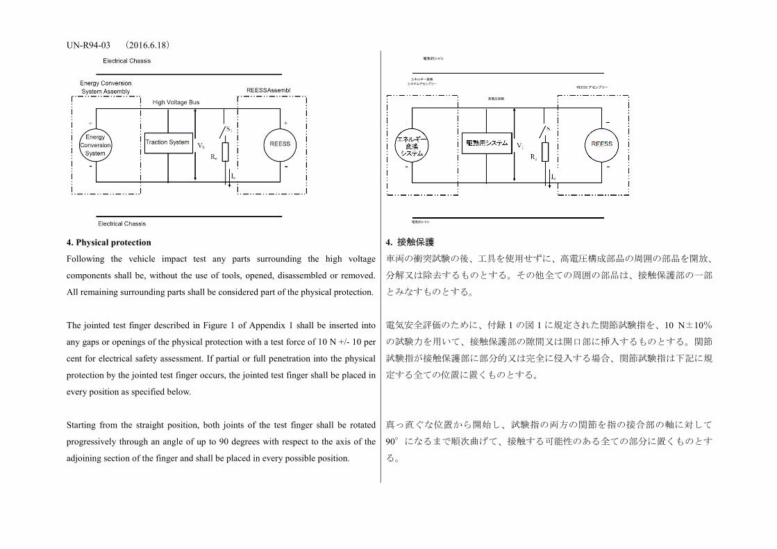
UN-R94-03 (2016.6.18)
4. Physical protection
Following the vehicle impact test any parts surrounding the high voltage
components shall be, without the use of tools, opened, disassembled or removed.
All remaining surrounding parts shall be considered part of the physical protection.
The jointed test finger described in Figure 1 of Appendix 1 shall be inserted into
any gaps or openings of the physical protection with a test force of 10 N +/- 10 per
cent for electrical safety assessment. If partial or full penetration into the physical
protection by the jointed test finger occurs, the jointed test finger shall be placed in
every position as specified below.
Starting from the straight position, both joints of the test finger shall be rotated
progressively through an angle of up to 90 degrees with respect to the axis of the
adjoining section of the finger and shall be placed in every possible position.
4. 接触保護
車両の衝突試験の後、工具を使用せずに、高電圧構成部品の周囲の部品を開放、
分解又は除去するものとする。その他全ての周囲の部品は、接触保護部の一部
とみなすものとする。
電気安全評価のために、付録 1 の図 1 に規定された関節試験指を、10 N±10%
の試験力を用いて、接触保護部の隙間又は開口部に挿入するものとする。関節
試験指が接触保護部に部分的又は完全に侵入する場合、関節試験指は下記に規
定する全ての位置に置くものとする。
真っ直ぐな位置から開始し、試験指の両方の関節を指の接合部の軸に対して
90°になるまで順次曲げて、接触する可能性のある全ての部分に置くものとす
る。
エネルギー変換
システムアセンブリー
電気的シャシ
電気的シャシ
REESS アセンブリー
高電圧回路
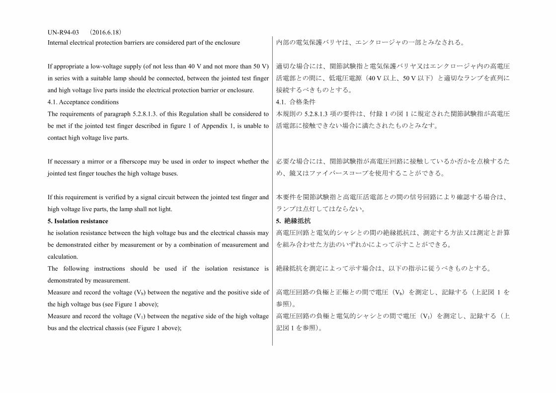
UN-R94-03 (2016.6.18) Internal electrical protection barriers are considered part of the enclosure
If appropriate a low-voltage supply (of not less than 40 V and not more than 50 V)
in series with a suitable lamp should be connected, between the jointed test finger
and high voltage live parts inside the electrical protection barrier or enclosure.
内部の電気保護バリヤは、エンクロージャの一部とみなされる。
適切な場合には、関節試験指と電気保護バリヤ又はエンクロージャ内の高電圧
活電部との間に、低電圧電源(40 V 以上、50 V 以下)と適切なランプを直列に
接続するべきものとする。
4.1. Acceptance conditions
The requirements of paragraph 5.2.8.1.3. of this Regulation shall be considered to
be met if the jointed test finger described in figure 1 of Appendix 1, is unable to
contact high voltage live parts.
If necessary a mirror or a fiberscope may be used in order to inspect whether the
jointed test finger touches the high voltage buses.
If this requirement is verified by a signal circuit between the jointed test finger and
high voltage live parts, the lamp shall not light.
4.1. 合格条件
本規則の 5.2.8.1.3 項の要件は、付録 1 の図 1 に規定された関節試験指が高電圧
活電部に接触できない場合に満たされたものとみなす。
必要な場合には、関節試験指が高電圧回路に接触しているか否かを点検するた
め、鏡又はファイバースコープを使用することができる。
本要件を関節試験指と高電圧活電部との間の信号回路により確認する場合は、
ランプは点灯してはならない。
5. Isolation resistance
he isolation resistance between the high voltage bus and the electrical chassis may
be demonstrated either by measurement or by a combination of measurement and
calculation.
The following instructions should be used if the isolation resistance is
demonstrated by measurement.
Measure and record the voltage (Vb) between the negative and the positive side of
the high voltage bus (see Figure 1 above);
Measure and record the voltage (V1) between the negative side of the high voltage
bus and the electrical chassis (see Figure 1 above);
5. 絶縁抵抗
高電圧回路と電気的シャシとの間の絶縁抵抗は、測定する方法又は測定と計算
を組み合わせた方法のいずれかによって示すことができる。
絶縁抵抗を測定によって示す場合は、以下の指示に従うべきものとする。
高電圧回路の負極と正極との間で電圧(Vb)を測定し、記録する(上記図 1 を
参照)。
高電圧回路の負極と電気的シャシとの間で電圧(V1)を測定し、記録する(上
記図 1 を参照)。
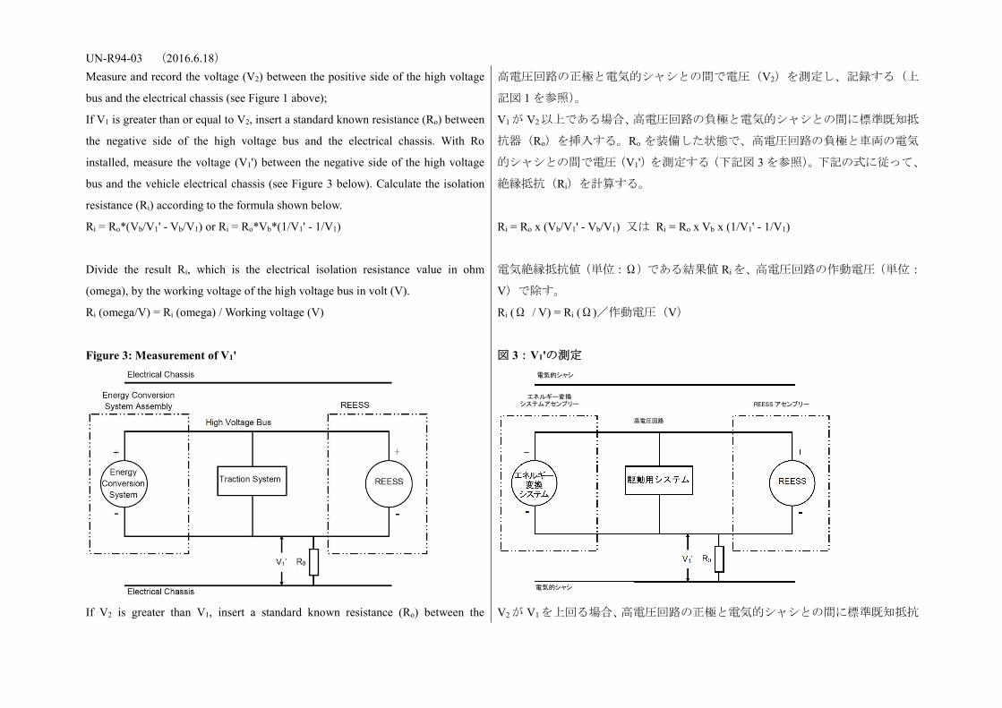
UN-R94-03 (2016.6.18) Measure and record the voltage (V2) between the positive side of the high voltage
bus and the electrical chassis (see Figure 1 above);
If V1 is greater than or equal to V2, insert a standard known resistance (Ro) between
the negative side of the high voltage bus and the electrical chassis. With Ro
installed, measure the voltage (V1') between the negative side of the high voltage
bus and the vehicle electrical chassis (see Figure 3 below). Calculate the isolation
resistance (Ri) according to the formula shown below.
Ri = Ro*(Vb/V1' - Vb/V1) or Ri = Ro*Vb*(1/V1' - 1/V1)
Divide the result Ri, which is the electrical isolation resistance value in ohm
(omega), by the working voltage of the high voltage bus in volt (V).
Ri (omega/V) = Ri (omega) / Working voltage (V)
高電圧回路の正極と電気的シャシとの間で電圧(V2)を測定し、記録する(上
記図 1 を参照)。
V1 が V2以上である場合、高電圧回路の負極と電気的シャシとの間に標準既知抵
抗器(Ro)を挿入する。Ro を装備した状態で、高電圧回路の負極と車両の電気
的シャシとの間で電圧(V1')を測定する(下記図 3 を参照)。下記の式に従って、
絶縁抵抗(Ri)を計算する。
Ri = Ro x (Vb/V1' - Vb/V1) 又は Ri = Ro x Vb x (1/V1' - 1/V1)
電気絶縁抵抗値(単位:Ω)である結果値 Ri を、高電圧回路の作動電圧(単位:
V)で除す。
Ri (Ω / V) = Ri (Ω)/作動電圧(V)
Figure 3: Measurement of V1'
図 3:V1'の測定
If V2 is greater than V1, insert a standard known resistance (Ro) between the V2 が V1を上回る場合、高電圧回路の正極と電気的シャシとの間に標準既知抵抗
電気的シャシ
エネルギー変換 システムアセンブリー REESS アセンブリー
高電圧回路
電気的シャシ
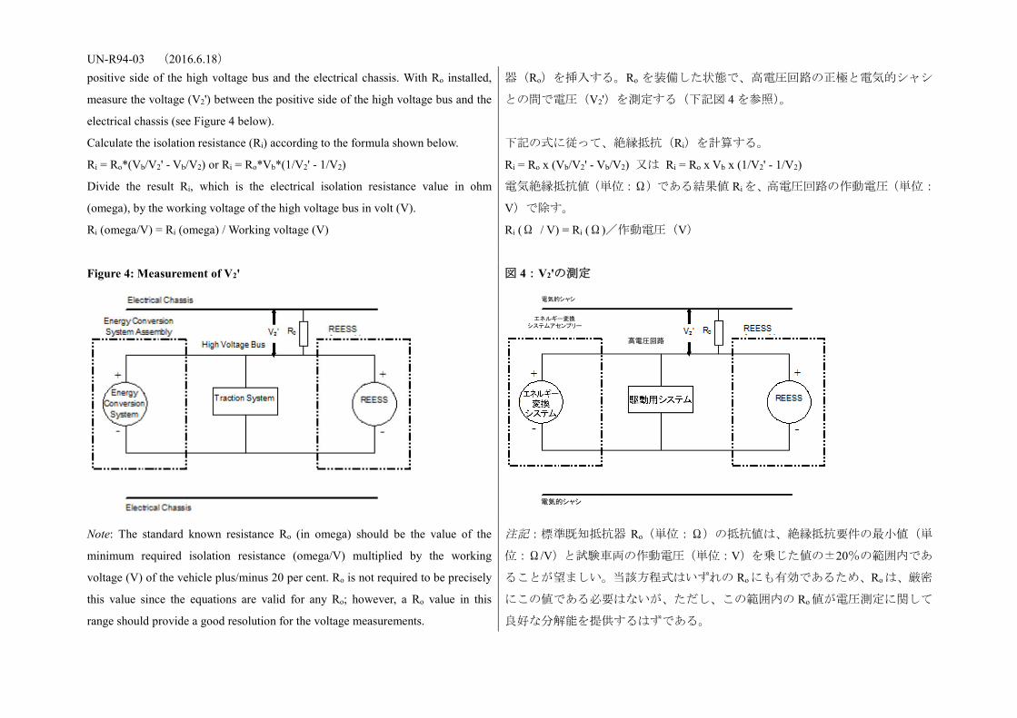
UN-R94-03 (2016.6.18) positive side of the high voltage bus and the electrical chassis. With Ro installed,
measure the voltage (V2') between the positive side of the high voltage bus and the
electrical chassis (see Figure 4 below).
Calculate the isolation resistance (Ri) according to the formula shown below.
Ri = Ro*(Vb/V2' - Vb/V2) or Ri = Ro*Vb*(1/V2' - 1/V2)
Divide the result Ri, which is the electrical isolation resistance value in ohm
(omega), by the working voltage of the high voltage bus in volt (V).
Ri (omega/V) = Ri (omega) / Working voltage (V)
器(Ro)を挿入する。Ro を装備した状態で、高電圧回路の正極と電気的シャシ
との間で電圧(V2')を測定する(下記図 4 を参照)。
下記の式に従って、絶縁抵抗(Ri)を計算する。
Ri = Ro x (Vb/V2' - Vb/V2) 又は Ri = Ro x Vb x (1/V2' - 1/V2)
電気絶縁抵抗値(単位:Ω)である結果値 Ri を、高電圧回路の作動電圧(単位:
V)で除す。
Ri (Ω / V) = Ri (Ω)/作動電圧(V)
Figure 4: Measurement of V2'
図 4:V2'の測定
Note: The standard known resistance Ro (in omega) should be the value of the
minimum required isolation resistance (omega/V) multiplied by the working
voltage (V) of the vehicle plus/minus 20 per cent. Ro is not required to be precisely
this value since the equations are valid for any Ro; however, a Ro value in this
range should provide a good resolution for the voltage measurements.
注記:標準既知抵抗器 Ro(単位:Ω)の抵抗値は、絶縁抵抗要件の最小値(単
位:Ω/V)と試験車両の作動電圧(単位:V)を乗じた値の±20%の範囲内であ
ることが望ましい。当該方程式はいずれの Ro にも有効であるため、Roは、厳密
にこの値である必要はないが、ただし、この範囲内の Ro 値が電圧測定に関して
良好な分解能を提供するはずである。
エネルギー変換 システムアセンブリー
高電圧回路
電気的シャシ
電気的シャシ
UN-R94-03 (2016.6.18) 6. Electrolyte spillage
Appropriate coating shall be applied, if necessary, to the physical protection in
order to confirm any electrolyte leakage from the REESS after the impact test.
Unless the manufacturer provides means to differentiate between the leakage of
different liquids, all liquid leakage shall be considered as the electrolyte.
6. 電解液の漏出
衝突試験後に REESS からの電解液の漏出を確認するため、必要であれば、物理
的保護に対して適切なコーティングを施すものとする。
異なる複数の液体の漏出を区別する手段をメーカーが提供しない場合には、全
ての液体漏出は電解液とみなすものとする。
7. REESS retention
Compliance shall be determined by visual inspection.
7. REESS の位置保持
適合は、目視検査によって判断されるものとする。
Annex 11 - Appendix
Jointed test finger (degree IPXXB)
附則 11−付録
関節試験指(等級 IPXXB)
Figure 1: Jointed test finger 図 1:関節試験指
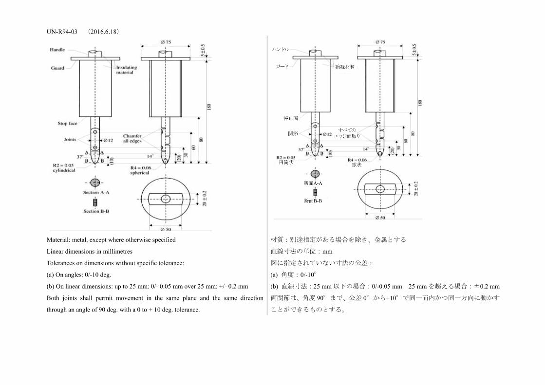
UN-R94-03 (2016.6.18)
Material: metal, except where otherwise specified
Linear dimensions in millimetres
Tolerances on dimensions without specific tolerance:
(a) On angles: 0/-10 deg.
(b) On linear dimensions: up to 25 mm: 0/- 0.05 mm over 25 mm: +/- 0.2 mm
Both joints shall permit movement in the same plane and the same direction
through an angle of 90 deg. with a 0 to + 10 deg. tolerance.
材質:別途指定がある場合を除き、金属とする
直線寸法の単位:mm
図に指定されていない寸法の公差:
(a) 角度:0/-10°
(b) 直線寸法:25 mm 以下の場合:0/-0.05 mm 25 mm を超える場合:±0.2 mm
両関節は、角度 90°まで、公差 0°から+10°で同一面内かつ同一方向に動かす
ことができるものとする。


![INDEX [industrial.panasonic.com]...分類 記載頁 商品名 品 番 ハロゲン フリー 主要用途・ニーズ 銅張積層板 プリプレグ (RCC, 接着シートなど) アンテナ・](https://static.fdocuments.in/doc/165x107/5fa5833da4839f2c0e23bf67/index-e-eee-c-fff-fff-ecefff.jpg)