
UN-GRPE PMP Phase 3 Inter-laboratory Correlation Exercise ...€¦ · 9.3 Weighing Chamber...
31
Working paper No. GRPE-PMP-15-4 (15th PMP working meeting, Geneva 31st May 2005) UN-GRPE PMP Phase 3 Inter-laboratory Correlation Exercise: Updated Framework and Laboratory Guide for HD Engine Testing A Document For The UK Department for Transport Q55022 25 May 2005 RD 04/201901.3b Client Confidential Authors Jon Andersson David Clarke Contributors Approved Diane Lance Manager Chemistry and Aftertreatment
Transcript of UN-GRPE PMP Phase 3 Inter-laboratory Correlation Exercise ...€¦ · 9.3 Weighing Chamber...

Working paper No. GRPE-PMP-15-4 (15th PMP working meeting, Geneva 31st May 2005)
UN-GRPE PMP Phase 3 Inter-laboratory Correlation Exercise: Updated
Framework and Laboratory Guide for HD Engine Testing
A Document For The UK Department for Transport
Q55022 25 May 2005
RD 04/201901.3b Client Confidential
Authors Jon Andersson David Clarke
Contributors
Approved
Diane Lance Manager Chemistry and Aftertreatment

RD04/201901.3b Q55022 Client Confidential DfT
6 June 2005 Page i
Working paper No. GRPE-PMP-15-4 (15th PMP working meeting, Geneva 31st May 2005)
CONTENTS
1. INTRODUCTION ..................................................................................................1 2. SCOPE.................................................................................................................1 3. REFERENCES .....................................................................................................1 4. TEST SPECIFICATIONS......................................................................................2
4.1 Testing Environment...................................................................................2 4.2 Engine Specifications .................................................................................2 4.3 Lubricating Oil ............................................................................................3 4.3.1 Lubricant Flush and Fill...........................................................................3 4.4 Test Fuel ....................................................................................................3
5. TEST PROTOCOL ...............................................................................................3 5.1 Delivery and Preparation of Golden Engine................................................3 5.1.1 Components and Information..................................................................3 5.2 Installation ..................................................................................................4 5.3 Test Cycles.................................................................................................4 5.4 Criteria for Repeat Tests.............................................................................4 5.5 Testing Approach .......................................................................................4 5.6 Test Order and System Preconditioning .....................................................4 5.6.1 Sampling and Measurement System Preconditioning – Evening before 1st Test Day ..........................................................................................................5 5.6.2 Sampling and Measurement System Preconditioning – Each Test Day..5 5.6.3 Preconditioning - Shared Dilution System...............................................5 5.6.4 Continuity Protocol (CP) .........................................................................6
6. MEASUREMENT AND SAMPLING SYSTEMS FOR GASEOUS EMISSIONS....6 6.1 Full flow Dilution System.............................................................................6 6.2 Raw Exhaust Sampling...............................................................................6
7. MEASUREMENT & SAMPLING SYSTEMS FOR PARTICULATES: FULL FLOW 6
7.1 Introduction.................................................................................................6 7.2 Dilution Systems.........................................................................................7 7.2.1 Primary Tunnel .......................................................................................8 7.2.2 Secondary Dilution System.....................................................................8 7.3 Particulate Sampling: Primary Tunnel.........................................................8 7.3.1 Particulate Sampling: Secondary Tunnel ................................................8 7.4 Sample Pre-classifier..................................................................................8 7.5 Filter Sampling ...........................................................................................9 7.5.1 Filter face temperature............................................................................9 7.5.2 Filter holder assembly.............................................................................9 7.5.3 Filter medium..........................................................................................9 7.5.4 Filter size and Stain Area........................................................................9 7.5.5 Filter face velocity/ volumetric sample flow rate ......................................9
8. MEASUREMENT & SAMPLING SYSTEMS FOR PARTICULATES: PARTIAL FLOW............................................................................................................................9
8.1 Introduction.................................................................................................9

RD04/201901.3b Q55022 Client Confidential DfT
6 June 2005 Page ii
Working paper No. GRPE-PMP-15-4 (15th PMP working meeting, Geneva 31st May 2005)
8.2 Dilution System ........................................................................................10 8.3 Dilution System Parameters for Golden Engine........................................10 8.4 Particulate Sampling Point........................................................................11 8.4.1 Particulate Sampling Point for Golden Engine Only ..............................11 8.4.2 Particulate Sampling Point for Additional Engine(s) ..............................11 8.5 Sample Pre-classifier/Probe .....................................................................11 8.6 Filter Sampling .........................................................................................11 8.6.1 Filter face temperature..........................................................................11 8.6.2 Filter holder assembly...........................................................................11 8.6.3 Filter medium........................................................................................11 8.6.4 Filter size and Stain Area......................................................................11 8.6.5 Filter face velocity/ volumetric sample flow rate ....................................12
9. PARTICULATE MEASUREMENT EQUIPMENT AND ENVIRONMENT ............12 9.1 Filter Preparation......................................................................................12 9.2 Microgram balance ...................................................................................12 9.3 Weighing Chamber Parameters................................................................12 9.4 Calibration Requirements .........................................................................13 9.4.1 Microbalance Calibration ......................................................................13 9.4.2 Reference Filter Weighing ....................................................................13
10. GOLDEN PARTICLE MEASUREMENT SYSTEM AND SAMPLING SYSTEMS13 10.1 Particle Sampling System.....................................................................13 10.1.1 Sample Probe: Full flow........................................................................13 10.1.2 Sample Probe: Partial Flow ..................................................................14 10.1.3 Particle Pre-classifier: Full Flow............................................................14 10.1.4 Particle Pre-classifier: Partial Flow........................................................14 10.2 Volatile Particle Remover (VPR)...........................................................14 10.2.1 Description ...........................................................................................14 10.2.2 Elements of the VPR ............................................................................14 10.2.3 Performance.........................................................................................15 10.2.4 Location of Sampling and Measurement Equipment .............................15 10.3 Particle Counter (Particle Number Measurement Unit, PNC) ................15 10.3.1 PNC Performance Characteristics ........................................................15 10.4 Sampling lines ......................................................................................16 10.5 Calibration of Particle Number Measurement System...........................16 10.5.1 Calibration of Particle Number Concentration Measurement Device.....16 10.5.2 Calibration of the diluters ......................................................................17 10.5.3 Calibration of the Volatile Particle Remover ..........................................17 10.6 Additional Sampling And Measurement System For Particles...............17
11. TEST PROCEDURES ........................................................................................17 11.1 Test Matrix............................................................................................17 11.2 Preparation of the Engine .....................................................................18 11.2.1 Instrumentation.....................................................................................18 11.3 Dynamometer Preparation....................................................................18 11.4 Test and Conditioning Protocols ...........................................................18
RD04/201901.3b Q55022 Client Confidential DfT
6 June 2005 Page iii
Working paper No. GRPE-PMP-15-4 (15th PMP working meeting, Geneva 31st May 2005)
11.5 Test Procedures – Gaseous Emissions ................................................19 11.5.1 Preparation for the Test ........................................................................19 11.5.2 During the test ......................................................................................19 11.5.3 Post-test : Full flow dilution ...................................................................19 11.6 Test Procedures – Particulate Emissions: Full and Partial Flow............20 11.6.1 Preparation of the Partial Flow Dilution System ....................................20 11.6.2 Preparation for the Test (filter weighing, switch to bypass) ...................20 11.6.3 During the test (switch to sample).........................................................20 11.6.4 Post-test (condition and weigh filters) ...................................................20 11.7 Test Procedures – Particle Emissions...................................................20 11.7.1 Equipment Arrival at Laboratory............................................................20 11.7.2 List Of Equipment/Components ............................................................20 11.7.3 Initial Checks and Assembly of GPMS [For each system].....................22 11.7.4 Preparation for Daily Protocol: Instrument Warm-up and Daily Verification Exercises .........................................................................................23 11.8 During the test ......................................................................................24 11.9 Post-test ...............................................................................................24 11.9.1 Repeat Daily Verification Exercise ........................................................24 11.10 On Completion Of The Test Matrix .......................................................24
12. DATA CAPTURE AND PRESENTATION IN CORRECT FORMAT ...................25 12.1 Regulated Emissions ............................................................................25 12.2 Particulate Mass ...................................................................................25 12.3 Particle Number....................................................................................25 12.4 Diagnostic Data ....................................................................................26
RD04/201901.3b Q55022 Client Confidential DfT
6 June 2005 Page 1
Working paper No. GRPE-PMP-15-4 (15th PMP working meeting, Geneva 31st May 2005)
PMP PHASE 3 INTER-LABORATORY CORRELATION EXERCISE: HEAVY DUTY ENGINES
1. INTRODUCTION
This document has been prepared in response to a request from UK DfT as part of the Particle Measurement Programme (PMP).
The document’s purpose is to specify the testing guidelines and protocol for an inter-laboratory correlation exercise. This exercise is specifically designed to evaluate the draft revised Regulation 49 document - and its approach to particulate mass and particle number measurements - generated as part of the UK PMP Phase 2 reporting process. The document also introduces particle number and particulate mass measurements from partial flow dilution systems as integral parts of the PMP Phase 3 work.
In Section 9, the document contains specific and detailed guidelines on how the testing should be conducted at each laboratory.
2. SCOPE
This document proposes the scope for Phase III of PMP, the inter-laboratory correlation exercise and addresses the measurement and evaluation methods for particulate (all materials collected by the conventional filter method) and particle (exhaust aerosol; solid particles as defined by the measurement system) exhaust emissions from heavy duty engines under transient conditions on a bench dynamometer. It is derived from the light duty inter-laboratory correlation exercise document (Ricardo RD04/04/80801.4), the existing HD type approval procedure and from draft procedures for future HD legislation (Regulation 49, ISO 16183 and US 2007).
Regulated gaseous emissions will be measured at the same time as particulate and particle emissions, using established regulatory measurement techniques.
This document is concerned with two exhaust dilution systems, namely: a full flow primary dilution tunnel with constant volume sampler (CVS) and secondary dilution system and a partial flow dilution system.
3. REFERENCES
This specification is based upon or draws from the following documents:
Draft UN Working documents:
� R83 - Working Document 6/Rev. 1
� R49 - Working Document 7a (summary)/Rev. 2

RD04/201901.3b Q55022 Client Confidential DfT
6 June 2005 Page 2
Working paper No. GRPE-PMP-15-4 (15th PMP working meeting, Geneva 31st May 2005)
Code of Federal Regulations Title 40 Part 86 Subpart N – Emission Regulations for New Otto-Cycle and Diesel Heavy-Duty Engines; Gaseous and Particulate Exhaust Test Procedures (Revised July 1 2001). “US2007”
ISO16183 Heavy-Duty Engines – Measurement of gaseous emissions from raw exhaust gas and of particulate emissions using partial flow dilution systems under transient test conditions. To be used in its most recent draft and referred to as “16183”.
Euro Directives 1999/96/EC Annex III and 1998/69/EC “Euro”
Aerosol Measurements: Principles, Techniques and Applications.
Ed: Klaus Willeke and Paul A Baron 1993. Van Nostrand Reinhold
Ricardo RD04/231201.1 and 04/80801.4
4. TEST SPECIFICATIONS
4.1 Testing Environment
The participating laboratories shall provide facilities and resources required to perform heavy duty engine emissions tests according to the Regulation 49, plus additional capability as required for particulate and particle measurements as defined in this document. They will also be required to install the test engine, supply measurement systems, and to liaise with the programme managing agent (PMA) and “golden engineer” (GE).
4.2 Engine Specifications
A “golden” engine (nominally Au-E1) will be supplied by the PMA and tested at all participating laboratories. Ideally, this will be one of the following:
� Diesel-fuelled Euro IV compliant engine equipped with catalyst based wallflow DPF � A Euro IV compliant conventional Diesel (without DPF). This is likely to employ high
pressure injection (via CR or EUI) and selective catalytic reduction (SCR) to reach Euro IV NOx and PM levels simultaneously
Laboratories are expected to test an additional engine. This could be:
� Diesel-fuelled Euro IV compliant engine equipped with an OEM system Diesel particulate filter (DPF). Ideally this engine will also be equipped with either common rail (CR) or electronic unit injection (EUI) systems
� A Euro IV compliant conventional Diesel (without DPF). This is likely to employ high pressure injection (via CR or EUI) and EGR to reach Euro IV NOx and PM levels simultaneously
� A Euro IV compliant engine equipped with a Particle oxidation catalyst (POC). � A Euro IV compliant CNG engine
At their own expense, laboratories may test further engines.
RD04/201901.3b Q55022 Client Confidential DfT
6 June 2005 Page 3
Working paper No. GRPE-PMP-15-4 (15th PMP working meeting, Geneva 31st May 2005)
4.3 Lubricating Oil
The same lubrication oil shall be employed for the Golden Engine. The lubricant shall meet the standards specified by the engine manufacturers. Where a range of oils are specified, the minimum sulphur level standard shall be employed.
A large single batch of lubricant will be secured by the project-managing laboratory, analysed and shipped to the test laboratories in advance of the arrival of the test vehicles. The total volume acquired will be sufficient for a rigorous flush and fill procedure for Au-E1 at each laboratory across the entire inter-laboratory correlation exercise. Ideally, this will be the same lubricant as employed during the light duty inter-laboratory correlation exercise.
4.3.1 Lubricant Flush and Fill
A defined flush and fill procedure will be developed, and this employed upon arrival of Au-E1 at each test laboratory. The engine will then be subjected to a standard conditioning procedure to ensure equivalence between laboratories. An example flush and fill procedure is shown in Appendix 1.
4.4 Test Fuel
The Diesel fuel to be employed during this programme will be secured by the project-managing laboratory, analysed and shipped to the test laboratories in advance of the arrival of Au-E1. Ideally, this will be the same Diesel fuel as employed during the light duty inter-laboratory correlation exercise and the fuel will be drawn from a single batch, will comprise sulphur levels of <10ppm and will otherwise comply with Annexes 3 and 4 of Directive 2003/17/EC describing fuel specifications to be employed after 1st January 2009*.
It is estimated that with contingency, each laboratory will require ~3,200 litres of Diesel fuel.
5. TEST PROTOCOL
5.1 Delivery and Preparation of Golden Engine
The test engine shall be inspected for damage on arrival at the laboratory. Any problems shall be reported to the GE and PMA. The engine shall be stored in an appropriate manner prior to installation.
5.1.1 Components and Information
The following components and information shall be provided with the test engine.
� Engine with test bed compatible ECU and control system � Diesel Particulate Filter (DPF) � Other exhaust components: catalysts etc � Diagnostic system � Engine mounts and brackets � Aftercooler and air-side pipe work (pre-set for correct pressure drop across
aftercooler) � Exhaust pipe flange to adapt to test bed system
* If a CNG engine is tested, a fuel specification will be required. Approximately fuel requirements would be 2500-3000kg.

RD04/201901.3b Q55022 Client Confidential DfT
6 June 2005 Page 4
Working paper No. GRPE-PMP-15-4 (15th PMP working meeting, Geneva 31st May 2005)
� Complete dimensions of test cell exhaust system � Wiring harness and throttle pedal � Wiring diagram � Engine operating parameters (eg back pressure, coolant and fuel temp, aftercooler
outlet temperature map etc) � Full load power curve data � Instrumentation for critical engine and aftertreatment operating parameters:
temperatures, pressures etc with suitable quick-fit connectors
5.2 Installation
Care shall be taken to closely replicate the manufactured test cell exhaust system dimensions between laboratories. For example, the distance between exhaust manifold and aftertreatment components shall, as far as possible, be matched between all test laboratories. The critical dimensions of the exhaust system will be supplied with the engine following installation at the first laboratory.
5.3 Test Cycles
The engine shall be tested over at least 16 repeats of the World Heavy Duty Transient Cycle (WHTC). In addition, 8 further tests on each of the European Steady State Cycle (ESC), the World Heavy Duty Steady State Cycle (WHSC) and the European Transient Cycle (ETC) will be undertaken.
5.4 Criteria for Repeat Tests
A minimum of 8 tests of each cycle shall be performed on the engine. Supplementary tests shall be carried out if one or more of the initial tests appears to be an outlier. The criterion for this is if the particulate mass result for one test lies outside ±2 s of the mean of the remaining tests. The outlier will only be rejected if it remains outside the distribution inferred from at least 8 remaining tests. For the ESC, WHSC and ETC a minimum of 8 repeat tests shall be run, if one of these results lies outside ±2 s of the mean of the remaining tests an additional repeat shall be run, if this repeat lies outside ±2 s of the mean of the remaining tests a further repeat shall be run. In the event that both additional repeats lie outside ±2 s of the mean of the remaining tests, no further repeats are required.
5.5 Testing Approach
The test work shall be carried out according to a pre-defined schedule for engine, exhaust & sampling system conditioning, measurement system checks and test cycles. The schedule will depend on the number of test cycles, and will be subject to agreement with the project manager.
5.6 Test Order and System Preconditioning
Test order shall consider the possibility of contamination of test results by a previously tested engine, or from an engine in an adjacent facility which shares the dilution system. Prior to performing any emissions tests, a preconditioning phase shall be completed in order to purge the engine’s exhaust system and to stabilise the dilution system with respect to the chemistry of the engine’s exhaust.
In order to enable close control of both test procedures and test timing, a continuity protocol (Section 5.6.4) is included in the test matrix. The continuity protocol controls

RD04/201901.3b Q55022 Client Confidential DfT
6 June 2005 Page 5
Working paper No. GRPE-PMP-15-4 (15th PMP working meeting, Geneva 31st May 2005)
the time and engine operation between tests specifically, so that testing can be exactly reproduced between laboratories.
5.6.1 Sampling and Measurement System Preconditioning – Evening before 1st Test Day
On the evening before the first test day only, the engine shall be warmed up and operated at ESC Mode 10 for 60 minutes. This period of Mode 10 operation will purge the exhaust system of residual volatile materials and is incorporated within the oil change procedure (Section 4.3.1, Appendix 1).
5.6.2 Sampling and Measurement System Preconditioning – Each Test Day
The exhaust and dilution system shall be conditioned prior to the first measured test each day. This ensures that the entire transfer and dilution system is preconditioned with the test engine. This conditioning shall comprise the following:
� Initial engine operation from cold comprising: ½ Idle [2 minutes] ½ 25% speed and load [10 minutes] ½ 50% speed and load until oil and water temperatures are �����&�>�����PLQXWHV@�
� Power curve [15 minutes] � ESC [30 minutes] � Stabilisation at Mode 4 operation [20 minutes] � If an elective regeneration can be carried out on the engine-DPF system, and this is
approved by the engine manufacturer/DPF supplier, this should be triggered after exactly 5 minutes of the Mode 4 steady state.
� The partial flow sampling system shall be operated in bypass during the conditioning period, with flow settings according to the manufacturers instructions.
An example of a daily test protocol including the preconditioning is given in Figure 1.
Figure 1: Example Test Day - Four Cycles
Time Protocol Testing (mins) Measurements08:00 Warm-up Initial warm-up 30
Power curve 15ESC 28
Stabilisation Mode 4 [elective regen] 20Continuity Idle (4 mins), Mode 4 (10 mins), Idle 16
09:55 WHTC#1 WHTC#1 30 Regulated Emissions, PM, particlesContinuity Idle (4 mins), Mode 4 (10 mins), Idle 16
10:45 WHTC’2 WHTC’2 30 Regulated Emissions, PM, particlesContinuity Idle (4 mins), Mode 4 (10 mins), Idle 16 Instrument Functional verification
11:35 ETC#1 ETC#1 30 Regulated Emissions, PM, particles12:05 Continuity Idle (4 mins), Mode 4 (10 mins), Idle 1612:25 ESC#1 ESC#1 28 Regulated Emissions, PM, particles12:55
Instrument Warm-up and daily verification exercises
Idle engine, Instrument Functional Verification
5.6.3 Preconditioning - Shared Dilution System
In a shared dilution system, where an engine’s exhaust is passed into a dilution tunnel which is shared between 2 or more cells, the preconditioning detailed in Section 5.6.1 must be performed the previous evening and the preconditioning described in Section 5.6.2 undertaken on the test day. The path of the exhaust gases from the engine to the dilution tunnel must be completely isolated from any other test cell(s) or no testing in
RD04/201901.3b Q55022 Client Confidential DfT
6 June 2005 Page 6
Working paper No. GRPE-PMP-15-4 (15th PMP working meeting, Geneva 31st May 2005)
shared cell(s) shall be permitted between the time of the prior evening’s conditioning and the day’s testing.
5.6.4 Continuity Protocol (CP)
Following the Mode 4 stabilisation period and each transient cycle, the continuity protocol shall be applied. The continuity protocol is employed to ensure identical temperature profiles in the engine and exhaust following each test. This will enable the test work to be closely replicated from facility to facility. The protocol is described below: � Drop to idle for 6 minutes � 10 minutes operation at mode 4 � Drop to idle and commence test sequence (Firstly a zero and span of the analysers
and then commencement of the automated part of the emissions cycle)
6. MEASUREMENT AND SAMPLING SYSTEMS FOR GASEOUS EMISSIONS
6.1 Full flow Dilution System
The mass of gaseous emissions shall be measured from the dilute exhaust during all tests in accordance with the current R49 regulation.
6.2 Raw Exhaust Sampling
The mass of gaseous emissions shall be measured from the raw tailpipe exhaust in accordance with R49 regulation for steady-state cycles, and ISO 16183 for transient cycles. If possible, engine out raw emissions shall also be measured on a continuous basis throughout the test.
7. MEASUREMENT & SAMPLING SYSTEMS FOR PARTICULATES: FULL FLOW
7.1 Introduction
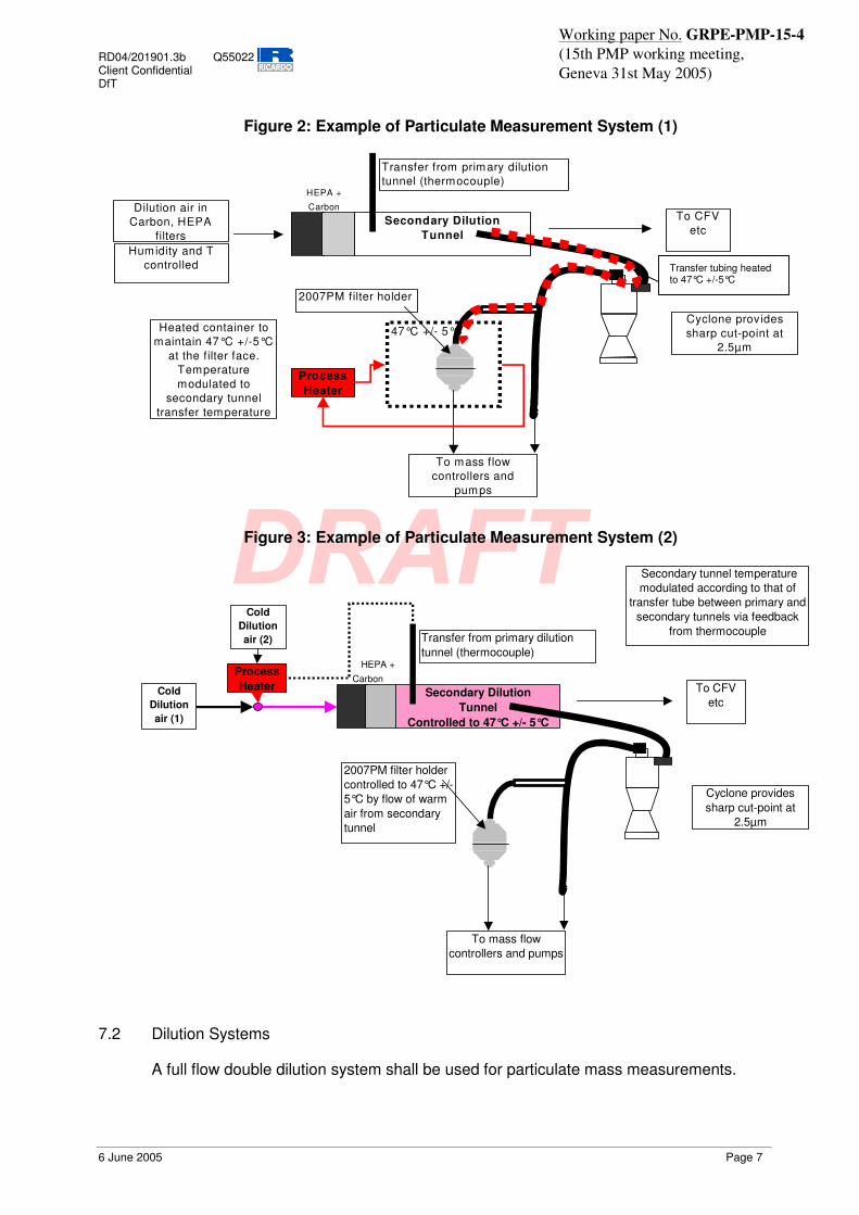
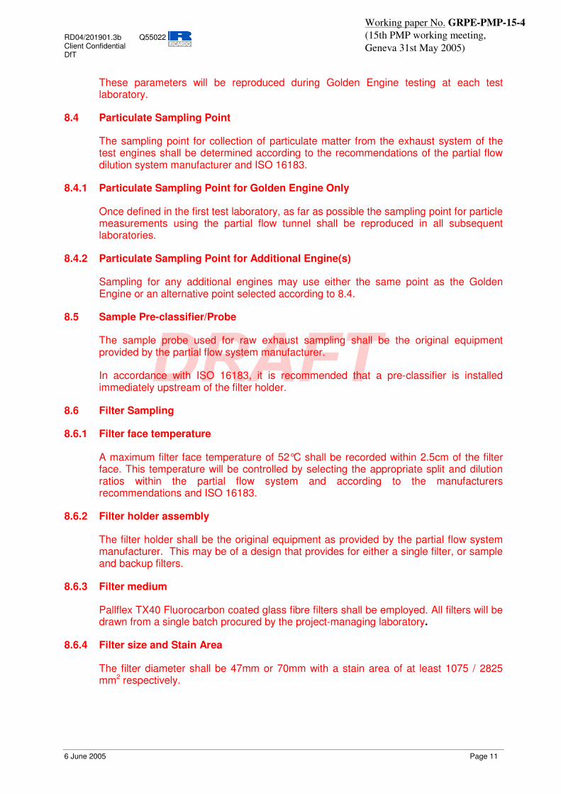
The mass of particulate material emitted by the test engine and for each test will be measured using the system defined in Sections 7.2. to 7.5.5 and Section 9. Two examples of compliant particulate measurement system configurations are shown in Figure 2 and Figure 3.
RD04/201901.3b Q55022 Client Confidential DfT
6 June 2005 Page 7
Working paper No. GRPE-PMP-15-4 (15th PMP working meeting, Geneva 31st May 2005)
Figure 2: Example of Particulate Measurement System (1)
HEPA +
C Carbon
Secondary Dilution Tunnel
To mass flow controllers and
pumps
Cyclone prov ides sharp cut-point at
2.5µm
Dilution air inCarbon, HEPA
filtersHumidity and T
controlled
To CFVetc
Transfer from primary dilution tunnel (thermocouple)
47°C +/- 5°C
ProcessHeater
Heated container to maintain 47°C +/-5°C
at the filter face. Temperature modulated to
secondary tunnel transfer temperature
2007PM filter holder
Figure 3: Example of Particulate Measurement System (2)
HEPA +Carbon
Secondary Dilution Tunnel
Controlled to 47°C +/- 5°C
To mass flow controllers and pumps
Cyclone provides sharp cut-point at
2.5µm
To CFVetc
Transfer from primary dilution tunnel (thermocouple)
Secondary tunnel temperature modulated according to that of
transfer tube between primary and secondary tunnels via feedback
from thermocouple
2007PM filter holdercontrolled to 47°C +/- 5°C by flow of warm air from secondary tunnel
Cold Dilution air (1)
Cold Dilution air (2)
ProcessHeater
7.2 Dilution Systems
A full flow double dilution system shall be used for particulate mass measurements.
Transfer tubing heated to 47°C +/-5°C

RD04/201901.3b Q55022 Client Confidential DfT
6 June 2005 Page 8
Working paper No. GRPE-PMP-15-4 (15th PMP working meeting, Geneva 31st May 2005)
7.2.1 Primary Tunnel
A full flow CVS exhaust dilution tunnel system meeting the requirements of Regulation 49 shall be used. The flow rate of dilute exhaust gas through the tunnel shall be xxm3/min † at standard reference conditions (20°C and 1bar).
The dilution air used for the primary dilution of the exhaust in the CVS tunnel shall be first charcoal scrubbed and then passed through a secondary filter. The secondary filter should be capable of reducing particles in the most penetrating particle size of the filter material by at least 99.95%, or through a filter of at least class H13 of EN 1822; this represents the specification of High Efficiency Particulate Air (HEPA) filters.
7.2.2 Secondary Dilution System
A secondary dilution system meeting the requirements of Regulation 49 shall be used. The dilution ratio in the secondary dilution system shall be fixed at 2 parts dilution air to one part sample aerosol.
The dilution air for the secondary dilution system shall be subject to HEPA and charcoal filtration.
7.3 Particulate Sampling: Primary Tunnel
A sample probe shall conduct materials to the secondary dilution tunnel. It shall be installed near the tunnel centre-line, 10 - 20 tunnel diameters downstream of the gas inlet and have an internal diameter of at least 12 mm. The sample probe will be sharp-edged and open ended, facing directly into the direction of flow in the primary dilution tunnel.
7.3.1 Particulate Sampling: Secondary Tunnel
A sample probe will be installed in the secondary dilution tunnel. It shall be sharp-edged and open ended, facing directly into the direction of flow.
A cyclone or impactor based pre-classifier shall be employed.
A pump will draw a sample of dilute exhaust gas proportional to the total tunnel flow through the sample pre-classifier and filter holder.
The distance from the sampling tip to the filter mount shall be at least five probe diameters, but shall not exceed 1,020 mm.
7.4 Sample Pre-classifier
In accordance with the recommendations of the draft Regulation 49 document, a cyclone or impactor pre-classifier shall be located upstream of the filter holder assembly. The pre-classifier 50% cut point particle diameter shall be between 2.5 µm and 10 µm at the volumetric flow rate selected for sampling particulate mass emissions. The pre-classifier shall allow at least 99% of the mass concentration of 1µm particles entering the pre-classifier to pass through the exit of the pre-classifier at the volumetric flow rate selected for sampling particulate mass emissions. Evidence of compliant performance to this specification shall be presented (e.g. manufacturer’s calibration certificate). † Dependent on engine selected, but could be ~40m3/min

RD04/201901.3b Q55022 Client Confidential DfT
6 June 2005 Page 9
Working paper No. GRPE-PMP-15-4 (15th PMP working meeting, Geneva 31st May 2005)
7.5 Filter Sampling
7.5.1 Filter face temperature
A temperature of 47±5°C shall be maintained within 2.5cm of the filter face.
This shall be achieved by either direct heating means: the filter holder shall be heated by a mantle or similar, or be mounted inside a temperature-controlled enclosure with the transfer lines to the filter holder heated to enable a residence time of at least 0.2s at 47°C +/-5°C to be achieved.
Or
The temperature of the aerosol within the secondary dilution tunnel shall be controlled to 47°C+/-5°C by heating of the dilution air. In this case, the temperature of the dilution air shall be modulated in response to the temperature of the transfer gases between the primary and secondary dilution tunnels. Residence time at ~47°C in the secondary tunnel and at the filter face shall be at least 0.2s.
7.5.2 Filter holder assembly
The filter holder assembly shall be of a design that provides for a single filter only. The shape of the holder shall be such that an even flow distribution of sample across the filter stain area is achieved.
7.5.3 Filter medium
Pallflex TX40 Fluorocarbon coated glass fibre filters shall be employed. All filters will be drawn from a single batch procured by the project-managing laboratory.
7.5.4 Filter size and Stain Area
The filter diameter shall be 47mm and the stain area shall be at least 1075 mm2.
7.5.5 Filter face velocity/ volumetric sample flow rate
Filter face velocity shall be in the range 50cm/s to 80cm/s, which corresponds to a flow rate range of 35l/min to 51l/min. Filter face velocity should be calculated at 47°C or temperature corrected mass-flow controllers used.
8. MEASUREMENT & SAMPLING SYSTEMS FOR PARTICULATES: PARTIAL FLOW
8.1 Introduction
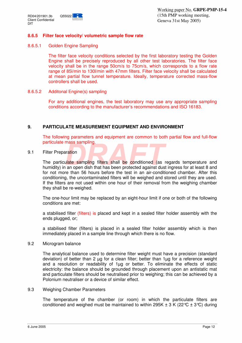
The mass of particulate material emitted by the test engine and for each test will be measured using the system defined in Sections 8.2. to 8.6.4 and Section 9. An example of a compliant particulate measurement system configuration is shown in Figure 4.
Sampling and measurements will be undertaken according to ISO 16183 except where parameters are explicitly specified in this document.

RD04/201901.3b Q55022 Client Confidential DfT
6 June 2005 Page 10
Working paper No. GRPE-PMP-15-4 (15th PMP working meeting, Geneva 31st May 2005)
Figure 4: Example of Partial Flow Measurement System
DAF
EP
SP
TT
DT
d
FM1
FC2
GEXH
or GAIR
GFUEL or
exhaust
PTT
FM3
FC3
FH
BV
P
8.2 Dilution System
A partial flow, single dilution system meeting the requirements of ISO 16183 shall be used for particulate mass measurements in tandem with the full flow system. Exhaust gas mass flow shall be determined using one of the methods outlined in ISO 16183, and the resulting data shall be used for controlling the sample rate from the raw exhaust into the partial flow dilution tunnel.
For transient tests, attention should be given to the dynamic performance of the various measurement and control systems, and good engineering practise should be employed as required to ensure that the sample drawn from the raw exhaust is proportional to the exhaust flow rate at the sample point. The use of a pre-recorded exhaust flow trace for look-ahead control is allowed.
The same flow measurement and control approach as used for transient cycles shall be used for steady state tests.
The dilution system shall be capable of achieving the filter sampling conditions as outlined in Section 8.6 below.
8.3 Dilution System Parameters for Golden Engine
For the Golden Engine only, dilution system operating parameters such as split ratio, dilution factor and filter flow rate will be determined which provide reactive control, maximum tunnel temperature of 52°C, filter loading of >150µg and filter face velocity in the permitted range (Section 8.6.5.1) for all test cycles.
RD04/201901.3b Q55022 Client Confidential DfT
6 June 2005 Page 11
Working paper No. GRPE-PMP-15-4 (15th PMP working meeting, Geneva 31st May 2005)
These parameters will be reproduced during Golden Engine testing at each test laboratory.
8.4 Particulate Sampling Point
The sampling point for collection of particulate matter from the exhaust system of the test engines shall be determined according to the recommendations of the partial flow dilution system manufacturer and ISO 16183.
8.4.1 Particulate Sampling Point for Golden Engine Only
Once defined in the first test laboratory, as far as possible the sampling point for particle measurements using the partial flow tunnel shall be reproduced in all subsequent laboratories.
8.4.2 Particulate Sampling Point for Additional Engine(s)
Sampling for any additional engines may use either the same point as the Golden Engine or an alternative point selected according to 8.4.
8.5 Sample Pre-classifier/Probe
The sample probe used for raw exhaust sampling shall be the original equipment provided by the partial flow system manufacturer.
In accordance with ISO 16183, it is recommended that a pre-classifier is installed immediately upstream of the filter holder.
8.6 Filter Sampling
8.6.1 Filter face temperature
A maximum filter face temperature of 52°C shall be recorded within 2.5cm of the filter face. This temperature will be controlled by selecting the appropriate split and dilution ratios within the partial flow system and according to the manufacturers recommendations and ISO 16183.
8.6.2 Filter holder assembly
The filter holder shall be the original equipment as provided by the partial flow system manufacturer. This may be of a design that provides for either a single filter, or sample and backup filters.
8.6.3 Filter medium
Pallflex TX40 Fluorocarbon coated glass fibre filters shall be employed. All filters will be drawn from a single batch procured by the project-managing laboratory.
8.6.4 Filter size and Stain Area
The filter diameter shall be 47mm or 70mm with a stain area of at least 1075 / 2825 mm2 respectively.
RD04/201901.3b Q55022 Client Confidential DfT
6 June 2005 Page 12
Working paper No. GRPE-PMP-15-4 (15th PMP working meeting, Geneva 31st May 2005)
8.6.5 Filter face velocity/ volumetric sample flow rate
8.6.5.1 Golden Engine Sampling
The filter face velocity conditions selected by the first laboratory testing the Golden Engine shall be precisely reproduced by all other test laboratories. The filter face velocity shall be in the range 50cm/s to 75cm/s, which corresponds to a flow rate range of 85l/min to 130l/min with 47mm filters. Filter face velocity shall be calculated at mean partial flow tunnel temperature. Ideally, temperature corrected mass-flow controllers shall be used.
8.6.5.2 Additonal Engine(s) sampling
For any additional engines, the test laboratory may use any appropriate sampling conditions according to the manufacturer’s recommendations and ISO 16183.
9. PARTICULATE MEASUREMENT EQUIPMENT AND ENVIRONMENT
The following parameters and equipment are common to both partial flow and full-flow particulate mass sampling.
9.1 Filter Preparation
The particulate sampling filters shall be conditioned (as regards temperature and humidity) in an open dish that has been protected against dust ingress for at least 8 and for not more than 56 hours before the test in an air-conditioned chamber. After this conditioning, the uncontaminated filters will be weighed and stored until they are used. If the filters are not used within one hour of their removal from the weighing chamber they shall be re-weighed.
The one-hour limit may be replaced by an eight-hour limit if one or both of the following conditions are met:
a stabilised filter (filters) is placed and kept in a sealed filter holder assembly with the ends plugged, or;
a stabilised filter (filters) is placed in a sealed filter holder assembly which is then immediately placed in a sample line through which there is no flow.
9.2 Microgram balance
The analytical balance used to determine filter weight must have a precision (standard deviation) of better than 2 µg for a clean filter; better than 1µg for a reference weight and a resolution or readability of 1µg or better. To eliminate the effects of static electricity: the balance should be grounded through placement upon an antistatic mat and particulate filters should be neutralised prior to weighing; this can be achieved by a Polonium neutraliser or a device of similar effect.
9.3 Weighing Chamber Parameters
The temperature of the chamber (or room) in which the particulate filters are conditioned and weighed must be maintained to within 295K ± 3 K (22°C ± 3°C) during
RD04/201901.3b Q55022 Client Confidential DfT
6 June 2005 Page 13
Working paper No. GRPE-PMP-15-4 (15th PMP working meeting, Geneva 31st May 2005)
all filter conditioning and weighing. The humidity must be maintained to a dew point of 282.5K ± 3 K (9.5°C ± 3°C) and a relative humidity of 45 % ± 8 %.
The weighing room parameters should be controlled as tightly as possible.
9.4 Calibration Requirements
9.4.1 Microbalance Calibration
The microbalance shall be calibrated according to the manufacturer’s specification within 3 months prior to the commencement of the test programme.
9.4.2 Reference Filter Weighing
At least two unused reference filters must be weighed within 4 hours of, but preferably at the same time as the sample filter weighings. They must be the same size and material as the sample filters. If the average weight of the reference filters changes between sample filter weighings by more than ± 5µg, then the sample filter must be discarded and the emissions test repeated.
10. GOLDEN PARTICLE MEASUREMENT SYSTEM AND SAMPLING SYSTEMS
The number of particles emitted by each engine technology and for each test cycle shall be determined using two nominally identical ‘Golden Particle Measurement Systems’ (GPMS) defined below‡. Particle numbers shall be determined by measurement from the primary dilution tunnel (full flow)§ and from the partial flow dilution system. The majority of GPMS components will be provided, though certain items indicated in the text shall be provided by the laboratory.
10.1 Particle Sampling System
The particle sampling system shall be identical for the two GPMS systems with the exception of the sampling tubes. Two sampling tubes will be required: in the primary dilution tunnel for full flow sampling (PSTf) and partial flow dilution tunnel for partial flow sampling (PSTp). Further elements of the particle sampling system are: a particle pre-classifier (PCF) and the GPMS particle conditioning and measurement system comprising a volatile particle remover (VPR) upstream of the particle number counter (PNC_GOLD) unit. The particle sampling system is required to draw a sample from the primary or partial flow dilution systems, size classify it, transfer it to a diluter, condition the sample so that only solid particles are measured, and pass a suitable concentration of those particles to the particle counter.
10.1.1 Sample Probe: Full flow
A particle sampling tube (PSTf) shall be installed near the primary tunnel centre line, 10 to 20 tunnel diameters downstream of the gas inlet, facing upstream into the tunnel gas flow with its axis at the tip parallel to that of the dilution tunnel. The tube shall be sharp
‡ For the purposes of this document it is assumed that the Golden Particle Measurement System to be employed in the ILCE_HD will be the same as employed in the ILCE_LD. This is not necessarily the case. § Particle number sampling from the primary and NOT secondary dilution system. This is not the ideal scenario, but the majority of laboratories do not have true secondary dilution systems and to allow consistency the primary tunnel must be used.

RD04/201901.3b Q55022 Client Confidential DfT
6 June 2005 Page 14
Working paper No. GRPE-PMP-15-4 (15th PMP working meeting, Geneva 31st May 2005)
edged and open-ended and have an internal diameter of approximately 12.5mm. The PSTf may be heated to no greater than 52°C.
The distance from the sampling tip to the point at which the probe leaves the dilution tunnel shall be less than 200 mm and the distance from the sampling tip to the entrance to the particle pre-classifier unit shall not exceed 1,000 mm. The particle sampling tube shall be placed in a position equivalent to that of the probe employed for particulate mass sampling: all sampling probes and tubes shall be equally spaced about the centre line of the dilution tunnel with at least 5cm separation between them.
10.1.2 Sample Probe: Partial Flow
A sample probe will be installed in the partial flow dilution tunnel. It shall be sharp-edged and open ended and comprised of stainless steel. The sampling point for the sample probe shall not be shared with the probe employed for particulate mass measurements.
10.1.3 Particle Pre-classifier: Full Flow
The upper limit of the particle size range to be measured shall be determined by the use of the cyclone particle size pre-classifier provided. The 50% cut-point of the particle pre-classifier shall lie at 2.5µm. The laboratory will provide a suitable pump to ensure an upper size limit of particles sampled into the measurement system of 2.5µm.
10.1.4 Particle Pre-classifier: Partial Flow**
The upper limit of the particle size range to be measured shall be determined by the use of an inertial particle size pre-classifier. The 50% cut-point of the particle pre-classifier shall lie at 2.5µm. The laboratory will provide a suitable pump to ensure an upper size limit of particles sampled into the measurement system of 2.5µm.
10.2 Volatile Particle Remover (VPR)
The VPR shall be used to define the nature of the particles to be measured.
10.2.1 Description
The VPR provides heated dilution, thermal conditioning of the sample aerosol, further dilution for selection of particle number concentration and cooling of the sample prior to entry into the particle number counter.
10.2.2 Elements of the VPR
The VPR shall comprise the following elements:
10.2.2.1 First Particle Number Diluter (PND1)
The PND1 diluter shall be specifically designed to dilute particle number concentration and output a dilute sample equal to 150°C +/- 5°C. The diluter should be supplied with HEPA filtered dilution air and be capable of a dilution ratio range of 1 to 1000 times. For the Golden Engines, the dilution ratios of this diluter; PNDR1 will be determined at the
** The operating capabilities of the partial flow systems may prohibit two large flows being drawn simultaneously from the partial flow tunnel. It will be necessary to use either a different inertial separator to that used with the full flow dilution system or to omit the inertial separator altogether.

RD04/201901.3b Q55022 Client Confidential DfT
6 June 2005 Page 15
Working paper No. GRPE-PMP-15-4 (15th PMP working meeting, Geneva 31st May 2005)
first test laboratory and replicated at subsequent sites. For additional engines, the dilution ratio will be determined by experimentation and agreed with the GE and PMA.
10.2.2.2 Evaporation Tube (ET)
The ET shall be a length of tubing 240mm +/-10 mm and I.D 6mm +/- 0.1mm equipped with a heating mantle. The entire length of the ET must be controlled to a temperature greater than that of PND1, with a portion of the length equivalent to a gas residence time of 0.2s +/- 0.05s held at a constant temperature of 300°C (+/-20°C).
10.2.2.3 Second Particle Number Diluter (PND2)
The PND2 device shall be specifically designed to dilute particle number concentration. The diluter shall be supplied with HEPA filtered dilution air and be capable of a dilution ratio of ~ 10 times. The dilution ratio of this diluter; PNDR2 is selected such that particle number concentration downstream the PND2 diluter is <104 particles/cm3 and the gas temperature prior to entry to the PNC_GOLD is <35°C.
10.2.3 Performance
The VPR shall operate under conditions that achieve greater than 99% reduction of 30nm C40 (tetracontane) particles and greater than 80% solid particle penetration at 30, 50 and 100nm particle diameter.
10.2.4 Location of Sampling and Measurement Equipment
The distance from the sampling tip of PSTf and PSTp to the entrance to the 3°D1 shall not exceed 1000mm.
The distance from the sampling tip to the point at which the probe leaves the dilution tunnel shall be less than 200 mm.
The distance from the sampling tip to the entrance to the particle number counting instrument shall not exceed 2,500 mm.
10.3 Particle Counter (Particle Number Measurement Unit, PNC)
The particle counter is used to determine the number concentration of solid particles in a diluted sample of engine exhaust aerosol continuously drawn from the CVS.
10.3.1 PNC Performance Characteristics
The particle number concentration measurement unit (PNC_GOLD) shall meet the following conditions:
� It shall operate under full flow operating conditions
� It shall have a counting accuracy of ± 10% across the range 102cm-3 to 104cm-3 and +/- 10cm-3
below this concentration against a traceable standard
� It shall have a readability of 0.1 particles/cm3
� It shall have a linear response to particle concentration over 1 to 10,000 particles/cm3

RD04/201901.3b Q55022 Client Confidential DfT
6 June 2005 Page 16
Working paper No. GRPE-PMP-15-4 (15th PMP working meeting, Geneva 31st May 2005)
� It shall have a data logging frequency of equal to 0.5 Hz or better
� It shall have a T90 response time of between 5s and 15s
� It shall have a data-averaging period of between 1 and 6s and shall not incorporate automatic data manipulation functions
The lower particle size limit characteristics of the PNC_GOLD shall be such that the 10% (D10), 25% (D25), 50% (D50) and 90% (D90) inlet efficiencies of the instrument correspond to the particle sizes 16nm (+/-nm), 18nm (+/-2nm), 23nm (+/-3nm and 37nm (+/-4nm) respectively��
10.3.1.1 Reference Particle Counter
A second particle counter (PNC_REF), with identical specification to PNC_GOLD will be transported with PNC_GOLD to act as a reference instrument. This instrument will also be operating during testing to indicate the real time function of the VPR.
10.4 Sampling lines
All sampling lines shall be either TYGON (specifically R3603), conductive silicone tubing or of stainless steel composition, contain smooth internal surfaces and be of minimal length. Sharp bends and abrupt changes in section should be avoided in all sampling lines.
10.5 Calibration of Particle Number Measurement System
Prior to commencement of the test programme, calibration of the PNCs, diluters and VPR will be undertaken. This may be by the by the instrument manufacturers, but shall be according to the protocols described in the following sections:
10.5.1 Calibration of Particle Number Concentration Measurement Device
The particle counter shall be calibrated according to the manufacturer’s specification within one month prior to testing in the first laboratory. Calibration shall be traceable to a standard calibration method:
� comparison of the response of the counter under calibration with that of a calibrated aerosol electrometer when simultaneously sampling electrostatically classified calibration particles, or
� comparison of the response of the counter under calibration with that of a second counter which has been calibrated by the above method.
In either case, calibration shall be undertaken at five concentrations spaced as uniformly as possible across the single particle detection region of the counter’s measurement range. Calibration spacing will be ~10000, ~8000, ~6000, ~4000, ~2000cm-3 (plus zero check). Measured concentrations shall be within ±10% of the standard concentration for each calibration concentration used. The gradient from a linear regression of the two data sets shall be calculated and recorded. Linearity of response is calculated as the square of the Pearson product moment correlation coefficient (R2) of the two data sets and shall be equal to or greater than 0.95.
RD04/201901.3b Q55022 Client Confidential DfT
6 June 2005 Page 17
Working paper No. GRPE-PMP-15-4 (15th PMP working meeting, Geneva 31st May 2005)
10.5.2 Calibration of the diluters
It is considered unlikely that fully characterised diluters (with fully understood size-related losses) will be available within the timeframe of the inter-laboratory correlation exercise and it is recognised that calibration with gases will not necessarily indicate the exact dilution ratios obtained for aerosols. However, the practicality of the inter-laboratory exercise is for consistency between test laboratories, and this can be provided by a well designed diluter with low predicted losses and stable gas dilution ratio performance.
The diluter shall be calibrated with a traceable standard gas mixture within one month prior to testing in the first laboratory. Calibration shall be undertaken by measuring the concentration of the standard gas with a calibrated gas monitor at the inlet and outlet of the diluter.
Calibration shall be undertaken at least 5 dilution ratios spaced as uniformly as possible across the dilution ratio range from 0 to 1000.
Measured dilution ratios shall be within ±10% of nominal dilution ratio settings. If a diluter is to be used over a narrower dilution range, then the 5-point calibration should span that range.
10.5.3 Calibration of the Volatile Particle Remover
The penetration efficiency of solid particles through the apparatus shall be established within one month prior to testing in the first laboratory.
The test aerosol for these measurements shall be solid particles of diameters 30, 50 and 100 nm and a minimum concentration of 1,000 particles/cm3. Particle concentrations shall be measured upstream and downstream of the apparatus operating at the temperature and flow conditions employed during an emission test. A minimum penetration efficiency of 80% shall be achieved at all three test particle diameters.
10.6 Additional Sampling And Measurement System For Particles
The laboratory shall propose its own specific particle number measurement system and operate this in parallel with the GPMS. Data from this system shall be collected simultaneously with that from the GPMS, and the two sets compared and contrasted. The sampling and measurement of particles with the laboratories’ own systems shall not interfere with measurements from the GPMS. Alternative systems installations will be subject to approval by the GE and/or PMA.
11. TEST PROCEDURES
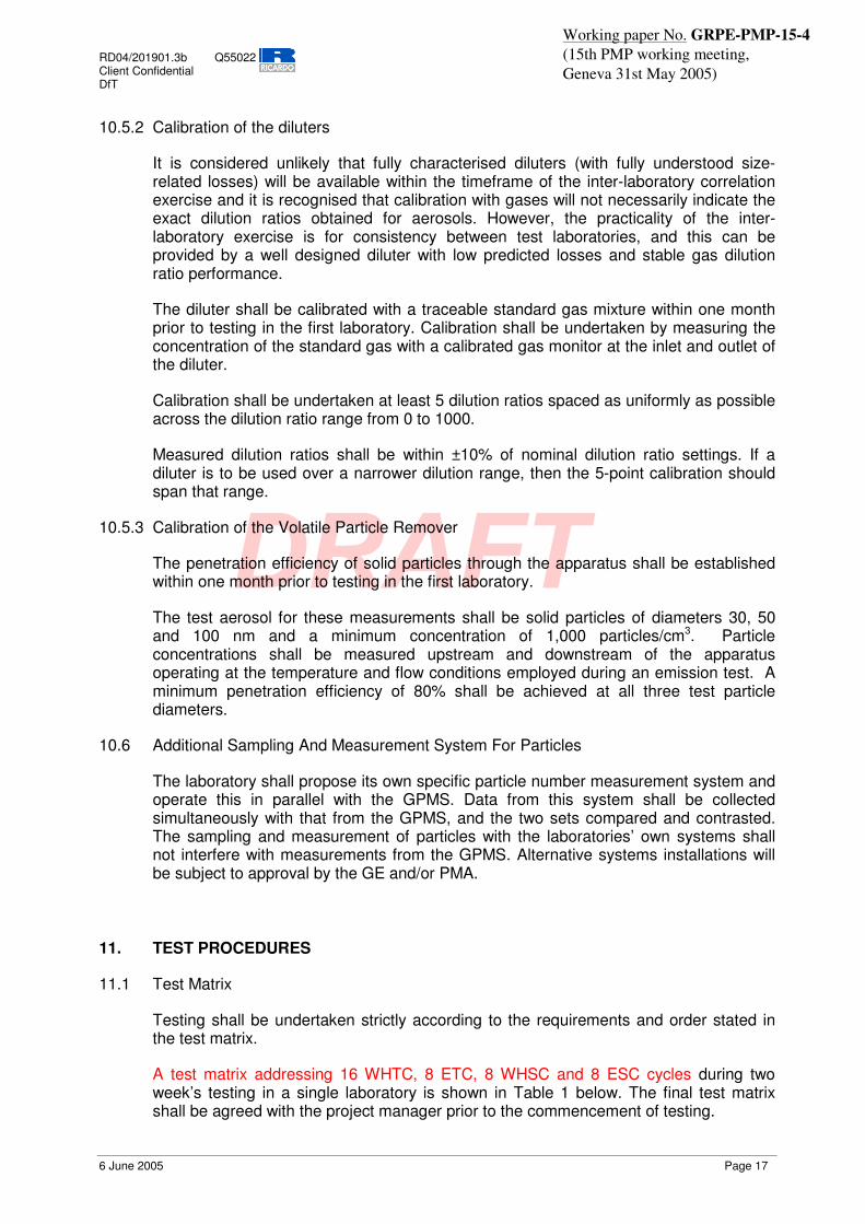
11.1 Test Matrix
Testing shall be undertaken strictly according to the requirements and order stated in the test matrix.
A test matrix addressing 16 WHTC, 8 ETC, 8 WHSC and 8 ESC cycles during two week’s testing in a single laboratory is shown in Table 1 below. The final test matrix shall be agreed with the project manager prior to the commencement of testing.
RD04/201901.3b Q55022 Client Confidential DfT
6 June 2005 Page 18
Working paper No. GRPE-PMP-15-4 (15th PMP working meeting, Geneva 31st May 2005)
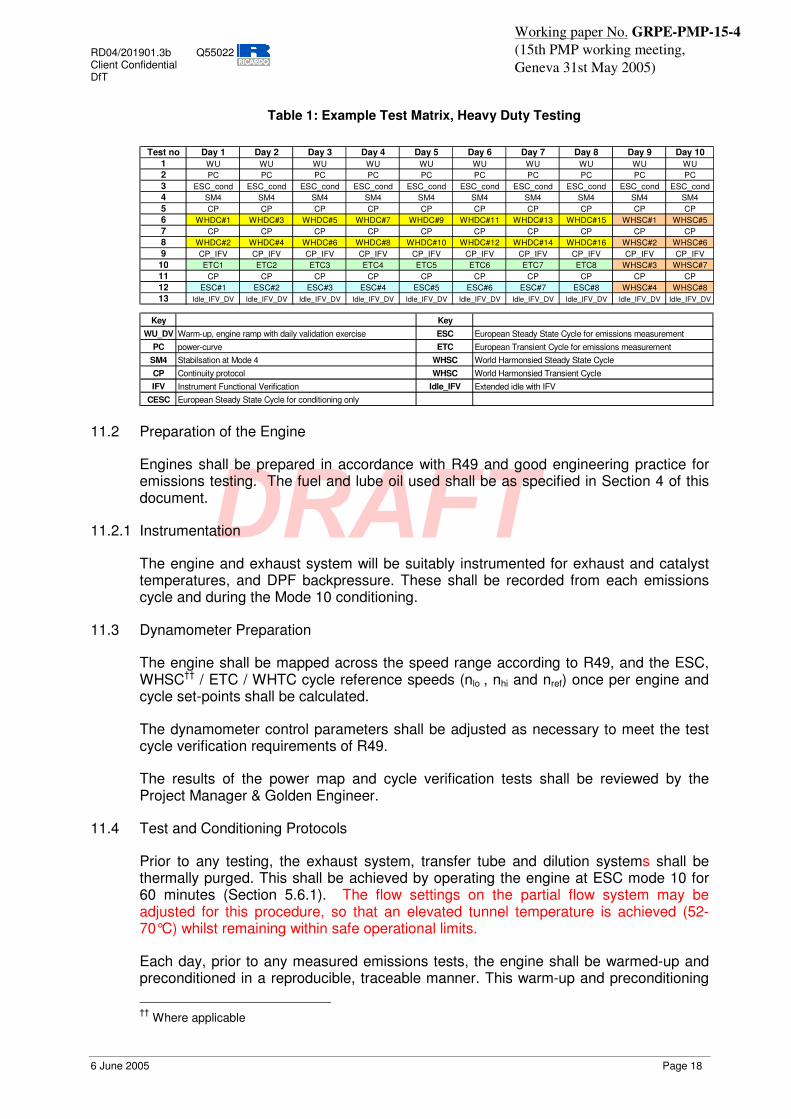
Table 1: Example Test Matrix, Heavy Duty Testing
Test no Day 1 Day 2 Day 3 Day 4 Day 5 Day 6 Day 7 Day 8 Day 9 Day 10
1 WU WU WU WU WU WU WU WU WU WU2 PC PC PC PC PC PC PC PC PC PC3 ESC_cond ESC_cond ESC_cond ESC_cond ESC_cond ESC_cond ESC_cond ESC_cond ESC_cond ESC_cond4 SM4 SM4 SM4 SM4 SM4 SM4 SM4 SM4 SM4 SM45 CP CP CP CP CP CP CP CP CP CP6 WHDC#1 WHDC#3 WHDC#5 WHDC#7 WHDC#9 WHDC#11 WHDC#13 WHDC#15 WHSC#1 WHSC#57 CP CP CP CP CP CP CP CP CP CP8 WHDC#2 WHDC#4 WHDC#6 WHDC#8 WHDC#10 WHDC#12 WHDC#14 WHDC#16 WHSC#2 WHSC#69 CP_IFV CP_IFV CP_IFV CP_IFV CP_IFV CP_IFV CP_IFV CP_IFV CP_IFV CP_IFV
10 ETC1 ETC2 ETC3 ETC4 ETC5 ETC6 ETC7 ETC8 WHSC#3 WHSC#711 CP CP CP CP CP CP CP CP CP CP12 ESC#1 ESC#2 ESC#3 ESC#4 ESC#5 ESC#6 ESC#7 ESC#8 WHSC#4 WHSC#813 Idle_IFV_DV Idle_IFV_DV Idle_IFV_DV Idle_IFV_DV Idle_IFV_DV Idle_IFV_DV Idle_IFV_DV Idle_IFV_DV Idle_IFV_DV Idle_IFV_DV
Key KeyWU_DV Warm-up, engine ramp with daily validation exercise ESC European Steady State Cycle for emissions measurement
PC power-curve ETC European Transient Cycle for emissions measurementSM4 Stabilsation at Mode 4 WHSC World Harmonsied Steady State CycleCP Continuity protocol WHSC World Harmonsied Transient CycleIFV Instrument Functional Verification Idle_IFV Extended idle with IFV
CESC European Steady State Cycle for conditioning only
11.2 Preparation of the Engine
Engines shall be prepared in accordance with R49 and good engineering practice for emissions testing. The fuel and lube oil used shall be as specified in Section 4 of this document.
11.2.1 Instrumentation
The engine and exhaust system will be suitably instrumented for exhaust and catalyst temperatures, and DPF backpressure. These shall be recorded from each emissions cycle and during the Mode 10 conditioning.
11.3 Dynamometer Preparation
The engine shall be mapped across the speed range according to R49, and the ESC, WHSC†† / ETC / WHTC cycle reference speeds (nlo , nhi and nref) once per engine and cycle set-points shall be calculated.
The dynamometer control parameters shall be adjusted as necessary to meet the test cycle verification requirements of R49.
The results of the power map and cycle verification tests shall be reviewed by the Project Manager & Golden Engineer.
11.4 Test and Conditioning Protocols
Prior to any testing, the exhaust system, transfer tube and dilution systems shall be thermally purged. This shall be achieved by operating the engine at ESC mode 10 for 60 minutes (Section 5.6.1). The flow settings on the partial flow system may be adjusted for this procedure, so that an elevated tunnel temperature is achieved (52-70°C) whilst remaining within safe operational limits.
Each day, prior to any measured emissions tests, the engine shall be warmed-up and preconditioned in a reproducible, traceable manner. This warm-up and preconditioning
† † Where applicable

RD04/201901.3b Q55022 Client Confidential DfT
6 June 2005 Page 19
Working paper No. GRPE-PMP-15-4 (15th PMP working meeting, Geneva 31st May 2005)
shall include a power curve, dummy ESC cycle, steady state stabilisation and continuity protocol (Sections 5.6.2, 5.6.4).
Throughout each day’s testing, the engine shall be stabilised between tests through the continuity protocol (Section 5.6.4).
In addition, where appropriate and applicable, periodically regenerating catalyst systems should be subjected to an elective regeneration event 5 minutes into the Mode 4 steady state. This will standardise the condition of the engine and DPF for each test day.
Warm-up and pre-conditioning procedures shall be carried out on the measurement and sampling systems as appropriate. System verification and calibration checks as required shall be performed daily.
An example test protocol for 1 day’s testing is given in Figure 1, Section 5.5.
11.5 Test Procedures – Gaseous Emissions
For the full flow dilution system, gaseous emissions shall be determined from diluted exhaust according to the procedures described in the R49.
Gaseous emissions shall also be determined directly from the raw exhaust according to R49 for steady-state cycles and ISO 16183 for transient cycles.
11.5.1 Preparation for the Test
Prior to the test the gaseous emissions analysers shall be calibrated using suitable reference gases, on the ranges that will be used during the test. The zero and span readings shall be recorded.
11.5.1.1 Partial Flow Dilution only
Prior to the test the response times of the gas analysers and exhaust flow measurement devices shall be determined in accordance with ISO 16183.
11.5.2 During the test
During each test the data from the gaseous emissions analysers shall be recorded with a logging rate of at least 0.5 Hz for the full flow (dilute) analysers, and 2 Hz for the raw emissions analysers.
11.5.2.1 Full flow Dilution only
At the start of the test, the bag-sampling unit shall be switched to start filling the sample and ambient bags.
11.5.3 Post-test : Full flow dilution
At the end of the test the bag sampling unit shall be stopped.
Following the test the zero and span readings of the gaseous emissions analysers shall be checked and recorded. The analysers shall then be calibrated using suitable reference gases, on the ranges that will be used for analysing bag samples. The emissions concentrations in the bag samples shall then be measured and recorded.

RD04/201901.3b Q55022 Client Confidential DfT
6 June 2005 Page 20
Working paper No. GRPE-PMP-15-4 (15th PMP working meeting, Geneva 31st May 2005)
11.6 Test Procedures – Particulate Emissions: Full and Partial Flow
11.6.1 Preparation of the Partial Flow Dilution System
Prior to the test, the flow settings for the partial flow dilution system shall be determined, as required to meet the sampling requirements of Section 8. If necessary, a pre-test cycle shall be run and the exhaust flow data recorded by the partial flow sampling system.
11.6.2 Preparation for the Test (filter weighing, switch to bypass)
Prior to the test the test filters shall be conditioned in the weighing room. The initial filter masses shall be measured and recorded on a microbalance with 1µg or better resolution.
During the system stabilisation procedure, the particulate sampling systems shall be operated on bypass.
11.6.3 During the test (switch to sample)
At the start of the test, the particulate sampling systems shall be switched from the bypass to the sample filters.
11.6.4 Post-test (condition and weigh filters)
On completion of the test, the particulate sampling systems shall be stopped. The filter holders shall be removed and the filters returned to the weighing room or chamber for conditioning.
After conditioning the filters shall be weighed and the masses recorded.
11.7 Test Procedures – Particle Emissions
The following sections describe the procedures that shall be followed by each laboratory in receiving, installing and operating the Golden Particle Measurement Systems.
11.7.1 Equipment Arrival at Laboratory
On arrival at the laboratory, all equipment shall be unpacked and inspected for damage. If any components are missing or damaged the Golden Engineer and Project Manager shall be informed.
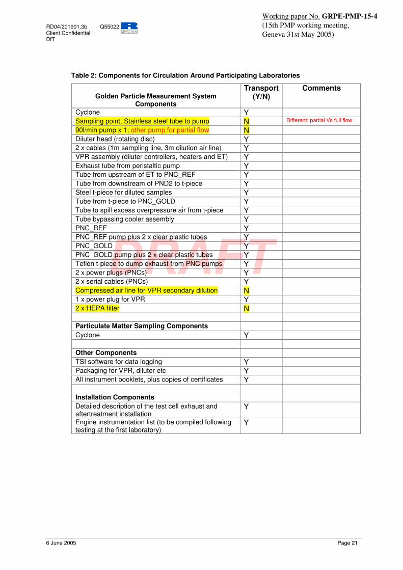
11.7.2 List Of Equipment/Components
The equipment accompanying the Golden Engine that will be circulated between laboratories is summarised in Table 2. Duplicate copies of all components detailed in this table will be supplied.
RD04/201901.3b Q55022 Client Confidential DfT
6 June 2005 Page 21
Working paper No. GRPE-PMP-15-4 (15th PMP working meeting, Geneva 31st May 2005)
Table 2: Components for Circulation Around Participating Laboratories
Golden Particle Measurement System
Components
Transport (Y/N)
Comments
Cyclone Y Sampling point, Stainless steel tube to pump N Different: partial Vs full flow
90l/min pump x 1; other pump for partial flow N Diluter head (rotating disc) Y 2 x cables (1m sampling line, 3m dilution air line) Y VPR assembly (diluter controllers, heaters and ET) Y Exhaust tube from peristaltic pump Y Tube from upstream of ET to PNC_REF Y Tube from downstream of PND2 to t-piece Y Steel t-piece for diluted samples Y Tube from t-piece to PNC_GOLD Y Tube to spill excess overpressure air from t-piece Y Tube bypassing cooler assembly Y PNC_REF Y PNC_REF pump plus 2 x clear plastic tubes Y PNC_GOLD Y PNC_GOLD pump plus 2 x clear plastic tubes Y Teflon t-piece to dump exhaust from PNC pumps Y 2 x power plugs (PNCs) Y 2 x serial cables (PNCs) Y Compressed air line for VPR secondary dilution N 1 x power plug for VPR Y 2 x HEPA filter N Particulate Matter Sampling Components Cyclone Y Other Components TSI software for data logging Y Packaging for VPR, diluter etc Y All instrument booklets, plus copies of certificates Y Installation Components Detailed description of the test cell exhaust and aftertreatment installation
Y
Engine instrumentation list (to be compiled following testing at the first laboratory)
Y
RD04/201901.3b Q55022 Client Confidential DfT
6 June 2005 Page 22
Working paper No. GRPE-PMP-15-4 (15th PMP working meeting, Geneva 31st May 2005)
11.7.3 Initial Checks and Assembly of GPMS [For each system]
A PNC linearity check will be carried out on PNC_GOLD and PNC_REF simultaneously. The purpose of this procedure is to verify the similarity of the counters and their responses across the concentration range of interest. Using an aerosol source with an initial concentration of less than 100000/cm3, and a calibrated diluter supplied as part of the GPMS, five dilution factors spanning at least a factor of 20 shall be selected: for example; 300, 200, 100, 50, 15. The R2 (correlation coefficient) value of the five concentration values obtained shall then be compared with the R2 value from the CPC_GOLD calibration certificate. Linearity of response is calculated as the square of the Pearson product moment correlation coefficient (R2) of the two data sets and shall be equal to or greater than 0.95.
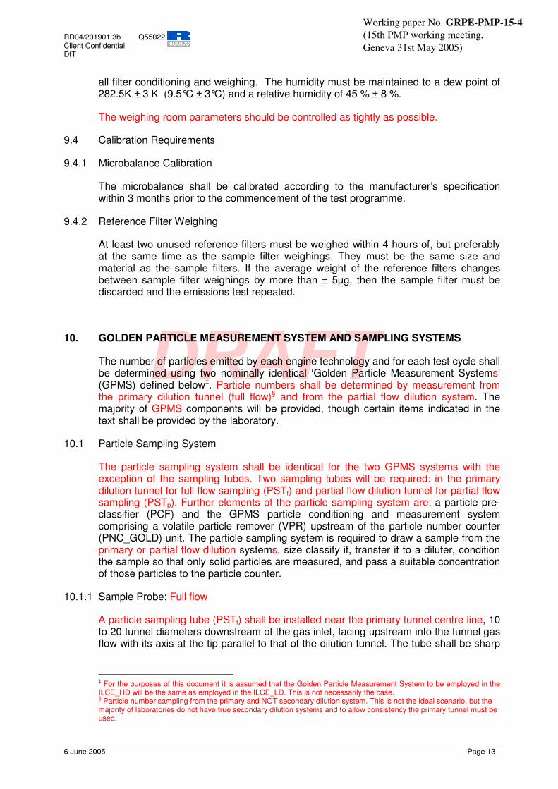
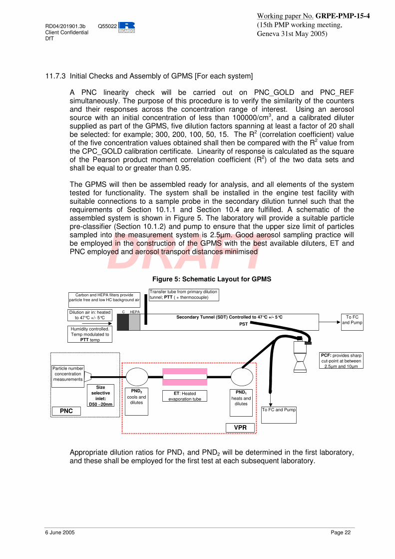
The GPMS will then be assembled ready for analysis, and all elements of the system tested for functionality. The system shall be installed in the engine test facility with suitable connections to a sample probe in the secondary dilution tunnel such that the requirements of Section 10.1.1 and Section 10.4 are fulfilled. A schematic of the assembled system is shown in Figure 5. The laboratory will provide a suitable particle pre-classifier (Section 10.1.2) and pump to ensure that the upper size limit of particles sampled into the measurement system is 2.5µm. Good aerosol sampling practice will be employed in the construction of the GPMS with the best available diluters, ET and PNC employed and aerosol transport distances minimised
Figure 5: Schematic Layout for GPMS
C HEPASecondary Tunnel (SDT) Controlled to 47°C +/- 5°C
To FC and Pump
PCF: provides sharp cut-point at between
2.5µm and 10µm
Carbon and HEPA filters provide particle free and low HC background air
PND1
heats and dilutes
Particle number concentration
measurements
ET: Heatedevaporation tube
Dilution air in: heated to 47°C +/- 5°C
Humidity controlled. Temp modulated to
PTT temp
To FC and Pump
Size selective
inlet:D50 ~20nm
PND2
cools and dilutes
VPR
PST
Transfer tube from primary dilution tunnel; PTT ( + thermocouple)
PNC
Appropriate dilution ratios for PND1 and PND2 will be determined in the first laboratory, and these shall be employed for the first test at each subsequent laboratory.

RD04/201901.3b Q55022 Client Confidential DfT
6 June 2005 Page 23
Working paper No. GRPE-PMP-15-4 (15th PMP working meeting, Geneva 31st May 2005)
11.7.4 Preparation for Daily Protocol: Instrument Warm-up and Daily Verification Exercises
First thing each morning all the elements of the measurement systems will be activated, and left for at least 30 minutes to stabilise. This includes pumps, heaters, diluters and particle counters. The temperature of heated sections will be inspected to ensure compliance with the requirements of Section 8.2.2.
Instrument manufacturers of the various elements of the GPMS will provide calibration certification for the diluter(s), evaporation tube and particle counter employed for PMP particle number measurements. These data will be appropriate to address those requirements for primary calibration of instrumentation defined in the draft R49 regulation. However, it should be noted that the regulations are drafted with the intention that instrument manufacturers will have time to develop entirely suitable equipment and at this time exact compliance of all instrumentation with the draft regulations may not be possible.
Therefore the main issues are that operation consistent with the baseline calibrations is ensured, and that repeatable and valid operation can be demonstrated and maintained. In order to ensure this, regular calibration checks shall be performed. These are summarised as follows:
11.7.4.1 Verification of Free Sample Flow and Flow rate – The GPMS shall be checked for physical blockages and the CPC flow rate checked. The measured flow rate shall be within 5% of the instrument’s nominal value.
11.7.4.2 Verification of Counter Zero – An initial concentration of around 10000/cm3 (e.g. background number concentration) will be applied to both PNCs via a HEPA filter and using clean, particle free tubing. Testing shall commence if the measured particle count is less than 1/cm3.
11.7.4.3 Verification of Counter High Response – Background particle concentration will be simultaneously sampled into both PNC_GOLD and PNC_REF. Testing may commence when a comparable response is observed from both PNCs. If the source aerosol shows a concentration above 104cm-3, a diluter may be employed to reduce the concentration introduced to the CPCs.
11.7.4.4 Verification of System Contamination and Leak Integrity – After heating the evaporation tube a HEPA filter will be applied to the inlet of the diluter and particle number concentration through the whole system measured using PNC_GOLD. Testing can commence providing the measured particle count is less than 5/cm3.
The GPMS shall then be fully reassembled. A sample line connected downstream of the particle pre-classifier shall then be connected to the inlet of the VPR. Sampling shall commence.
Any problems encountered during the daily verification exercise should be referred to the Golden Engineer or Project Manager who will make a decision on whether to proceed with the test programme.
RD04/201901.3b Q55022 Client Confidential DfT
6 June 2005 Page 24
Working paper No. GRPE-PMP-15-4 (15th PMP working meeting, Geneva 31st May 2005)
11.8 During the test
During each emissions test, particle number concentrations from both PNC_Gold and PNC_REF shall be measured continuously in the particle sampling system with a frequency of >=0.5 Hz. The average concentrations shall be determined by integrating the analyser signals over the test cycle, with data recorded electronically. The system response time shall be ����V��DQG�VKDOO�EH�FR-ordinated with primary tunnel (CVS) flow fluctuations and sampling time/test cycle offsets, if necessary.
11.9 Post-test
The following instrument function verification tests will be performed according to the demands to the daily test protocol:
Verification of Free Sample Flow – The GPMS shall be checked for physical blockages. (Section 11.7.4.1). The PNC flow rate will be checked.
Verification of Counter Zero – An initial concentration of around 10000/cm3 (e.g. background number concentration) will be applied to both PNCs via a HEPA filter and using clean, particle free tubing. Testing shall commence if the measured particle count is less than 1/cm3. (Section 11.7.4.2)
Verification of Counter High Response – Background particle concentration will be simultaneously sampled into both PNC_GOLD and PNC_REF. If background concentration is >104cm-3 dilution may be employed to reduce the concentration. Testing may commence when a comparable response is observed from both PNCs. (9.10.4.3).
Data from each test will be inspected to determine whether instantaneous concentrations at the PNC_GOLD have exceeded 104 particles cm/3 during the emissions cycle. If this has occurred, the dilution ratios of PND1 and PND2 may need to be modified. These modifications shall be discussed with and approved by the project manager or golden engineer prior to the next test on that engine.
If necessary, the PND1 and PND2 diluters should be cleaned at this stage. It is not anticipated that this will be required with tests on a DPF equipped engine, but laboratories testing conventional diesels may encounter contamination issues.
11.9.1 Repeat Daily Verification Exercise
Following the first block of tests, correct VPR functional temperatures will be established and the checks described in Sections 11.7.4.1 to 11.7.4.4 inclusive conducted.
11.10 On Completion Of The Test Matrix
On completion of all testing, the GPMS and engines will be prepared for despatch to the next laboratory for testing.
However, prior to testing at the first laboratory and subsequent to testing at some additional laboratories, the VPR will be returned to a calibration facility for a performance check. This check will determine the penetration and volatile removal performance of the VPR as described below:
RD04/201901.3b Q55022 Client Confidential DfT
6 June 2005 Page 25
Working paper No. GRPE-PMP-15-4 (15th PMP working meeting, Geneva 31st May 2005)
Verification of VPR Function – The removal of at least 99% of a volatile test aerosol where the initial concentration is >10,000/cm3 and concentration downstream of the thermoconditioner is >100/cm3 shall be demonstrated. A polydisperse volatile aerosol of modal diameter between 20 and 60nm will be generated using a suitable aerosol generator. Measurements will be made before and after the thermoconditioner using a PNC.
VPR Penetration - A second verification is to demonstrate that the solid particle (a particle that is not volatile under the VPR operating conditions) penetration through the VPR conforms to the manufacturer’s specification. A polydisperse aerosol will be classified in order to produce solid particles with a modal diameter of 60nm and passed through the VPR. Measurements will be made pre- and post-VPR at 20:1 and 300:1 dilution settings, and the actual penetration determined and recorded.
These performance evaluations will be undertaken during the shipping process for the Golden Vehicle and shall not delay the test programme. The decision as to when the VPR will be returned to the calibration facility will depend on the number of participating laboratories and will be at the discretion of the project manager and Golden Engineer.
12. DATA CAPTURE AND PRESENTATION IN CORRECT FORMAT
All data will be presented in a format compatible with Microsoft Excel. A standard spreadsheet for these data will be provided, prior to the commencement of testing, by the Project manager.
12.1 Regulated Emissions
Summary regulated gaseous emissions, carbon dioxide and fuel consumption data shall be quoted as g/kWh according to current European regulations. Data will be presented from complete ETC cycles as well as ESC and steady states where appropriate.
12.2 Particulate Mass
Summary particulate mass data shall be quoted as g/kWh according to current European regulations. Data will be presented from the complete ETC cycle.
12.3 Particle Number
Summary particle number data shall be quoted as number/kWh and number/s. Data will be presented from individual urban, rural and motorway phases and from the combined, ETC cycle.
Data from the ESC cycle shall be presented per mode in particles/s and per kWh for the weighted cycle.
Steady state data shall be presented in particles/s and particles/kWh.
In addition, logged particle number data, time-aligned and synchronised with the regulated gaseous emissions shall be presented in a time-aligned format on a CD-R.
RD04/201901.3b Q55022 Client Confidential DfT
6 June 2005 Page 26
Working paper No. GRPE-PMP-15-4 (15th PMP working meeting, Geneva 31st May 2005)
12.4 Diagnostic Data
Testbed data shall be logged continuously throughout each test at a rate of at least 1Hz in order to provide diagnostic capability if repeatability or reproducibility of engine tests is poor. These data shall be employed to interpret catalytic activity and engine management control. All logged data shall be presented in a time-aligned format on a CD-R. As a minimum these data shall include:
� engine speed and torque
� intake, exhaust and catalyst temperatures and pressures
� coolant and oil temperatures and pressures
� DPF backpressure
� dilute gaseous emissions and CVS flow rate
� raw gaseous emissions and exhaust / air / fuel flow rate
� partial flow dilution system sample flow rate

RD04/201901.3b Q55022 Client Confidential DfT
6 June 2005 Page 27
Working paper No. GRPE-PMP-15-4 (15th PMP working meeting, Geneva 31st May 2005)
Appendix 1: Lubricant Change, Flush and Conditioning Protocol
� Commence oil drain � Allow drain to continue until flow stops � Fill with 15 +/ - 1 litre of replacement oil � Start engine and idle (ESC Mode 1) for 30 seconds � Run the engine up to ESC mode 4 � Allow the engine speed and load to settle for ~15 seconds � Return to idle and allow to settle ~15 seconds � Repeat the ESC Mode 4 / Idle cycling 5 times � Drain the oil down and remove the oil filter. � Refill with 15 litres of new oil and new filter filled with oil � Condition at ESC Mode 10 for 1 hr.