UMX Radian - modelflight.com.au
15
Instruction Manual Bedienungsanleitung Manuel d’utilisation Manuale di Istruzioni UMX Radian ™ ®
Transcript of UMX Radian - modelflight.com.au
Instruction ManualBedienungsanleitungManuel d’utilisationManuale di Istruzioni
UMX Radian ™ ®
EN
UMX Radian2
Safety Precautions and WarningsAs the user of this product, you are solely responsible for operating in a manner that does not endanger yourself and others or result in damage to the product or the property of others.
• Always keep a safe distance in all directions around your model to avoid collisions or injury. This model is controlled by a radio signal subject to interference from many sources outside your control. Interference can cause momentary loss of control.
• Always operate your model in open spaces away from full-size vehicles, traffic and people.
• Always carefully follow the directions and warnings for this and any optional support equipment (chargers, rechargeable battery packs, etc.).
• Always keep all chemicals, small parts and anything electrical out of the reach of children.
• Always avoid water exposure to all equipment not specifically designed and protected for this purpose. Moisture causes damage to electronics.
• Never place any portion of the model in your mouth as it could cause serious injury or even death.
• Never operate your model with low transmitter batteries.• Always keep aircraft in sight and under control.• Always use fully charged batteries.• Always keep transmitter powered on while aircraft is
powered.• Always remove batteries before disassembly.• Always keep moving parts clean.• Always keep parts dry.• Always let parts cool after use before touching.• Always remove batteries after use.• Always ensure failsafe is properly set before flying.• Never operate aircraft with damaged wiring.• Never touch moving parts.
WARNING: Read the ENTIRE instruction manual to become familiar with the features of the product before operating. Failure to operate the product correctly can result in damage to the product, personal property and
cause serious injury. This is a sophisticated hobby product. It must be operated with caution and common sense and requires some basic mechanical ability. Failure to operate this Product in a safe and responsible manner could result in injury or damage to the product or other property. This product is not intended for use by children without direct adult supervision. Do not use with incompatible components or alter this product in any way outside of the instructions provided by Horizon Hobby, LLC. This manual contains instructions for safety, operation and maintenance. It is essential to read and follow all the instructions and warnings in the manual, prior to assembly, setup or use, in order to operate correctly and avoid damage or serious injury.
AGE RECOMMENDATION: Not for children under 14 years. This is not a toy.
NOTICEAll instructions, warranties and other collateral documents are subject to change at the sole discretion of Horizon Hobby, LLC. For up-to-date product literature, visit horizonhobby.com or towerhobbies.com and click on the support or resources tab for this product.
MEANING OF SPECIAL LANGUAGEThe following terms are used throughout the product literature to indicate various levels of potential harm when operating this product:WARNING: Procedures, which if not properly followed, create the probability of property damage, collateral damage, and serious injury OR create a high probability of superficial injury.CAUTION: Procedures, which if not properly followed, create the probability of physical property damage AND a possibility of serious injury.NOTICE: Procedures, which if not properly followed, create a possibility of physical property damage AND little or no possibility of injury.
EN
3
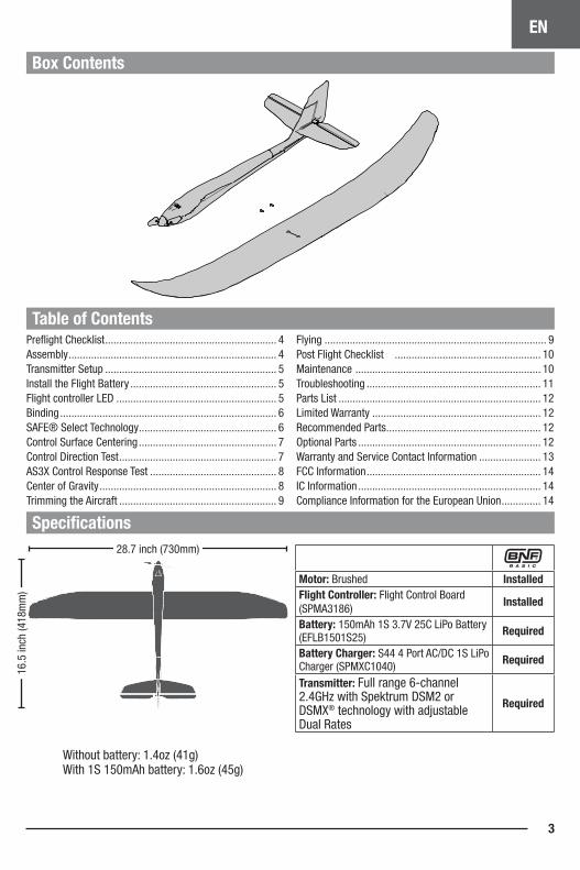
Specifications
Box Contents
Table of Contents
28.7 inch (730mm)
16.5
inch
(418
mm
)
Preflight Checklist ............................................................. 4Assembly .......................................................................... 4Transmitter Setup ............................................................. 5Install the Flight Battery .................................................... 5Flight controller LED ......................................................... 5Binding ............................................................................. 6SAFE® Select Technology ................................................. 6Control Surface Centering ................................................. 7Control Direction Test ........................................................ 7AS3X Control Response Test ............................................. 8Center of Gravity ............................................................... 8Trimming the Aircraft ........................................................ 9
Flying ............................................................................... 9Post Flight Checklist .................................................... 10Maintenance .................................................................. 10Troubleshooting .............................................................. 11Parts List ........................................................................ 12Limited Warranty ............................................................ 12Recommended Parts ....................................................... 12Optional Parts ................................................................. 12Warranty and Service Contact Information ...................... 13FCC Information .............................................................. 14IC Information ................................................................. 14Compliance Information for the European Union .............. 14
Wi thout battery: 1.4oz (41g) Wi th 1S 150mAh battery: 1.6oz (45g)
Motor: Brushed InstalledFlight Controller: Flight Control Board (SPMA3186)
Installed
Battery: 150mAh 1S 3.7V 25C LiPo Battery (EFLB1501S25) Required
Battery Charger: S44 4 Port AC/DC 1S LiPo Charger (SPMXC1040) Required
Transmitter: Full range 6-channel 2.4GHz with Spektrum DSM2 or DSMX® technology with adjustable Dual Rates
Required
EN
UMX Radian4
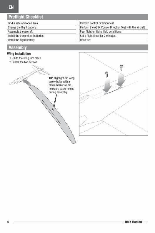
Find a safe and open area.Charge the flight battery.Assemble the aircraft.Install the transmitter batteries.Install the flight battery.
Perform control direction test.Perform the AS3X Control Direction Test with the aircraft.Plan flight for flying field conditions.Set a flight timer for 7 minutes.Have fun!
Assembly
Preflight Checklist
Wing Installation1. Slide the wing into place.2. Install the two screws.
TIP: Highlight the wing screw holes with a black marker so the holes are easier to see during assembly.
EN
5
Transmitter Setup
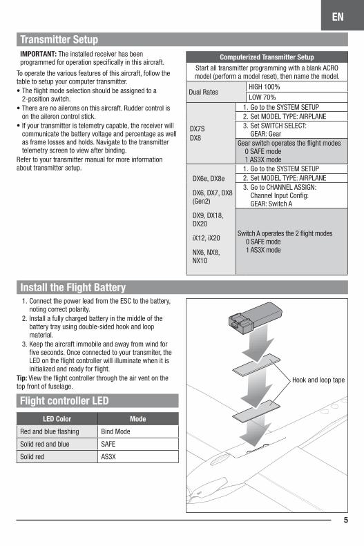
Install the Flight Battery
Hook and loop tape
1. Connect the power lead from the ESC to the battery, noting correct polarity.
2. Install a fully charged battery in the middle of the battery tray using double-sided hook and loop material.
3. Keep the aircraft immobile and away from wind for five seconds. Once connected to your transmiter, the LED on the flight controller will illuminate when it is initialized and ready for flight.
Tip: View the flight controller through the air vent on the top front of fuselage.
Flight controller LED
LED Color Mode
Red and blue flashing Bind Mode
Solid red and blue SAFE
Solid red AS3X
IMPORTANT: The installed receiver has been programmed for operation specifically in this aircraft.
To operate the various features of this aircraft, follow the table to setup your computer transmitter.• The flight mode selection should be assigned to a
2-position switch.• There are no ailerons on this aircraft. Rudder control is
on the aileron control stick. • If your transmitter is telemetry capable, the receiver will
communicate the battery voltage and percentage as well as frame losses and holds. Navigate to the transmitter telemetry screen to view after binding.
Refer to your transmitter manual for more information about transmitter setup.
Computerized Transmitter SetupStart all transmitter programming with a blank ACRO model (perform a model reset), then name the model.
Dual RatesHIGH 100%
LOW 70%
DX7SDX8
1. Go to the SYSTEM SETUP2. Set MODEL TYPE: AIRPLANE3. Set SWITCH SELECT:
GEAR: GearGear switch operates the flight modes 0 SAFE mode 1 AS3X mode
DX6e, DX8e
DX6, DX7, DX8 (Gen2)
DX9, DX18, DX20
iX12, iX20
NX6, NX8, NX10
1. Go to the SYSTEM SETUP2. Set MODEL TYPE: AIRPLANE 3. Go to CHANNEL ASSIGN:
Channel Input Config: GEAR: Switch A
Switch A operates the 2 flight modes 0 SAFE mode 1 AS3X mode
EN
UMX Radian6
SAFE® Select Technology
Mode 1 and 2 transmitters
X 5100%
100%
When SAFE Select is activated, bank and pitch limitations keep you from over-controlling the aircraft. Additionally, by releasing the controls in the event you lose orientation, SAFE Select will keep the aircraft level.To activate SAFE® Select, flip the Gear channel switch to position 0. Return the Gear switch to position 1 to turn OFF SAFE Select and fly with just the assistance of AS3X® technology.If you become disoriented or the aircraft is in a confusing attitude, flip the Gear switch to position 0 and release the sticks. With the elevator and rudder stick in the neutral position, SAFE Select will automatically keep the airplane in a straight and level attitude.
Disabling and Enabling SAFE SelectBy default, the SAFE Select function of your UMX aircraft is enabled and assigned to the Gear channel switch (channel 5). If you do not wish to have access to SAFE Select while flying, you can choose to disable SAFE Select functionality. AS3X will still be active when SAFE Select is disabled.IMPORTANT: Before attempting to disable or enable SAFE Select, ensure the aileron, elevator, rudder, throttle and gear channels are all on high rate with the travel set to 100%. Turn throttle hold OFF if it is programmed in the transmitter.
CAUTION: Keep all body parts clear of the propeller and keep the aircraft securely restrained in case of accidental throttle activation.
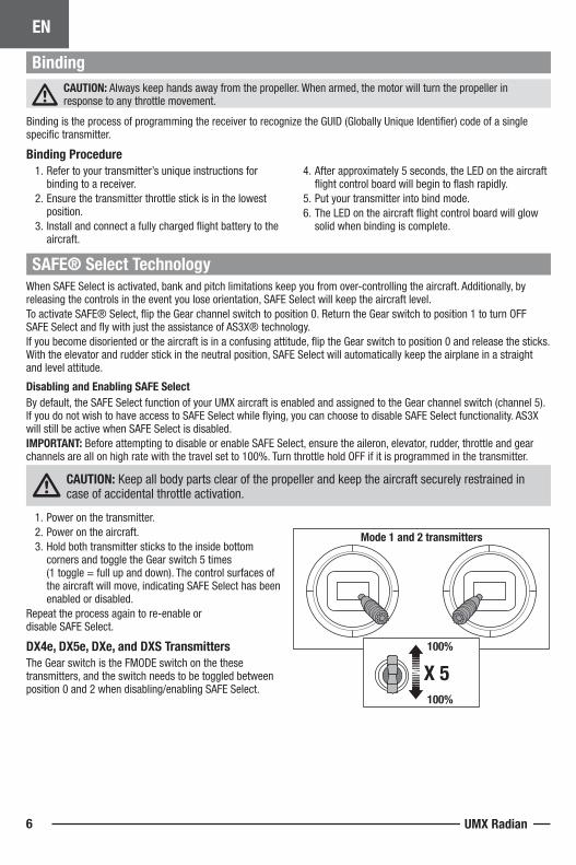
1. Power on the transmitter.2. Power on the aircraft.3. Hold both transmitter sticks to the inside bottom
corners and toggle the Gear switch 5 times (1 toggle = full up and down). The control surfaces of the aircraft will move, indicating SAFE Select has been enabled or disabled.
Repeat the process again to re-enable or disable SAFE Select.
DX4e, DX5e, DXe, and DXS TransmittersThe Gear switch is the FMODE switch on the these transmitters, and the switch needs to be toggled between position 0 and 2 when disabling/enabling SAFE Select.
BindingCAUTION: Always keep hands away from the propeller. When armed, the motor will turn the propeller in response to any throttle movement.
Binding is the process of programming the receiver to recognize the GUID (Globally Unique Identifier) code of a single specific transmitter.
Binding Procedure1. Refer to your transmitter’s unique instructions for
binding to a receiver.2. Ensure the transmitter throttle stick is in the lowest
position.3. Install and connect a fully charged flight battery to the
aircraft.
4. After approximately 5 seconds, the LED on the aircraft flight control board will begin to flash rapidly.
5. Put your transmitter into bind mode.6. The LED on the aircraft flight control board will glow
solid when binding is complete.
EN
7
Control Surface Centering
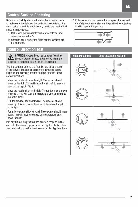
Control Direction TestStick Movement Control Surface Reaction
Before your first flights, or in the event of a crash, check to make sure the flight control surfaces are centered. It is much better to do this mechanically due to the mechanical limits of linear servos.
1. Make sure the transmitter trims are centered, and sub-trims are set to 0.
2. Check to see if any of the flight control surfaces are not centered.
3. If the surface is not centered, use a pair of pliers and carefully lengthen or shorten the pushrod by adjusting the U-shape in the pushrod.
If at any time during the test the controls respond in the opposite direction of operation of the flight controls, follow your transmitter’s instructions to reverse the flight controls.
CAUTION: Always keep hands away from the propeller. When armed, the motor will turn the
propeller in response to any throttle movement.
Test the controls prior to the first flight to ensure none of the servos, linkages or parts were damaged during shipping and handling and the controls function in the correct directions.
Move the rudder stick to the right. The rudder should move to the right. This will cause the aircraft to yaw and bank to the right in flight.
Move the rudder stick to the left. The rudder should move to the left. This will cause the aircraft to yaw and bank to the left in flight.
Pull the elevator stick backward. The elevator should move up. This will cause the nose of the aircraft to pitch up in flight.
Push the elevator stick forward. The elevator should move down. This will cause the nose of the aircraft to pitch down in flight.
EN
UMX Radian8
22-28mm
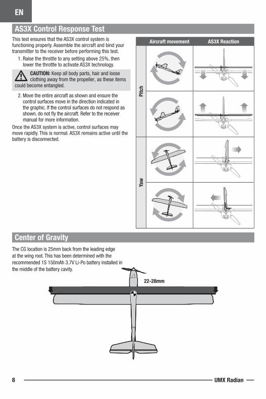
AS3X Control Response TestThis test ensures that the AS3X control system is functioning properly. Assemble the aircraft and bind your transmitter to the receiver before performing this test.
1. Raise the throttle to any setting above 25%, then lower the throttle to activate AS3X technology.
CAUTION: Keep all body parts, hair and loose clothing away from the propeller, as these items
could become entangled.
2. Move the entire aircraft as shown and ensure the control surfaces move in the direction indicated in the graphic. If the control surfaces do not respond as shown, do not fly the aircraft. Refer to the receiver manual for more information.
Once the AS3X system is active, control surfaces may move rapidly. This is normal. AS3X remains active until the battery is disconnected.
Aircraft movement AS3X Reaction
Pitc
hYa
w
Center of GravityThe CG location is 25mm back from the leading edgeat the wing root. This has been determined with therecommended 1S 150mAh 3.7V Li-Po battery installed inthe middle of the battery cavity.
EN
9
Trimming the Aircraft
FlyingConsult local laws and ordinances before choosing a location to fly your aircraft.
WARNING: The motor will become hot during normal use. Do not touch the motor until it has cooled.
We recommend flying your aircraft outside in no greater than 10mph winds or inside in a large gymnasium. Always avoid flying near houses, trees, wires and buildings.Avoid flying in areas where there are many people, such as busy parks, schoolyards or soccer fields. Set a timer for 7 minutes.
Hand LaunchingTo hand launch the aircraft, hold the fuselage under the wings. Advance to full throttle and give the aircraft a firm throw, slightly up (5–10 degrees above the horizon), and directly into the wind. After the model gains altitude and speed, decrease the throttle and trim the aircraft for level flightwhen in AS3X flight mode.
LandingAlways land into the wind. Reduce throttle to zero and allow the aircraft to settle into a glide path. During landing approach keep the wings level and the aircraft pointed into the wind. As the aircraft settles close to the ground, ease back on the elevator to flare for landing.
NOTICE: Always fully lower the throttle at touch down when landing the aircraft. Failure to lower the throttle stick and trim to the lowest possible positions during a crash could result in damage to the ESC in the receiver unit or to the propeller shaft.
Crash damage is not covered under warranty.
RepairsRepair this aircraft using foam safe CA glue or clear tape. When parts are not repairable, see the Replacement Parts List for ordering by item number.
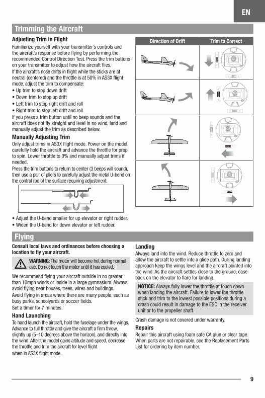
Direction of Drift Trim to CorrectAdjusting Trim in FlightFamiliarize yourself with your transmitter’s controls and the aircraft’s response before flying by performing the recommended Control Direction Test. Press the trim buttons on your transmitter to adjust how the aircraft flies.If the aircraft’s nose drifts in flight while the sticks are at neutral (centered) and the throttle is at 50% in AS3X flight mode, adjust the trim to compensate:• Up trim to stop down drift • Down trim to stop up drift • Left trim to stop right drift and roll• Right trim to stop left drift and rollIf you press a trim button until no beep sounds and the aircraft does not fly straight and level in no wind, land and manually adjust the trim as described below.
Manually Adjusting TrimOnly adjust trims in AS3X flight mode. Power on the model, carefully hold the aircraft and advance the throttle for prop to spin. Lower throttle to 0% and manually adjust trims if needed. Press the trim buttons to return to center (3 beeps will sound), then use a pair of pliers to carefully adjust the metal U-bend on the control rod of the surface requiring adjustment:
• Adjust the U-bend smaller for up elevator or right rudder.• Widen the U-bend for down elevator or left rudder.
EN
UMX Radian10
Post Flight Checklist
Maintenance
Disconnect the flight battery from the ESC.
Power OFF the transmitter.
Remove the flight battery from the aircraft.
Recharge the flight battery.
Repair or replace all damaged parts.
Store the flight battery apart from the aircraft and monitor the battery charge.
Make note of the flight conditions and flight plan results, planning for future flights.
WARNING: Do not perform this or any other equipment maintenance with the propeller installed on the aircraft. Serious injury or property damage could result from the motor starting inadvertently.
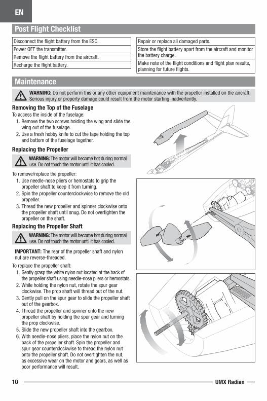
Removing the Top of the FuselageTo access the inside of the fuselage:
1. Remove the two screws holding the wing and slide the wing out of the fuselage.
2. Use a fresh hobby knife to cut the tape holding the top and bottom of the fuselage together.
Replacing the Propeller WARNING: The motor will become hot during normal use. Do not touch the motor until it has cooled.
To remove/replace the propeller:1. Use needle-nose pliers or hemostats to grip the
propeller shaft to keep it from turning.2. Spin the propeller counterclockwise to remove the old
propeller.3. Thread the new propeller and spinner clockwise onto
the propeller shaft until snug. Do not overtighten the propeller on the shaft.
Replacing the Propeller Shaft WARNING: The motor will become hot during normal use. Do not touch the motor until it has cooled.
IMPORTANT: The rear of the propeller shaft and nylon nut are reverse-threaded.
To replace the propeller shaft:1. Gently grasp the white nylon nut located at the back of
the propeller shaft using needle-nose pliers or hemostats.2. While holding the nylon nut, rotate the spur gear
clockwise. The prop shaft will thread out of the nut.3. Gently pull on the spur gear to slide the propeller shaft
out of the gearbox.4. Thread the propeller and spinner onto the new
propeller shaft by holding the spur gear and turning the prop clockwise.
5. Slide the new propeller shaft into the gearbox.6. With needle-nose pliers, place the nylon nut on the
back of the propeller shaft. Spin the propeller and spur gear counterclockwise to thread the nylon nut onto the propeller shaft. Do not overtighten the nut, as excessive wear on the motor and gears, as well as poor performance will result.
EN
11
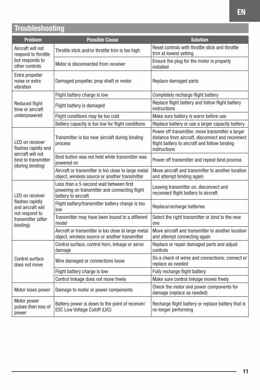
TroubleshootingProblem Possible Cause Solution
Aircraft will not respond to throttle but responds to other controls
Throttle stick and/or throttle trim is too high Reset controls with throttle stick and throttle trim at lowest setting
Motor is disconnected from receiver Ensure the plug for the motor is properly installed
Extra propeller noise or extra vibration
Damaged propeller, prop shaft or motor Replace damaged parts
Reduced flight time or aircraft underpowered
Flight battery charge is low Completely recharge flight battery
Flight battery is damaged Replace flight battery and follow flight battery instructions
Flight conditions may be too cold Make sure battery is warm before use
Battery capacity is too low for flight conditions Replace battery or use a larger capacity battery
LED on receiver flashes rapidly and aircraft will not bind to transmitter (during binding)
Transmitter is too near aircraft during binding process
Power off transmitter, move transmitter a larger distance from aircraft, disconnect and reconnect flight battery to aircraft and follow binding instructions
Bind button was not held while transmitter was powered on Power off transmitter and repeat bind process
Aircraft or transmitter is too close to large metal object, wireless source or another transmitter
Move aircraft and transmitter to another location and attempt binding again
LED on receiver flashes rapidly and aircraft will not respond to transmitter (after binding)
Less than a 5-second wait between first powering on transmitter and connecting flight battery to aircraft
Leaving transmitter on, disconnect and reconnect flight battery to aircraft
Flight battery/transmitter battery charge is too low Replace/recharge batteries
Transmitter may have been bound to a different model
Select the right transmitter or bind to the new one
Aircraft or transmitter is too close to large metal object, wireless source or another transmitter
Move aircraft and transmitter to another location and attempt connecting again
Control surface does not move
Control surface, control horn, linkage or servo damage
Replace or repair damaged parts and adjust controls
Wire damaged or connections loose Do a check of wires and connections; connect or replace as needed
Flight battery charge is low Fully recharge flight battery
Control linkage does not move freely Make sure control linkage moves freely
Motor loses power Damage to motor or power components Check the motor and power components for damage (replace as needed)
Motor power pulses then loss of power
Battery power is down to the point of receiver/ESC Low Voltage Cutoff (LVC)
Recharge flight battery or replace battery that is no longer performing
EN
UMX Radian12
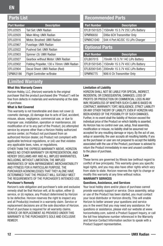
What this Warranty CoversHorizon Hobby, LLC, (Horizon) warrants to the original purchaser that the product purchased (the “Product”) will be free from defects in materials and workmanship at the date of purchase.What is Not CoveredThis warranty is not transferable and does not cover (i) cosmetic damage, (ii) damage due to acts of God, accident, misuse, abuse, negligence, commercial use, or due to improper use, installation, operation or maintenance, (iii) modification of or to any part of the Product, (iv) attempted service by anyone other than a Horizon Hobby authorized service center, (v) Product not purchased from an authorized Horizon dealer, (vi) Product not compliant with applicable technical regulations, or (vii) use that violates any applicable laws, rules, or regulations. OTHER THAN THE EXPRESS WARRANTY ABOVE, HORIZON MAKES NO OTHER WARRANTY OR REPRESENTATION, AND HEREBY DISCLAIMS ANY AND ALL IMPLIED WARRANTIES, INCLUDING, WITHOUT LIMITATION, THE IMPLIED WARRANTIES OF NON-INFRINGEMENT, MERCHANTABILITY AND FITNESS FOR A PARTICULAR PURPOSE. THE PURCHASER ACKNOWLEDGES THAT THEY ALONE HAVE DETERMINED THAT THE PRODUCT WILL SUITABLY MEET THE REQUIREMENTS OF THE PURCHASER’S INTENDED USE.Purchaser’s RemedyHorizon’s sole obligation and purchaser’s sole and exclusive remedy shall be that Horizon will, at its option, either (i) service, or (ii) replace, any Product determined by Horizon to be defective. Horizon reserves the right to inspect any and all Product(s) involved in a warranty claim. Service or replacement decisions are at the sole discretion of Horizon. Proof of purchase is required for all warranty claims. SERVICE OR REPLACEMENT AS PROVIDED UNDER THIS WARRANTY IS THE PURCHASER’S SOLE AND EXCLUSIVE REMEDY.
Limitation of LiabilityHORIZON SHALL NOT BE LIABLE FOR SPECIAL, INDIRECT, INCIDENTAL OR CONSEQUENTIAL DAMAGES, LOSS OF PROFITS OR PRODUCTION OR COMMERCIAL LOSS IN ANY WAY, REGARDLESS OF WHETHER SUCH CLAIM IS BASED IN CONTRACT, WARRANTY, TORT, NEGLIGENCE, STRICT LIABILITY OR ANY OTHER THEORY OF LIABILITY, EVEN IF HORIZON HAS BEEN ADVISED OF THE POSSIBILITY OF SUCH DAMAGES. Further, in no event shall the liability of Horizon exceed the individual price of the Product on which liability is asserted. As Horizon has no control over use, setup, final assembly, modification or misuse, no liability shall be assumed nor accepted for any resulting damage or injury. By the act of use, setup or assembly, the user accepts all resulting liability. If you as the purchaser or user are not prepared to accept the liability associated with the use of the Product, purchaser is advised to return the Product immediately in new and unused condition to the place of purchase.LawThese terms are governed by Illinois law (without regard to conflict of law principals). This warranty gives you specific legal rights, and you may also have other rights which vary from state to state. Horizon reserves the right to change or modify this warranty at any time without notice.WARRANTY SERVICESQuestions, Assistance, and ServicesYour local hobby store and/or place of purchase cannot provide warranty support or service. Once assembly, setup or use of the Product has been started, you must contact your local distributor or Horizon directly. This will enable Horizon to better answer your questions and service you in the event that you may need any assistance. For questions or assistance, please visit our website at www.horizonhobby.com, submit a Product Support Inquiry, or call the toll free telephone number referenced in the Warranty and Service Contact Information section to speak with a Product Support representative.
Limited Warranty
Parts List Recommended Parts
Optional Parts
Part Number DescriptionEFLU2925 Tail Set: UMX Radian
EFLU2920 Main Wing: UMX Radian
EFLU2916 Motor, Brushed: UMX Radian
EFLU2967 Fuselage: UMX Radian
EFLU2922 Pushrod Set: UMX Radian
EFLU2903 Spinner (3): UMX Radian
EFLU2927 Gearbox without Motor: UMX Radian
EFLU2902 Folding Propeller, 130 x 70mm: UMX Radian
EFLU2904 Decal Sheet: UMX Radian (Red)
SPMA3186 Flight Controller w/Brake
Part Number DescriptionEFLB1501S25 150mAh 1S 3.7V 25C LiPo Battery
SPMR6650 DX6e 6CH Transmitter Only
SPMXC1040 S44 4 Port AC/DC 1S LiPo Charger
Part Number DescriptionEFLB0701S 70mAh 1S 3.7V 14C LiPo Battery
EFLB1501S45 150mAh 1S 3.7V 45C LiPo Battery
EFLB2001S45 200mAh 1S 3.7V 45C LiPo Battery
SPMR6775 NX6 6 Ch Transmitter Only
EN
13
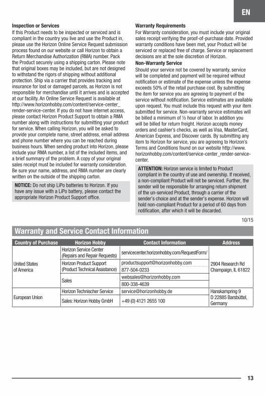
Inspection or ServicesIf this Product needs to be inspected or serviced and is compliant in the country you live and use the Product in, please use the Horizon Online Service Request submission process found on our website or call Horizon to obtain a Return Merchandise Authorization (RMA) number. Pack the Product securely using a shipping carton. Please note that original boxes may be included, but are not designed to withstand the rigors of shipping without additional protection. Ship via a carrier that provides tracking and insurance for lost or damaged parcels, as Horizon is not responsible for merchandise until it arrives and is accepted at our facility. An Online Service Request is available at http://www.horizonhobby.com/content/service-center_render-service-center. If you do not have internet access, please contact Horizon Product Support to obtain a RMA number along with instructions for submitting your product for service. When calling Horizon, you will be asked to provide your complete name, street address, email address and phone number where you can be reached during business hours. When sending product into Horizon, please include your RMA number, a list of the included items, and a brief summary of the problem. A copy of your original sales receipt must be included for warranty consideration. Be sure your name, address, and RMA number are clearly written on the outside of the shipping carton.
NOTICE: Do not ship LiPo batteries to Horizon. If you have any issue with a LiPo battery, please contact the appropriate Horizon Product Support office.
Warranty Requirements For Warranty consideration, you must include your original sales receipt verifying the proof-of-purchase date. Provided warranty conditions have been met, your Product will be serviced or replaced free of charge. Service or replacement decisions are at the sole discretion of Horizon.Non-Warranty ServiceShould your service not be covered by warranty, service will be completed and payment will be required without notification or estimate of the expense unless the expense exceeds 50% of the retail purchase cost. By submitting the item for service you are agreeing to payment of the service without notification. Service estimates are available upon request. You must include this request with your item submitted for service. Non-warranty service estimates will be billed a minimum of ½ hour of labor. In addition you will be billed for return freight. Horizon accepts money orders and cashier’s checks, as well as Visa, MasterCard, American Express, and Discover cards. By submitting any item to Horizon for service, you are agreeing to Horizon’s Terms and Conditions found on our website http://www.horizonhobby.com/content/service-center_render-service-center.
ATTENTION: Horizon service is limited to Product compliant in the country of use and ownership. If received, a non-compliant Product will not be serviced. Further, the sender will be responsible for arranging return shipment of the un-serviced Product, through a carrier of the sender’s choice and at the sender’s expense. Horizon will hold non-compliant Product for a period of 60 days from notification, after which it will be discarded.
10/15
Warranty and Service Contact InformationCountry of Purchase Horizon Hobby Contact Information Address
United States of America
Horizon Service Center (Repairs and Repair Requests) servicecenter.horizonhobby.com/RequestForm/
2904 Research Rd Champaign, IL 61822
Horizon Product Support (Product Technical Assistance)
European UnionHorizon Technischer Service [email protected] Hanskampring 9
D 22885 Barsbüttel, GermanySales: Horizon Hobby GmbH +49 (0) 4121 2655 100
EN
UMX Radian14
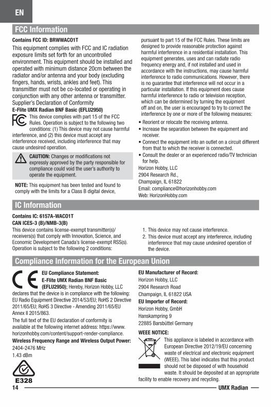
Compliance Information for the European Union
IC Information
FCC Information
Contains IC: 6157A-WACO1TCAN ICES-3 (B)/NMB-3(B) This device contains license-exempt transmitter(s)/receivers(s) that comply with Innovation, Science, and Economic Development Canada’s license-exempt RSS(s). Operation is subject to the following 2 conditions:
1. This device may not cause interference.2. This device must accept any interference, including
interference that may cause undesired operation of the device.
Contains FCC ID: BRWWACO1T
This equipment complies with FCC and IC radiation exposure limits set forth for an uncontrolled environment. This equipment should be installed and operated with minimum distance 20cm between the radiator and/or antenna and your body (excluding fingers, hands, wrists, ankles and feet). This transmitter must not be co-located or operating in conjunction with any other antenna or transmitter. Supplier’s Declaration of ConformityE-Flite UMX Radian BNF Basic (EFLU2950)
This device complies with part 15 of the FCC Rules. Operation is subject to the following two conditions: (1) This device may not cause harmful
interference, and (2) this device must accept any interference received, including interference that may cause undesired operation.
CAUTION: Changes or modifications not expressly approved by the party responsible for compliance could void the user’s authority to operate the equipment.
NOTE: This equipment has been tested and found to comply with the limits for a Class B digital device,
pursuant to part 15 of the FCC Rules. These limits are designed to provide reasonable protection against harmful interference in a residential installation. This equipment generates, uses and can radiate radio frequency energy and, if not installed and used in accordance with the instructions, may cause harmful interference to radio communications. However, there is no guarantee that interference will not occur in a particular installation. If this equipment does cause harmful interference to radio or television reception, which can be determined by turning the equipment off and on, the user is encouraged to try to correct the interference by one or more of the following measures:
• Reorient or relocate the receiving antenna.• Increase the separation between the equipment and
receiver.• Connect the equipment into an outlet on a circuit different
from that to which the receiver is connected.• Consult the dealer or an experienced radio/TV technician
for help.Horizon Hobby, LLC 2904 Research Rd.,Champaign, IL 61822Email: [email protected]: HorizonHobby.com
EU Compliance Statement:E-Flite UMX Radian BNF Basic (EFLU2950); Hereby, Horizon Hobby, LLC
declares that the device is in compliance with the following: EU Radio Equipment Directive 2014/53/EU; RoHS 2 Directive 2011/65/EU; RoHS 3 Directive - Amending 2011/65/EU Annex II 2015/863.The full text of the EU declaration of conformity is available at the following internet address: https://www.horizonhobby.com/content/support-render-compliance.Wireless Frequency Range and Wireless Output Power:2404-2476 MHz1.43 dBm
EU Manufacturer of Record:Horizon Hobby, LLC2904 Research RoadChampaign, IL 61822 USAEU Importer of Record: Horizon Hobby, GmbHHanskampring 922885 Barsbüttel Germany
WEEE NOTICE:This appliance is labeled in accordance with European Directive 2012/19/EU concerning waste of electrical and electronic equipment (WEEE). This label indicates that this product should not be disposed of with household waste. It should be deposited at an appropriate
facility to enable recovery and recycling.

© 2021 Horizon Hobby, LLC.E-flite, UMX, Radian, Bind-N-Fly, BNF, the Bind-N-Fly logo, SAFE, the SAFE logo, AS3X, ModelMatch, and the Horizon Hobby logo are
trademarks or registered trademarks of Horizon Hobby, LLC. The Spektrum trademark is used with permission of Bachmann Industries, Inc. US 9,056,667. US 9,753,457. US 10,078,329. US 9,930,567. US 10,419,970. US 10,849,013.
https://www.horizonhobby.comCreated 04/21 67416 EFLU2950