
UMTS Radio Access Techniques for IMT-Advanced · HSUPA: Enhanced uplink • Support for packet-data...
41
UMTS Radio Access Techniques for IMT-Advanced M. Sawahashi † , Y. Kishiyama †† , and H. Taoka †† † Musashi Institute of Technology †† Radio Access Development Department, NTT DoCoMo, Inc. February 6, 2008 High-Speed Packet Access Based on W-CDMA: HSDPA and HSUPA 3G Long-Term Evolution: Evolved UTRA and UTRAN Broadband Packet Radio Access for IMT-Advanced MIMO Experiments in Broadband Packet Radio Access Wireless Signal Processing & Networking Workshop at Tohoku University
Transcript of UMTS Radio Access Techniques for IMT-Advanced · HSUPA: Enhanced uplink • Support for packet-data...

UMTS Radio Access Techniques for IMT-Advanced
UMTS Radio Access Techniques for IMT-Advanced
M. Sawahashi†, Y. Kishiyama††, and H. Taoka††
†Musashi Institute of Technology††Radio Access Development Department,
NTT DoCoMo, Inc.February 6, 2008
M. Sawahashi†, Y. Kishiyama††, and H. Taoka††
†Musashi Institute of Technology††Radio Access Development Department,
NTT DoCoMo, Inc.February 6, 2008
High-Speed Packet Access Based on W-CDMA:HSDPA and HSUPA
3G Long-Term Evolution: Evolved UTRA and UTRAN Broadband Packet Radio Access for IMT-AdvancedMIMO Experiments in Broadband Packet Radio Access
Wireless Signal Processing & Networking Workshop at Tohoku University

2
February 6, 2008NTT DoCoMo Proprietary
High-Speed Packet Access Based on W-CDMA:HSDPA and HSUPA
High-Speed Packet Access Based on W-CDMA:HSDPA and HSUPA

3
February 6, 2008NTT DoCoMo Proprietary
Continuous Connectivity• Improved gaming support• Shortened setup delays
R99W-CDMA
R4 R5HSDPA
HSDPA: Enhanced downlink
• Support for packet-data service
• Shortened delay• High data rate (peak
data rate of 14.4 Mbps)• High frequency
efficiency
R6Enhanced UplinkMBMS
MBMS (Multimedia Broadcast Multicast Service)
• Efficiently achieves point-to- multipoint service
• Broadcast service such as mobile TV
HSDPA-MIMO• Multi-stream downlink• Increase in peak data
rate
R7MIMOConCon
HSUPA: Enhanced uplink• Support for packet-data
service• Shortened delay• High data rate (peak data
rate of 5.76 Mbps)• High frequency efficiency
Evolution of W-CDMA in 3GPP

4
February 6, 2008NTT DoCoMo Proprietary
Outline of HSDPA
Specification• Most specifications on HSDPA were completed as of Release 5• Specifications were finalized as of Release 6
Basic views on designing HSDPA air interface• Use functions of W-CDMA air interface specified as Release 99/4
smooth migration from R99 W-CDMA• Minimize increase in complexity
Development and implementation with low costLow power consuming UE
Objectives of HSDPA• High peak data rate up to 14 Mbps• High cell throughput (aggregated throughput per cell) and user
throughput • Focus on streaming (video streaming), interactive (gaming, E-mail,
FTP (File Transfer Protocol) download,...), background services Do not support conversation

5
February 6, 2008NTT DoCoMo ProprietaryHigh-Speed Downlink Shared Channel (HS-DSCH)
• Achieves efficient radio resource usage using shared channel among UEs (sets of user equipment)
• Enhancement of Downlink Shared Channel (DSCH) HS-DSCH• Introduction of short 2-msec transmission time interval (TTI)
Scheduling• Fast channel-dependent scheduling at Node B according to channel
conditions of each UE• Node B scheduler also considers QoS requirement of each UE
Adaptive rate control (AMC: Adaptive Modulation and Coding)• Achieve adaptive rate control according to instantaneous channel
conditions of each UE• Achieve adaptive rate control by changing modulation scheme and
channel coding rate (transport block size)Hybrid ARQ
• Hybrid ARQ with soft-combining with short round trip time• Use incremental redundancy with adaptive and asynchronous
operations in Stop & Wait (S&W) protocol
Key Techniques in HSDPA

6
February 6, 2008NTT DoCoMo Proprietary
Outline of HSUPA
Specification• Specifications on HSUPA were finalized as of Release 6
Basic views on designing HSUPA air interface• Use functions of W-CDMA air interface specified as Release 99/4• Support urban, suburban, and rural regions, from-low-to-high
mobility environments (optimize air interface under low mobility)• Large performance enhancement with minimum increase in
complexity of network and UE implementationObjectives of HSUPA
• Increase coverage area• Increase user throughput and cell throughput• Shorten delay (connection delay and transmission delay)• Focus on streaming (video streaming), interactive (gaming, E-mail,
FTP (File Transfer Protocol) upload,...), and background services

7
February 6, 2008NTT DoCoMo Proprietary
Enhancement of DPCH (Dedicated Physical Channel)E-DCH (Enhanced Dedicated Channel)
• Add short transmission time interval (TTI) of 2-msec • Introduce Spreading Factor (SF) of 2 to provide lower PAPR (3.84-
Mbps (raw data rate) is provided by 2 x SF of 2)• Use transmission power control and soft-handover similar to W-
CDMA caseScheduling
• Permit scheduled UE with data to use as high a data rate as possible without providing excessive interference to other UEs
• Grant based scheduling: Node B scheduler sends scheduling grant to assign maximum allowed transmission power for E-DCH to maintain the interference level at target valueHybrid ARQ
• Hybrid ARQ with soft-combining with short round trip time• Use incremental redundancy with synchronous and non-adaptive
operations
Key Techniques in HSUPA

8
February 6, 2008NTT DoCoMo Proprietary
3G Long-Term Evolution:Evolved UTRA and UTRAN (Super 3G)
3G Long-Term Evolution:Evolved UTRA and UTRAN (Super 3G)

9
February 6, 2008NTT DoCoMo Proprietary
Mid-term 3G RAN evolution based on W-CDMA: • HSDPA (High-Speed Downlink Packet Access)• HSUPA (High-Speed Uplink Packet Access)• MBMS (Multimedia Broadcast Multicast Service), etc.
Evolved UTRA and UTRAN (Super 3G)• Super 3G system will provide support for full IP
capabilities • Smooth introduction of IMT-Advanced (4G) system
Now3G long-term evolution
3G 3G 3G4GSuper 3G Super 3G
4G (IMT- Advanced)
Super 3G
UTRA: UMTS Terrestrial Radio Access
Migration to Radio Access Network for IMT-Advanced (4G)

10
February 6, 2008NTT DoCoMo Proprietary
10
Evolved UTRA and UTRAN represent long-term evolution (LTE) of technology to maintain continuous growth in mobile communications industry
• Competitive technology even in 4G (IMT-Advanced) era • RAN evolution to enable smooth migration to 4G (IMT-Advanced)
1980s 1990s 2000s 2010s 2020s1G
2G
4G (IMT-Advance3G
LaunchLaunch Long-termevolutionLong-termevolution
Commercial deployment: Accomplished successfully
Specifications and system development: Ongoing
Evolved UTRA and UTRANEvolved UTRA and UTRAN
Mid-termevolutionMid-termevolution
Evolved UTRA and UTRAN

11
February 6, 2008NTT DoCoMo Proprietary
Standardization of E-UTRA and UTRAN in 3GPP
Study Item (SI) investigation• SI investigation started in RAN in December 2004• Requirements were specified as TR25.913 in June 2005• Physical layer issues addressed by WG 1 (Working group 1)
were specified as TR25.814 in September 2006
Work Item (WI) investigation• WI investigation started from June 2006• Major WI specifications in WG1 were completed by
September 2007• WI specifications were completed as Release 8 in December
2007, but minor changes in specifications are ongoing

12
February 6, 2008NTT DoCoMo Proprietary
Requirements for Evolved UTRA and UTRAN
Spectrum• Support of scalable bandwidths, i.e., 1.4, 3, 5, 10, 15, and 20
MHz Packet-switching (PS) mode only
• VoIP capability in PS domainLatency
• Short C-plane latency (transition time)- Idle to active: Less than 100 msec- Dormant to active: Less than 50 msec
• U-plane latency- Latency in RAN is less than 5 msec one way
Peak data rate• DL: 100 Mbps, UL: 50 Mbps
User throughput (relative to Rel. 6 HSDPA, HSUPA) • Cell edge user throughput: 2 - 3 times (DL), 2 - 3 times (UL)• Average user throughput: 3 - 4 times (DL), 2 - 3 times (UL)
Spectrum efficiency (relative to Rel. 6 HSDPA, HSUPA) • 3 - 4 times (DL), 2 - 3 times (UL)

13
February 6, 2008NTT DoCoMo Proprietary
Short sub-frame lengthAdopted 1-msec sub-frame length to achieve short round trip delay (RTD)
Common frame structure between FDD and TDDInserted cyclic prefix (CP) at each FFT block to avoid inter-block interference in both DL and ULDefined sub-frame with long CP to provide MBMS (Multimedia Broadcast Multicast Service) with single-frequency network (SFN) in DL
Frame Structure in Evolved UTRA
Slot 1 Slot 2 Slot 3 Slot 4 Slot 19 Slot 20
Radio frame = 10 ms1 sub-frame = 2 slot = 1 ms transmission time interval (TTI)1 slot = 0.5 ms
Symbol 1 Symbol 2 Symbol 7Effective dataCP
Copy
14
February 6, 2008NTT DoCoMo Proprietary
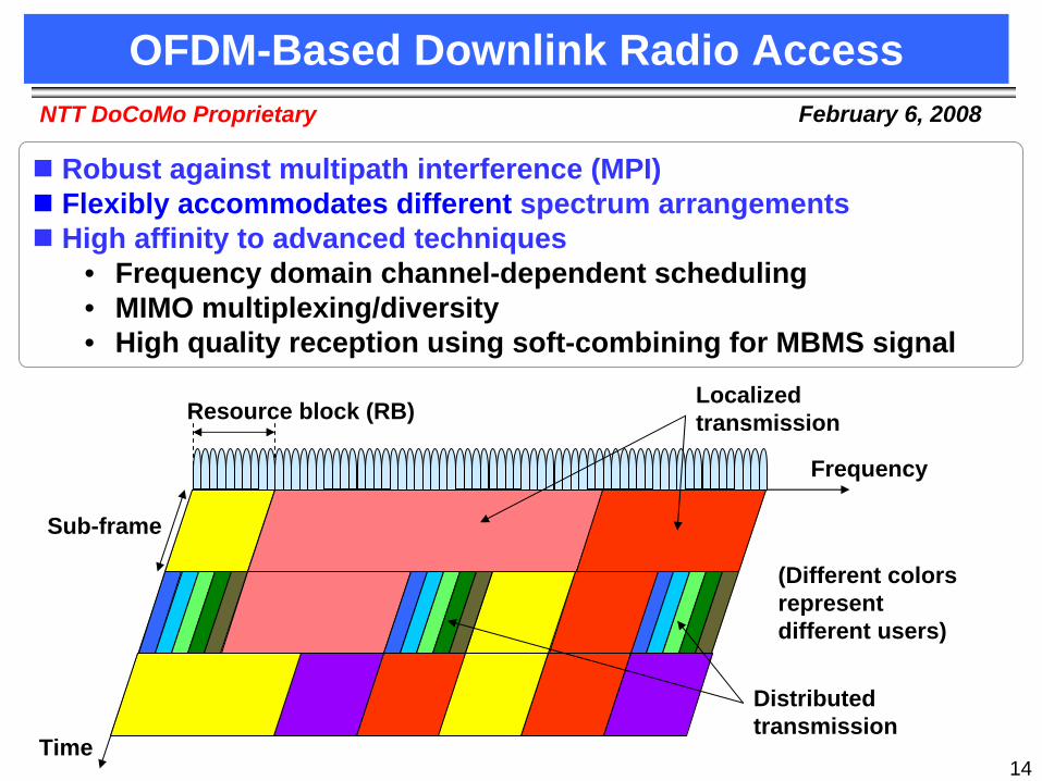
OFDM-Based Downlink Radio Access
Resource block (RB)
Frequency
Time
Sub-frame
Localized transmission
Distributed transmission
(Different colors represent different users)
Robust against multipath interference (MPI)Flexibly accommodates different spectrum arrangementsHigh affinity to advanced techniques
• Frequency domain channel-dependent scheduling• MIMO multiplexing/diversity• High quality reception using soft-combining for MBMS signal

15
February 6, 2008NTT DoCoMo Proprietary
Coded datasymbol
Transmitsignal
DFT
IFFT
Sub-
carr
ier
map
ping
DFT-Spread OFDM
Single-Carrier-Based Uplink Radio Access
Resource unitFreq.
Time
Sub- frame
Frequency hopping
Frequency scheduling
Contiguous resource units are assigned to UE to maintain the single-carrier property
Add
ition
of C
P
Single-carrier based FDMA access in uplink • Low PAPR (Peak-to-average power ratio) achieves wide area
coverage using limited transmission power• Localized and/or distributed FDMA establishes intra-cell
orthogonality among simultaneous transmitting users in frequency domain
• Employs frequency domain equalizer with cyclic prefix to suppress MPI

16
February 6, 2008NTT DoCoMo Proprietary
W-CDMADownlink Partially orthogonal
• Achieves orthogonality within a cell using Walsh-Hadamard OVSF sequences
• However, multipath interference impairs performance (note that mandatory function is coherent Rake receiver)Uplink Non-orthogonal
• Non-orthogonal transmission using user-specific scrambled sequence at asynchronous-timing receptionEvolved UTRADownlink Orthogonal
• Achieves orthogonality within a cell in frequency domain for the delayed paths within cyclic prefix durationUplink Orthogonal
• Achieves orthogonality within a cell in frequency and/or code domain in SC-FDMA associated with frequency-domain equalizer
Radio Access Comparisons Between W-CDMA and E-UTRA

17
February 6, 2008NTT DoCoMo Proprietary
Inter-Node B (cell) synchronization• Air interface supports inter-cell asynchronous mode as baseline• However, utilize merits of synchronized operation for MBMS with SFN
and inter-cell interference coordination, etc.Cell search: Process to search for the best cell with the minimum path loss
• DoCoMo proposed SCH (Synchronization Channel) and Primary BCH (Broadcast Channel) structures appropriate for fast cell search in scalable transmission bandwidth from 1.4 to 20 MHz
Reference signal (RS)• Used for channel estimation and channel-quality measurement• Orthogonal RSs between transmitter antennas in MIMO
Data modulation• DL: QPSK, 16QAM, 64QAM• UL: QPSK, 16QAM, 64QAM (Optional)
Channel coding• Turbo code (Data channel) and convolutional code (Control signals)
Hybrid ARQ with packet combining• Incremental redundancy (IR)
Radio Access Features in Evolved UTRA

18
February 6, 2008NTT DoCoMo Proprietary
Link Adaptation
Use 1
User 2
Low transmission power for user experiencing good conditions
High transmission power for user experiencing poor conditions
TPC (Transmission power control)
Applied to constant-rate service such as real-time traffic and control channelSatisfies the constant required received SNR for channel variationAffects other-cell interference
User 1
User 2
I
Q
64QAM(6 bit/symbol)
Q
QPSK(2 bit/symbol)
AMC (Adaptive Modulation and Coding)
Applied particularly to variable-rate services such as non-real-time trafficRate adaptation according to channel conditionsAchieves higher capacity, i.e., cell throughput, than TPC
Low data rate transmission
High data rate transmission

19
February 6, 2008NTT DoCoMo Proprietary
BS #1
BS #2
BS #3
User #2
User #1
Soft-combiningTime
From BS #1From BS #2
Cyclic prefix length
From BS #3
Rec
eive
d po
wer
MBMS Using Soft-Combining in SFN
Efficient MBMS with soft-combining in single frequency network (SFN): Received paths from multiple cell sites within a cyclic prefix are combined without yielding mutual interference

20
February 6, 2008NTT DoCoMo Proprietary
Inter-cell Interference Mitigation
• One-cell frequency reuse for user near cell site
• Multi-cell frequency reuse for a UE near cell edge using FDMA to reduce other-cell interference
Optimize balance between cell throughput and user throughput at cell edge
Inter-cell Interference Mitigation• Randomization using cell-specific scrambling code associated
with channel coding and repetition to achieve one-cell frequency reuse
• Interference cancellation: Interference canceller, MMSE receiver etc.
• Interference coordination: Autonomous scheduling to establish fractional frequency reuse (fast inter-Node B communication should be avoided)Inter-cell interference coordinationIntroduction of partial multi-cell frequency reuse near cell edge

21
February 6, 2008NTT DoCoMo ProprietaryMIMO multiplexing (MIMO SDM)
• Baseline is 2-by-2 MIMO in downlink and 1-by-2 SIMO in uplink• Single-user MIMO and multiuser MIMO (single-user MIMO in uplink is FFS)• Major techniques applied
• Pre-coding • Single/double coded streams (code words)• Rank adaptation (selection of MIMO mode) based on channel
measurementMIMO diversity (transmit diversity)Supports transmit diversity, which is suitable for each physical channel property
• DL: PVS (Precoding vector switching) for SCH, SFBC (Space Frequency Block Code) based scheme for control channels, and CDD (Cyclic Delay Diversity) for MBMS
• UL: TSTD (Time-Switched Transmit Diversity) for RACH and ASTD (Antenna Selection Transmit Diversity) for data channel (Option)
Adaptive beam-formingAdaptive beam-forming is effective in increasing coverage area particularly for large cells
MIMO Channel Techniques
22
February 6, 2008NTT DoCoMo Proprietary
Broadband Packet Radio Access for IMT-Advanced
Broadband Packet Radio Access for IMT-Advanced

23
February 6, 2008NTT DoCoMo Proprietary
Requirements for IMT-Advanced
4G systems are real broadband wireless networksPacket-based radio access networks (RANs) provide equal or greater peak data rates than those for wired networks while maintaining equivalent QoS Technical requirements
• Reduced network cost (cost per bit)Higher capacity (frequency efficiency) Ex. frequency efficiency of 4 times that of Evolved UTRAWider area coverage Equal or wider than that in 3GSimpler deployment and network operation
• Better service provisioningHigher user data rate Ex. peak data rate of greater than 1 Gbps with wider bandwidthVery low latency (connection and transmission delays)Efficient unified support of all traffic types with precise QoS control
• Complement to 3G (legacy) systemsFlexible spectrum usage Ex. scalable transmission bandwidth up to 100 MHzHandover with 3G system and backward compatibility with existing 3G and legacy systems

24
February 6, 2008NTT DoCoMo Proprietary
Migration to IMT-Advanced
W-CDMA, HSDPA/HSUPA• 3GPP standardization: from 1998, Commercial service launch: W-
CDMA 2001, HSDPA 2006• Peak data rate wide area: 1 Mbps, local area: 10 Mbps• Mobility focus
Long-term 3G evolution (Evolved UTRA and UTRAN)• 3GPP standardization: from 2004, Commercial service launch:
targeting 2009 – 2010• Peak data rate wide area: 10 Mbps, local area: 100 Mbps• Supports only packet domain• Further improvement in throughput particularly at cell edge
IMT-Advanced (4G) • Peak data rate wide area: 100 Mbps, local area: 1 Gbps• Extend 3G LTE capability and performance• New radio interfaces

25
February 6, 2008NTT DoCoMo Proprietary
Duplex Scheme
25
Should support both paired and unpaired bands to achieve global air interface
TDD• Merit: Pair-band is unnecessary• Demerit: Increase in RTD (round trip delay) and decrease in coverage
area
FDD• Merit: Short RTD and provides wide area coverage• Demerit: Pair-band is necessary Restrictions on pair-band
assignment can be relaxed using asymmetric spectrum assignment according to the traffic demand between DL and UL
Compared to TDD, FDD is more promising based on system requirements such as a short delay and wide area coverage, although TDD is more advantageous from the spectrum allocation viewpoint.
・・ ・・・
Slots for UL Slots for DL
Retransmission using the next DL slot assignment duration Increase in RTD
Repetition is possible only over UL slot assignment duration Limits coverage

26
February 6, 2008NTT DoCoMo Proprietary
26
(1) Multi-accessSupports Evolved UTRA and achieves backward compatibility with 3G systemsAccommodates frequency spectrum with various bandwidthsscalable transmission bandwidthsEmploys adaptive multi-access scheme according to deployment environment, QoS requirements, etc.
(2) Intra- and inter-cell site (BS) orthogonalityIntra-cell site orthogonality: Orthogonal multi-access in frequency/code domains within the same cell site similar to E-UTRAInter-cell site (quasi) orthogonality: Inter-cell site fast radio resource management (i.e., Interference management)
(3) Adaptive multi-antenna transmission/receptionMode (rank) selection adapts according to deployment environmentand QoS using the same antenna configuration: MIMO multiplexing,MIMO diversity, pre-coding, and beam forming
(4) Enhanced site diversity to extend area coverageRemote-BS using optical fiber, relay BS using radio, etc.
Key Radio Access Techniques for IMT-Advanced

27
February 6, 2008NTT DoCoMo ProprietaryMulti-Carrier (MC)/Single-Carrier (SC) hybrid (Adaptive multi-access control)
• Universal switching of MC/SC based access using frequency domain multiplexing/de-multiplexing
• Optimizations of PAPR (coverage) and achievable peak data rate according to inter-site distance, cell structure, and QoS requirements
Adaptive Multi-access Scheme
DFT
Sub- carrier
mappingIFFT
CPinsertionCoded data
symbols
[Ref] R. Dinis et al., “A Multiple Access Scheme for the Uplink of Broadband Wireless Access,” IEEE Globecom, Dec. 2004.
S/P
Switch
SC generation
MC generation
Pulse- shaping
filter

28
February 6, 2008NTT DoCoMo Proprietary
28
Wide area Local area(Heavy traffic in small area)
Adaptive Radio Access Concept
Control of multi-access schemes adapts according to deployment environment and required QoSCell distance, i.e., wide area or local area
• For wide area coverage, low PAPR feature is necessarySC based multiple access is appropriate
QoS on peak data rate and packet error rate (PER)• To provide high data rate, robustness against MPI is necessary
MC based multiple access is appropriate

29
February 6, 2008NTT DoCoMo Proprietary
W-CDMA E-UTRA IMT-AdvancedIntra-cell site
DL (Partially) orthogonal
Orthogonal Orthogonal
UL Non-orthogonal Orthogonal OrthogonalInter-cell site
DL Non-orthogonal Non-orthogonal (Quasi)-orthogonalUL Non-orthogonal Non-orthogonal (Quasi)-orthogonal
Inter-cell Site Orthogonality
One-cell frequency reuse• Baseline is one-cell frequency reuse to achieve high system capacity
Intra-cell site (Intra-BS) orthogonality• Achieves intra-cell site orthogonal multi-access (multiplexing) in both links
as well as in E-UTRAInter-cell site orthogonality
• Although inter-cell interference coordination (ICIC) is adopted in E-UTRA, it only introduces fractional frequency reuse at cell edge, which is semi- statically controlled with slow control speed
• Thus, inter-cell site orthogonality will be established in IMT-Advanced to achieve high frequency efficiency and high data rate at cell edge

30
February 6, 2008NTT DoCoMo Proprietary
Centralized inter-cell interference control
Autonomous inter-cell interference control
Adaptive Inter-cell Interference Management
Achieve inter-cell site orthogonality through adaptive inter-cell interference management
• Centralized inter-cell interference management among remote-BSs using optical fiber belonging to the same control BS achieves complete inter-cell site orthogonality
• Autonomous inter-cell interference management among independent cell sites using control signals via backhaul and/or air
achieves inter-cell site quasi-orthogonality through slow adaptive control of partial multi-cell frequency reuse at the cell edge
31
February 6, 2008NTT DoCoMo Proprietary
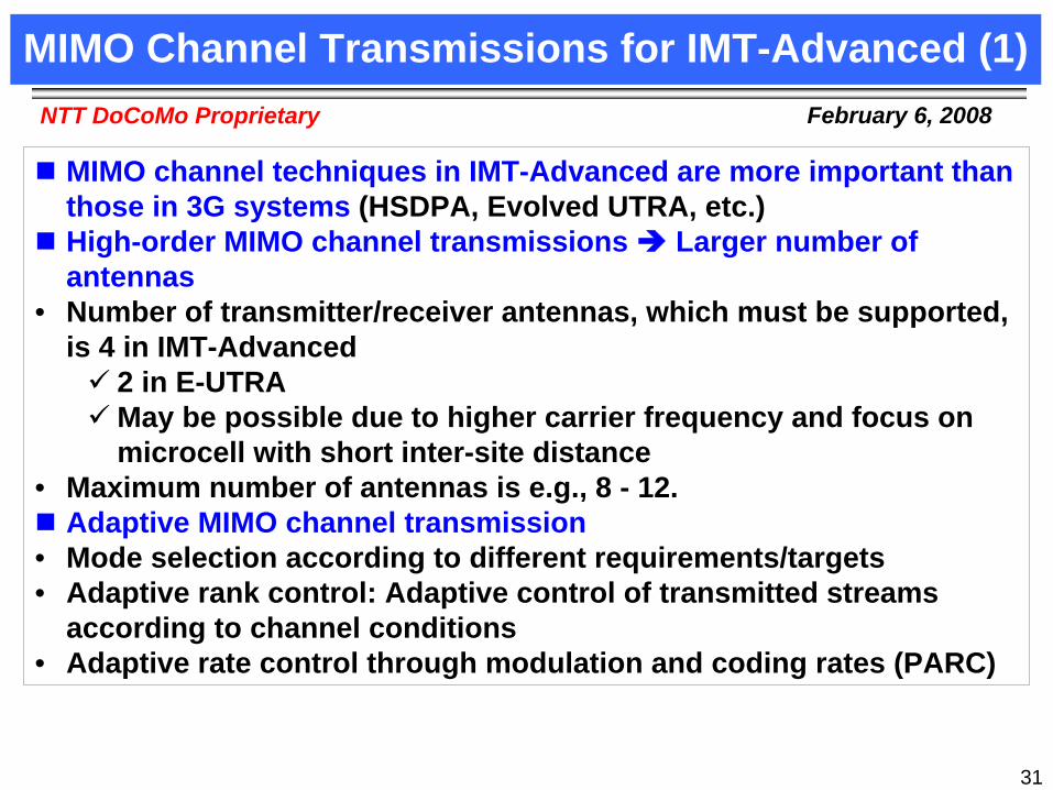
MIMO Channel Transmissions for IMT-Advanced (1)
MIMO channel techniques in IMT-Advanced are more important than those in 3G systems (HSDPA, Evolved UTRA, etc.)High-order MIMO channel transmissions Larger number of antennas
• Number of transmitter/receiver antennas, which must be supported, is 4 in IMT-Advanced
2 in E-UTRAMay be possible due to higher carrier frequency and focus on microcell with short inter-site distance
• Maximum number of antennas is e.g., 8 - 12.Adaptive MIMO channel transmission
• Mode selection according to different requirements/targets• Adaptive rank control: Adaptive control of transmitted streams
according to channel conditions• Adaptive rate control through modulation and coding rates (PARC)

32
February 6, 2008NTT DoCoMo Proprietary
MIMO multiplexing (SDM, multi-layer transmission) • Increase in the peak data rate, i.e., frequency efficiency beyond 10
bit/second/Hz• High capacity through SDM among multiple UEs
MIMO diversity (transmit diversity)• Improvement in received quality and coverage area • Key question: Achievable diversity gain is offset by increasing
overhead of orthogonal reference signals according to increasing number of transmitter antennas. What is the optimum number of transmitter antennas?Adaptive beam forming
• Increase in coverage and achievable data rate at cell edge• High capacity through SDM among UEs• Key problem: Increase in coverage of common/shared control
channels.
MIMO Channel Transmissions for IMT-Advanced (2)

33
February 6, 2008NTT DoCoMo Proprietary
MIMO Experiments in Broadband Packet Radio Access
for IMT-Advanced
MIMO Experiments in Broadband Packet Radio Access
for IMT-Advanced

34
February 6, 2008NTT DoCoMo Proprietary
Target Peak Data Rates for IMT-Advanced
Target peak data rate is one of the most important requirements in radio access systems
Targets data rates specified in standardization or forum ITU-R Recommendation M.1645Peak data rate of 100-Mbps in new mobile access under high mobilityPeak data rate of 1-Gbps in new nomadic/local area wireless access under low mobility
IST-2003-507581 in WINNERD7.1 v1.0 System Requirements (2004.07.16)
Peak spectral efficiency in connected sites of 10 b/s/Hz/site in wide area deployments for heavy traffic loadsPeak spectral efficiency in isolated (non-contiguous) sites of 25
b/s/Hz/site

35
February 6, 2008NTT DoCoMo Proprietary
Experimental demonstrations of target peak data rates for IMT-Advanced
May 2003: Achieved 100 Mbps transmission in field experiments at the speed of 30 km/h in downtown Yokosuka
• Peak data rate of 135 (300) Mbps using 16QAM (64QAM) modulation and Turbo code with R = 1/2 (3/4)
Aug. 2004: Achieved 1 Gbps transmission with 4-by-4 MIMO SDM in laboratory experiments using fading simulators (10 bit/second/Hz)May 2005: Achieved 1 Gbps transmission in field experiments at the speed of 30 km/h in downtown Yokosuka
• Peak data rata of 1.028 Gbps using 16QAM modulation and Turbo code with R = 8/9
Dec. 2005: Achieved 2.5 Gbps transmission with 6-by-6 MIMO SDM in field experiments at the speed of 10 - 30 km/h in YRP district (25 bit/second/Hz)
• Peak data rata of 2.556 Gbps using 64QAM modulation and Turbo code with R = 8/9
Series of Experimental Demonstrations for IMT-Advanced Radio Access by DoCoMo

36
February 6, 2008NTT DoCoMo Proprietary
5-Gbps Packet Transmission (Frequency efficiency of 50 bit/second/Hz)
5-Gbps Packet Transmission (Frequency efficiency of 50 bit/second/Hz)

37
February 6, 2008NTT DoCoMo Proprietary
Features of Experimental Configuration
(1) OFDM radio access with 100-MHz transmission bandwidth(2) Efficient modulation and channel coding scheme
• 64QAM modulation• Turbo code with coding rate of R = 8/9• Multiple codewords
(3) 12-by-12 MIMO multiplexing(4) MLD-based signal detection
• QRM-MLD[1] with ASESS[2] (adaptive selection surviving symbol replica candidates based on maximum reliability)
• LLR (log-likelihood ratio) generation appropriate for QRM- MLD
[1] K. J. Kim, et al., IEEE Trans. on Wireless Commun., vol. 4, no. 2, pp. 710 - 721, March, 2005.[2] K. Higuchi, et al., in Proc. IEEE Globecom’2004, Nov. 2004.
38
February 6, 2008NTT DoCoMo Proprietary
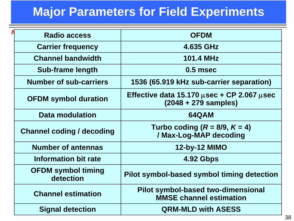
Major Parameters for Field Experiments
Radio access OFDMCarrier frequency 4.635 GHz
Channel bandwidth 101.4 MHzSub-frame length 0.5 msec
Number of sub-carriers 1536 (65.919 kHz sub-carrier separation)
OFDM symbol duration Effective data 15.170 μsec + CP 2.067 μsec (2048 + 279 samples)
Data modulation 64QAM
Channel coding / decoding Turbo coding (R = 8/9, K = 4) / Max-Log-MAP decoding
Number of antennas 12-by-12 MIMOInformation bit rate 4.92 Gbps
OFDM symbol timing detection Pilot symbol-based symbol timing detection
Channel estimation Pilot symbol-based two-dimensional MMSE channel estimation
Signal detection QRM-MLD with ASESS

39
February 6, 2008NTT DoCoMo Proprietary
0
1
2
3
4
5
24 25 26 27 28 29 30
Effect of Antenna Separation Between Receiver Antennas
When d is reduced from 40 cm to 10 cm, the loss in the required received SNR is only 0.5 dB.Achieved 4.9-Gbps throughput at average received SNR of approximately 28.5 (29) dB when d is 40 (10) cm.Loss in the required average received SNR compared to simulation is approximately 1 dB.
• 12-by-12 MIMO multiplexing• 64QAM, R = 8/9 (Max: 4.92 Gbps)• Antenna separation: D = 70 cm• Average speed: v = 10 km/h
Rx antenna separationd = 10 cm (1.5λ)d = 20 cm (3.1λ)d = 40 cm (6.2λ)
SimulationField experiments
Thro
ughp
ut (G
bps)
Average total received SNR per receiver antenna (dB)

40
February 6, 2008NTT DoCoMo Proprietary
0
1
2
3
4
5
24 25 26 27 28 29 30
Effect of Moving Speed of Mobile Station(Throughput Performance)
Even when v is 30 km/h, the loss in the required received SNR is only 1 dB.Achieved 4.9-Gbps throughput at average received SNR of approximately 29.5 dB when vis 30 km/h.
• 12-by-12 MIMO multiplexing• 64QAM, R = 8/9 (Max: 4.92 Gbps)• Antenna separation
Transmitter: D = 70 cmReceiver: d = 20 cm
SimulationField experiments
Thro
ughp
ut (G
bps)
Average total received SNR per receiver antenna (dB)
v = 10 km/hv = 20 km/hv = 30 km/h

41
February 6, 2008NTT DoCoMo Proprietary
Conclusion
Evolved UTRA and UTRAN, which adopts competitive technology even in 4G era, will achieve smooth migration to 4G systems
• WI specifications were completed last December
IMT-Advanced systems will be real broadband packet-based radio access networks (RANs) that provide equal or greater peak data rates than those for wired networks while maintaining equivalentQoS (delay and quality)
• Adaptive control of multi-access schemes and major radio parameters, intra- and inter-cell site interface management, higher-order MIMO schemes etc. are promising.
Field experiments demonstrated the feasibility of peak throughput of 5 Gbps, i.e., corresponding frequency efficiency of 50 bit/second/Hz, which is close to the ultimate frequency efficiency in cellular environments


