Universal Mobile Telecommunications System (UMTS); UMTS 22.05
Upload
haque-nawaz-lashariCategory
view
19download
3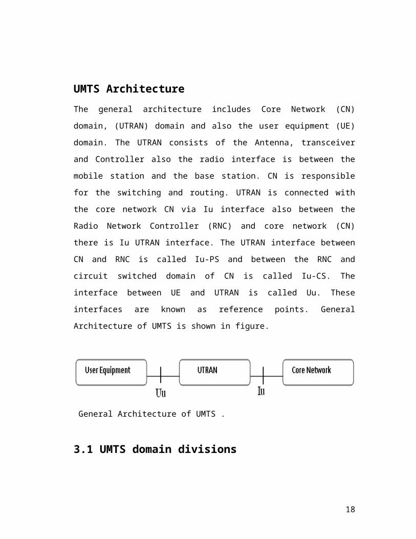
UMTS ArchitectureThe general architecture includes Core Network (CN) domain, (UTRAN) domain and
also the user equipment (UE) domain. The UTRAN consists of the Antenna,
transceiver and Controller also the radio interface is between the mobile station and
the base station. CN is responsible for the switching and routing. UTRAN is
connected with the core network CN via Iu interface also between the Radio Network
Controller (RNC) and core network (CN) there is Iu UTRAN interface. The UTRAN
interface between CN and RNC is called Iu-PS and between the RNC and circuit
switched domain of CN is called Iu-CS. The interface between UE and UTRAN is
called Uu. These interfaces are known as reference points. General Architecture of
UMTS is shown in figure.
General Architecture of UMTS .
3.1 UMTS domain divisionsThe architecture of the UMTS consists of two main domains divisions
The User Equipment Domain
The Infrastructure Domain
The domains are shown in the following figure.
18
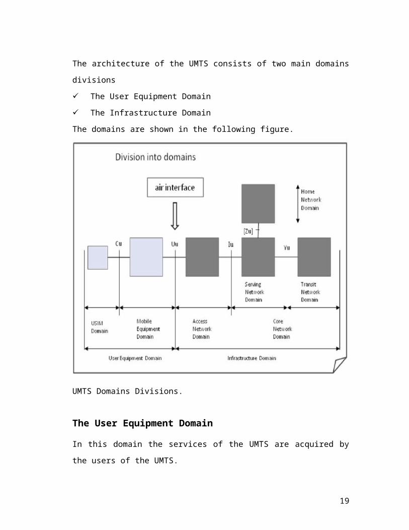
UMTS Domains Divisions.
The User Equipment Domain
In this domain the services of the UMTS are acquired by the users of the UMTS.
UMTS User Equipment.
19
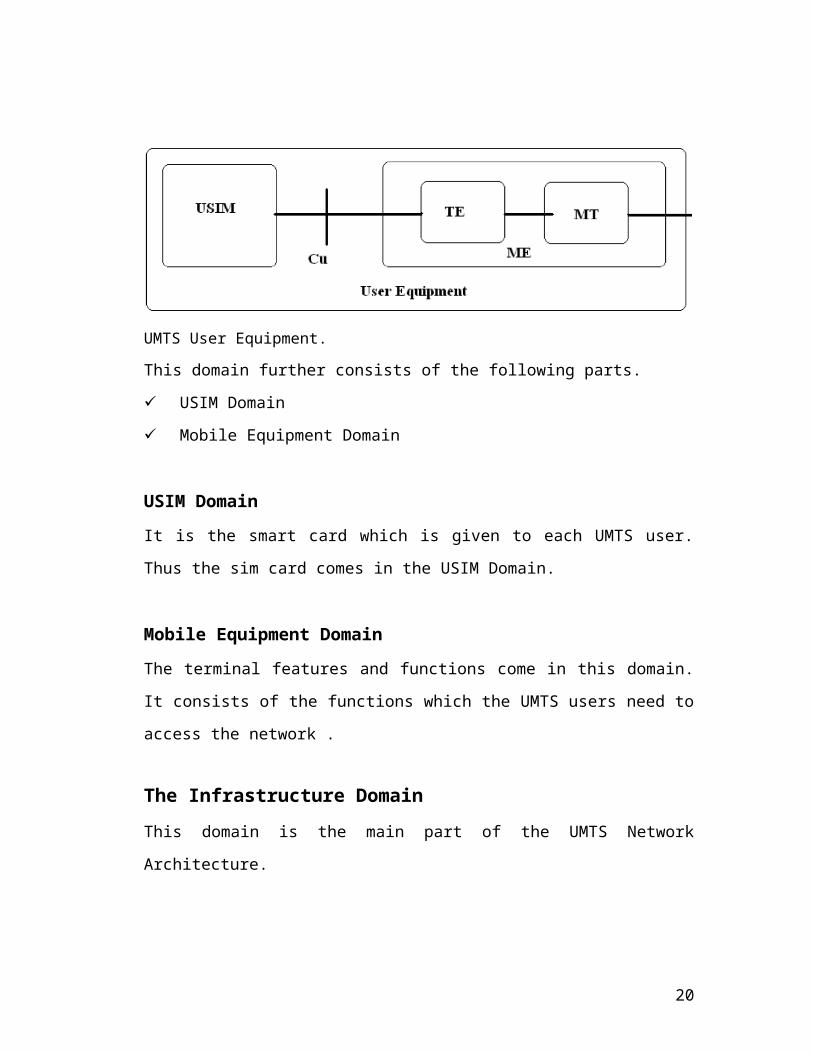
This domain further consists of the following parts.
USIM Domain
Mobile Equipment Domain
USIM Domain
It is the smart card which is given to each UMTS user. Thus the sim card comes in
the USIM Domain.
Mobile Equipment Domain
The terminal features and functions come in this domain. It consists of the functions
which the UMTS users need to access the network .
The Infrastructure DomainThis domain is the main part of the UMTS Network Architecture.
UMTS Network Architecture.
20
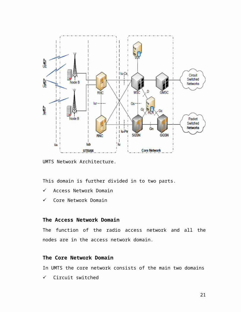
This domain is further divided in to two parts.
Access Network Domain
Core Network Domain
The Access Network Domain
The function of the radio access network and all the nodes are in the access network
domain.
The Core Network Domain
In UMTS the core network consists of the main two domains
Circuit switched
Packet switched
The Asynchronous Transfer Mode (ATM) Adaptation Layer Type 2 (AAL2) control
the circuit switched data where as the Adaptation Layer Type 5 (AAL5) will control
the packet switched data.
Circuit Switched Domain The elements of the circuit switched domain
connected to UTRAN via interface Iu-CS are the Mobile services Switching
Center (MSC), Visitor Location Register (VLR), Home Location Register
(HLR) and Gate way MSC.
Packet switched Domain The major elements of the packet switched domain
connected to UTRAN via interface Iu-PS are the serving GPRS Support Node
(SGSN) and Gateway GPRS Support Node (GGSN).Some of the network
elements are used by both the domains. These are EIR, HLR, VLR and AUC.
The Core Network Domain is further divided in to three sub domains which are
exactly alike in some cases.
Serving Network Domain
Transit Network Domain
Home Network Domain
21
Serving Network Domain
This sub domain consists of the features of the particular core network that at some
particular time the UMTS user’s uses.
Transit Network Domain
In the case that the serving network is not directly connected to home network the
data passes to the transit network. The transit network functions are present in the
transit network domain.
Home Network Domain
The features and the functions done in the user home network come in the home
network domain.
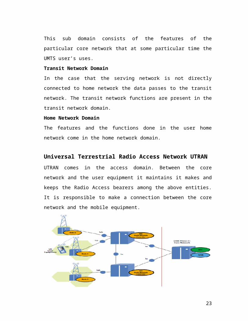
Universal Terrestrial Radio Access Network UTRANUTRAN comes in the access domain. Between the core network and the user
equipment it maintains it makes and keeps the Radio Access bearers among the above
entities. It is responsible to make a connection between the core network and the
mobile equipment.
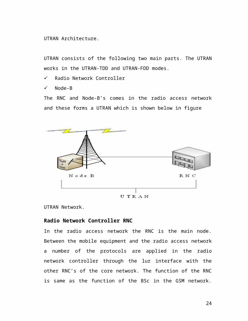
UTRAN Architecture.
UTRAN consists of the following two main parts. The UTRAN works in the
UTRAN-TDD and UTRAN-FDD modes.
22
Radio Network Controller
Node-B
The RNC and Node-B’s comes in the radio access network and these forms a
UTRAN which is shown below in figure
UTRAN Network.
Radio Network Controller RNC
In the radio access network the RNC is the main node. Between the mobile
equipment and the radio access network a number of the protocols are applied in the
radio network controller through the lur interface with the other RNC’s of the core
network. The function of the RNC is same as the function of the BSc in the GSM
network. The radio resource management is controlled in more than one Node-B by
the RNC. The following are tasks of the RNC.
Through the radio interface it performs all the data transmission tasks.
The radio resources are managed by this entity.
The connection and the releasement of the radio bearers.
The admission of the call control through the Call admission control.
The allocation of the code is also the duty of this entity.
The control of power.
Helps in handovers and the scheduling of the packet.
The relocation of the SRNS and the conversion of the protocol.
23
The data coming from other networks are ciphered in the RNC’s.
To enable the transformation of the various entities RNC can connect and
switch to ATM connection.
There are three types of RNC’s.
Serving RNC
Controlling RNC
Drift RNC
Serving RNC
This RNC serves the user equipment because the user equipment is connected to this
RNC. That is why this RNC is called as the serving RNC.
Controlling RNC
It works with reference to the Node – B.
Drift RNC
It works in the process of handover.
Node- B
Its functions are similar to the BTS in the GSM network. The Node-B’s are also
called as the radio network controller. The following are functions of the Node-B.
Many cells are managed by the Node-B.
The tasks which are attached to the radio interface is manage in the Node-B.
The data splitting and the combination is also the duty of this entity.
It helps in the process of handovers too.
It uses the mechanism for power control known as the inner loop power control.
Node – B is the base station, which gives the network coverage to the MT in a
terrestrial cell.
Node-B’s has three types which include the following.
UTRA-TDD Node B
UTRA-FDD Node B
Dual Node B
24
Components of the core networkThe following are the different parts of the core network which have different
functionalities
Mobile Switching Center (MSC)
It is the switching entity. It supports the circuit switched connection. It also supports
the mobility of the users. The current location of the user is known to the MSC. It
also works in authentication and the user data encryption
Visitor Location Register (VLR)
It is the data base and it stores the copy data from HLR. The VLR stores the dynamic
data. The VLR Update the information when users change its area.
Home Location Register (HLR)
It is also the database same as the VLR. All the data of the users are stored in this
database. Its main responsibility is the mobile user’s mobility.
Gateway Mobile Switching Center (GMSC)
The circuit switch network between the outside network and the core network is
provided by the GMSC.
Serving GPRS Support Node (SGSN)
The user’s current location is stored in SGSN. It performs the functionality of the
routing. Authentication and the copy of information of the user are stored in SGSN.
Gateway GPRS Support Node (GGSN)
The internet is connected to this node. It is the gate way to other packet networks.
Usually firewall is containing in this entity.
25
GPRS register
It is the data base that is part of HLR. The packet switch transmission information is
stored in this register.
All these entities of the UMTS access plane are shown in Figure.
UMTS Access plane Architecture.
UMTS InterfacesThe following are the different interfaces in the UMTS.
Iub
Iur
Uu
Iu
Iu-cs
Iu-ps
The following section gives a brief description of the above UMTS interfaces
26
Iub Interface
The RNC and the Node-B’s are connected through the Lub interface. There are many
functionalities of this interface which include the management of the information
system, the validation of the message on the user side, management of the traffic on
different channels like in control and the dedicated channel and timings and the
management of the link status.
Iur Interface
Two RNC’s are connected to the interface known as Lur interface. The functionalities
of this interface include management of the traffic in different channels like dedicated
and common transport channel and management of the SAAl connection.
Uu Interface
The RNC and the mobile equipment through the Node –B’s are connected to this
interface. The main functionalities of this interface include paging and the
management of the security, MAC/RLC reconfiguration and configuration and the
handling of priority and the selection of the TFC.
Iu Interface
The core network and the RNC’s are connected through the Iu interface. The main
functionalities of the Iu Interface include establishment of the radio access bearers, its
maintenance and the releasement is also the responsibility of this interface.
Iu-CS
The RNC’s connected to the circuit switched domain of the core network through this
interface.
Iu-PS
The RNC’s connected to the packet switched domain of the core network through this
interface. The following figure shows the different interfaces.
27
Different Interface of UMTS.
28