Uml training
67
-
Upload
somenath-mukhopadhyay -
Category
Software
-
view
1.044 -
download
0
Transcript of Uml training

UML Training
by
Somenath Mukhopadhyay

Part I – Use Case
Part II – Class Diagram
Part III – Sequence Diagram

Use Case Analysis

What is a Use Case
● A formal way of representing how a business system interacts with its environment
● Illustrates the activities that are performed by the users of the system
● A scenario-based technique in the UML
● A sequence of actions a system performs that yields a valuable result for a particular actor.
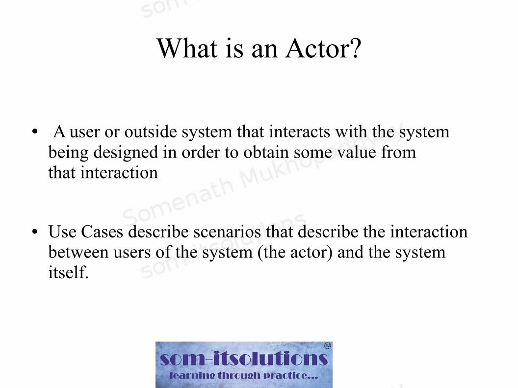
What is an Actor?
● A user or outside system that interacts with the system being designed in order to obtain some value from that interaction
● Use Cases describe scenarios that describe the interaction between users of the system (the actor) and the system itself.

● Use case diagrams describe what a system does from the standpoint of an external observer. The emphasis is on what a system does rather than how.
● Use case diagrams are closely connected to scenarios. A scenario is an example of what happens when someone interacts with the system.

Step 1 - Identify the actors
As we read the scenario, define those people or systems that are going to interact with the scenario.
A customer enters a restaurant and requests for a table. The receptionist finds an empty table and asks the customer to occupy it.

Questions for identifying People Actors
● Ask client and domain experts how system will be used
● Who will perform the obvious tasks? Secondary tasks of maintenance and administration? Interact with other systems?

Questions for identifying other Actors
● What other entity is interested in the scenario/system?
● What other entity will supply the scenario/system with this information, use this information, and remove this information?
● Does the system use an external resource?
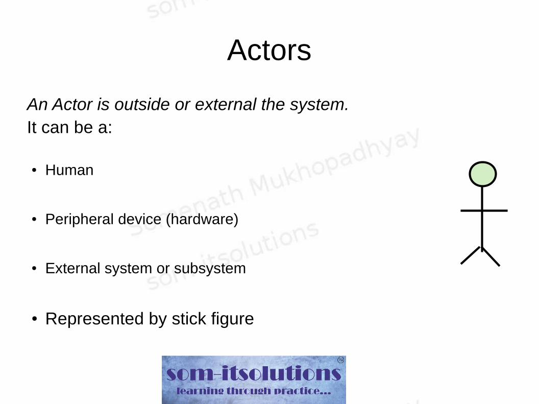
Actors
An Actor is outside or external the system.It can be a:
● Human
● Peripheral device (hardware)
● External system or subsystem
● Represented by stick figure

Step 2 – Recording the use case
For each actor, what interactions they require of the system – each is a use case
● What tasks does the actor want the system to perform
● What information must the actor provide to the system
● Are there events that the actor must tell system about
● Does actor need to be informed when something happens
● Does actor help initialize or shut down the system

Case Study – Restaurant System
Actor : Customer
● What tasks does the actor want the system to perform?
- Find an empty table to occupy, display the menu card, take the order & accept the payment
● What information must the actor provide to the system?
- How many guests are there with him, choice of his menu and how many plates for each of them
● Are there events that the actor must tell system about?
- Whether he wants to pay through credit card/check/cash
● Does actor need to be informed when something happens?
- If any menu chosen by the customer is not available he has to be informed
● Does actor help initialize or shut down the system
- no
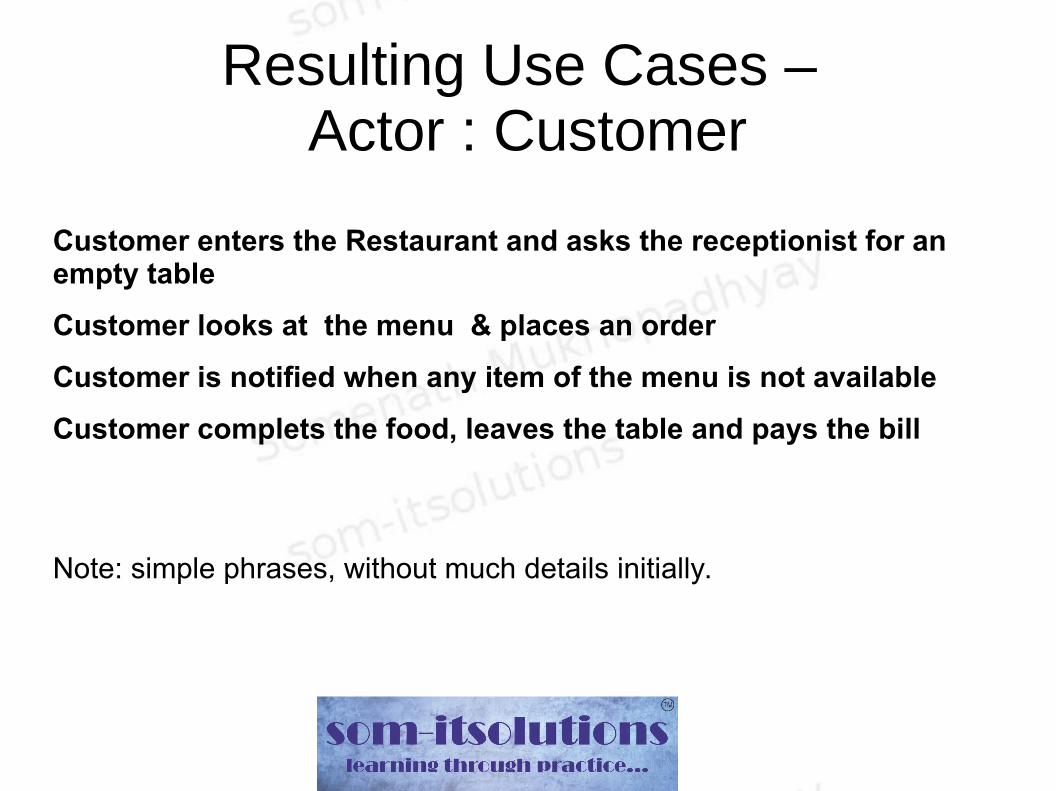
Resulting Use Cases – Actor : Customer
Customer enters the Restaurant and asks the receptionist for an empty table
Customer looks at the menu & places an order
Customer is notified when any item of the menu is not available
Customer complets the food, leaves the table and pays the bill
Note: simple phrases, without much details initially.

Other Actors
● The receptionist opens the chart of the empty table and suggests one to the customer
● The waiter takes order from the customer, notifies him if anything is not available and serves him the food
● The cashier calculates the bill and gives it to the customer
● An external system (say a tablet) may be used as an Actor for displaying & ordering the menu

Use Cases – Restaurant System
Use Case Name Request A Table
Actor Customer
Description
Describes the process when a customer steps inside a restaurant and asks the Receptionist/May I Help You
for a Table
Normal FlowCustomer enters the Restaurant and
asks for a table
Exceptional Flow None

Use Case Name ProduceTheTableChart
Actor Receptionist/May I Help You
DescriptionDescribes the process when the
receptionist opens the chart to see which table is empty
Normal Flow
1. Receptionist opens the chart and finds out which table is empty
2. She asks the customer to occupy the vacant table
Exceptional FlowIf all the tables are occupied, the
receptionist puts the customer in a queue

Use Case Name Manage Menu & Order
Actor External System (Say a Tablet)
DescriptionIt displays the menu items and their
prices
Normal Flow
1. Displays the menu items and their prices
2. Lets one to choose and pick from the list and how many plates for each
item
Exceptional FlowWhen a menu item is not available, it
lets others know about that

Use Case Name Place An Order
Actor Customer
DescriptionDescribes the process when a customer looks at the menu table and orders for some items
Normal Flow
1. Customer looks at the menu table2. Customer chooses some from the table and decides how many plates for each menu item3. Customer places the order
Exceptional Flow None

Use Case Name Collects The Order
Actor Waiter
DescriptionDescribes the process when a waiter collects an order from a customer and serves foods to the later
Normal Flow1. Waiter collects the order from the customer2. Waiter delivers the food
Exceptional FlowWhen any menu item is not available the waiter lets the customer know abotu it

Use Case Name Collect Money
Actor Cashier
DescriptionDescribes the process when a customer wants to pay the bill
Normal Flow
1. Cashier opens the Billing System and find out how much is due for the current customer2. Cashier asks the customer what kind of payment method the later wants to use : Cash/Credit Card/Check3. If the customer wants to pay using credit card, the cashier processes it using a machine4. The cashier collects the money
Exceptional FlowWhen the customer does not have any credit balance in his credit card

Use Case Name Update Account Info
Actor Cashier
Description
Describes the process when the cashier updates the Account Info in the main System after the customer pays the bill
Normal Flow The cashier updates the Account Info in the System
Exceptional Flow None

Use Case Name Produce Billing System Info
Actor External System ( May be a Tablet)
Description
Describes the process when the Actor interacts with the Server/Legacy System to show the amount due for the current customer
Normal FlowStarts interacting with the backend system and shows the Amount due for the current customer
Exceptional Flow The Backend system is down

Use Case Name Pay Bill
Actor Customer
DescriptionDescribes the process when the customer wants to pay the bill
Normal Flow The customer proceeds to the cash counter and pays the bill
Exceptional Flow None
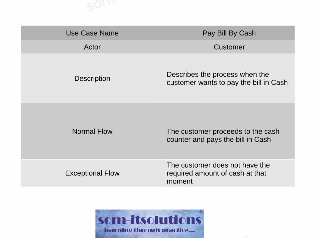
Use Case Name Pay Bill By Cash
Actor Customer
DescriptionDescribes the process when the customer wants to pay the bill in Cash
Normal Flow The customer proceeds to the cash counter and pays the bill in Cash
Exceptional FlowThe customer does not have the required amount of cash at that moment

Use Case Name Pay Bill By Cheque
Actor Customer
DescriptionDescribes the process when the customer wants to pay the bill through Check
Normal FlowThe customer proceeds to the cash counter and pays the bill through check
Exceptional Flow None

Use Case Name Pay Bill By Credit Card
Actor Customer
DescriptionDescribes the process when the customer wants to pay the bill through Credit Card
Normal FlowThe customer proceeds to the cash counter and pays the bill through Credit Card
Exceptional FlowThe customer does not have the required credit amount in his credit card account

Relationships between Use Cases
● Include
● Extend

Include Relationship
● Represents the inclusion of the functionality of one use case within another
● Arrow is drawn from the base use case to the used use case
● Write << include >> above arrowhead line

Restaurant System – Use Case Diagram

Class Diagrams

What is a Class Diagram
● A Class Diagram is a diagram describing the static structure of a system
● It shows the system's ● classes● attributes● operations (or methods),● Relationships among the classes.

Essential elements of a UML Class Diagram
● Class● Attributes● Operations● Relationships
➔ Dependency➔ Aggregation➔ Composition➔ Inheritance➔ Realization
● Constraint Rules and Notes

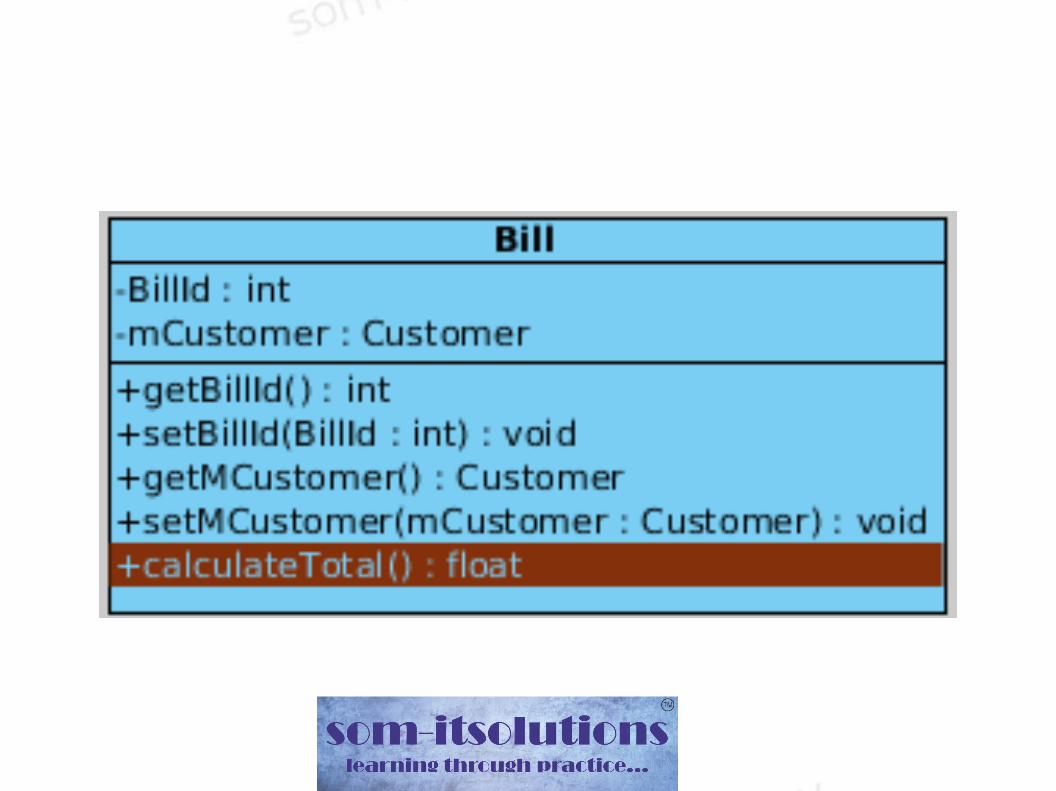
Class
● A class in UML Class Diagram has
➔ Attributes ( state)➔ Operations (behavior)
● It has static relationship with the other classes of the system
● Each Atrribute & Operation has different visibilities
➔ “+” for public➔ “-” for private➔ “#” for protected

Relationship between classes

The relationships are called as● Dependency : class A uses class B● Aggregation : class A has a class B● Composition : class A owns a class B● Inheritance : class B is a Class A (or class A is
extended by class B)● Realization : class B realizes Class A (or interface
A is realized by class B)

Dependency
Dependency is represented when a reference to one class is passed in as a method parameter to another class or a local variable of another class is created in a member function. For example, an instance of class B is passed in to a method of class A:
● public class A {
public void doSomething(B b) {.......
}
● public class A{
public void doSomething(){
B b = new B();
.........
}

Aggregation
If class A stored the reference to class B for later use we would have a different relationship called Aggregation. A common and obvious example of Aggregation would be via setter injection:
● public class A {
private B _b;
public void setB(B b) { _b = b; }

Composition
● Aggregation is the weaker form of object containment (one object contains other objects). The stronger form is called Composition. In Composition the containing object is responsible for the creation and life cycle of the contained object (either directly or indirectly)
● In the next three slides you will see the example of composition

Composition – via member initialization
● public class A {
private B _b = new B();

Composition - via constructor initialization
● public class A {
private B _b;
public A() {
_b = new B();
} // default constructor

Composition – via lazy initialization
public class A {
private B _b;
public void doSomethingUniqueToB() {
if (null == _b) {
_b = new B();
}
return _b.doSomething();
} // doSomethingUniqueToB()

Inheritance
public class A {
...
} // class A
public class B extends A {
....
} // class B

Realization
public interface A {
...
} // interface A
public class B implements A {
...
} // class B

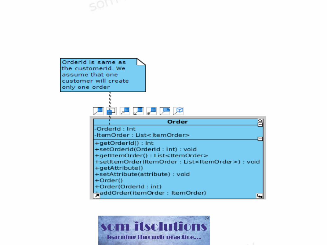
Case Study – Restaurant System
Find out the nouns from the Use Case Analysis. These are likely to be major classes.
First the classes for the major Actors● Customer● Receptionist● Waiter● Cashier

Case Study – Restaurant System
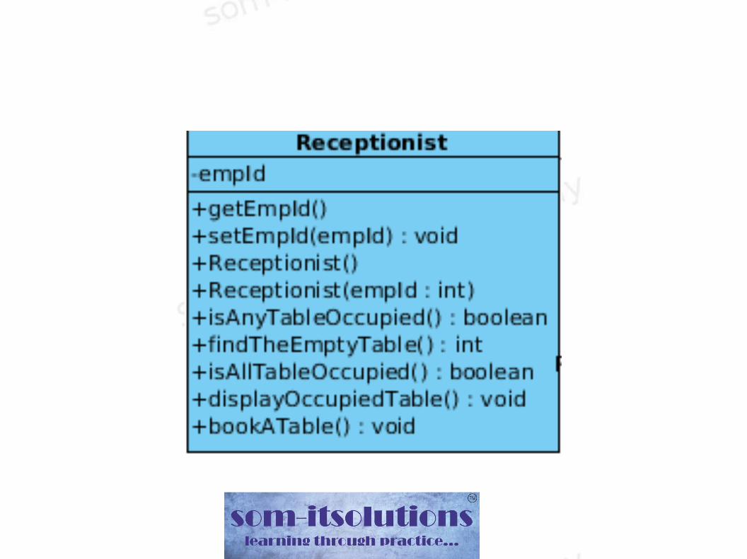


Refactoring – Introducing Employee Class


Sequence Diagram

● UML Specifies a number of interaction diagrams to model dynamic aspects of the system
● Dynamic aspects of the system– Messages moving among objects of classes
– Flow of control among objects
– Sequences of events
Dynamic Diagram
The most important dynamic diagrams are - ● Interaction Diagrams - Set of objects or roles and
the messages that can be passed among them– Sequence Diagrams - emphasize time ordering
– Communication Diagrams - emphasize structural ordering
● State Diagrams - State machine consisting of states, transitions, events and activities of an object
Sequence Diagram
● Describe the flow of messages, events, actions between objects
● Show concurrent processes and activations● Show time sequences that are not easily
depicted in other diagrams● Typically used during analysis and design to
document and understand the logical flow of your system

Participating Objects
● Squares with object type, optionally preceded by object name and colon
● Object's "life line" represented by dashed vertical line
● Message (method call) indicated by horizontal arrow to other object

Messages
● Messages are (method call) indicated by horizontal arrow to other object
● Dashed arrow back indicates return (optional)● Different arrowheads for normal / concurrent
(asynchronous) methods

Lifetime of Objects
● Creation: arrow with 'new/create' written above it
– notice that an object created after the start of the scenario appears lower than the others
● Deletion: an X at bottom of object's lifeline
– Java doesn't explicitly delete objects; they fall out of scope and are garbage-collected