UM2188 User manual - st.com · UM2188 User manual Getting started with the X-NUCLEO-PLM01A1...
19
June 2017 DocID030447 Rev 1 1/19 www.st.com UM2188 User manual Getting started with the X-NUCLEO-PLM01A1 expansion board based on ST7580 for STM32 Nucleo Introduction The X-NUCLEO-PLM01A1 expansion board for STM32 Nucleo is based on the ST7580 FSK, PSK multi-mode power line networking system-on-chip. It provides an affordable and easy-to-use solution for the development of connectivity applications based on power line communication. It lets you easily evaluate the communication features of the ST7580 based on a DC two-wire link between two boards. You can also perform evaluation on an AC power line by connecting the X-NUCLEO-PLM01A1 to an STEVAL-XPLM01CPL board providing effective AC coupling and isolation. The X-NUCLEO-PLM01A1 is interfaced with the STM32 controller via UART and GPIO pins and is compatible with the Arduino UNO R3 (default configuration) and ST morpho (optional) connectors. Figure 1: X-NUCLEO-PLM01A1 expansion board
-
Upload
duongkhuong -
Category
Documents
-
view
230 -
download
3
Transcript of UM2188 User manual - st.com · UM2188 User manual Getting started with the X-NUCLEO-PLM01A1...

June 2017 DocID030447 Rev 1 1/19
www.st.com
UM2188 User manual
Getting started with the X-NUCLEO-PLM01A1 expansion board based on ST7580 for STM32 Nucleo
Introduction The X-NUCLEO-PLM01A1 expansion board for STM32 Nucleo is based on the ST7580 FSK, PSK multi-mode power line networking system-on-chip. It provides an affordable and easy-to-use solution for the development of connectivity applications based on power line communication. It lets you easily evaluate the communication features of the ST7580 based on a DC two-wire link between two boards.
You can also perform evaluation on an AC power line by connecting the X-NUCLEO-PLM01A1 to an STEVAL-XPLM01CPL board providing effective AC coupling and isolation. The X-NUCLEO-PLM01A1 is interfaced with the STM32 controller via UART and GPIO pins and is compatible with the Arduino UNO R3 (default configuration) and ST morpho (optional) connectors.
Figure 1: X-NUCLEO-PLM01A1 expansion board

Contents UM2188
2/19 DocID030447 Rev 1
Contents
1 Typical applications ........................................................................ 5
2 Getting started ................................................................................. 6
2.1 Hardware requirements ..................................................................... 6
2.2 System requirements ........................................................................ 6
2.3 Board setup ....................................................................................... 6
3 Hardware description ...................................................................... 9
3.1 Interconnections details .................................................................... 9
3.2 UART interconnection options ......................................................... 10
3.3 Current measurement ..................................................................... 10
3.4 X-NUCLEO-PLM01A1 component placement details ..................... 11
3.5 ST7580 device ................................................................................ 11
4 Schematic diagrams ...................................................................... 13
5 Bill of materials .............................................................................. 16
6 Revision history ............................................................................ 18

UM2188 List of tables
DocID030447 Rev 1 3/19
List of tables
Table 1: Left connector: connection details ................................................................................................ 9 Table 2: Right connector: connection details .............................................................................................. 9 Table 3: ST7580 and STM32 Nucleo UART interface options ................................................................. 10 Table 4: X-NUCLEO-PLM01A1 bill of materials ....................................................................................... 16 Table 5: Document revision history .......................................................................................................... 18

List of figures UM2188
4/19 DocID030447 Rev 1
List of figures
Figure 1: X-NUCLEO-PLM01A1 expansion board ..................................................................................... 1 Figure 2: X-NUCLEO-PLM01A1 expansion board connected to an STM32 Nucleo board ....................... 6 Figure 3: X-NUCLEO-PLM01A1 expansion board and STM32 Nucleo board jumper configuration ......... 7 Figure 4: X-NUCLEO-PLM01A1 expansion board basic evaluation setup ................................................ 8 Figure 5: X-NUCLEO-PLM01A1 expansion board component placement details ................................... 11 Figure 6: ST7580 block diagram ............................................................................................................... 12 Figure 7: X-NUCLEO-PLM01A1 schematic diagram (1 of 3) ................................................................... 13 Figure 8: X-NUCLEO-PLM01A1 schematic diagram (2 of 3) ................................................................... 14 Figure 9: X-NUCLEO-PLM01A1 schematic diagram (3 of 3) ................................................................... 15

UM2188 Typical applications
DocID030447 Rev 1 5/19
1 Typical applications
The X-NUCLEO-PLM01A1 expansion board features:
STM32 Nucleo expansion board based on the ST7580 power line networking system-on-chip
ST7580 main characteristics:
FSK, PSK modem for robust wireline communication up to 28.8 kbps
8-18 V analog supply voltage
3.3 V digital supply
Output transmitted signal capability up to 14 Vp-p, 1 Arms
Frequency range 9-250 kHz
TX and RX filters on board optimized for the CENELEC B (95-125 kHz) frequencyband, suitable for IoT / Smart Home / Smart City applications
Compatible with STM32 Nucleo boards
Equipped with Arduino UNO R3 connectors
Example firmware available for point-to-point communication, compatible withSTM32Cube firmware
RoHS compliant
The X-NUCLEO-PLM01A1 expansion board can be used for the ST7580 device evaluation in multiple applications:
automatic meter reading
home and building automation
smart lighting
industrial monitoring and control
wireless fire and security alarm systems
A point-to-point communication protocol demo is available to be tested with the board.a
a For further details refer to the X-CUBE-PLM1 databrief available at www.st.com.

Getting started UM2188
6/19 DocID030447 Rev 1
2 Getting started
2.1 Hardware requirements
The X-NUCLEO-PLM01A1 is an expansion board for the STM32 Nucleo boards. To function correctly, it must be plugged on an STM32 Nucleo board through the Arduino™ UNO R3 connectors as shown in the figure below. Information on STM32 Nucleo is available at http://www.st.com/stm32nucleo.
Figure 2: X-NUCLEO-PLM01A1 expansion board connected to an STM32 Nucleo board
The X-NUCLEO-PLM01A1 can be connected to any STM32 Nucleo board, even though complete testing was performed on the NUCLEO-F401RE and NUCLEO-L053R8 development boards.
2.2 System requirements
Using the STM32 Nucleo boards with the X-NUCLEO-PLM01A1 expansion board requires:
a Windows PC to control the board through a serial terminal;
a USB type A to Mini-B USB cable to connect the STM32 Nucleo board to the PC;
a DC power supply to provide VCC = 8-18 V (12 V typical) for ST7580 analog supply.
2.3 Board setup
To set up the board:
1 Verify the jumper configuration:
on the STM32 Nucleo development board, JP5 closed to pin E5V;
on the X-NUCLEO-PLM01A1 expansion board:
UM2188 Getting started
DocID030447 Rev 1 7/19
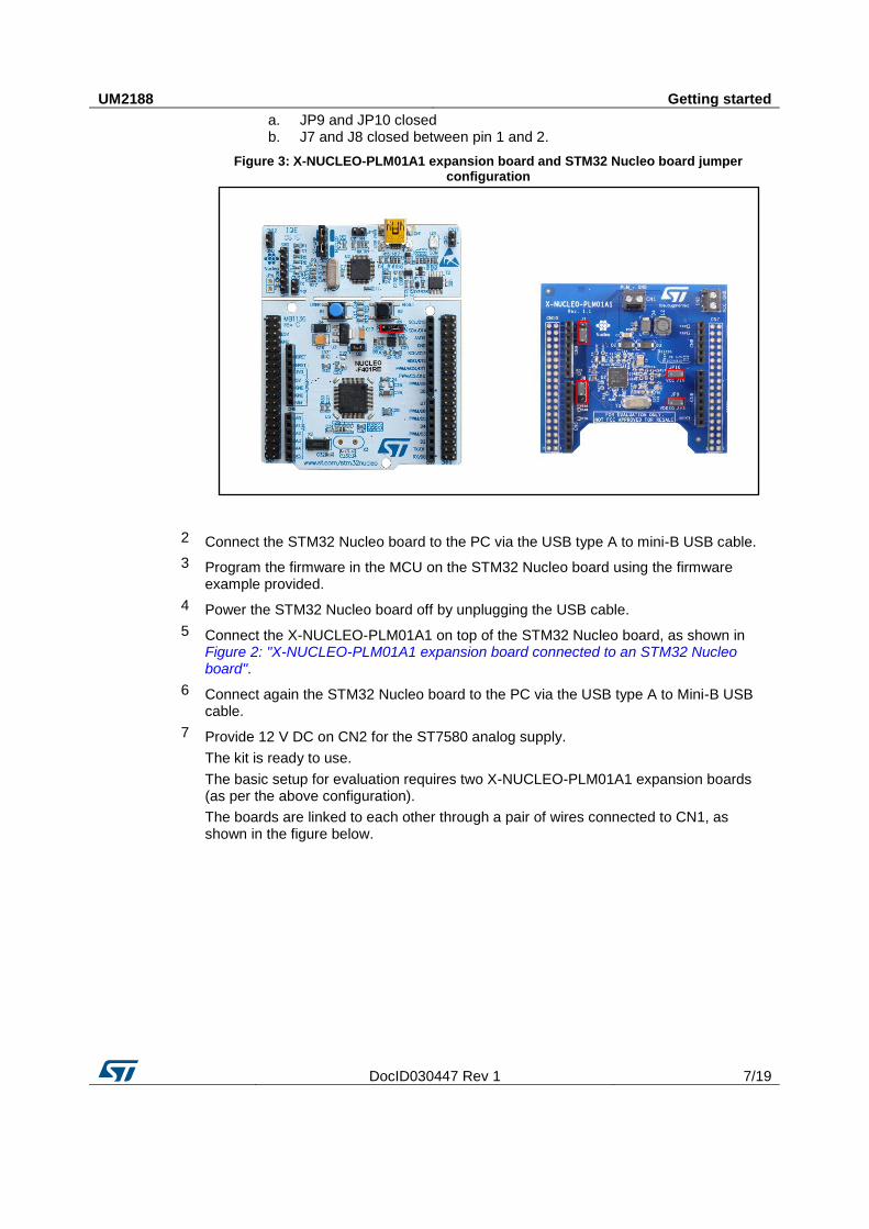
a. JP9 and JP10 closed b. J7 and J8 closed between pin 1 and 2.
Figure 3: X-NUCLEO-PLM01A1 expansion board and STM32 Nucleo board jumper configuration
2 Connect the STM32 Nucleo board to the PC via the USB type A to mini-B USB cable.
3 Program the firmware in the MCU on the STM32 Nucleo board using the firmware example provided.
4 Power the STM32 Nucleo board off by unplugging the USB cable.
5 Connect the X-NUCLEO-PLM01A1 on top of the STM32 Nucleo board, as shown in Figure 2: "X-NUCLEO-PLM01A1 expansion board connected to an STM32 Nucleo board".
6 Connect again the STM32 Nucleo board to the PC via the USB type A to Mini-B USB cable.
7 Provide 12 V DC on CN2 for the ST7580 analog supply.
The kit is ready to use.
The basic setup for evaluation requires two X-NUCLEO-PLM01A1 expansion boards (as per the above configuration).
The boards are linked to each other through a pair of wires connected to CN1, as shown in the figure below.

Getting started UM2188
8/19 DocID030447 Rev 1
Figure 4: X-NUCLEO-PLM01A1 expansion board basic evaluation setup
Pay attention to match PLM and GND when connecting two or more boards, to avoid short-circuiting the PLM signal to GND.

UM2188 Hardware description
DocID030447 Rev 1 9/19
3 Hardware description
3.1 Interconnections details
The tables below show the connection details between the X-NUCLEO-PLM01A1 expansion board and the NUCLEO-L053R8 board.
Table 1: Left connector: connection details
X-NUCLEO-PLM01A1expansion board signals
NUCLEO-L053R8 MCU port
Pin number
Connector name
Signal name
1
CN6 power
NC
3V3 2 IOREF
3 RESET
3V3 4 3V3
5 5V
GND 6 GND
GND 7 GND
VCC 8 VIN
PA0 1
CN8 analog
A0
PA1 2 A1
PA4 3 A2
PB0 4 A3
PL_RX_ON PC1 5 A4
PL_TX_ON PC0 6 A5
Table 2: Right connector: connection details
X-NUCLEO-PLM01A1expansion board signals
NUCLEO-L053R8 MCU port
Pin number
Connector name
Signal name
PB8 10
CN5 digital
D15
PB9 9 D14
AVDD 8 AREF
GND GND 7 GND
T_REQ PA5 6 D13
PA6 5 D12
RXD(1) PA7 4 D11
PB6 3 D10
PC7 2 D9
RXD PA9 1 D8
RXD(1) PA8 8 CN9 digital
D7
TXD (1) PB10 7 D6

Hardware description UM2188
10/19 DocID030447 Rev 1
X-NUCLEO-PLM01A1expansion board signals
NUCLEO-L053R8 MCU port
Pin number
Connector name
Signal name
TXD PB4 6 D5
PB5 5 D4
PB3 4 D3
PA10 3 D2
PA2 2 D1
PLC_RESETN PA3 1 D0
Notes:
(1)Optional connection
3.2 UART interconnection options
The table below shows the UART connection options between the STM32 Nucleo and the ST7580 device hosted on the X-NUCLEO-PLM01A1 expansion board.
These options can be used to enable different configurations in case a signal conflict occurs when using other expansion boards on top of the X-NUCLEO-PLM01A1 expansion board.
Table 3: ST7580 and STM32 Nucleo UART interface options
ST7580 signal Default STM32 port Optional STM32 port – 1 Optional STM32 port – 2
RXD USART1_TX = PA9
Close J8 pin 1-2
USART2_TX = PA3
Close J8 pin 2-3
USART1_TX = PB6
Open J8, solder R68 = 0R
TXD USART1_RX = PA10
Close J7 pin 1-2
USART2_RX = PA2
Close J7 pin 2-3
USART1_RX = PB7
Open J7, solder R67 = 0R
3.3 Current measurement
To monitor the digital and analog consumption jumpers JP9 and JP10 can be respectively used by easily connecting a current probe between pin 1 and 2 of each jumper to perform the measurement.

UM2188 Hardware description
DocID030447 Rev 1 11/19
3.4 X-NUCLEO-PLM01A1 component placement details
Figure 5: X-NUCLEO-PLM01A1 expansion board component placement details
3.5 ST7580 device
The ST7580 FSK, PSK multi-mode power line networking system on chip is based on a dual digital core architecture (a processor engine and a protocol controller core) to guarantee excellent communication performance with a high level of flexibility. It has been built on a multi-power technology with state-of-the-art VLSI CMOS lithography.
A hardware 128-bit AES encryption block (with customizable key management) is available on chip when secure communication is requested.
The on-chip analog front end featuring analog-to-digital and digital-to-analog conversion, automatic gain control and the integrated power amplifier delivering up to 1 A rms output current make the ST7580 a unique system on chip for power line communication.
Safe and performing operations are guaranteed while keeping power consumption and signal distortion levels very low, thus making the ST7580 an ideal platform for the most stringent application requirements and regulatory standards compliance.

Hardware description UM2188
12/19 DocID030447 Rev 1
Figure 6: ST7580 block diagram

UM2188 Schematic diagrams
DocID030447 Rev 1 13/19
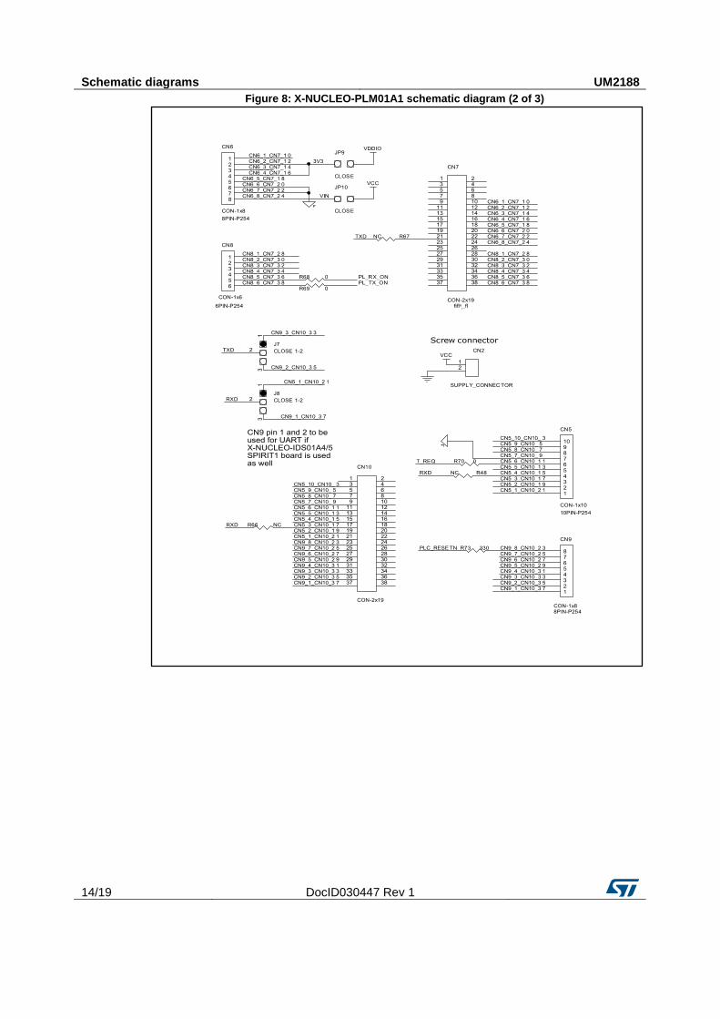
4 Schematic diagrams
Figure 7: X-NUCLEO-PLM01A1 schematic diagram (1 of 3)
Schematic diagrams UM2188
14/19 DocID030447 Rev 1
Figure 8: X-NUCLEO-PLM01A1 schematic diagram (2 of 3)

UM2188 Schematic diagrams
DocID030447 Rev 1 15/19
Figure 9: X-NUCLEO-PLM01A1 schematic diagram (3 of 3)
Bill of materials UM2188
16/19 DocID030447 Rev 1
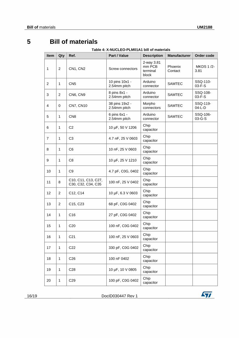
5 Bill of materials Table 4: X-NUCLEO-PLM01A1 bill of materials
Item Qty Ref. Part / Value Description Manufacturer Order code
1 2 CN1, CN2 Screw connectors
2-way 3.81mm PCBterminalblock
Phoenix Contact
MKDS 1 /2-3.81
2 1 CN5 10 pins 10x1 - 2.54mm pitch
Arduino connector
SAMTEC SSQ-110-03-F-S
3 2 CN6, CN9 8 pins 8x1 - 2.54mm pitch
Arduino connector
SAMTEC SSQ-108-03-F-S
4 0 CN7, CN10 38 pins 19x2 - 2.54mm pitch
Morpho connectors
SAMTEC SSQ-119-04-L-D
5 1 CN8 6 pins 6x1 - 2.54mm pitch
Arduino connector
SAMTEC SSQ-106-03-G-S
6 1 C2 10 µF, 50 V 1206 Chip capacitor
7 1 C3 4.7 nF, 25 V 0603 Chip capacitor
8 1 C6 10 nF, 25 V 0603 Chip capacitor
9 1 C8 10 µF, 25 V 1210 Chip capacitor
10 1 C9 4.7 pF, C0G, 0402 Chip capacitor
11 8 C10, C11, C13, C27, C30, C32, C34, C35
100 nF, 25 V 0402 Chip capacitor
12 2 C12, C14 10 µF, 6.3 V 0603 Chip capacitor
13 2 C15, C23 68 pF, C0G 0402 Chip capacitor
14 1 C16 27 pF, C0G 0402 Chip capacitor
15 1 C20 100 nF, C0G 0402 Chip capacitor
16 1 C21 100 nF, 25 V 0603 Chip capacitor
17 1 C22 330 pF, C0G 0402 Chip capacitor
18 1 C26 100 nF 0402 Chip capacitor
19 1 C28 10 µF, 10 V 0805 Chip capacitor
20 1 C29 100 pF, C0G 0402 Chip capacitor

UM2188 Bill of materials
DocID030447 Rev 1 17/19
Item Qty Ref. Part / Value Description Manufacturer Order code
21 1 C31 4.7 µF, 4 V 0402 Chip capacitor
22 1 DL1 SMD 0603 Green LED
23 1 DL2 SMD 0603 Red LED
24 2 D2,D3 STPS1L30A SMB
25 1 D4 SM6T6V8CA SMB
26 1 FB1 BLM21PG331SN1 0603
Ferrite bead
27 2 J7, J8 3x1 2.54 mm pitch Jumper
28 2 JP9, JP10 2x1 2.54 mm pitch Jumper
29 1 L2 B82462G4224M 6.3x6.3 mm
SMD inductor
30 2 RN2,RN3 10 K Resistor array
BOURNS CAY10-103J4LF
31 1 R5 150 R 0603 Chip resistor
32 1 R6 33 k 0402 Chip resistor
33 5 R9,R10,R23,R30,R47 10 K 0402 Chip resistor
34 1 R11 91 R 0402 Chip resistor
35 3 R12,R58,R64 24 K 0402 Chip resistor
36 1 R15 4k7 0402 Chip resistor
37 1 R16 2 k 0402 Chip resistor
38 2 R17,R19 47 K 0402 Chip resistor
39 2 R31,R32 560 R 0402 Chip resistor
40 0 R48,R66,R67 NOT MOUNTED Chip resistor
41 3 R68,R69,R70 0 R 0402 Chip resistor
42 1 R73 330 R 0402 Chip resistor
43 1 U2 ST7580 QFN48 with exposed pad
44 1 Y3 8.0000 MHz HC49U
Quartz crystal
RS 478-9347

Revision history UM2188
18/19 DocID030447 Rev 1
6 Revision history Table 5: Document revision history
Date Revision Changes
28-Jun-2017 1 Initial release.
UM2188
DocID030447 Rev 1 19/19
IMPORTANT NOTICE – PLEASE READ CAREFULLY
STMicroelectronics NV and its subsidiaries (“ST”) reserve the right to make changes, corrections, enhancements, modifications , and improvements to ST products and/or to this document at any time without notice. Purchasers should obtain the latest relevant information on ST products before placing orders. ST products are sold pursuant to ST’s terms and conditions of sale in place at the time of order acknowledgement.
Purchasers are solely responsible for the choice, selection, and use of ST products and ST assumes no liability for application assistance or the design of Purchasers’ products.
No license, express or implied, to any intellectual property right is granted by ST herein.
Resale of ST products with provisions different from the information set forth herein shall void any warranty granted by ST for such product.
ST and the ST logo are trademarks of ST. All other product or service names are the property of their respective owners.
Information in this document supersedes and replaces information previously supplied in any prior versions of this document.
© 2017 STMicroelectronics – All rights reserved