UM0784 User manual - STMicroelectronics...UM0784 User interface Doc ID 16215 Rev 1 5/25 2 User...
25
September 2009 Doc ID 16215 Rev 1 1/25 UM0784 User manual STM8L1526-EVAL demonstration firmware 1 Introduction This document describes the demonstration firmware running on the STM8L1526-EVAL evaluation board. You can use it to evaluate the capabilities of the microcontroller and the on-board peripherals. The evaluation board is delivered with the demonstration firmware stored in the Flash program memory of the microcontroller. The firmware is based on the STM8L15x firmware library, and provides an example of how to use this library. It is divided into various smaller demonstration applications (demos). In case the STM8L1526-EVAL evaluation board is not factory-programmed or the demonstration application has been erased, you can reprogram the demonstration firmware into the STM8L15x Flash memory by following the instructions provided in Section 4. For more information about the evaluation board itself, please read the evaluation board user manual. www.st.com
Transcript of UM0784 User manual - STMicroelectronics...UM0784 User interface Doc ID 16215 Rev 1 5/25 2 User...
September 2009 Doc ID 16215 Rev 1 1/25
UM0784User manual
STM8L1526-EVAL demonstration firmware
1 Introduction
This document describes the demonstration firmware running on the STM8L1526-EVAL evaluation board. You can use it to evaluate the capabilities of the microcontroller and the on-board peripherals.
The evaluation board is delivered with the demonstration firmware stored in the Flash program memory of the microcontroller.
The firmware is based on the STM8L15x firmware library, and provides an example of how to use this library. It is divided into various smaller demonstration applications (demos).
In case the STM8L1526-EVAL evaluation board is not factory-programmed or the demonstration application has been erased, you can reprogram the demonstration firmware into the STM8L15x Flash memory by following the instructions provided in Section 4.
For more information about the evaluation board itself, please read the evaluation board user manual.
www.st.com

Contents UM0784
2/25 Doc ID 16215 Rev 1
Contents
1 Introduction . . . . . . . . . . . . . . . . . . . . . . . . . . . . . . . . . . . . . . . . . . . . . . . . 1
2 User interface . . . . . . . . . . . . . . . . . . . . . . . . . . . . . . . . . . . . . . . . . . . . . . 5
2.1 Menu structure . . . . . . . . . . . . . . . . . . . . . . . . . . . . . . . . . . . . . . . . . . . . . . 5
2.2 Documentation conventions . . . . . . . . . . . . . . . . . . . . . . . . . . . . . . . . . . . . 5
2.3 Navigating menus and submenus . . . . . . . . . . . . . . . . . . . . . . . . . . . . . . . 6
3 Demonstration applications . . . . . . . . . . . . . . . . . . . . . . . . . . . . . . . . . . . 7
3.1 Menu overview . . . . . . . . . . . . . . . . . . . . . . . . . . . . . . . . . . . . . . . . . . . . . . 7
3.2 Welcome screen and main menu . . . . . . . . . . . . . . . . . . . . . . . . . . . . . . . . 7
3.3 Help mode . . . . . . . . . . . . . . . . . . . . . . . . . . . . . . . . . . . . . . . . . . . . . . . . . 8
3.4 Calendar demo . . . . . . . . . . . . . . . . . . . . . . . . . . . . . . . . . . . . . . . . . . . . . . 8
3.4.1 Setting the time . . . . . . . . . . . . . . . . . . . . . . . . . . . . . . . . . . . . . . . . . . . . 8
3.4.2 Setting the date . . . . . . . . . . . . . . . . . . . . . . . . . . . . . . . . . . . . . . . . . . . . 9
3.4.3 Setting the alarm . . . . . . . . . . . . . . . . . . . . . . . . . . . . . . . . . . . . . . . . . . 11
3.5 Thermometer demo . . . . . . . . . . . . . . . . . . . . . . . . . . . . . . . . . . . . . . . . . 12
3.6 IDD measurement demo . . . . . . . . . . . . . . . . . . . . . . . . . . . . . . . . . . . . . . 13
3.7 Low power demo . . . . . . . . . . . . . . . . . . . . . . . . . . . . . . . . . . . . . . . . . . . 13
3.7.1 Run mode . . . . . . . . . . . . . . . . . . . . . . . . . . . . . . . . . . . . . . . . . . . . . . . 13
3.7.2 Wait for interrupt mode . . . . . . . . . . . . . . . . . . . . . . . . . . . . . . . . . . . . . 14
3.7.3 Wait for event mode . . . . . . . . . . . . . . . . . . . . . . . . . . . . . . . . . . . . . . . . 15
3.7.4 Active-Halt mode . . . . . . . . . . . . . . . . . . . . . . . . . . . . . . . . . . . . . . . . . . 16
3.7.5 Halt mode . . . . . . . . . . . . . . . . . . . . . . . . . . . . . . . . . . . . . . . . . . . . . . . 18
3.8 Audio demo . . . . . . . . . . . . . . . . . . . . . . . . . . . . . . . . . . . . . . . . . . . . . . . 19
3.8.1 Voice recorder demo . . . . . . . . . . . . . . . . . . . . . . . . . . . . . . . . . . . . . . . 19
3.8.2 Voice player demo . . . . . . . . . . . . . . . . . . . . . . . . . . . . . . . . . . . . . . . . . 20
3.9 About menu . . . . . . . . . . . . . . . . . . . . . . . . . . . . . . . . . . . . . . . . . . . . . . . 21
4 Upgrading the demonstration firmware . . . . . . . . . . . . . . . . . . . . . . . . 22
5 STM8L15x peripherals used . . . . . . . . . . . . . . . . . . . . . . . . . . . . . . . . . . 23
6 Revision history . . . . . . . . . . . . . . . . . . . . . . . . . . . . . . . . . . . . . . . . . . . 24
UM0784 List of tables
Doc ID 16215 Rev 1 3/25
List of tables
Table 1. Documentation conventions . . . . . . . . . . . . . . . . . . . . . . . . . . . . . . . . . . . . . . . . . . . . . . . . . 5Table 2. Peripherals used. . . . . . . . . . . . . . . . . . . . . . . . . . . . . . . . . . . . . . . . . . . . . . . . . . . . . . . . . 23Table 3. Document revision history . . . . . . . . . . . . . . . . . . . . . . . . . . . . . . . . . . . . . . . . . . . . . . . . . 24

List of figures UM0784
4/25 Doc ID 16215 Rev 1
List of figures
Figure 1. Menu structure and navigation . . . . . . . . . . . . . . . . . . . . . . . . . . . . . . . . . . . . . . . . . . . . . . . 5Figure 2. Menu overview . . . . . . . . . . . . . . . . . . . . . . . . . . . . . . . . . . . . . . . . . . . . . . . . . . . . . . . . . . . 7Figure 3. Welcome message . . . . . . . . . . . . . . . . . . . . . . . . . . . . . . . . . . . . . . . . . . . . . . . . . . . . . . . . 7Figure 4. Main menu . . . . . . . . . . . . . . . . . . . . . . . . . . . . . . . . . . . . . . . . . . . . . . . . . . . . . . . . . . . . . . 7Figure 5. Help mode submenus. . . . . . . . . . . . . . . . . . . . . . . . . . . . . . . . . . . . . . . . . . . . . . . . . . . . . . 8Figure 6. Time adjust message . . . . . . . . . . . . . . . . . . . . . . . . . . . . . . . . . . . . . . . . . . . . . . . . . . . . . . 9Figure 7. Time show message. . . . . . . . . . . . . . . . . . . . . . . . . . . . . . . . . . . . . . . . . . . . . . . . . . . . . . . 9Figure 8. Date Adjust message . . . . . . . . . . . . . . . . . . . . . . . . . . . . . . . . . . . . . . . . . . . . . . . . . . . . . 10Figure 9. Date Adjust message . . . . . . . . . . . . . . . . . . . . . . . . . . . . . . . . . . . . . . . . . . . . . . . . . . . . . 10Figure 10. Alarm Adjust message . . . . . . . . . . . . . . . . . . . . . . . . . . . . . . . . . . . . . . . . . . . . . . . . . . . . 11Figure 11. Alarm show message . . . . . . . . . . . . . . . . . . . . . . . . . . . . . . . . . . . . . . . . . . . . . . . . . . . . . 11Figure 12. Temperature in degrees Celsius message . . . . . . . . . . . . . . . . . . . . . . . . . . . . . . . . . . . . . 12Figure 13. Temperature in degrees Fahrenheit message . . . . . . . . . . . . . . . . . . . . . . . . . . . . . . . . . . 12Figure 14. Temperature sensor error message . . . . . . . . . . . . . . . . . . . . . . . . . . . . . . . . . . . . . . . . . . 12Figure 15. IDD measurement message . . . . . . . . . . . . . . . . . . . . . . . . . . . . . . . . . . . . . . . . . . . . . . . . 13Figure 16. IDD Run mode message . . . . . . . . . . . . . . . . . . . . . . . . . . . . . . . . . . . . . . . . . . . . . . . . . . . 13Figure 17. Run mode frequency message. . . . . . . . . . . . . . . . . . . . . . . . . . . . . . . . . . . . . . . . . . . . . . 13Figure 18. WFI wait for EXTI message . . . . . . . . . . . . . . . . . . . . . . . . . . . . . . . . . . . . . . . . . . . . . . . . 14Figure 19. Exit from WFI with EXTI message . . . . . . . . . . . . . . . . . . . . . . . . . . . . . . . . . . . . . . . . . . . 14Figure 20. WFI wait for alarm message . . . . . . . . . . . . . . . . . . . . . . . . . . . . . . . . . . . . . . . . . . . . . . . . 15Figure 21. Exit from WFI with alarm message . . . . . . . . . . . . . . . . . . . . . . . . . . . . . . . . . . . . . . . . . . . 15Figure 22. WFE wait for EXTI message. . . . . . . . . . . . . . . . . . . . . . . . . . . . . . . . . . . . . . . . . . . . . . . . 15Figure 23. Exit from WFE with EXTI message. . . . . . . . . . . . . . . . . . . . . . . . . . . . . . . . . . . . . . . . . . . 16Figure 24. WFE wait for comparator interrupt message . . . . . . . . . . . . . . . . . . . . . . . . . . . . . . . . . . . 16Figure 25. Exit from WFE with comparator interrupt message . . . . . . . . . . . . . . . . . . . . . . . . . . . . . . 16Figure 26. Active Halt wait for EXTI message . . . . . . . . . . . . . . . . . . . . . . . . . . . . . . . . . . . . . . . . . . . 17Figure 27. Exit from Active-halt with EXTI message . . . . . . . . . . . . . . . . . . . . . . . . . . . . . . . . . . . . . . 17Figure 28. Active Halt wait for alarm message . . . . . . . . . . . . . . . . . . . . . . . . . . . . . . . . . . . . . . . . . . 17Figure 29. Exit from Active-halt with alarm message. . . . . . . . . . . . . . . . . . . . . . . . . . . . . . . . . . . . . . 17Figure 30. Halt wait for EXTI message . . . . . . . . . . . . . . . . . . . . . . . . . . . . . . . . . . . . . . . . . . . . . . . . 18Figure 31. Exit from Halt with EXTI message . . . . . . . . . . . . . . . . . . . . . . . . . . . . . . . . . . . . . . . . . . . 18Figure 32. Halt wait for comparator interrupt message . . . . . . . . . . . . . . . . . . . . . . . . . . . . . . . . . . . . 18Figure 33. Exit from Halt with comparator interrupt message . . . . . . . . . . . . . . . . . . . . . . . . . . . . . . . 19Figure 34. Start voice recorder message. . . . . . . . . . . . . . . . . . . . . . . . . . . . . . . . . . . . . . . . . . . . . . . 19Figure 35. Erase Flash message . . . . . . . . . . . . . . . . . . . . . . . . . . . . . . . . . . . . . . . . . . . . . . . . . . . . . 19Figure 36. Voice recorder message. . . . . . . . . . . . . . . . . . . . . . . . . . . . . . . . . . . . . . . . . . . . . . . . . . . 20Figure 37. Stop voice recorder message . . . . . . . . . . . . . . . . . . . . . . . . . . . . . . . . . . . . . . . . . . . . . . . 20Figure 38. End voice recorder message . . . . . . . . . . . . . . . . . . . . . . . . . . . . . . . . . . . . . . . . . . . . . . . 20Figure 39. Voice Player menu message . . . . . . . . . . . . . . . . . . . . . . . . . . . . . . . . . . . . . . . . . . . . . . . 20Figure 40. Play voice recorded message. . . . . . . . . . . . . . . . . . . . . . . . . . . . . . . . . . . . . . . . . . . . . . . 21Figure 41. Stop recorded wave message . . . . . . . . . . . . . . . . . . . . . . . . . . . . . . . . . . . . . . . . . . . . . . 21Figure 42. Displaying the demonstration firmware version . . . . . . . . . . . . . . . . . . . . . . . . . . . . . . . . . 21
UM0784 User interface
Doc ID 16215 Rev 1 5/25
2 User interface
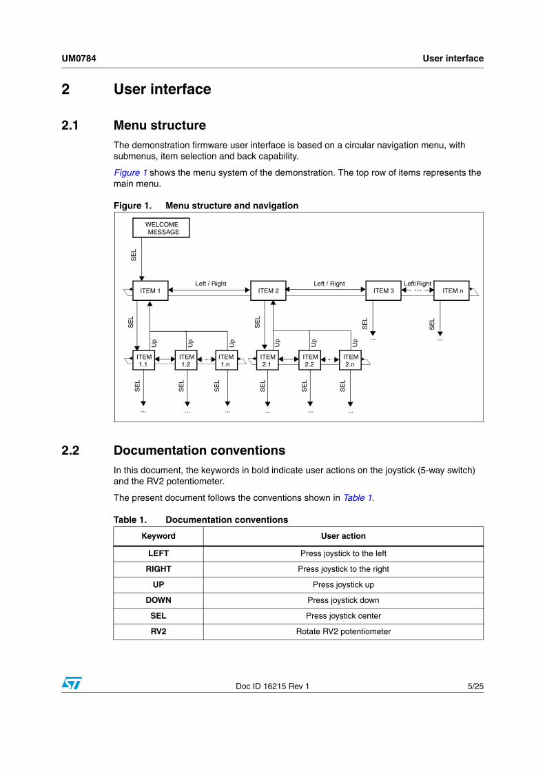
2.1 Menu structureThe demonstration firmware user interface is based on a circular navigation menu, with submenus, item selection and back capability.
Figure 1 shows the menu system of the demonstration. The top row of items represents the main menu.
Figure 1. Menu structure and navigation
2.2 Documentation conventionsIn this document, the keywords in bold indicate user actions on the joystick (5-way switch) and the RV2 potentiometer.
The present document follows the conventions shown in Table 1.
...
......
Up
Up
Up
Up
Up
Up ... ...
...
Left / Right Left / Right Left/Right
WELCOMEMESSAGE
ITEM 1 ITEM 2 ITEM 3 ITEM n
ITEM 1.1
ITEM 1.2
ITEM 1.n
ITEM 2.1
ITEM 2.2
ITEM 2.n
SE
L
SE
L
SE
L
SE
L
... ... ... ... ...
SE
LS
EL
SE
L
SE
L
SE
L
SE
L
SE
L
Table 1. Documentation conventions
Keyword User action
LEFT Press joystick to the left
RIGHT Press joystick to the right
UP Press joystick up
DOWN Press joystick down
SEL Press joystick center
RV2 Rotate RV2 potentiometer

User interface UM0784
6/25 Doc ID 16215 Rev 1
2.3 Navigating menus and submenusTo navigate the menus and submenus, perform the following actions as required:
RIGHT: Navigates to the next menu or submenu items on the right.
LEFT: Navigates to the next menu or submenu items on the left.
SEL: Enters submenu.
UP: Exits from a submenu.
UM0784 Demonstration applications
Doc ID 16215 Rev 1 7/25
3 Demonstration applications
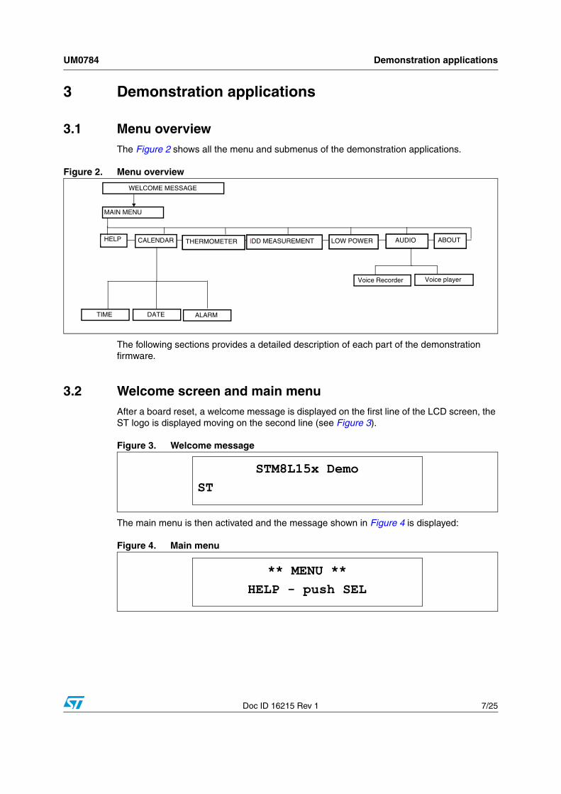
3.1 Menu overviewThe Figure 2 shows all the menu and submenus of the demonstration applications.
Figure 2. Menu overview
The following sections provides a detailed description of each part of the demonstration firmware.
3.2 Welcome screen and main menuAfter a board reset, a welcome message is displayed on the first line of the LCD screen, the ST logo is displayed moving on the second line (see Figure 3).
Figure 3. Welcome message
The main menu is then activated and the message shown in Figure 4 is displayed:
Figure 4. Main menu
ABOUT
WELCOME MESSAGE
HELP
MAIN MENU
Voice Recorder Voice player
AUDIOCALENDAR IDD MEASUREMENT
TIME DATE ALARM
THERMOMETER LOW POWER
STM8L15x DemoST
** MENU **HELP - push SEL
Demonstration applications UM0784
8/25 Doc ID 16215 Rev 1
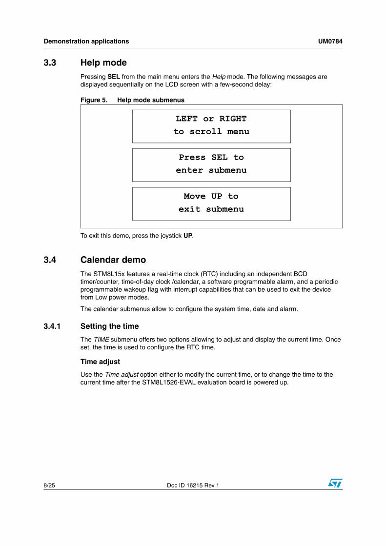
3.3 Help modePressing SEL from the main menu enters the Help mode. The following messages are displayed sequentially on the LCD screen with a few-second delay:
Figure 5. Help mode submenus
To exit this demo, press the joystick UP.
3.4 Calendar demoThe STM8L15x features a real-time clock (RTC) including an independent BCD timer/counter, time-of-day clock /calendar, a software programmable alarm, and a periodic programmable wakeup flag with interrupt capabilities that can be used to exit the device from Low power modes.
The calendar submenus allow to configure the system time, date and alarm.
3.4.1 Setting the time
The TIME submenu offers two options allowing to adjust and display the current time. Once set, the time is used to configure the RTC time.
Time adjust
Use the Time adjust option either to modify the current time, or to change the time to the current time after the STM8L1526-EVAL evaluation board is powered up.
LEFT or RIGHTto scroll menu
Press SEL toenter submenu
Move UP toexit submenu
UM0784 Demonstration applications
Doc ID 16215 Rev 1 9/25
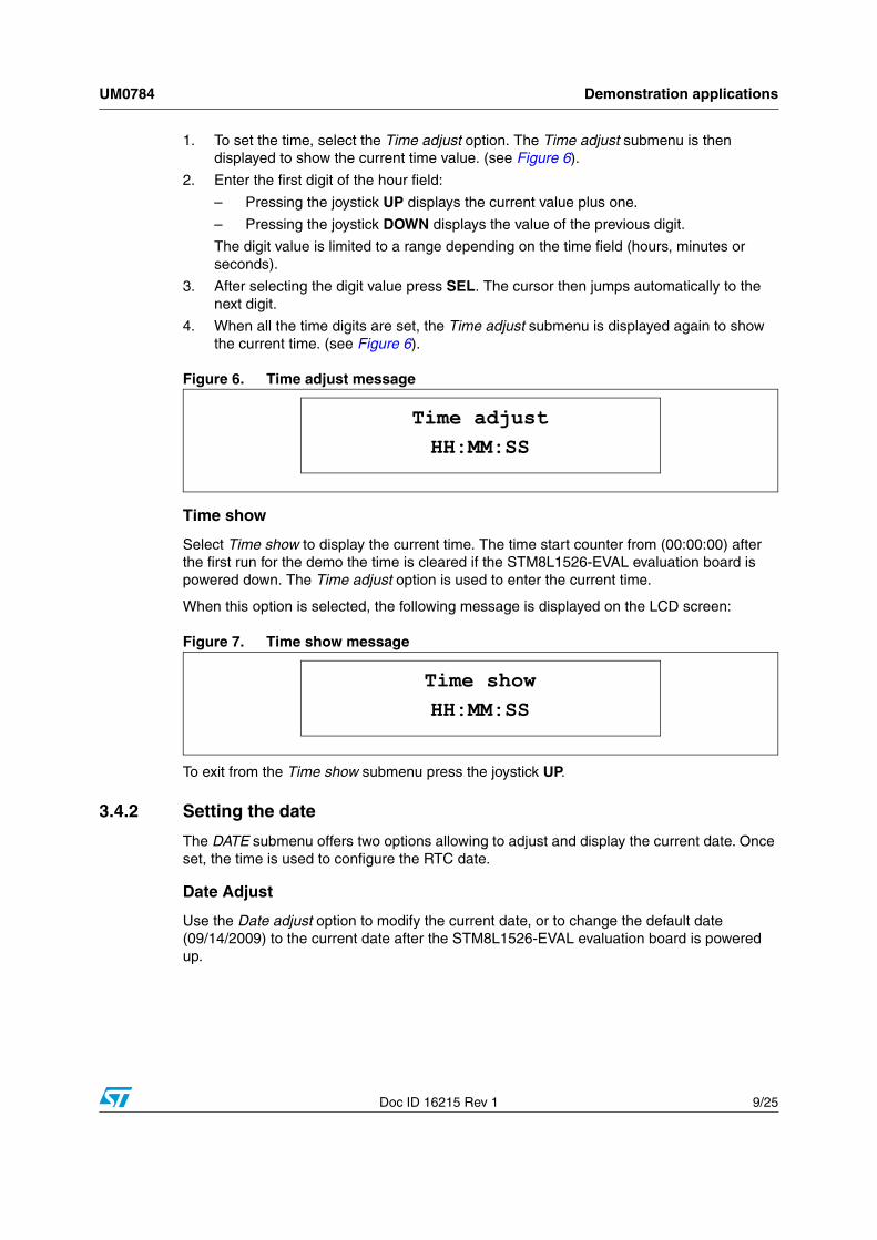
1. To set the time, select the Time adjust option. The Time adjust submenu is then displayed to show the current time value. (see Figure 6).
2. Enter the first digit of the hour field:
– Pressing the joystick UP displays the current value plus one.
– Pressing the joystick DOWN displays the value of the previous digit.
The digit value is limited to a range depending on the time field (hours, minutes or seconds).
3. After selecting the digit value press SEL. The cursor then jumps automatically to the next digit.
4. When all the time digits are set, the Time adjust submenu is displayed again to show the current time. (see Figure 6).
Figure 6. Time adjust message
Time show
Select Time show to display the current time. The time start counter from (00:00:00) after the first run for the demo the time is cleared if the STM8L1526-EVAL evaluation board is powered down. The Time adjust option is used to enter the current time.
When this option is selected, the following message is displayed on the LCD screen:
Figure 7. Time show message
To exit from the Time show submenu press the joystick UP.
3.4.2 Setting the date
The DATE submenu offers two options allowing to adjust and display the current date. Once set, the time is used to configure the RTC date.
Date Adjust
Use the Date adjust option to modify the current date, or to change the default date (09/14/2009) to the current date after the STM8L1526-EVAL evaluation board is powered up.
Time adjustHH:MM:SS
Time showHH:MM:SS

Demonstration applications UM0784
10/25 Doc ID 16215 Rev 1
1. To set the current date, select the Date adjust option. The date then displayed on 8 digits: MM/DD/YYYY (see Figure 8).
2. Enter the first digit of the month field:
– Pressing the joystick UP displays the current value plus one
– Pressing the joystick DOWN displays the previous value.
The digit value is limited to a range depending on the date field (month, day or year).
3. After selecting the digit value press SEL. The cursor then jumps automatically to the next digit.
4. When all the date digits are set, the Date adjust submenu is displayed again to show the current date. (see Figure 8).
Figure 8. Date Adjust message
Date show
Select Date show to display the current date. After power-up, the default date (09/14/209) is displayed till the Date adjust option is used to enter the current date.
The following message is displayed on the LCD screen when this submenu is selected:
Figure 9. Date Adjust message
To exit from this sub menu press the joystick UP push.
Date Adjust09/14/2009
Date ShowMON SEP 09 2009

UM0784 Demonstration applications
Doc ID 16215 Rev 1 11/25
3.4.3 Setting the alarm
Use the ALARM submenu to configure the alarm seconds, minutes and hours.
This submenu offers two options allowing to display or adjust the current alarm.
Alarm adjust
The Alarm adjust option is similar to Time adjust.
After selecting Alarm adjust, or after setting the alarm, the message shown in Figure 10 is displayed.
Figure 10. Alarm Adjust message
Alarm show
Select the Alarm show option to display the current alarm. After power-up, the default alarm time (00:00:00) is displayed till the Alarm adjust option is used to enter a new alarm time.
The following message is displayed on the LCD screen when this submenu is selected:
Figure 11. Alarm show message
To exit from this sub menu press the joystick UP.
Note: 1 When an alarm occurs, the alarm wave is played and can be stopped only by pushing the joystick UP.
2 The alarm can be used also to wake up the system from WFI or Active-halt.
Alarm AdjustHH:MM:SS
Alarm ShowHH:MM:SS

Demonstration applications UM0784
12/25 Doc ID 16215 Rev 1
3.5 Thermometer demoThe STM8L15x microcontroller features an I2C interface that can be connected to any device supporting the I2C protocol including the system management bus (SMBus) mode. An STLM75 I2C temperature sensor (or any compatible device) is mounted on the STM8L1526-EVAL board. It is used to get the instantaneous external temperature.
1. To enter the THERMOMETER menu, press SEL from the main menu. The message shown in Figure 12 is then displayed on the LCD screen.
Figure 12. Temperature in degrees Celsius message
2. Keep the joystick pressed RIGHT to display the temperature in degrees Fahrenheit as shown in Figure 13. Release the joystick to display back the temperature in degrees Celsius.
Figure 13. Temperature in degrees Fahrenheit message
3. To exit the Temperature demo, press the joystick UP.
When a temperature sensor failure occurs, the message shown in Figure 14 is displayed.
Figure 14. Temperature sensor error message
Note: To run this demonstration, the JP7 jumper must be installed in the I2C position.
Temperature+xx.x C
Temperature+xxx.x F
ERR: Set JP7 inI2C pos. & try
UM0784 Demonstration applications
Doc ID 16215 Rev 1 13/25
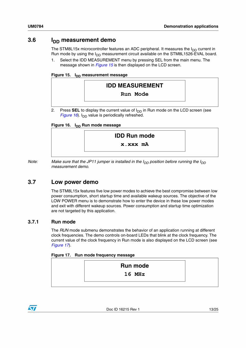
3.6 IDD measurement demoThe STM8L15x microcontroller features an ADC peripheral. It measures the IDD current in Run mode by using the IDD measurement circuit available on the STM8L1526-EVAL board.
1. Select the IDD MEASUREMENT menu by pressing SEL from the main menu. The message shown in Figure 15 is then displayed on the LCD screen.
Figure 15. IDD measurement message
2. Press SEL to display the current value of IDD in Run mode on the LCD screen (see Figure 16). IDD value is periodically refreshed.
Figure 16. IDD Run mode message
Note: Make sure that the JP11 jumper is installed in the IDD position before running the IDD measurement demo.
3.7 Low power demoThe STM8L15x features five low power modes to achieve the best compromise between low power consumption, short startup time and available wakeup sources. The objective of the LOW POWER menu is to demonstrate how to enter the device in these low power modes and exit with different wakeup sources. Power consumption and startup time optimization are not targeted by this application.
3.7.1 Run mode
The RUN mode submenu demonstrates the behavior of an application running at different clock frequencies. The demo controls on-board LEDs that blink at the clock frequency. The current value of the clock frequency in Run mode is also displayed on the LCD screen (see Figure 17).
Figure 17. Run mode frequency message
IDD MEASUREMENTRun Mode
IDD Run modex.xxx mA
Run mode16 MHz
Demonstration applications UM0784
14/25 Doc ID 16215 Rev 1
The Run mode submenu contains four submenu items:● 16 MHz: the application runs at 16 MHz.
● 8 MHz: the application runs at 8 MHz.
● 4 MHz: the application runs at 4 MHz.
● 2 MHz: the application runs at 2 MHz.
Press SEL to select one of the listed Run mode clock frequency.
Press UP to exit from the selected mode and return to the 16 MHz default clock frequency.
3.7.2 Wait for interrupt mode
This menu allows to put the STM8L15x in Wait for interrupt mode (WFI). The software executes the specific sequence of instructions required to enter WFI mode: the CPU clock is stopped, and selected peripherals go on running.
In this demonstration, there are two ways to exit from WFI mode:
● An external interrupt (EXTI) generated by pressing SEL on the joystick exits the STM8L15x from WFI mode:
The LEDs blink until SEL is pressed from the WFI menu (see Figure 18). The system then enters WFI mode and the following message is displayed on the LCD:
Figure 18. WFI wait for EXTI message
The STM8L15x remains in WFI mode unless SEL is pressed on the joystick. The MCU then exits from WFI mode, the system clock frequency is set to 16 MHz, and the application execution resumes. The following message is displayed on the LCD screen:
Figure 19. Exit from WFI with EXTI message
Note: If an alarm occurs when the system is in WFI mode, it is served and a sound is played continuously until the joystick is pressed UP. The application execution then resumes.
Exit: EXTIPress SEL
WFI modeExit: EXTI
UM0784 Demonstration applications
Doc ID 16215 Rev 1 15/25
● The RTC alarm is used to wake up the STM8L15x from WFI mode:
The LEDs blink until SEL is pressed from the WFI menu (see Figure 20). The system then enters WFI mode and the following message is displayed on the LCD:
Figure 20. WFI wait for alarm message
When the alarm time is reached, the system exits from WFI mode, the system clock frequency is set to 16 MHz, and the application execution resumes. The message shown in Figure 21 is then displayed on the LCD screen:
Figure 21. Exit from WFI with alarm message
3.7.3 Wait for event mode
This menu allows to put the STM8L15x in Wait for event mode (WFE). The software executes the specific sequence of instructions required to enter WFE mode: the CPU clock is stopped, and selected peripherals go on running.
In this demonstration, there are two ways to exit from WFE mode:
● An external interrupt (EXTI) generated by pressing SEL on the joystick exits the STM8L15x from WFI mode:
The LEDs blink until SEL is pressed from the WFE menu (see Figure 22). The system then enters WFE mode and the following message is displayed on the LCD:
Figure 22. WFE wait for EXTI message
The STM8L15x remains in WFE mode unless the SEL button is pressed. The MCU then exits from WFE mode, the system clock frequency is set to 16 MHz, and the application execution resumes. The following message is displayed on the LCD screen:
WFI modeWait for Alarm
WFI modeExit: Alarm
Exit: EXTIPress SEL
Demonstration applications UM0784
16/25 Doc ID 16215 Rev 1
Figure 23. Exit from WFE with EXTI message
● A Comparator 1 interrupt can also exit the STM8L15x from WFE mode
This interrupt is generated when the comparator non inverting input (connected to RV2) exceeds the internal reference voltage which is set to 1.22 V.
The LEDs blink until SEL is pressed from WFE menu (see Figure 24). The system then enters WFE mode and the following message is displayed on the LCD:
Figure 24. WFE wait for comparator interrupt message
When Comparator 1 non inverting input exceeds the internal reference voltage, the system exits from WFE mode, and the application execution resumes. The message shown in Figure 25 is then displayed on the LCD screen:
Figure 25. Exit from WFE with comparator interrupt message
Note: If an alarm occurs when the system is in WFE mode, it is served and a sound is played continuously until the joystick is pressed UP. The CPU then returns to WFE mode.
3.7.4 Active-Halt mode
This menu allows to put the STM8L15x in Active-halt mode. The software executes the specific sequence of instructions required to enter Active-halt mode: the CPU clock is stopped except for the RTC.
In this demonstration, there are two ways to exit from Active-halt mode:
● An external interrupt (EXTI) generated by pressing SEL on the joystick exits the STM8L15x from Active-halt mode:
The LEDs continue blinking until SEL is pressed from the Active-halt menu (see Figure 26). The system then enters Active-halt mode and the following message is displayed on the LCD:
WFE modeExit:EXT Event
Exit:COMP EventRotate RV2
WFE modeExit: COMP Event
UM0784 Demonstration applications
Doc ID 16215 Rev 1 17/25
Figure 26. Active Halt wait for EXTI message
The MCU remains in Active-halt mode unless the SEL button is pressed. When SEL is pressed, the MCU exits from Active-halt mode, the system clock frequency is set to 16 MHz, and the application execution resumes.
The following message is displayed on the LCD screen:
Figure 27. Exit from Active-halt with EXTI message
● The RTC alarm wakes up the MCU from Active-halt mode:
The LEDs blink until SEL is pressed from the Active-halt menu (see Figure 28). The system then enters Active-halt mode and the following message is displayed on the LCD.
Figure 28. Active Halt wait for alarm message
When the alarm time is reached, the system exits from Active-halt mode, the system clock frequency is set to 16 MHz, and the application execution resumes. The message shown in Figure 29 is displayed:
Figure 29. Exit from Active-halt with alarm message
Active-halt modeExit: Press SEL
Active-halt modeExit: EXTI
Active-halt modeWait for Alarm
Active-halt modeExit: RTC Alarm

Demonstration applications UM0784
18/25 Doc ID 16215 Rev 1
3.7.5 Halt mode
This menu allows to put the STM8L15x in Halt mode. The software performs the specific sequence of instructions required to enter Halt mode: the CPU and peripheral clocks are stopped, and the device remains powered on.
In this demonstration, there are two ways to exit from halt mode:
● An external interrupt (EXTI) generated by pressing SEL on the joystick exits the STM8L15x from halt mode:
The LEDs blink until SEL is pressed from Halt menu. The system then enters halt mode and the following message is displayed on the LCD:
Figure 30. Halt wait for EXTI message
The STM8L15x remains in Halt mode unless the SEL button is pressed. The MCU then exits from Halt mode, the system clock is set to 16 MHz, and the application execution resumes. The following message is displayed on the LCD:
Figure 31. Exit from Halt with EXTI message
● A Comparator 1 interrupt can also exit the STM8L15x from Halt mode
This interrupt is generated when the non inverting input exceeds the internal reference voltage.
The LEDs blink until SEL is pressed from the Halt menu (see Figure 32). The system then enters Halt mode and the following message is displayed on the LCD:
Figure 32. Halt wait for comparator interrupt message
Exit: EXTIPress SEL
Halt modeExit: EXTI
Exit:COMP Int.Rotate RV2
UM0784 Demonstration applications
Doc ID 16215 Rev 1 19/25
When Comparator 1 non inverting input exceeds the internal reference voltage, the system exits from Halt mode, and the application execution resumes. The message shown in Figure 33 is then displayed on the LCD screen:
Figure 33. Exit from Halt with comparator interrupt message
3.8 Audio demo
3.8.1 Voice recorder demo
The STM8L15x microcontroller features timers and an ADC which can be used for timing and signal acquisition, respectively.
In this demo, Timer 1 (TIM1) is used to generate an update interrupt every 45.35 µs (22.05 kHz), which corresponds to the voice sampling period. This update event triggers the ADC voice acquisition. Voice data is saved on the on-board SPI Flash memory.
When the Voice Recorder is selected from the AUDIO menu by pressing SEL on the joystick, the following message is displayed on the LCD screen:
Figure 34. Start voice recorder message
This message remains displayed until SEL is pressed. The STM8L15x then starts erasing the voice data previously stored on the on-board Flash memory. The message shown in Figure 35 remains displayed until the erase operation is complete.
Figure 35. Erase Flash message
When the erase operation is complete, the message shown in Figure 36 is displayed:
HALT modeExit: COMP Int.
Voice RecorderVoice REC Start
Voice RecorderSPI Flash Erase

Demonstration applications UM0784
20/25 Doc ID 16215 Rev 1
Figure 36. Voice recorder message
When SEL is pressed, the STM8L15x starts recording voice and the displays the message shown in Figure 37:
Figure 37. Stop voice recorder message
To stop recording, press the joystick UP, otherwise the STM8L15x will stop recording automatically after 30 s and the message shown in Figure 38 will be displayed:
Figure 38. End voice recorder message
3.8.2 Voice player demo
The STM8L15x microcontroller features an embedded DAC which can is used to generate output signals.
In this demo, the DAC regenerates the voice signal recorded in the SPI Flash memory. Timer 4 (TIM4) triggers the DAC to generate the voice signal every 45.35 µs (22.05 kHz) which corresponds to the voice sampling period.
When the Voice Player is selected from the AUDIO menu by pressing the SEL on the joystick, The following message remains displayed unless SEL is pressed.:
Figure 39. Voice Player menu message
When SEL is pressed, the STM8L15x starts playing the voice, and the message shown in Figure 40 is displayed.
Voice RecorderRecord:PressSEL
Voice RecorderStop:In 30s/UP
AUDIOVoice Recorder
Voice PlayerRecorded Voice
UM0784 Demonstration applications
Doc ID 16215 Rev 1 21/25
Figure 40. Play voice recorded message
To stop the voice player demo, press the joystick UP. The message shown on Figure 41 is then displayed. Otherwise, the STM8L15x will stop automatically at the end of the wave.
Figure 41. Stop recorded wave message
3.9 About menuThis menu shows the firmware version. When this submenu is selected the message shown in Figure 42 is displayed on the LCD screen:
Figure 42. Displaying the demonstration firmware version
Press the joystick UP to exit this menu.
Recorded VoicePlay
AUDIOVoice Player
STM8L1526-EVALFW Version x.y.z
Upgrading the demonstration firmware UM0784
22/25 Doc ID 16215 Rev 1
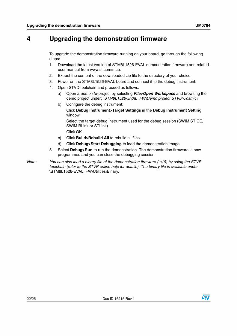
4 Upgrading the demonstration firmware
To upgrade the demonstration firmware running on your board, go through the following steps:
1. Download the latest version of STM8L1526-EVAL demonstration firmware and related user manual from www.st.com/mcu.
2. Extract the content of the downloaded zip file to the directory of your choice.
3. Power on the STM8L1526-EVAL board and connect it to the debug instrument.
4. Open STVD toolchain and proceed as follows:
a) Open a demo.stw project by selecting File>Open Workspace and browsing the demo project under: \STM8L1526-EVAL_FW\Demo\project\STVD\Cosmic\
b) Configure the debug instrument:
Click Debug Instrument>Target Settings in the Debug Instrument Setting window
Select the target debug instrument used for the debug session (SWIM STICE, SWIM RLink or STLink)
Click OK.
c) Click Build>Rebuild All to rebuild all files
d) Click Debug>Start Debugging to load the demonstration image
5. Select Debug>Run to run the demonstration. The demonstration firmware is now programmed and you can close the debugging session.
Note: You can also load a binary file of the demonstration firmware (.s19) by using the STVP toolchain (refer to the STVP online help for details). The binary file is available under \STM8L1526-EVAL_FW\Utilities\Binary.
UM0784 STM8L15x peripherals used
Doc ID 16215 Rev 1 23/25
5 STM8L15x peripherals used
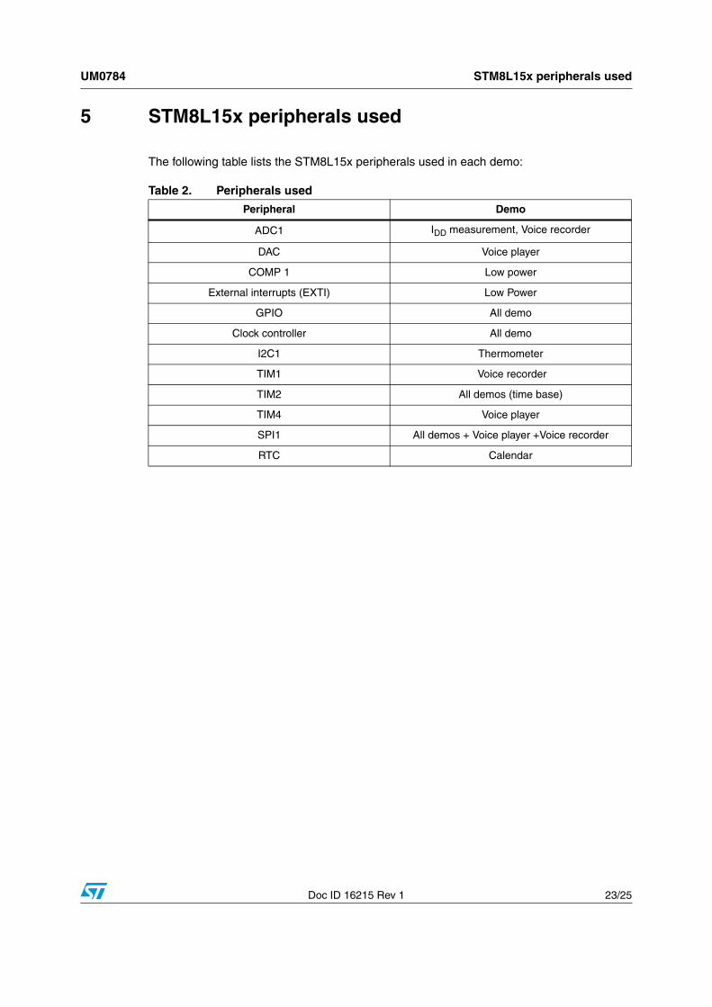
The following table lists the STM8L15x peripherals used in each demo:
Table 2. Peripherals used
Peripheral Demo
ADC1 IDD measurement, Voice recorder
DAC Voice player
COMP 1 Low power
External interrupts (EXTI) Low Power
GPIO All demo
Clock controller All demo
I2C1 Thermometer
TIM1 Voice recorder
TIM2 All demos (time base)
TIM4 Voice player
SPI1 All demos + Voice player +Voice recorder
RTC Calendar
Revision history UM0784
24/25 Doc ID 16215 Rev 1
6 Revision history
Table 3. Document revision history
Date Revision Changes
11-Sep-2009 1 Initial release.
UM0784
Doc ID 16215 Rev 1 25/25
Please Read Carefully:
Information in this document is provided solely in connection with ST products. STMicroelectronics NV and its subsidiaries (“ST”) reserve theright to make changes, corrections, modifications or improvements, to this document, and the products and services described herein at anytime, without notice.
All ST products are sold pursuant to ST’s terms and conditions of sale.
Purchasers are solely responsible for the choice, selection and use of the ST products and services described herein, and ST assumes noliability whatsoever relating to the choice, selection or use of the ST products and services described herein.
No license, express or implied, by estoppel or otherwise, to any intellectual property rights is granted under this document. If any part of thisdocument refers to any third party products or services it shall not be deemed a license grant by ST for the use of such third party productsor services, or any intellectual property contained therein or considered as a warranty covering the use in any manner whatsoever of suchthird party products or services or any intellectual property contained therein.
UNLESS OTHERWISE SET FORTH IN ST’S TERMS AND CONDITIONS OF SALE ST DISCLAIMS ANY EXPRESS OR IMPLIEDWARRANTY WITH RESPECT TO THE USE AND/OR SALE OF ST PRODUCTS INCLUDING WITHOUT LIMITATION IMPLIEDWARRANTIES OF MERCHANTABILITY, FITNESS FOR A PARTICULAR PURPOSE (AND THEIR EQUIVALENTS UNDER THE LAWSOF ANY JURISDICTION), OR INFRINGEMENT OF ANY PATENT, COPYRIGHT OR OTHER INTELLECTUAL PROPERTY RIGHT.
UNLESS EXPRESSLY APPROVED IN WRITING BY AN AUTHORIZED ST REPRESENTATIVE, ST PRODUCTS ARE NOTRECOMMENDED, AUTHORIZED OR WARRANTED FOR USE IN MILITARY, AIR CRAFT, SPACE, LIFE SAVING, OR LIFE SUSTAININGAPPLICATIONS, NOR IN PRODUCTS OR SYSTEMS WHERE FAILURE OR MALFUNCTION MAY RESULT IN PERSONAL INJURY,DEATH, OR SEVERE PROPERTY OR ENVIRONMENTAL DAMAGE. ST PRODUCTS WHICH ARE NOT SPECIFIED AS "AUTOMOTIVEGRADE" MAY ONLY BE USED IN AUTOMOTIVE APPLICATIONS AT USER’S OWN RISK.
Resale of ST products with provisions different from the statements and/or technical features set forth in this document shall immediately voidany warranty granted by ST for the ST product or service described herein and shall not create or extend in any manner whatsoever, anyliability of ST.
ST and the ST logo are trademarks or registered trademarks of ST in various countries.
Information in this document supersedes and replaces all information previously supplied.
The ST logo is a registered trademark of STMicroelectronics. All other names are the property of their respective owners.
© 2009 STMicroelectronics - All rights reserved
STMicroelectronics group of companies
Australia - Belgium - Brazil - Canada - China - Czech Republic - Finland - France - Germany - Hong Kong - India - Israel - Italy - Japan - Malaysia - Malta - Morocco - Philippines - Singapore - Spain - Sweden - Switzerland - United Kingdom - United States of America
www.st.com