WIRELESS SENSOR POSITIONING WITH ULTRAWIDEBAND FINGERPRINTING

Ultrawideband Log-periodic Series-fed Printed Dipole ArraysAntenna
Chittawan Choeysakul, Sarawuth Chaimool, and Prayoot AkkaraekthalinElectrical Engineering, Faculty of Engineering, King Mongkut’s Institute of Technology North Bangkok,
Bangkok 10800, Thailand, E-mail: [email protected]
AbstractBy replacing a printed dipole of quasi-Yagi antenna by a series-fed printed dipole arrays with planar trape-
zoidal toothed log-periodic structure, a new ultrawideband operation and end-fire radiation pattern are presented.The experiment results of the proposed antenna, determined from 10-dB return loss, larger than 121% of thecenter frequency that covers the ultrawideband applications band and end-fire radiation pattern.
1. IntroductionThe microstrip quasi-Yagi antenna exhibits attractive features including low profile, low-cost, light-
weight,ease of fabrication, and broadband operation. These features make the microstrip quasi-Yagi antenna at-tractive for use in various applications. An end-fire quasi-Yagi antenna which is broadband uniplanar structure hasbeen proposed for the first time by Kaneda et al.[1], achieving bandwidth 48% and since then explored in severalpapers[2]-[3]. Several bandwidth-enhancement techniques for printed dipoles or quasi-Yagi have been proposedin the literature, replacing printed dipole driver by printed bow-tie[4], patches driver [5] and a log-periodic dipolearrays director [6], tiled dipole [7] and several director elements [8]. However, those antennas have impedancebandwidths generally less than 85% of the center frequency.
In this paper, the printed dipole of quasi-Yagi antenna as driver and director is replaced by a series-fed printeddipole arrays with planar trapezoidal toothed log-periodic structure, which results in an improvement in bandwidthand gain. This new design combines a series-fed printed dipole arrays [9] and planar trapezoidal toothed log-periodic structure [10].
2. Antenna DesignFig. 1 shows the ultrawideband log-periodic series-fed printed dipole arrays antenna. The top metallization
consists of three parts, the microstrip-to-CPS transition, the series-fed printed-dipole arrays, and planar trapezoidaltoothed log-periodic structure. The truncated microstrip ground plane on backside of the substrate is used as areflector element for the antenna. We explain the three parts separately in order to understand the ultrawidebandcharacteristics of the antenna. Optimizing those three parts separately makes the optimization easier.
2. 1 Microstrip-to-CPS balunCoplanar strip (CPS) is a uniplanar transmission line and a microstrip balun is usually desired to provide
efficient transition between the CPS and the microstrip lines. The balun is used to introduce a half-wavelength
Figure 1: Schematic of the ultrawideband log-periodic series-fed printed dipole arrays antenna
Proceedings of ISAP2007, Niigata, Japan
ISBN: 978-4-88552-223-9 C3055©IEICE 25
1A4-1
(a) (b) (c)
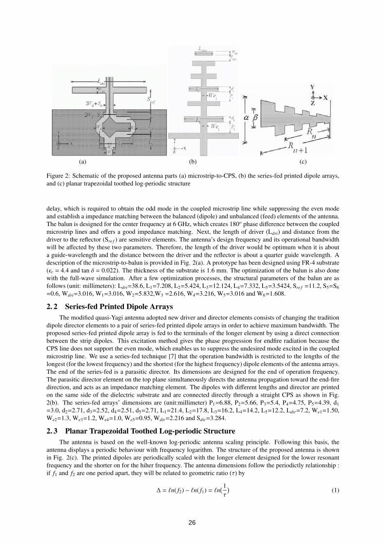
Figure 2: Schematic of the proposed antenna parts (a) microstrip-to-CPS, (b) the series-fed printed dipole arrays,and (c) planar trapezoidal toothed log-periodic structure
delay, which is required to obtain the odd mode in the coupled microstrip line while suppressing the even modeand establish a impedance matching between the balanced (dipole) and unbalanced (feed) elements of the antenna.The balun is designed for the center frequency at 6 GHz, which creates 180o phase difference between the coupledmicrostrip lines and offers a good impedance matching. Next, the length of driver (Ldri) and distance from thedriver to the reflector (Sre f ) are sensitive elements. The antenna’s design frequency and its operational bandwidthwill be affected by these two parameters. Therefore, the length of the driver would be optimum when it is abouta guide-wavelength and the distance between the driver and the reflector is about a quarter guide wavelength. Adescription of the microstrip-to-balun is provided in Fig. 2(a). A prototype has been designed using FR-4 substrate(εr = 4.4 and tan δ = 0.022). The thickness of the substrate is 1.6 mm. The optimization of the balun is also donewith the full-wave simulation. After a few optimization processes, the structural parameters of the balun are asfollows (unit: millimeters): Ldri=38.6, L1=7.208, L2=5.424, L3=12.124, L4=7.332, L5=3.5424, Sre f =11.2, S5=S6=0.6, Wdri=3.016, W1=3.016, W2=5.832,W3 =2.616, W4=3.216, W5=3.016 and W6=1.608.
2. 2 Series-fed Printed Dipole ArraysThe modified quasi-Yagi antenna adopted new driver and director elements consists of changing the tradition
dipole director elements to a pair of series-fed printed dipole arrays in order to achieve maximum bandwidth. Theproposed series-fed printed dipole array is fed to the terminals of the longer element by using a direct connectionbetween the strip dipoles. This excitation method gives the phase progression for endfire radiation because theCPS line does not support the even mode, which enables us to suppress the undesired mode excited in the coupledmicrostrip line. We use a series-fed technique [7] that the operation bandwidth is restricted to the lengths of thelongest (for the lowest frequency) and the shortest (for the highest frequency) dipole elements of the antenna arrays.The end of the series-fed is a parasitic director. Its dimensions are designed for the end of operation frequency.The parasitic director element on the top plane simultaneously directs the antenna propagation toward the end-firedirection, and acts as an impedance matching element. The dipoles with different lengths and director are printedon the same side of the dielectric substrate and are connected directly through a straight CPS as shown in Fig.2(b). The series-fed arrays’ dimensions are (unit:millimeter) P1=6.88, P2=5.66, P3=5.4, P4=4.75, P5=4.39, d1=3.0, d2=2.71, d3=2.52, d4=2.51, d5=2.71, L1=21.4, L2=17.8, L3=16.2, L4=14.2, L5=12.2, Ldir=7.2, We1=1.50,We2=1.3, We3=1.2, We4=1.0, We5=0.95, Wdir=2.216 and Sdir=3.284.
2. 3 Planar Trapezoidal Toothed Log-periodic StructureThe antenna is based on the well-known log-periodic antenna scaling principle. Following this basis, the
antenna displays a periodic behaviour with frequency logarithm. The structure of the proposed antenna is shownin Fig. 2(c). The printed dipoles are periodically scaled with the longer element designed for the lower resonantfrequency and the shorter on for the hiher frequency. The antenna dimensions follow the periodictly relationship :if f1 and f2 are one period apart, they will be related to geometric ratio (τ) by
∆ = `n( f2) − `n( f1) = `n(1τ
)(1)
26
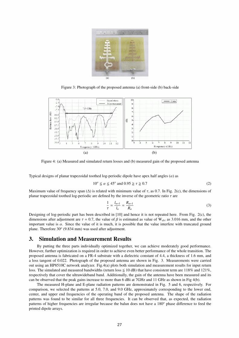
Figure 3: Photograph of the proposed antenna (a) front-side (b) back-side
(a) (b)
Figure 4: (a) Measured and simulated return losses and (b) measured gain of the proposed antenna
Typical designs of planar trapezoidal toothed log-periodic dipole have apex half angles (α) as
10o <= α <= 45o and 0.95 >= τ >= 0.7 (2)
Maximum value of frequency span (∆) is related with minimum value of τ, as 0.7. In Fig. 2(c), the dimensions ofplanar trapezoidal toothed log-periodic are defined by the inverse of the geometric ratio τ are
1τ
=ln+1
ln=
Rn+1
Rn(3)
Designing of log-periodic part has been described in [10] and hence it is not repeated here. From Fig. 2(c), thedimensions after adjustment are τ = 0.7, the value of β is estimated as value of Wdri as 3.016 mm, and the otherimportant value is α. Since the value of it is much, it is possible that the value interfere with truncated groundplane. Therefore 30o (9.834 mm) was used after adjustment.
3. Simulation and Measurement ResultsBy putting the three parts individually optimized together, we can achieve moderately good performance.
However, further optimization is required in order to achieve even better performance of the whole transition. Theproposed antenna is fabricated on a FR-4 substrate with a dielectric constant of 4.4, a thickness of 1.6 mm, anda loss tangent of 0.022. Photograph of the proposed antenna are shown in Fig. 3. Measurements were carriedout using an HP8510C network analyzer. Fig.4(a) plots both simulation and measurement results for input returnloss. The simulated and measured bandwidths (return loss <= 10 dB) that have consistent term are 118% and 121%,respectively that cover the ultrawideband band. Additionally, the gain of the antenna have been measured and itscan be observed that the peak gains increase to more than 6 dBi at 7GHz and 11 GHz as shown in Fig 4(b).
The measured H-plane and E-plane radiation patterns are demonstrated in Fig. 5 and 6, respectively. Forcomparison, we selected the patterns at 5.0, 7.0, and 9.0 GHz, approximately corresponding to the lower end,center, and upper end frequencies of the operating band of the proposed antenna. The shape of the radiationpatterns was found to be similar for all three frequencies. It can be observed that, as expected, the radiationpatterns of higher frequencies are irregular because the balun does not have a 180o phase difference to feed theprinted dipole arrays.
27

Figure 5: Measured the H-plane co- and cross-polarized radiation pattern of the proposed antenna (a) 5 GHz, (b) 7GHz, and (c) 9 GHz
Figure 6: Measured the E-plane co- and cross-polarized radiation pattern of the proposed antenna (a) 5 GHz, (b) 7GHz, and (c) 9 GHz
4. ConclusionThe ultrawideband log-periodic series-fed printed dipole arrays antenna has been proposed. The simulated and
measured results from the dsigned antenna has been obtained. This new structure exhibits about 121% impedancebandwidth that covers the ultrawideband applications band. The radiation charecteristics of proposed antenna havealso mesured at the selected frequencies, which represent the end-fire radiation pattern with a gain of about 3-7dBi. Becuase of its ultrawideband operation, low cost, easy fabrication, and good radition patterns, the proposedantenna should be very useful in the ultrawideband communication systems.
References[1] N. Kaneda, J. Sor, Y. Qian, and T.Itoh, “A novel Yagi-uda dipole array fed by a microstrip-to CPS transistion,” Asia Pacific
Microwave Conf. Dig., pp. 1413-1416, Yokohama, Japan, Dec. 1998.
[2] W. R. Deal, N. Kaneda, J. Sor, Y. Qian, and T.Itoh, “A new quasi-Yagi antenna for planar active antenna arrays,” IEEETrans. Antennas Propag., vol. 48, no. 6, pp. 910-918, June. 2000.
[3] N. Kaneda et al., “A Broadband Microstrip-to-Waveguide Transition Using Quasi-Yagi Antenna” IEEE Trans. MicrowaveTheory Tech., Vol.47 ,No. 12, Dec.1999, pp 2562-2567.
[4] A. A. Eldek, A. Z. Elsherbeni, and C. E. Smith, “Wideband microstrip-fed printed bow-tie antenna for phased-arraysystems,” Microwave Opt Technol Lett, vol. 43, no. 2, pp. 123-126, Oct. 2004.
[5] L. C. Kretly and C. E. Capovilla, “Patches driver on the quasi-Yagi antenna: analyses of bandwidth and radiation pattern,”IEEE Trans. Microwave Theory Tech., pp. 313-316, 2003.
[6] C. Choeysakul, S. Chaimool, and P. Akkaraekthalin, “A new quasi-Yagi antenna with a log-periodic dipole array director,”ECTI Conf., pp. 753-756. June 2006.
[7] L. C. Kretly and A. S. Ribeiro, “A novel tilted dipole quasi-Yagi antenna designed for 3G and blue-tooth applications,”IEEE Trans. Microwave Theory Tech., pp. 303-306, 2003.
[8] C. Ha, Y. Qian, and T. Itoh, “A modified quasi-Yagi planar antenna with wideband characteristics in C-band,” IEEE Proc.Antennas and Propagate., pp. 154-157, Jul. 2001.
[9] S.-G. Mao and S.-L. Chen, “Broadband Series-Fed Printed Dipole Arrays in Uniplanar Configulation,” URSI EMTS,pp.960-962, 2004.
[10] C. A. Balanis, Antenna Theory, 3rd Edition, John Wiley and Sons, New Jersy, 2005.
28