UltraView PTZ Installation Manual - surveillance-video.com · UltraView PTZ Installation Manual iv...
68
UltraView PTZ Installation Manual
Transcript of UltraView PTZ Installation Manual - surveillance-video.com · UltraView PTZ Installation Manual iv...
UltraView PTZ
Installation Manual
Copyright Copyright © 2011 UTC Fire & Security. All rights reserved.
This document may not be copied or otherwise reproduced, in whole or in part, except as specifically permitted under US and international copyright law, without the prior written consent from UTC Fire & Security.
Document number: 1069678B-EN (February 2011)
Disclaimer THE INFORMATION IN THIS DOCUMENT IS SUBJECT TO CHANGE WITHOUT NOTICE. UTC FIRE AND SECURITY ASSUMES NO RESPONSIBILITY FOR INACCURACIES OR OMISSIONS AND SPECIFICALLY DISCLAIMS ANY LIABILITIES, LOSSES, OR RISKS, PERSONAL OR OTHERWISE, INCURRED AS A CONSEQUENCE, DIRECTLY OR INDIRECTLY, OF THE USE OR APPLICATION OF ANY OF THE CONTENTS OF THIS DOCUMENT. FOR THE LATEST DOCUMENTATION, CONTACT YOUR LOCAL SUPPLIER OR VISIT US ONLINE AT WWW.INTERLOGIX.COM.
This publication may contain examples of screen captures and reports used in daily operations. Examples may include fictitious names of individuals and companies. Any similarity to names and addresses of actual businesses or persons is entirely coincidental.
Trademarks andpatents
UltraView name and logo are trademarks of UTC Fire & Security.
Interlogix is a trademark of UTC Fire & Security.
UltraView PTZ is a trademark of UTC Fire & Security.
Other trade names used in this document may be trademarks or registered trademarks of the manufacturers or vendors of the respective products.
Software licenseagreement
IImportant: This end-user license agreement (“Agreement”) is a legal agreement between UTC Fire & Security and You. Read the following terms and conditions carefully before installing or using this Software. This agreement provides a license from UTC Fire & Security to use the Software. It also contains warranty information, disclaimers, and liability limitations. Installing and/or using the Software confirms Your agreement to be bound by these terms and conditions. If You do not agree with these terms and conditions, do not install or use the Software or, if already installed, immediately cease all use of the Software and promptly uninstall all components of the Software.
Definitions. The following definitions apply to this document:
a. “UTC Fire & Security”, with respect to title to or warranty of the Software, means UTC Fire & Security Americas Corporation, Inc.
b. “Software” means SymNav, the executable software or firmware programs and accompanying documentation installed on the Interlogix products, plus any upgrades, modified versions, updates, additions, and copies of the software furnished to Customer during the term of the license granted herein.
c. “Documentation” means all associated media, printed materials, and electronic documentation accompanying the Software.
d. “Licensed Product” means the Software and Documentation.
e. “Customer” means the person or organization, or parent or subsidiary thereof, who uses the Software for its intended purposes, and excludes distributors, authorized resellers, value-added resellers and original equipment manufacturers. Customer may be referred to as You or Your, whether an individual or a business entity of any kind.
f. “Machine” means the computer, workstation, terminal, or other hardware product on which the Software is installed.
License. All rights to and in the Licensed Product, including, but not limited to, copyrights, patents, trademarks, and trade secrets, belong to UTC Fire & Security, and UTC Fire & Security retains title to each copy of the Software. You agree that UTC Fire & Security at any time, upon reasonable notice, may audit Your use of the Software for compliance with the terms and conditions of this Agreement. Subject to the terms and conditions of this Agreement, UTC Fire & Security grants You a nonexclusive license to use the Software, but only in the country where acquired, provided that You agree to the following:
iii
You may:
g. install and use the Software on a single Machine at one time, unless You have purchased additional copies of the Software, in which case You may install the soft-ware on the number of Machines for which You have purchased copies of the Soft-ware;
h. use the original copy of the Software provided to You for backup purposes.
You may not:
a. transfer or distribute the Licensed Product to others, in electronic format or otherwise, and this Agreement shall automatically terminate in the event of such a transfer or distribution;
b. use the Software over a computer network;
c. sell, rent, lease, or sublicense the Software;
d. copy or modify the Licensed Product for any purpose, including for backup purposes.
Term. This Agreement is effective until terminated. You may terminate this Agreement by uninstalling all components of the Software from all Machines and returning the Software to UTC Fire & Security. UTC Fire & Security may terminate this Agreement if You breach any of these terms and conditions. Upon termination of this Agreement for any reason, You agree to uninstall all components of the Software and return the Licensed Product to UTC Fire & Security. All provisions of this Agreement relating to (i) disclaimer of warranties; (ii) limitations on liability, remedies, and damages; and (iii) UTC Fire & Security’s proprietary rights, shall survive termination of this Agreement.
Object code. The Software is delivered in object code only. You may not alter, merge, modify, adapt, or translate the Software, nor decompile, disassemble, reverse-engineer, or otherwise reduce the Software to a human-perceivable form, nor create derivative works or programs based on the Software.
Limited warranty. UTC Fire & Security warrants that for one (1) year from the date of delivery of the Licensed Product (Software Warranty Period), the functions contained in the Software will be fit for their intended purpose as described in the applicable Documentation from UTC Fire & Security, and will conform in all material respects to the specifications stated in such Documentation. UTC Fire & Security does not warrant that the operation of the Software will be uninterrupted or error-free. UTC Fire & Security does warrant that the media on which the Software is furnished will be free from defects in materials and workmanship under normal use for a period of thirty (30) days from the date of delivery (Media Warranty Period). Except as specifically provided therein, any other software and any hardware furnished with or accompanying the Software is not warranted by UTC Fire & Security.
Your exclusive remedy under this limited warranty for nonconforming Software shall be repair or replacement of the Software, at the sole discretion of UTC Fire & Security. To obtain a repair or replacement of nonconforming Software, contact UTC Fire & Security Customer Service toll-free at 888-437-3287 or online at www.interlogix.com during the Software Warranty Period.
Except as expressly provided above, the licensed product is provided “as is” without warranty of any kind, either expressed or implied, including, but not limited to, implied warranties of merchantability or fitness for a particular purpose and, except as expressly provided above, You assume the entire risk as to the quality and performance of the licensed product.
Limitation of liability. UTC Fire & Security’s sole obligation or liability under this agreement is the repair or replacement of nonconforming software and/or defective media according to the limited warranty above. In no event will UTC Fire & Security be liable for damages, whether consequential, incidental, or indirect, nor for loss of data, loss of profits, or lost savings, arising from use or inability to use the software or documentation (or any hardware furnished with the software), even if UTC Fire & Security has been advised of the possibility of such damages, nor for any claim by any third party.
UltraView PTZInstallation Manual
iv
General. Any materials provided to You by UTC Fire & Security shall not be exported or reexported in violation of any export provisions of the USA or any other applicable jurisdiction. Any attempt to sublicense, assign, or transfer any of the rights, duties, or obligations hereunder shall be void. This Agreement shall be governed by and interpreted under the laws of the State of New York, United States of America, without regard to conflicts of law provisions. You hereby consent to the exclusive jurisdiction of the state and federal courts located in Multnomah County, Oregon, to resolve any disputes arising under or in connection with this Agreement, with venue in Portland, Oregon.
Restricted rights legend. The Licensed Product is provided with RESTRICTED RIGHTS. In the event the United States Government or an agency thereof is granted a license, the following additional terms apply: Restricted Computer Software, as defined in the Commercial Computer Software–Restricted Rights clause at Federal Acquisition Regulations 52.227-19, and the restrictions as provided in subparagraphs (c)(1) and (c)(2) thereof; and as applicable, the Government’s rights to use, modify, reproduce, release, perform, display, or disclose the Software also are restricted as provided by paragraphs (b)(2) and (b)(3) of the Rights in Noncommercial Technical Data and Computer Software–Small Business Innovative Research (SBIR) Program clause at DFARS 252.227-7018.
Acknowledgment. You acknowledge that You have read and understand this agreement and agree to be bound by its terms. You further agree that this agreement is the complete and exclusive statement of the agreement between You and UTC Fire & Security, and supersedes any proposal or prior agreement, oral or written, and any other communication relating to the subject matter of this agreement.
Intended use Use this product only for the purpose it was designed for; refer to the data sheet and user documentation. For the latest product information, contact your local supplier or visit us online at www.interlogix.com.
Manufacturer UTC Fire & Security Americas Corporation, Inc.
2955 Red Hill Ave, Costa Mesa, CA 92626, USA
Certification N4131
FCC compliance This equipment has been tested and found to comply with the limits for a Class A digital device, pursuant to part 15 of the FCC Rules. These limits are designed to provide reasonable protection against harmful interference when the equipment is operated in a commercial environment. This equipment generates, uses, and can radiate radio frequency energy and, if not installed and used in accordance with the instruction manual, may cause harmful interference to radio communications.
Changes or modifications not expressly approved by the party responsible for compliance could void the user’s authority to operate the equipment.
ACMA compliance Notice! This is a Class A product. In a domestic environment this product may cause radio interference in which case the user may be required to take adequate measures.
Canada This Class A digital apparatus complies with Canadian ICES-003.
Cet appareil numérique de la classe A est conforme à la norme NMB-003 du Canada.
EU Directives 2004/108/EC (EMC Directive). Non-European manufacturers must designate an authorized representative in the Community. Our authorized manufacturing representative is UTC Fire & Security, Kelvinstraat 7, 6003 DH Weert, Nederland.
2004/108/EC (EMC Directive): Hereby, UTC Fire & Security declares that this device is in compliance with the essential requirements and other relevant provisions of Directive 2004/108/EC.

v
2002/96/EC (WEEE directive). Products marked with this symbol cannot be disposed of as unsorted municipal waste in the European Union. For proper recycling, return this product to your local supplier upon the purchase of equivalent new equipment, or dispose of it at designated collection points. For more information, visit www.recyclethis.info.
Contact information For contact information, see www.interlogix.com.

UltraView PTZInstallation Manual
vi

vii
Contents
Preface. . . . . . . . . . . . . . . . . . . . . . . . . . . . . . . . . . . . . . . . . . . . . . . . . . . . . . . . . . . . . . . . . . ixConventions used in this document. . . . . . . . . . . . . . . . . . . . . . . . . . . . . . . . . . . . . . . . . . . . . ix
Safety terms and symbols . . . . . . . . . . . . . . . . . . . . . . . . . . . . . . . . . . . . . . . . . . . . . . . . . . . . . ix
Chapter 1. Introduction . . . . . . . . . . . . . . . . . . . . . . . . . . . . . . . . . . . . . . . . . . . . . . . . . . 1
Product overview . . . . . . . . . . . . . . . . . . . . . . . . . . . . . . . . . . . . . . . . . . . . . . . . . . . . . . . . . . 2Product contents . . . . . . . . . . . . . . . . . . . . . . . . . . . . . . . . . . . . . . . . . . . . . . . . . . . . . . . . . . . . . 2
System requirements . . . . . . . . . . . . . . . . . . . . . . . . . . . . . . . . . . . . . . . . . . . . . . . . . . . . . . . 3Operational requirements . . . . . . . . . . . . . . . . . . . . . . . . . . . . . . . . . . . . . . . . . . . . . . . . . . . . . . 3
Minimum load requirements . . . . . . . . . . . . . . . . . . . . . . . . . . . . . . . . . . . . . . . . . . . . . . . . . . . . 4
Power requirements . . . . . . . . . . . . . . . . . . . . . . . . . . . . . . . . . . . . . . . . . . . . . . . . . . . . . . . . . . . 5
Cable management. . . . . . . . . . . . . . . . . . . . . . . . . . . . . . . . . . . . . . . . . . . . . . . . . . . . . . . . . . . . 5
Cable requirements . . . . . . . . . . . . . . . . . . . . . . . . . . . . . . . . . . . . . . . . . . . . . . . . . . . . . . . . . . . 6
Power cable size and length requirements . . . . . . . . . . . . . . . . . . . . . . . . . . . . . . . . . . . . . . . . 7
Chapter 2. Housings and cables . . . . . . . . . . . . . . . . . . . . . . . . . . . . . . . . . . . . . . . . . . 9
Backward compatibility with CyberDome I housings . . . . . . . . . . . . . . . . . . . . . . . . . . . . 10
Various mounting and housing styles . . . . . . . . . . . . . . . . . . . . . . . . . . . . . . . . . . . . . . . . 10
Wiring best practices . . . . . . . . . . . . . . . . . . . . . . . . . . . . . . . . . . . . . . . . . . . . . . . . . . . . . . 12Pendant-mount wire routing . . . . . . . . . . . . . . . . . . . . . . . . . . . . . . . . . . . . . . . . . . . . . . . . . . . 12
Flush-mount wire routing . . . . . . . . . . . . . . . . . . . . . . . . . . . . . . . . . . . . . . . . . . . . . . . . . . . . . 13
Pendant-mount housings . . . . . . . . . . . . . . . . . . . . . . . . . . . . . . . . . . . . . . . . . . . . . . . . . . 14Preparing the surface for pendant-mounts . . . . . . . . . . . . . . . . . . . . . . . . . . . . . . . . . . . . . . . 14
Installing the housing . . . . . . . . . . . . . . . . . . . . . . . . . . . . . . . . . . . . . . . . . . . . . . . . . . . . . . . . 14
Flush-mount housings. . . . . . . . . . . . . . . . . . . . . . . . . . . . . . . . . . . . . . . . . . . . . . . . . . . . . 16Preparing the surface for flush-mounts . . . . . . . . . . . . . . . . . . . . . . . . . . . . . . . . . . . . . . . . . . 16
Installing the housing . . . . . . . . . . . . . . . . . . . . . . . . . . . . . . . . . . . . . . . . . . . . . . . . . . . . . . . . 17
Fan installation . . . . . . . . . . . . . . . . . . . . . . . . . . . . . . . . . . . . . . . . . . . . . . . . . . . . . . . . . . . 19
Preparing the cables . . . . . . . . . . . . . . . . . . . . . . . . . . . . . . . . . . . . . . . . . . . . . . . . . . . . . . 20
Chapter 3. Wiring. . . . . . . . . . . . . . . . . . . . . . . . . . . . . . . . . . . . . . . . . . . . . . . . . . . . . . 21
Components used for basic and advanced operation . . . . . . . . . . . . . . . . . . . . . . . . . . . 22Alarm/contact connectors . . . . . . . . . . . . . . . . . . . . . . . . . . . . . . . . . . . . . . . . . . . . . . . . . . . . . 23
Wiring the housing board . . . . . . . . . . . . . . . . . . . . . . . . . . . . . . . . . . . . . . . . . . . . . . . . . . 24
Setting the termination . . . . . . . . . . . . . . . . . . . . . . . . . . . . . . . . . . . . . . . . . . . . . . . . . . . . 26
UltraView PTZInstallation Manual
viii
Chapter 4. Camera assembly, shroud, bubble dome. . . . . . . . . . . . . . . . . . . . . . . . . 27
Camera assembly preparation and installation. . . . . . . . . . . . . . . . . . . . . . . . . . . . . . . . . 28Setting the protocol . . . . . . . . . . . . . . . . . . . . . . . . . . . . . . . . . . . . . . . . . . . . . . . . . . . . . . . . . . 29
Setting the camera’s address . . . . . . . . . . . . . . . . . . . . . . . . . . . . . . . . . . . . . . . . . . . . . . . . . . 30
Installing the camera assembly . . . . . . . . . . . . . . . . . . . . . . . . . . . . . . . . . . . . . . . . . . . . . . . . 32
Shroud and bubble dome installation . . . . . . . . . . . . . . . . . . . . . . . . . . . . . . . . . . . . . . . . 32Installing a camera shroud . . . . . . . . . . . . . . . . . . . . . . . . . . . . . . . . . . . . . . . . . . . . . . . . . . . . 33
Installing a bubble dome . . . . . . . . . . . . . . . . . . . . . . . . . . . . . . . . . . . . . . . . . . . . . . . . . . . . . . 34
Chapter 5. Troubleshooting, maintenance, support . . . . . . . . . . . . . . . . . . . . . . . . . 37
Troubleshooting . . . . . . . . . . . . . . . . . . . . . . . . . . . . . . . . . . . . . . . . . . . . . . . . . . . . . . . . . . 38
Maintenance . . . . . . . . . . . . . . . . . . . . . . . . . . . . . . . . . . . . . . . . . . . . . . . . . . . . . . . . . . . . . 39Cleaning the bubble dome. . . . . . . . . . . . . . . . . . . . . . . . . . . . . . . . . . . . . . . . . . . . . . . . . . . . . 39
Contacting us . . . . . . . . . . . . . . . . . . . . . . . . . . . . . . . . . . . . . . . . . . . . . . . . . . . . . . . . . . . . 40Online . . . . . . . . . . . . . . . . . . . . . . . . . . . . . . . . . . . . . . . . . . . . . . . . . . . . . . . . . . . . . . . . . . . . . 40
. . . . . . . . . . . . . . . . . . . . . . . . . . . . . . . . . . . . . . . . . . . . . . . . . . . . . . . . . . . . . . . . . . . . . . . . . . . 40
GEA-102 wall-mount arm . . . . . . . . . . . . . . . . . . . . . . . . . . . . . . . . . . . . . . . . . . . . . . . . . . . 42Installing the wall-mount arm . . . . . . . . . . . . . . . . . . . . . . . . . . . . . . . . . . . . . . . . . . . . . . . . . . 42
Opening a conduit hole . . . . . . . . . . . . . . . . . . . . . . . . . . . . . . . . . . . . . . . . . . . . . . . . . . . . . . . 45
GEA-114 T-bar ceiling support kit. . . . . . . . . . . . . . . . . . . . . . . . . . . . . . . . . . . . . . . . . . . . 47Installing the T-bar ceiling support kit . . . . . . . . . . . . . . . . . . . . . . . . . . . . . . . . . . . . . . . . . . . 47
UltraView PTZ protocol functionality . . . . . . . . . . . . . . . . . . . . . . . . . . . . . . . . . . . . . . . . . 52
Equipment protocol testing list. . . . . . . . . . . . . . . . . . . . . . . . . . . . . . . . . . . . . . . . . . . . . . 56
ix
PrefaceThis is the Interlogix UltraView PTZ Installation Manual. This document includes an overview of the product and detailed instructions explaining:
• how to install the housing; and • how to attach the pan/tilt/zoom (PTZ) camera assembly.
There is also information describing how to contact technical support if you have questions or concerns.
To use this document effectively, you should have the following minimum qualifications:
• a basic knowledge of CCTV systems and components; and• a basic knowledge of electrical wiring and low-voltage electrical connections.
Read these instructions and all ancillary documentation entirely before installing or operating this product. The most current versions of this and related documentation may be found on our website at www.interlogix.com.
Note: A qualified service person, complying with all applicable codes, should perform all required hardware installation.
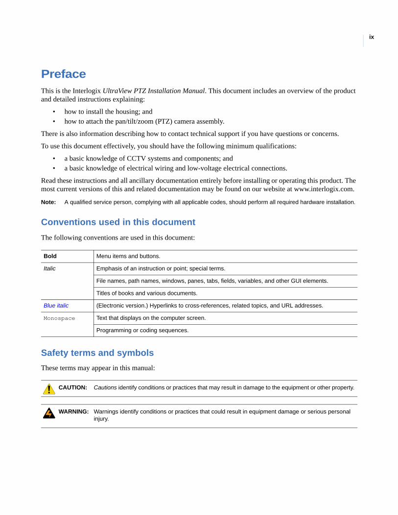
Conventions used in this document
The following conventions are used in this document:
Safety terms and symbols
These terms may appear in this manual:
Bold Menu items and buttons.
Italic Emphasis of an instruction or point; special terms.
File names, path names, windows, panes, tabs, fields, variables, and other GUI elements.
Titles of books and various documents.
Blue italic (Electronic version.) Hyperlinks to cross-references, related topics, and URL addresses.
Monospace Text that displays on the computer screen.
Programming or coding sequences.
CAUTION: Cautions identify conditions or practices that may result in damage to the equipment or other property.
WARNING: Warnings identify conditions or practices that could result in equipment damage or serious personal injury.

UltraView PTZInstallation Manual
x
This chapter provides an overview of your UltraView PTZ dome system, including product contents and system requirements.
In this chapter:
Product overview . . . . . . . . . . . . . . . . . . . . . . . . . . . . . . . . . . . . . . . . . . . .2Product contents . . . . . . . . . . . . . . . . . . . . . . . . . . . . . . . . . . . . . . . . .2
System requirements . . . . . . . . . . . . . . . . . . . . . . . . . . . . . . . . . . . . . . . . .3Operational requirements . . . . . . . . . . . . . . . . . . . . . . . . . . . . . . . . . .3Minimum load requirements . . . . . . . . . . . . . . . . . . . . . . . . . . . . . . . .4Cable management . . . . . . . . . . . . . . . . . . . . . . . . . . . . . . . . . . . . . . .5Cable requirements . . . . . . . . . . . . . . . . . . . . . . . . . . . . . . . . . . . . . . .6Power cable size and length requirements . . . . . . . . . . . . . . . . . . . . .7
Chapter 1 Introduction
UltraView PTZInstallation Manual
2
Product overviewUltraView PTZ ™ is a line of advanced pan/tilt/zoom (PTZ) cameras. In addition to powerful cameras, UltraView PTZ features a graphical programming interface for easier customization of camera settings, and passcodes for protection against unauthorized access.
The UltraView PTZ supports many protocols to work with various keypad controllers, digital video recorders, and other video surveillance equipment. (See Setting the protocol on page 27 for a list of supported protocols.)
Installation of the UltraView PTZ line of domes is simplified because all power, data, video, and alarm connections are provided in the housing. Configuration parameters such as presets and tours unique to each installation site are stored in the housing memory. This allows you to replace cameras or move them between housings without having to reprogram them for each new site. As you install the first dome, you will find many other enhancements that make installation easier and quicker.
The general steps for installing your dome include:
• preparing the mounting surface and installing the mount (if used) and housing;• preparing the cables and wiring the housing;• addressing the camera site, setting the protocol, and setting the termination;• installing the PTZ camera assembly; and• installing the dome.
Be aware that the power requirements for CyberDome and UltraView PTZ are different. See Power requirements on page 5 and Cable management on page 5.
Product contents
The UltraView PTZ consists of the following:
• Housing.• Package containing three connectors (one 2-pin for power; one 6-pin for UTP, auxiliary data, and
RS-485; one 14-pin for alarms and contacts) and a small screwdriver. (The Select version of UltraView PTZ has two connectors: a 2-pin connector for power and a 2-pin connector for RS-485 data.)
• PTZ camera assembly.• Dome (mirror domes are shipped with cotton gloves for special handling).• Mount (wall-mount and flush-mount versions only).• Installation and user manuals.
You may receive the package contents in one large carton containing three boxes (four with wall-mount versions), or if shipped individually, you may receive three (or four) separate boxes. One box will contain the housing, connectors, and manuals. The PTZ assembly, dome, and mount (for wall-mount versions) are each shipped in separate boxes.
Inspect the packages and contents for visible damage. If any components are damaged or missing, do not use the unit; contact the supplier immediately. If you need to return the unit, you must ship it in the original box.

Chapter 1Introduction
3
System requirementsFor proper operation, adhere to the following operational, load, cable, and power requirements for UltraView PTZ domes.
Operational requirements
UltraView PTZ contains a built-in receiver that decodes commands originating from a compatible controlling device, such as a keypad or ASCII control software. A minimum of one controlling device is required for operation, as shown in Figure 1. In this typical DVR system, an operator can pan, tilt, and zoom the camera, find presets, and start preset and ShadowTours from the keypad.
Figure 1. Typical DVR system
Figure 2 shows a typical network system, and Figure 3 on page 4 shows an enhanced system.
Figure 2. Typical IP system
SymDec 16 DVR(IP digital video recorder)
I/O box KTD-405A controller keypad
CCTV monitor
RS-485
Video
UltraView PTZ
RS-485
SymNetIP encoder/decoders
I/O box KTD-405A controller keypad
CCTV monitor
TCP/IP
Video
UltraView PTZ
UltraView PTZInstallation Manual
4
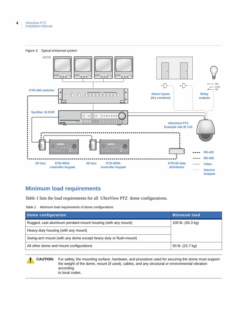
Figure 3. Typical enhanced system
Minimum load requirements
Table 1 lists the load requirements for all UltraView PTZ dome configurations.
Table 1. Minimum load requirements of dome configurations
Dome configuration Minimum load
Rugged, cast aluminum pendant-mount housing (with any mount) 100 lb. (45.3 kg)
Heavy-duty housing (with any mount)
Swing-arm mount (with any dome except heavy duty or flush-mount)
All other dome and mount configurations 50 lb. (22.7 kg)
CAUTION: For safety, the mounting surface, hardware, and procedure used for securing the dome must support the weight of the dome, mount (if used), cables, and any structural or environmental vibration according to local codes.
RS-485
VideoI/O box KTD-405A controller keypad
Alarms/Outputs
CCTV
I/O box KTD-405A controller keypad
SymDec 16 DVR
KTD-83 data distributor
UltraView PTZExample site ID #15
KTD-440 switcher
RS-422
Alarm inputs (dry contacts)
Relay outputs
Chapter 1Introduction
5
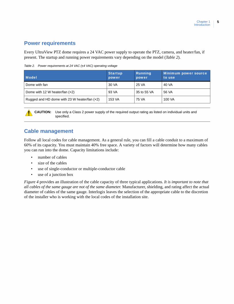
Power requirements
Every UltraView PTZ dome requires a 24 VAC power supply to operate the PTZ, camera, and heater/fan, if present. The startup and running power requirements vary depending on the model (Table 2).
Cable management
Follow all local codes for cable management. As a general rule, you can fill a cable conduit to a maximum of 60% of its capacity. You must maintain 40% free space. A variety of factors will determine how many cables you can run into the dome. Capacity limitations include:
• number of cables• size of the cables• use of single-conductor or multiple-conductor cable• use of a junction box
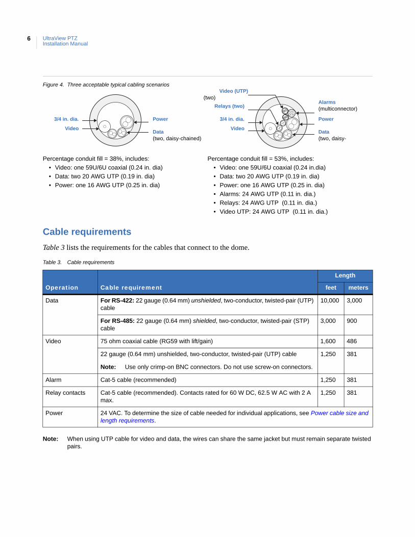
Figure 4 provides an illustration of the cable capacity of three typical applications. It is important to note that all cables of the same gauge are not of the same diameter. Manufacturer, shielding, and rating affect the actual diameter of cables of the same gauge. Interlogix leaves the selection of the appropriate cable to the discretion of the installer who is working with the local codes of the installation site.
Table 2. Power requirements at 24 VAC (±4 VAC) operating voltage
ModelStartup power
Running power
Minimum power source to use
Dome with fan 30 VA 25 VA 40 VA
Dome with 12 W heater/fan (×2) 93 VA 35 to 55 VA 56 VA
Rugged and HD dome with 23 W heater/fan (×2) 153 VA 75 VA 100 VA
CAUTION: Use only a Class 2 power supply of the required output rating as listed on individual units and specified.
UltraView PTZInstallation Manual
6
Figure 4. Three acceptable typical cabling scenarios
Cable requirements
Table 3 lists the requirements for the cables that connect to the dome.
Note: When using UTP cable for video and data, the wires can share the same jacket but must remain separate twisted pairs.
Percentage conduit fill = 38%, includes:
• Video: one 59U/6U coaxial (0.24 in. dia)
• Data: two 20 AWG UTP (0.19 in. dia)
• Power: one 16 AWG UTP (0.25 in. dia)
Percentage conduit fill = 53%, includes:
• Video: one 59U/6U coaxial (0.24 in.dia)
• Data: two 20 AWG UTP (0.19 in. dia)
• Power: one 16 AWG UTP (0.25 in. dia)
• Alarms: 24 AWG UTP (0.11 in. dia.)
• Relays: 24 AWG UTP (0.11 in. dia.)
• Video UTP: 24 AWG UTP (0.11 in. dia.)
Table 3. Cable requirements
Operation Cable requirement
Length
feet meters
Data For RS-422: 22 gauge (0.64 mm) unshielded, two-conductor, twisted-pair (UTP) cable
10,000 3,000
For RS-485: 22 gauge (0.64 mm) shielded, two-conductor, twisted-pair (STP) cable
3,000 900
Video 75 ohm coaxial cable (RG59 with lift/gain) 1,600 486
22 gauge (0.64 mm) unshielded, two-conductor, twisted-pair (UTP) cable
Note: Use only crimp-on BNC connectors. Do not use screw-on connectors.
1,250 381
Alarm Cat-5 cable (recommended) 1,250 381
Relay contacts Cat-5 cable (recommended). Contacts rated for 60 W DC, 62.5 W AC with 2 A max.
1,250 381
Power 24 VAC. To determine the size of cable needed for individual applications, see Power cable size and length requirements.
3/4 in. dia.
Video
Power
Relays (two)
Data(two, daisy-chained)
Alarms(multiconnector)
3/4 in. dia.
Video
Power
Data(two, daisy-
Video (UTP)(two)
Chapter 1Introduction
7
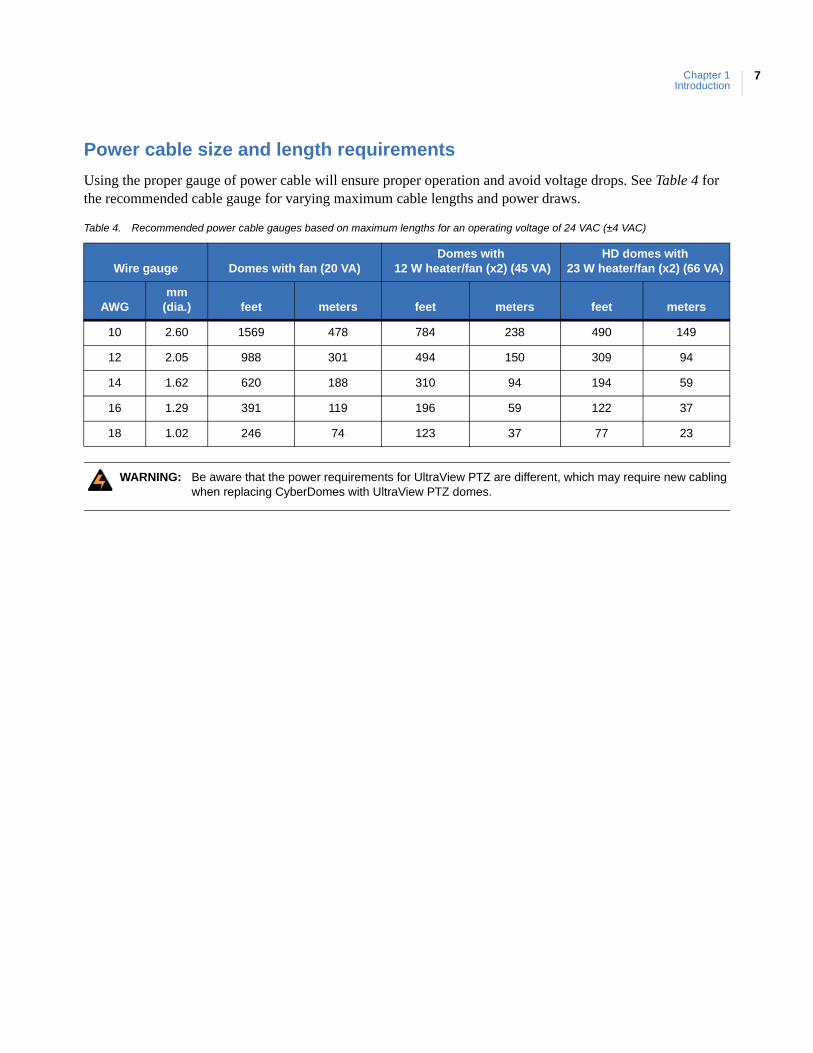
Power cable size and length requirements
Using the proper gauge of power cable will ensure proper operation and avoid voltage drops. See Table 4 for the recommended cable gauge for varying maximum cable lengths and power draws.
Table 4. Recommended power cable gauges based on maximum lengths for an operating voltage of 24 VAC (±4 VAC)
Wire gauge Domes with fan (20 VA)Domes with
12 W heater/fan (x2) (45 VA)HD domes with
23 W heater/fan (x2) (66 VA)
AWGmm
(dia.) feet meters feet meters feet meters
10 2.60 1569 478 784 238 490 149
12 2.05 988 301 494 150 309 94
14 1.62 620 188 310 94 194 59
16 1.29 391 119 196 59 122 37
18 1.02 246 74 123 37 77 23
WARNING: Be aware that the power requirements for UltraView PTZ are different, which may require new cabling when replacing CyberDomes with UltraView PTZ domes.

UltraView PTZInstallation Manual
8

This chapter provides instructions for installing housings and cables.
In this chapter:
Backward compatibility with CyberDome I housings . . . . . . . . . . . . . . .10Various mounting and housing styles . . . . . . . . . . . . . . . . . . . . . . . . . . .10Wiring best practices . . . . . . . . . . . . . . . . . . . . . . . . . . . . . . . . . . . . . . . .12
Pendant-mount wire routing . . . . . . . . . . . . . . . . . . . . . . . . . . . . . . .12Flush-mount wire routing . . . . . . . . . . . . . . . . . . . . . . . . . . . . . . . . .13
Pendant-mount housings . . . . . . . . . . . . . . . . . . . . . . . . . . . . . . . . . . . . .14Preparing the surface for pendant-mounts . . . . . . . . . . . . . . . . . . . .14Installing the housing . . . . . . . . . . . . . . . . . . . . . . . . . . . . . . . . . . . .14
Flush-mount housings . . . . . . . . . . . . . . . . . . . . . . . . . . . . . . . . . . . . . . .16Preparing the surface for flush-mounts . . . . . . . . . . . . . . . . . . . . . .16Installing the housing . . . . . . . . . . . . . . . . . . . . . . . . . . . . . . . . . . . .17
Fan installation . . . . . . . . . . . . . . . . . . . . . . . . . . . . . . . . . . . . . . . . . . . .19Preparing the cables . . . . . . . . . . . . . . . . . . . . . . . . . . . . . . . . . . . . . . . .20
Chapter 2 Housings and cables
UltraView PTZInstallation Manual
10
Backward compatibility with CyberDome I housingsThe UltraView PTZ is compatible with CyberDome I housings, but there are some exceptions. Although the onscreen display (OSD) interface, including menus, will show the UltraView PTZ design, not all of the UltraView PTZ features are supported on CyberDome I housings. The following features are not available:
• Site-tied memory• Internal alarms• Internal relays• Internal wiring terminal blocks• Advanced heater and fan system• Lift and gain functionality.• Up-the-coax (UTC) protocol support
Also, if you install an UltraView PTZ in an older CyberDome I housing, you must install a fan assembly on the tilt arm of the PTZ. (See Fan installation on page 19 for instructions.) You may use the fan from your CyberDome I PTZ, or call Customer Service (see Contacting us on page 38) to order a new one (part number 1046540).
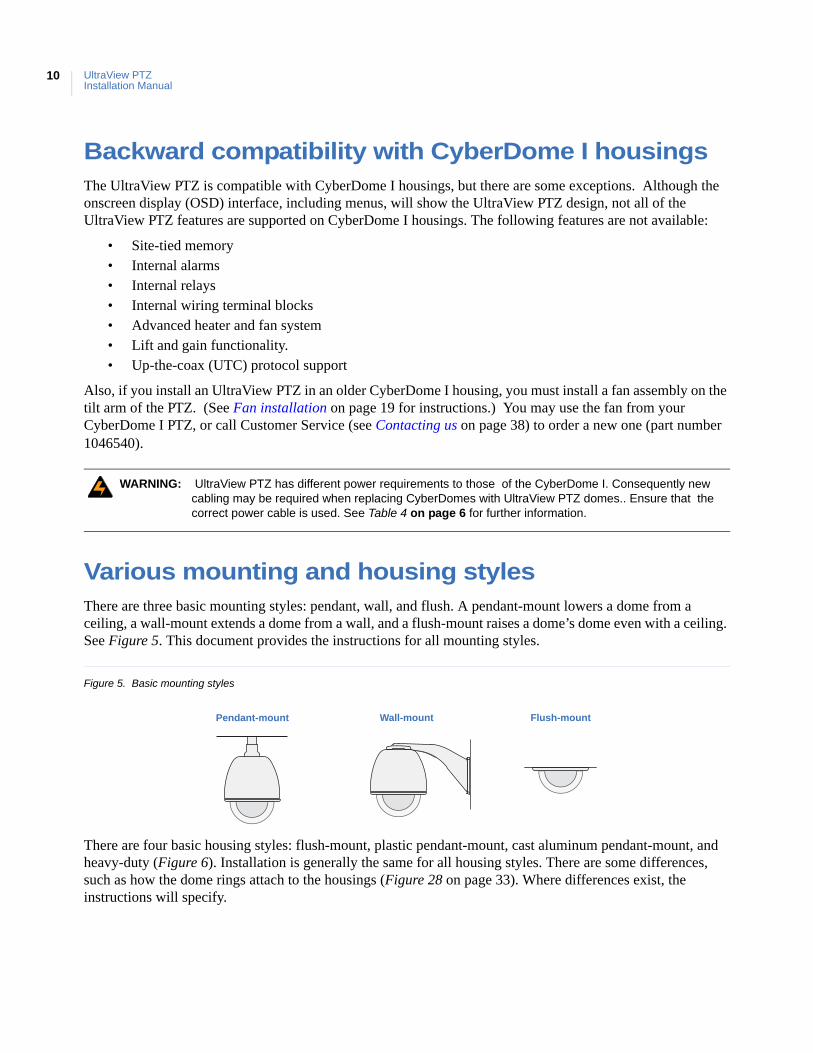
Various mounting and housing stylesThere are three basic mounting styles: pendant, wall, and flush. A pendant-mount lowers a dome from a ceiling, a wall-mount extends a dome from a wall, and a flush-mount raises a dome’s dome even with a ceiling. See Figure 5. This document provides the instructions for all mounting styles.
Figure 5. Basic mounting styles
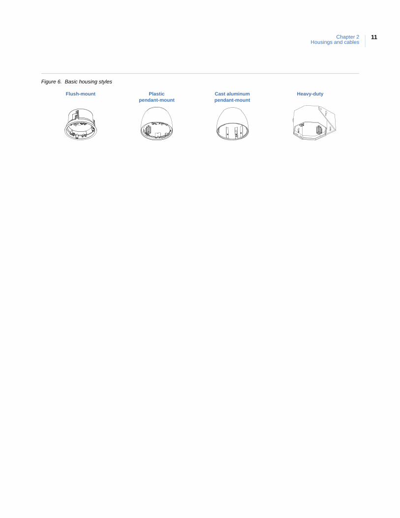
There are four basic housing styles: flush-mount, plastic pendant-mount, cast aluminum pendant-mount, and heavy-duty (Figure 6). Installation is generally the same for all housing styles. There are some differences, such as how the dome rings attach to the housings (Figure 28 on page 33). Where differences exist, the instructions will specify.
WARNING: UltraView PTZ has different power requirements to those of the CyberDome I. Consequently new cabling may be required when replacing CyberDomes with UltraView PTZ domes.. Ensure that the correct power cable is used. See Table 4 on page 6 for further information.
Pendant-mount Wall-mount Flush-mount
Chapter 2Housings and cables
11
Figure 6. Basic housing styles
Flush-mount Plasticpendant-mount
Cast aluminumpendant-mount
Heavy-duty
UltraView PTZInstallation Manual
12
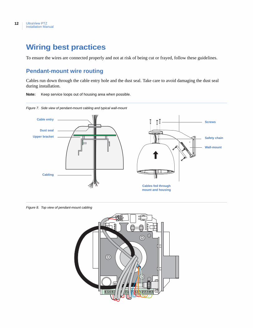
Wiring best practicesTo ensure the wires are connected properly and not at risk of being cut or frayed, follow these guidelines.
Pendant-mount wire routing
Cables run down through the cable entry hole and the dust seal. Take care to avoid damaging the dust seal during installation.
Note: Keep service loops out of housing area when possible.
Figure 7. Side view of pendant-mount cabling and typical wall-mount
Figure 8. Top view of pendant-mount cabling
Upper bracket
Dust seal
Cabling
Cable entry
Cables fed through mount and housing
Screws
Wall-mount
Safety chain
Chapter 2Housings and cables
13
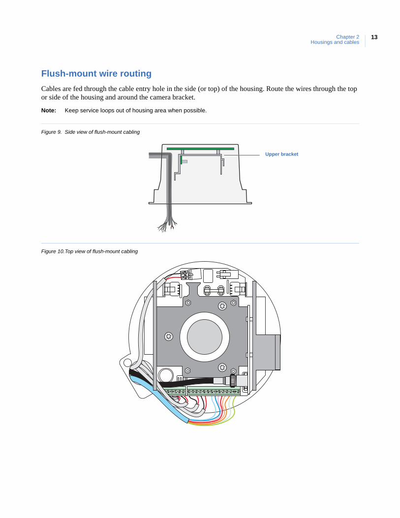
Flush-mount wire routing
Cables are fed through the cable entry hole in the side (or top) of the housing. Route the wires through the top or side of the housing and around the camera bracket.
Note: Keep service loops out of housing area when possible.
Figure 9. Side view of flush-mount cabling
Figure 10.Top view of flush-mount cabling
Upper bracket
UltraView PTZInstallation Manual
14
Pendant-mount housingsPendant-mount and flush-mount housings require different preparation of the mounting surface and different installation procedures of the housings. Follow the instructions given here for pendant-mount housings.
Pendant-mount housings can be mounted to a pipe to lower them from a ceiling or to a wall-mount arm to extend them from a wall. Instructions are provided in this document for both mounting methods.
Preparing the surface for pendant-mounts
Following are the steps for preparing the mounting surface if you are mounting the housing to a pipe. If you are mounting the housing to the GEA-102 wall-mount arm, instructions for installing the GEA-102 are available in this manual (Installing the wall-mount arm on page 40). If you are installing one of the other mounts, refer to the instructions that came with the mount.
To prepare the mounting surface:
1. Following all local codes, install the pipe.
2. Make sure that the facility cables (data, video, and power) for the dome comply with the recommendations provided in Cable requirements on page 6.
3. Feed the facility cables through the pipe in the mounting surface.
• Pull enough cable to make connections. You can always pull back unneeded length later. • How many cables you have depends upon how many video, data, and power cables. See Wiring on
page 19.
Installing the housing
With the pipe or mount now installed, install the housing.
If you are installing the housing outdoors and onto a pipe, you must install the rubber water-sealing boot that provides an additional layer of water protection. Applying PTFE thread sealing tape (for example, Teflon® tape) to the pipe is required as a first layer of protection.
CAUTION: For all installations, heed these cautions:
• Complete all installation steps before supplying power to the dome.
• To ensure proper operation of a PTZ unit, install the mount level.
• For safety, the mounting surface, hardware, and procedure used for securing the dome must support the weight of the dome, mount (if used), cables, and any structural or environmentalvibration according to local codes. See Table 1 on page 4.
CAUTION: Avoid getting rain or moisture in the housing so that the electronic components on the PCBs are not damaged.
Chapter 2Housings and cables
15
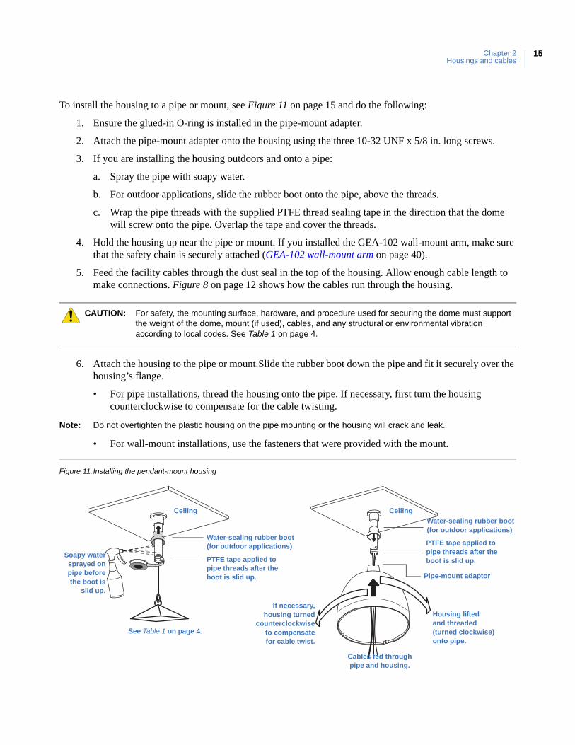
To install the housing to a pipe or mount, see Figure 11 on page 15 and do the following:
1. Ensure the glued-in O-ring is installed in the pipe-mount adapter.
2. Attach the pipe-mount adapter onto the housing using the three 10-32 UNF x 5/8 in. long screws.
3. If you are installing the housing outdoors and onto a pipe:
a. Spray the pipe with soapy water.
b. For outdoor applications, slide the rubber boot onto the pipe, above the threads.
c. Wrap the pipe threads with the supplied PTFE thread sealing tape in the direction that the dome will screw onto the pipe. Overlap the tape and cover the threads.
4. Hold the housing up near the pipe or mount. If you installed the GEA-102 wall-mount arm, make sure that the safety chain is securely attached (GEA-102 wall-mount arm on page 40).
5. Feed the facility cables through the dust seal in the top of the housing. Allow enough cable length to make connections. Figure 8 on page 12 shows how the cables run through the housing.
6. Attach the housing to the pipe or mount.Slide the rubber boot down the pipe and fit it securely over the housing’s flange.
• For pipe installations, thread the housing onto the pipe. If necessary, first turn the housing counterclockwise to compensate for the cable twisting.
Note: Do not overtighten the plastic housing on the pipe mounting or the housing will crack and leak.
• For wall-mount installations, use the fasteners that were provided with the mount.
Figure 11.Installing the pendant-mount housing
CAUTION: For safety, the mounting surface, hardware, and procedure used for securing the dome must support the weight of the dome, mount (if used), cables, and any structural or environmental vibration according to local codes. See Table 1 on page 4.
Ceiling
Housing liftedand threaded(turned clockwise)onto pipe.
If necessary,housing turned
counterclockwiseto compensatefor cable twist.
Cables fed throughpipe and housing.
See Table 1 on page 4.
Ceiling
Water-sealing rubber boot(for outdoor applications)
PTFE tape applied to pipe threads after the boot is slid up.
Soapy watersprayed onpipe before the boot is
slid up.
Water-sealing rubber boot(for outdoor applications)
PTFE tape applied to pipe threads after the boot is slid up.
Pipe-mount adaptor
UltraView PTZInstallation Manual
16
Flush-mount housingsFlush-mount and pendant-mount housings require different preparation of the mounting surface and different installation procedures of the housings. Follow the instructions given here for flush-mount housings.
Preparing the surface for flush-mounts
Following are the steps for preparing the mounting surface if you are mounting the housing directly into a solid surface that does not require reinforcement. If the mounting surface does require reinforcement, first install a GEA-113 T-bar ceiling panel or a GEA-114 T-bar support kit. Instructions for installing the GEA-114 are available in this manual (GEA-114 T-bar ceiling support kit on page 45). If you are installing a GEA-113, refer to the instructions that came with the panel (1052914).
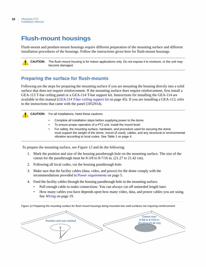
To prepare the mounting surface, see Figure 12 and do the following:
1. Mark the position and size of the housing passthrough hole on the mounting surface. The size of the cutout for the passthrough must be 8-3/8 to 8-7/16 in. (21.27 to 21.42 cm).
2. Following all local codes, cut the housing passthrough hole.
3. Make sure that the facility cables (data, video, and power) for the dome comply with the recommendations provided in Power requirements on page 5.
4. Feed the facility cables through the housing passthrough hole in the mounting surface. • Pull enough cable to make connections. You can always cut off unneeded length later. • How many cables you have depends upon how many video, data, and power cables you are using.
See Wiring on page 19.
Figure 12.Preparing the mounting surface for flush-mount housings being mounted into solid surfaces not requiring reinforcement
CAUTION: The flush-mount housing is for indoor applications only. Do not expose it to moisture, or the unit may become damaged.
CAUTION: For all installations, heed these cautions:
• Complete all installation steps before supplying power to the dome.
• To ensure proper operation of a PTZ unit, install the mount level.
• For safety, the mounting surface, hardware, and procedure used for securing the dome must support the weight of the dome, mount (if used), cables, and any structural or environmentalvibration according to local codes. See Table 1 on page 4.
Cutout size:8-3/8 to 8-7/16 in.
(21.27 to 21.42 cm)Position and size marked
Chapter 2Housings and cables
17
Installing the housing
With the surface prepared and/or the mount now installed, install the housing.
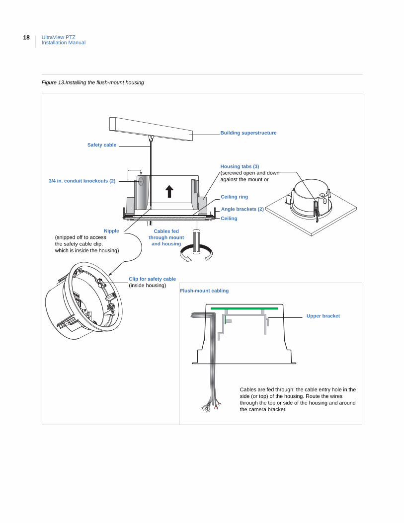
To install a flush-mount housing, see Figure 13 on page 18 and do the following:
1. Remove either conduit knockout (side or top) in the housing.
2. Hold the housing up near the housing passthrough of the mount or cutout.
3. Connect a steel safety cable, if required by local codes.
a. Obtain a steel safety cable of 0.125 in. (3 mm) maximum diameter that complies with local codes.
b. Snip off the nipple that opens access to the safety cable clip.
c. Feed your safety cable through the exposed hole.
d. Secure one end of the safety cable into the safety clip surrounding the exposed hole inside the housing.
e. Secure the other end of the safety cable to the building superstructure.
4. Feed the facility cables through the conduit hole of the housing. Allow enough cable length to make connections. Figure 9 on page 13 shows how the cables run through the housing.
5. Attach the housing to the mount or ceiling by screwing the housing tabs open and down.
CAUTION: All flush-mount installations must have a fan. If you are installing a flush-mount housing that does not have a fan, see Fan installation on page 19.
CAUTION: For safety, the mounting surface, hardware, and procedure used for securing the dome must support the weight of the dome, mount (if used), cables, and any structural or environmental vibration according to local codes. See Table 1 on page 4.
UltraView PTZInstallation Manual
18
Figure 13.Installing the flush-mount housing
Nipple(snipped off to accessthe safety cable clip,which is inside the housing)
3/4 in. conduit knockouts (2)
Cables fedthrough mount
and housing
Ceiling ring
Ceiling
Angle brackets (2)
Housing tabs (3)(screwed open and downagainst the mount or
Clip for safety cable(inside housing)
Safety cable
Building superstructure
Cables are fed through: the cable entry hole in the side (or top) of the housing. Route the wires through the top or side of the housing and around the camera bracket.
Upper bracket
Flush-mount cabling
Chapter 2Housings and cables
19
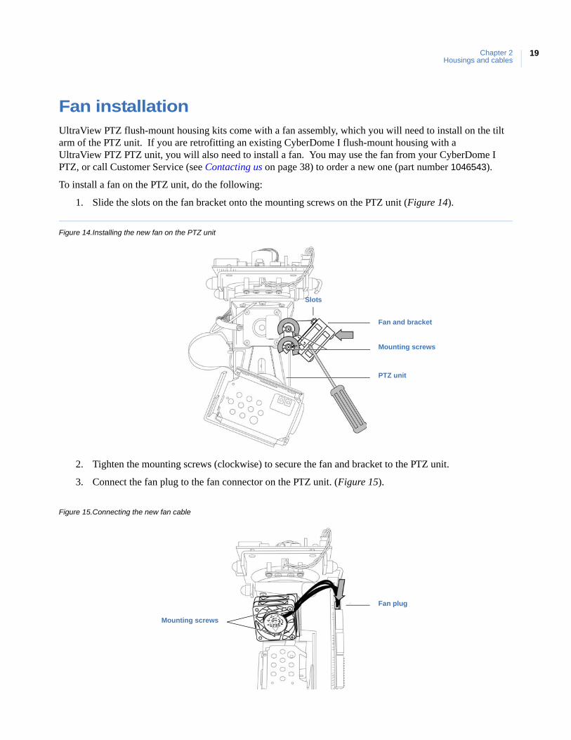
Fan installationUltraView PTZ flush-mount housing kits come with a fan assembly, which you will need to install on the tilt arm of the PTZ unit. If you are retrofitting an existing CyberDome I flush-mount housing with a UltraView PTZ PTZ unit, you will also need to install a fan. You may use the fan from your CyberDome I PTZ, or call Customer Service (see Contacting us on page 38) to order a new one (part number 1046543).
To install a fan on the PTZ unit, do the following:
1. Slide the slots on the fan bracket onto the mounting screws on the PTZ unit (Figure 14).
Figure 14.Installing the new fan on the PTZ unit
2. Tighten the mounting screws (clockwise) to secure the fan and bracket to the PTZ unit.
3. Connect the fan plug to the fan connector on the PTZ unit. (Figure 15).
Figure 15.Connecting the new fan cable
Fan and bracket
PTZ unit
Mounting screws
Slots
Fan plug
Mounting screws
UltraView PTZInstallation Manual
20
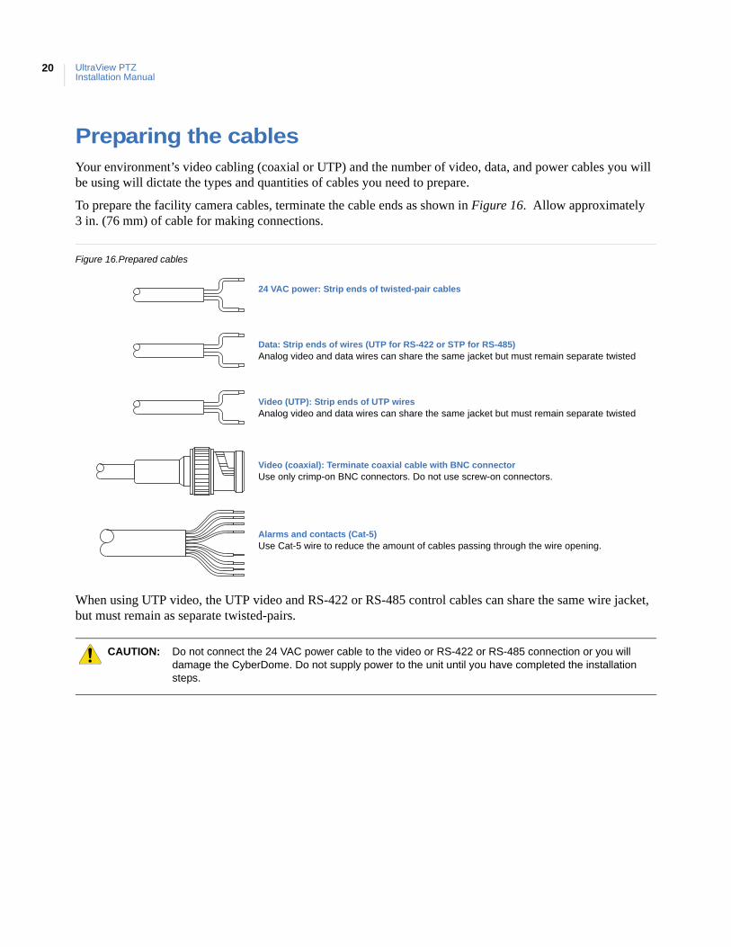
Preparing the cablesYour environment’s video cabling (coaxial or UTP) and the number of video, data, and power cables you will be using will dictate the types and quantities of cables you need to prepare.
To prepare the facility camera cables, terminate the cable ends as shown in Figure 16. Allow approximately 3 in. (76 mm) of cable for making connections.
Figure 16.Prepared cables
When using UTP video, the UTP video and RS-422 or RS-485 control cables can share the same wire jacket, but must remain as separate twisted-pairs.
CAUTION: Do not connect the 24 VAC power cable to the video or RS-422 or RS-485 connection or you will damage the CyberDome. Do not supply power to the unit until you have completed the installation steps.
24 VAC power: Strip ends of twisted-pair cables
Video (UTP): Strip ends of UTP wiresAnalog video and data wires can share the same jacket but must remain separate twisted
Video (coaxial): Terminate coaxial cable with BNC connectorUse only crimp-on BNC connectors. Do not use screw-on connectors.
Alarms and contacts (Cat-5)Use Cat-5 wire to reduce the amount of cables passing through the wire opening.
Data: Strip ends of wires (UTP for RS-422 or STP for RS-485)Analog video and data wires can share the same jacket but must remain separate twisted
This chapter explains how to wire the dome. One of the two boards that you will be handling while you wire the dome is inside of the housing.
In this chapter:
Components used for basic and advanced operation . . . . . . . . . . . . . . .22Wiring the housing board . . . . . . . . . . . . . . . . . . . . . . . . . . . . . . . . . . . .24Setting the termination . . . . . . . . . . . . . . . . . . . . . . . . . . . . . . . . . . . . . .26
Chapter 3 Wiring
UltraViews PTZInstallation Manual
22
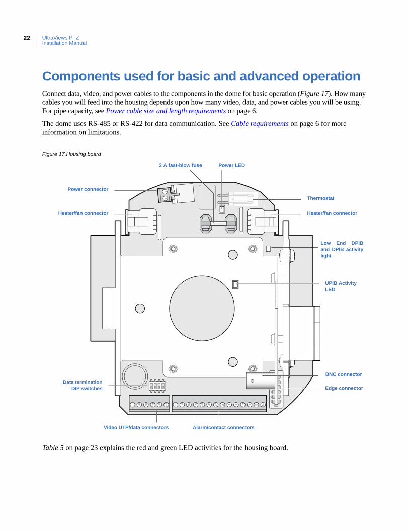
Components used for basic and advanced operationConnect data, video, and power cables to the components in the dome for basic operation (Figure 17). How many cables you will feed into the housing depends upon how many video, data, and power cables you will be using. For pipe capacity, see Power cable size and length requirements on page 6.
The dome uses RS-485 or RS-422 for data communication. See Cable requirements on page 6 for more information on limitations.
Figure 17.Housing board
Table 5 on page 23 explains the red and green LED activities for the housing board.
UPIB Activity LED
Edge connector
Alarm/contact connectorsVideo UTP/data connectors
Heater/fan connector Heater/fan connector
Power connector
Thermostat
Power LED2 A fast-blow fuse
Data terminationDIP switches
BNC connector
Low End DPIBand DPIB activitylight
Chapter 3Wiring
23
Alarm/contact connectors
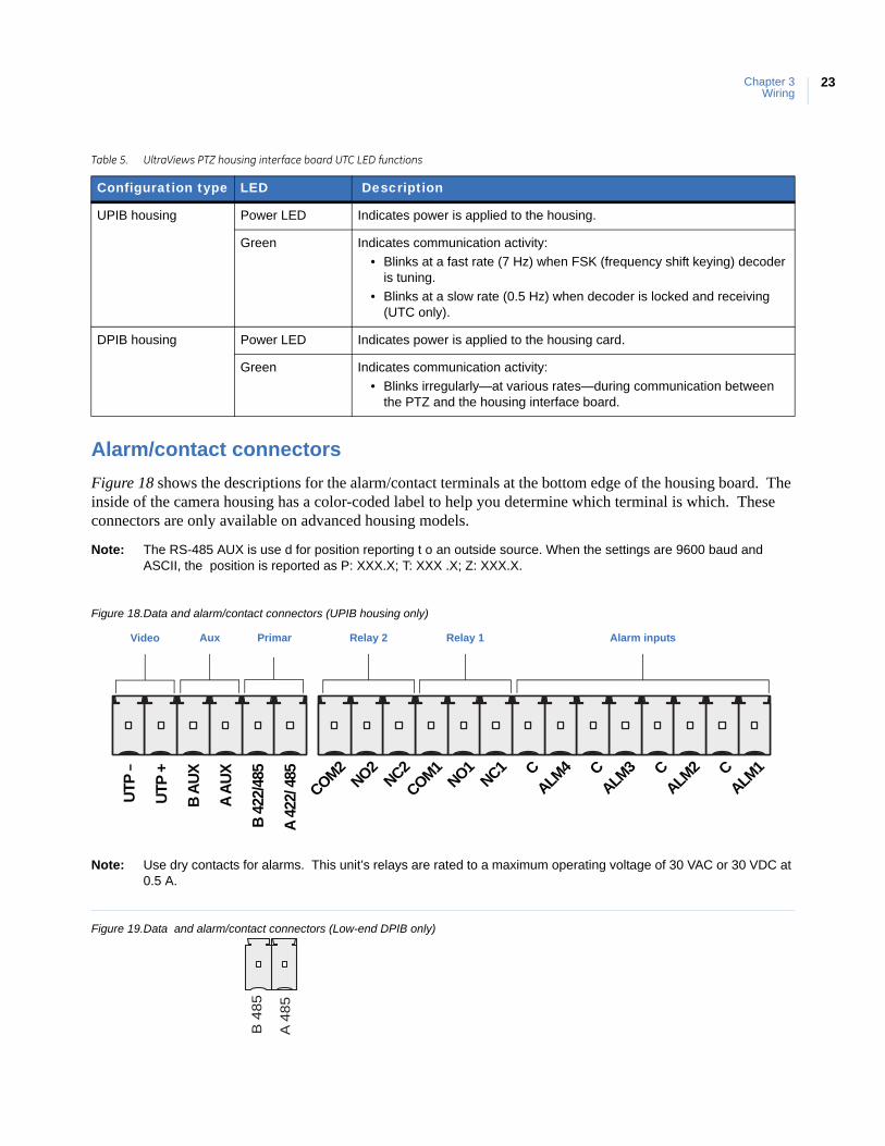
Figure 18 shows the descriptions for the alarm/contact terminals at the bottom edge of the housing board. The inside of the camera housing has a color-coded label to help you determine which terminal is which. These connectors are only available on advanced housing models.
Note: The RS-485 AUX is use d for position reporting t o an outside source. When the settings are 9600 baud and ASCII, the position is reported as P: XXX.X; T: XXX .X; Z: XXX.X.
Figure 18.Data and alarm/contact connectors (UPIB housing only)
Note: Use dry contacts for alarms. This unit’s relays are rated to a maximum operating voltage of 30 VAC or 30 VDC at 0.5 A.
Figure 19.Data and alarm/contact connectors (Low-end DPIB only)
Table 5. UltraViews PTZ housing interface board UTC LED functions
Configuration type LED Description
UPIB housing Power LED Indicates power is applied to the housing.
Green Indicates communication activity:
• Blinks at a fast rate (7 Hz) when FSK (frequency shift keying) decoder is tuning.
• Blinks at a slow rate (0.5 Hz) when decoder is locked and receiving (UTC only).
DPIB housing Power LED Indicates power is applied to the housing card.
Green Indicates communication activity:
• Blinks irregularly—at various rates—during communication between the PTZ and the housing interface board.
CALM
1ALM
3 CALM
2CALM
4 CCOM1
NO1NC1
COM2NO2
NC2
A AU
X
B 42
2/48
5
A 42
2/ 4
85
UTP ‒
UTP
+
B AU
X
Primar Alarm inputsRelay 1Relay 2AuxVideo
B 4
85
A 48
5
UltraViews PTZInstallation Manual
24
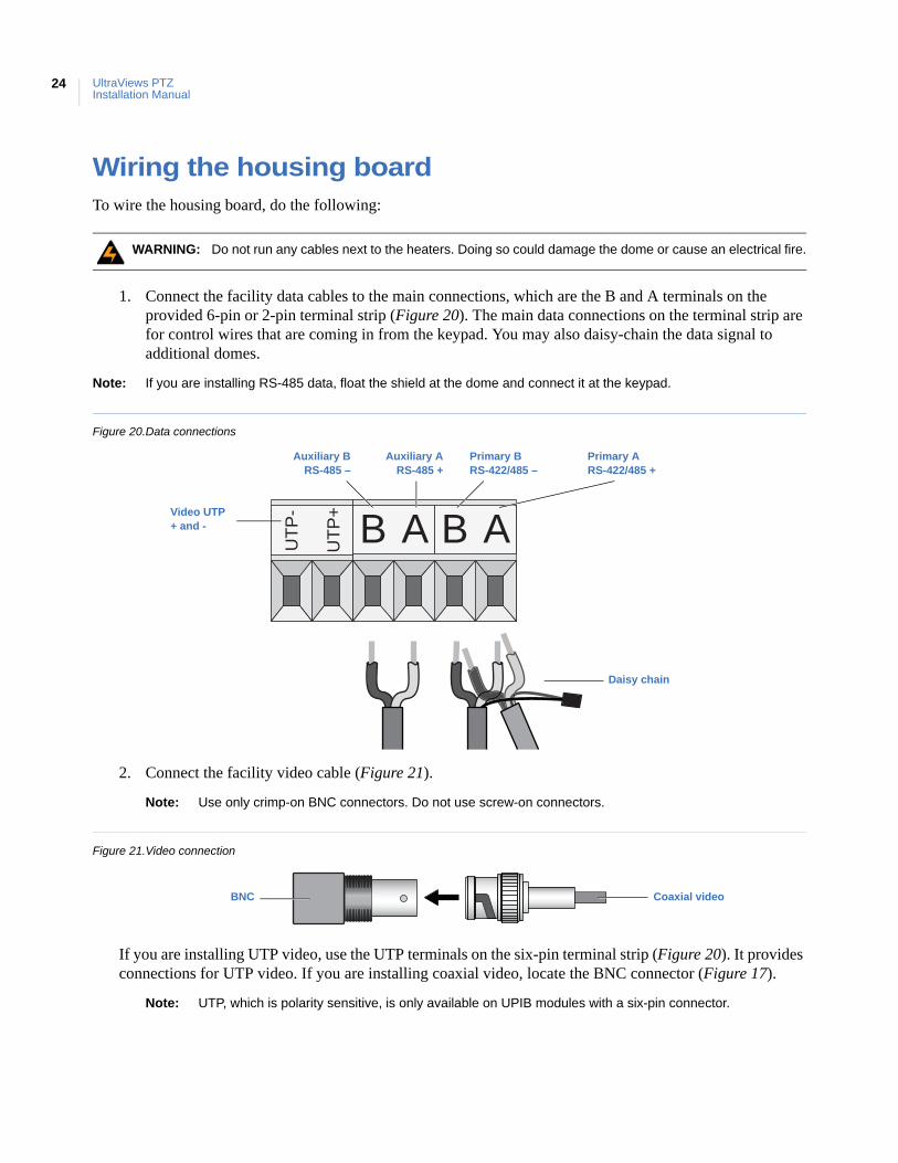
Wiring the housing boardTo wire the housing board, do the following:
1. Connect the facility data cables to the main connections, which are the B and A terminals on the provided 6-pin or 2-pin terminal strip (Figure 20). The main data connections on the terminal strip are for control wires that are coming in from the keypad. You may also daisy-chain the data signal to additional domes.
Note: If you are installing RS-485 data, float the shield at the dome and connect it at the keypad.
Figure 20.Data connections
2. Connect the facility video cable (Figure 21).
Note: Use only crimp-on BNC connectors. Do not use screw-on connectors.
Figure 21.Video connection
If you are installing UTP video, use the UTP terminals on the six-pin terminal strip (Figure 20). It provides connections for UTP video. If you are installing coaxial video, locate the BNC connector (Figure 17).
Note: UTP, which is polarity sensitive, is only available on UPIB modules with a six-pin connector.
WARNING: Do not run any cables next to the heaters. Doing so could damage the dome or cause an electrical fire.
B A B AUTP
-
UTP
+
Primary A RS-422/485 +
Auxiliary BRS-485 –
Primary B RS-422/485 –
Auxiliary ARS-485 +
Daisy chain
Video UTP + and -
Coaxial videoBNC
Chapter 3Wiring
25
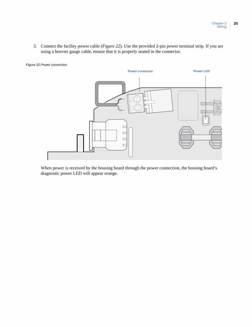
3. Connect the facility power cable (Figure 22). Use the provided 2-pin power terminal strip. If you are using a heavier gauge cable, ensure that it is properly seated in the connector.
Figure 22.Power connection
When power is received by the housing board through the power connection, the housing board’s diagnostic power LED will appear orange.
Power LEDPower connector
UltraViews PTZInstallation Manual
26
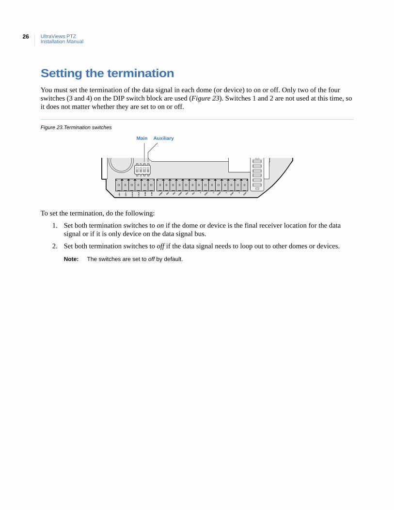
Setting the terminationYou must set the termination of the data signal in each dome (or device) to on or off. Only two of the four switches (3 and 4) on the DIP switch block are used (Figure 23). Switches 1 and 2 are not used at this time, so it does not matter whether they are set to on or off.
Figure 23.Termination switches
To set the termination, do the following:
1. Set both termination switches to on if the dome or device is the final receiver location for the data signal or if it is only device on the data signal bus.
2. Set both termination switches to off if the data signal needs to loop out to other domes or devices.
Note: The switches are set to off by default.
CALM
1ALM
3 CALM
2CALM
4 CCOM1
NO1NC1
COM2NO2
NC2
A AU
X
B 48
5
A 48
5
UTP ‒
UTP
+
B AU
X
Main Auxiliary
This chapter provides instructions for installing the camera assembly, a shroud, and a bubble dome.
In this chapter:
Camera assembly preparation and installation . . . . . . . . . . . . . . . . . . .28Setting the protocol . . . . . . . . . . . . . . . . . . . . . . . . . . . . . . . . . . . . . .29Setting the camera’s address . . . . . . . . . . . . . . . . . . . . . . . . . . . . . . .30Installing the camera assembly. . . . . . . . . . . . . . . . . . . . . . . . . . . . .32
Shroud and bubble dome installation . . . . . . . . . . . . . . . . . . . . . . . . . . .32Installing a camera shroud . . . . . . . . . . . . . . . . . . . . . . . . . . . . . . . .33Installing a bubble dome. . . . . . . . . . . . . . . . . . . . . . . . . . . . . . . . . .34
Chapter 4 Camera assembly, shroud, bubble dome
UltraView PTZInstallation Manual
28
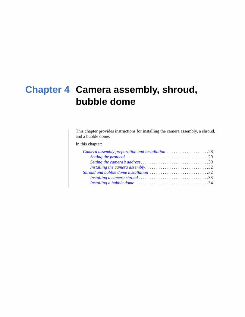
Camera assembly preparation and installationBefore you install the camera assembly in the housing, you should set the address and protocol DIP switches. UltraView PTZ has two multiposition DIP switch blocks: one on the upper board and one on the main board of the camera assembly (Figure 24). These DIP switches set the communication protocol and assign the camera a site address number respectively.
Figure 24.Protocol and site address DIP switch blocks
Protocol DIP switch block
Site address DIP switch block
Chapter 4Camera assembly, shroud, bubble dome
29
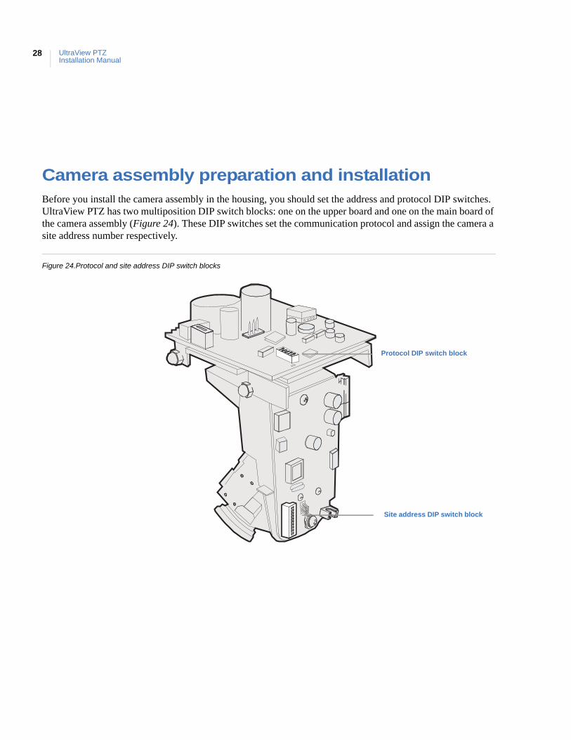
Setting the protocol
UltraView PTZ can use different protocols for communication. To select a protocol, you must set the protocol DIP switches to the correct sequence of 1s (on) and 0s (off).
To set the protocol DIP switches to select a protocol, do the following:
1. Locate the protocol DIP switch block (Figure 24 on page 28).
2. Using Table 6, find the DIP switch sequence for the desired protocol and set the switches accordingly.
UltraView PTZ stores programming settings in NVRAM in both the housing and the PTZ module. If the protocol switches are not set to one of the copy settings (01111 or 11111) and the two memories are different, Memory flashes onscreen. When you first log onto the menu system, you will be asked which settings you would like to use. For more information on protocol functionality with the UltraView PTZ camera, see Appendix B, Protocol functionality on page 49.
Table 6. Protocols
Protocol Switch position a
a. 1 = on, 0 = off.
Protocol Switch position a
Automatic selection b
b. The Automatic selection will automatically determine only the Interlogix protocols (Digiplex, Impac, and ASCII).
00000 AD RS-422 01010
Interlogix Digiplex RS-422 4800 10000 AD Manchester 10010
Interlogix Impac RS-485 9600 01000 Bosch RS-232 00110
Interlogix ASCII RS-422 9600 11000 Bosch biphase 10110
Pelco D autobaud 00100 Coaxitron 11110
Pelco P autobaud 10100 KD6 10001
Ultrak 9600 01100 Serial update 9600 11011
BBV 01110 Serial update 115200 00111
VCL 11100 Clear settings 10111
Panasonic 11010 Copy settings from PTZ to housing 01111
Vicon 00010 Copy settings from housing to PTZ 11111
UltraView PTZInstallation Manual
30
Setting the camera’s address
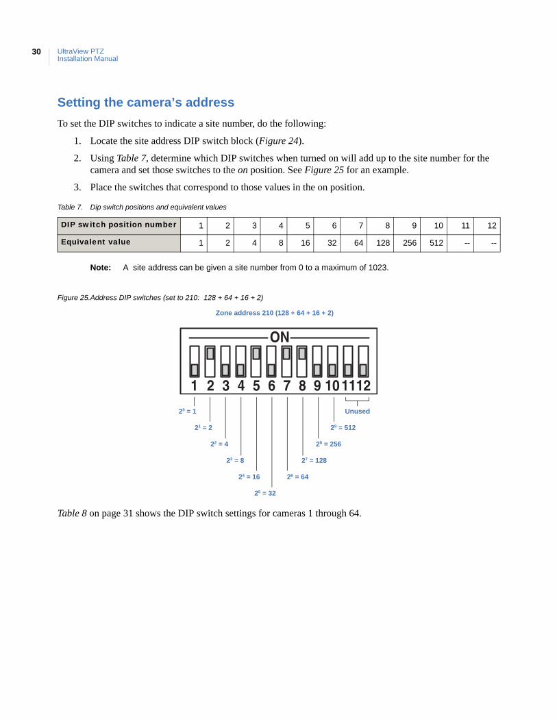
To set the DIP switches to indicate a site number, do the following:
1. Locate the site address DIP switch block (Figure 24).
2. Using Table 7, determine which DIP switches when turned on will add up to the site number for the camera and set those switches to the on position. See Figure 25 for an example.
3. Place the switches that correspond to those values in the on position.
Note: A site address can be given a site number from 0 to a maximum of 1023.
Figure 25.Address DIP switches (set to 210: 128 + 64 + 16 + 2)
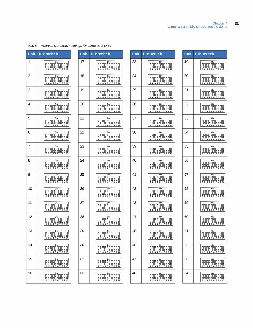
Table 8 on page 31 shows the DIP switch settings for cameras 1 through 64.
Table 7. Dip switch positions and equivalent values
DIP switch position number 1 2 3 4 5 6 7 8 9 10 11 12
Equivalent value 1 2 4 8 16 32 64 128 256 512 -- --
21 = 2
22 = 4
23 = 8
24 = 16
25 = 32
26 = 64
27 = 128
28 = 256
Unused20 = 1
29 = 512
Zone address 210 (128 + 64 + 16 + 2)
Chapter 4Camera assembly, shroud, bubble dome
31
Table 8. Address DIP switch settings for cameras 1 to 64
Unit DIP switch
1
2
3
4
5
6
7
8
9
10
11
12
13
14
15
16
17
18
19
20
21
22
23
24
25
26
27
28
29
30
31
32
Unit DIP switch
33
34
35
36
37
38
39
40
41
42
43
44
45
46
47
48
Unit DIP switch
49
50
51
52
53
54
55
56
57
58
59
60
61
62
63
64
Unit DIP switch
UltraView PTZInstallation Manual
32
Installing the camera assembly
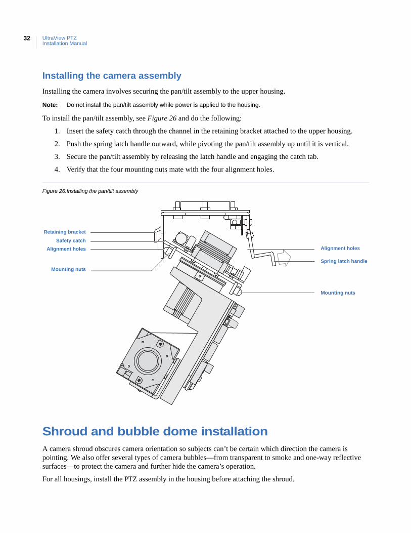
Installing the camera involves securing the pan/tilt assembly to the upper housing.
Note: Do not install the pan/tilt assembly while power is applied to the housing.
To install the pan/tilt assembly, see Figure 26 and do the following:
1. Insert the safety catch through the channel in the retaining bracket attached to the upper housing.
2. Push the spring latch handle outward, while pivoting the pan/tilt assembly up until it is vertical.
3. Secure the pan/tilt assembly by releasing the latch handle and engaging the catch tab.
4. Verify that the four mounting nuts mate with the four alignment holes.
Figure 26.Installing the pan/tilt assembly
Shroud and bubble dome installationA camera shroud obscures camera orientation so subjects can’t be certain which direction the camera is pointing. We also offer several types of camera bubbles—from transparent to smoke and one-way reflective surfaces—to protect the camera and further hide the camera’s operation.
For all housings, install the PTZ assembly in the housing before attaching the shroud.
Alignment holes
Spring latch handle
Retaining bracket
Mounting nuts
Safety catch
Alignment holes
Mounting nuts
Chapter 4Camera assembly, shroud, bubble dome
33
Installing a camera shroud
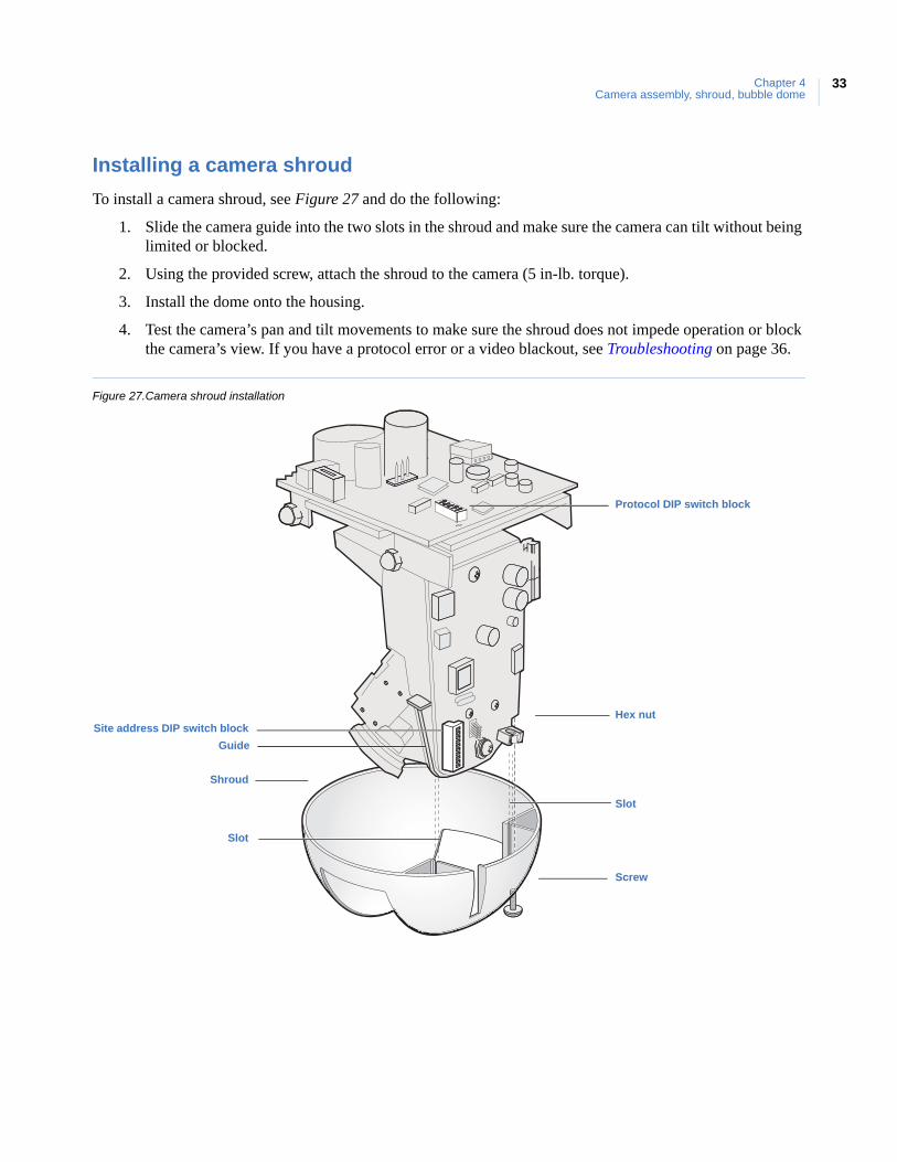
To install a camera shroud, see Figure 27 and do the following:
1. Slide the camera guide into the two slots in the shroud and make sure the camera can tilt without being limited or blocked.
2. Using the provided screw, attach the shroud to the camera (5 in-lb. torque).
3. Install the dome onto the housing.
4. Test the camera’s pan and tilt movements to make sure the shroud does not impede operation or block the camera’s view. If you have a protocol error or a video blackout, see Troubleshooting on page 36.
Figure 27.Camera shroud installation
Protocol DIP switch block
Site address DIP switch blockHex nut
Screw
Guide
Slot
Slot
Shroud
UltraView PTZInstallation Manual
34
Installing a bubble dome
There are a variety of bubble domes and housings. The interlocking clips and safety cables may vary, but all domes have them.
To attach a bubble dome to the housing, see Figure 28 on page 35 and do the following:
1. Fasten the dome safety cable to the housing’s safety clip.
2. Swing the dome up to the housing and align the dome’s screws with the housing’s dome screw holes.
If you are installing a plastic pendant-mount housing, there are alignment guides on the housing ring that straddle the rear-facing screw hole of the dome ring.
3. Use the following guidelines for tightening the dome screws.
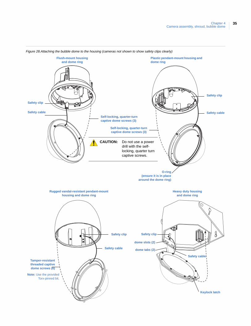
• If you are installing a plastic pendant-mount or flush-mount housing, the dome screws are self-locking, quarter-turn captive screws and require only a quarter turn to tighten.
• If you are installing a flush-mount housing, the dome ring contains a foam pad that requires you to push up while turning the screws.
• If you are installing the dome on a rugged vandal-resistant housing, the screws are tamper-resistant and require the provided security torx-pinned bit for tightening. Do not tighten these screws to more than 17 lb. inches (192 cNm) in torque.
• If you are installing the dome on a heavy-duty housing, attach the keylock latch before tightening the screws.
4. Clean any fingerprints off of the dome. See Cleaning the bubble dome on page 37.
CAUTION: To prevent damage, do not touch the dome with your bare hands, do not place the dome face down on any surface, and protect the dome from dust. Oil and acid residue from your hands can etch some dome surfaces and is difficult to remove. Use a scratch-resistant cloth or gloves when handling the dome.
CAUTION: Do not use a power drill with the self-locking, quarter-turn captive screws. A power drill can strip the heads of the screws or the inside of the screw inserts (in the housing) enough to necessitate replacing the housing.
Chapter 4Camera assembly, shroud, bubble dome
35
Figure 28.Attaching the bubble dome to the housing (cameras not shown to show safety clips clearly)
Cameras not shownin diagrams
so that safety clipsare clearly visible.
Flush-mount housing and bubble ring
Safety cableSelf-locking, quarter-turn captive bubble screws (3)
Safety clip
Self-locking, quarter-turncaptive bubble screws (3)
Safety cable
Safety clip
Plastic pendant-mount housing and bubble ring
O-ring(ensure it is in place
around the bubble ring)
Tamper-resistantthreaded captivebubble screws (6)
Safety cable
Cast aluminum (rugged) pendant-mount housingand bubble ring
Safety clip
Safety sable
Keylock latch
Bubble slots (2)
Bubble tabs (2)
Safety clip
Heavy duty housing and bubble ring
Flush-mount housing and dome ring
Plastic pendant-mount housing and dome ring
Rugged vandal-resistant pendant-mount housing and dome ring
Heavy duty housing and dome ring
Self-locking, quarter-turn captive dome screws (3)
Self-locking, quarter-turn captive dome screws (3)
Safety clip
Safety cable
Safety clip
Safety cable
O-ring(ensure it is in place
around the dome ring)
Tamper-resistantthreaded captivedome screws (6)
Safety clip Safety clip
Safety cable
dome slots (2)
dome tabs (2)
Safety cable
Keylock latch
Note: Use the providedTorx-pinned bit.
CAUTION: Do not use a power drill with the self-locking, quarter turn captive screws.

UltraView PTZInstallation Manual
36
This chapter provides information to help you troubleshoot problems, perform simple preventive maintenance procedures, and contact technical support in case you need assistance with your Interlogix equipment.
In this chapter:
Troubleshooting . . . . . . . . . . . . . . . . . . . . . . . . . . . . . . . . . . . . . . . . . . . .38Maintenance . . . . . . . . . . . . . . . . . . . . . . . . . . . . . . . . . . . . . . . . . . . . . .39
Cleaning the bubble dome . . . . . . . . . . . . . . . . . . . . . . . . . . . . . . . .39Contacting us. . . . . . . . . . . . . . . . . . . . . . . . . . . . . . . . . . . . . . . . . . . . . .40
Online . . . . . . . . . . . . . . . . . . . . . . . . . . . . . . . . . . . . . . . . . . . . . . . .40
Chapter 5 Troubleshooting, maintenance, support
UltraView PTZInstallation Manual
38
TroubleshootingThis section provides information to help you diagnose and solve various problems that may arise while configuring or using your Interloix product.
Housing board power indication
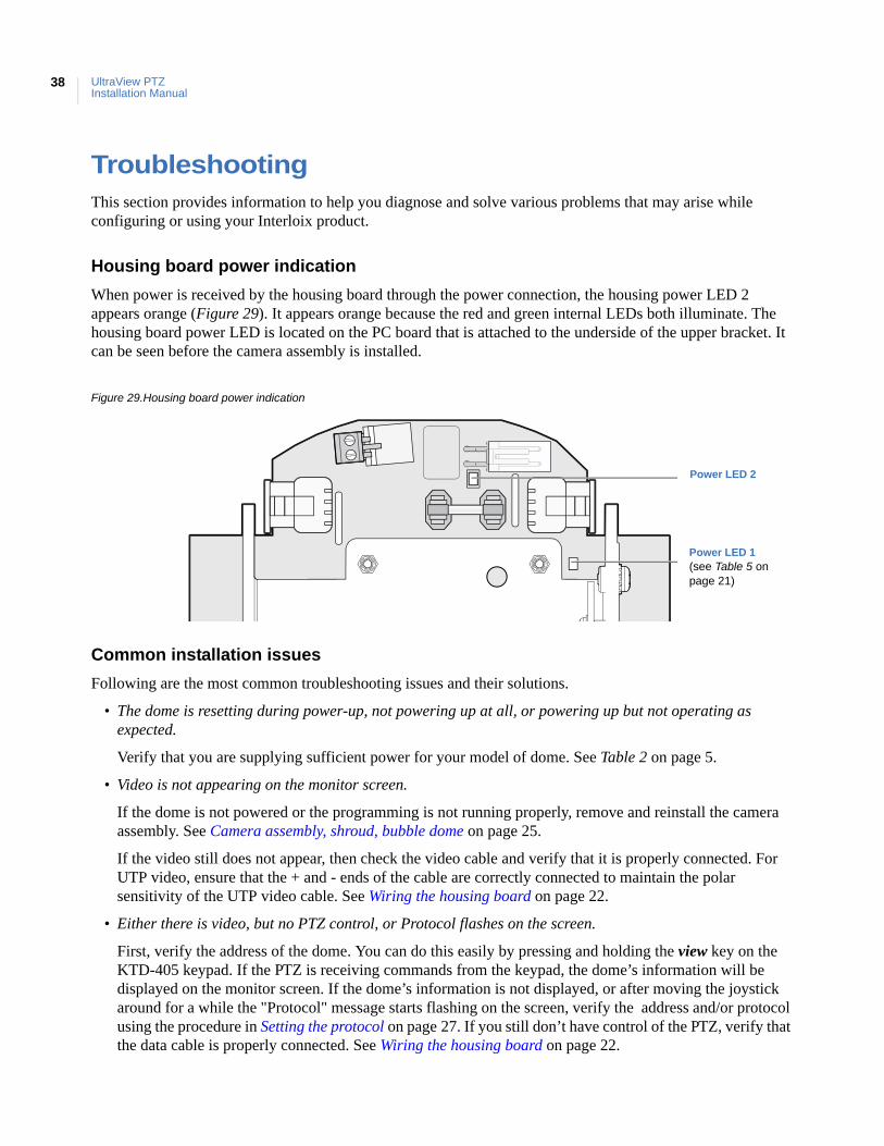
When power is received by the housing board through the power connection, the housing power LED 2 appears orange (Figure 29). It appears orange because the red and green internal LEDs both illuminate. The housing board power LED is located on the PC board that is attached to the underside of the upper bracket. It can be seen before the camera assembly is installed.
Figure 29.Housing board power indication
Common installation issues
Following are the most common troubleshooting issues and their solutions.
• The dome is resetting during power-up, not powering up at all, or powering up but not operating as expected.
Verify that you are supplying sufficient power for your model of dome. See Table 2 on page 5.
• Video is not appearing on the monitor screen.
If the dome is not powered or the programming is not running properly, remove and reinstall the camera assembly. See Camera assembly, shroud, bubble dome on page 25.
If the video still does not appear, then check the video cable and verify that it is properly connected. For UTP video, ensure that the + and - ends of the cable are correctly connected to maintain the polar sensitivity of the UTP video cable. See Wiring the housing board on page 22.
• Either there is video, but no PTZ control, or Protocol flashes on the screen.
First, verify the address of the dome. You can do this easily by pressing and holding the view key on the KTD-405 keypad. If the PTZ is receiving commands from the keypad, the dome’s information will be displayed on the monitor screen. If the dome’s information is not displayed, or after moving the joystick around for a while the "Protocol" message starts flashing on the screen, verify the address and/or protocol using the procedure in Setting the protocol on page 27. If you still don’t have control of the PTZ, verify that the data cable is properly connected. See Wiring the housing board on page 22.
Power LED 2
Power LED 1(see Table 5 on page 21)
Chapter 5Troubleshooting, maintenance, support
39
Finally, try resetting (cycling) the power to the dome by turning the power off then on.
MaintenancePerform the following maintenance, when necessary or directed to.
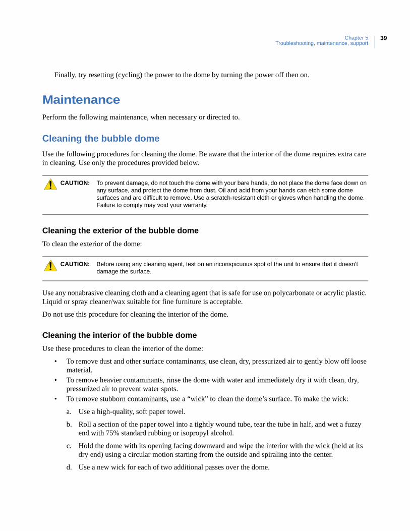
Cleaning the bubble dome
Use the following procedures for cleaning the dome. Be aware that the interior of the dome requires extra care in cleaning. Use only the procedures provided below.
Cleaning the exterior of the bubble dome
To clean the exterior of the dome:
Use any nonabrasive cleaning cloth and a cleaning agent that is safe for use on polycarbonate or acrylic plastic. Liquid or spray cleaner/wax suitable for fine furniture is acceptable.
Do not use this procedure for cleaning the interior of the dome.
Cleaning the interior of the bubble dome
Use these procedures to clean the interior of the dome:
• To remove dust and other surface contaminants, use clean, dry, pressurized air to gently blow off loose material.
• To remove heavier contaminants, rinse the dome with water and immediately dry it with clean, dry, pressurized air to prevent water spots.
• To remove stubborn contaminants, use a “wick” to clean the dome’s surface. To make the wick:
a. Use a high-quality, soft paper towel.
b. Roll a section of the paper towel into a tightly wound tube, tear the tube in half, and wet a fuzzy end with 75% standard rubbing or isopropyl alcohol.
c. Hold the dome with its opening facing downward and wipe the interior with the wick (held at its dry end) using a circular motion starting from the outside and spiraling into the center.
d. Use a new wick for each of two additional passes over the dome.
CAUTION: To prevent damage, do not touch the dome with your bare hands, do not place the dome face down on any surface, and protect the dome from dust. Oil and acid from your hands can etch some dome surfaces and are difficult to remove. Use a scratch-resistant cloth or gloves when handling the dome. Failure to comply may void your warranty.
CAUTION: Before using any cleaning agent, test on an inconspicuous spot of the unit to ensure that it doesn’t damage the surface.
UltraView PTZInstallation Manual
40
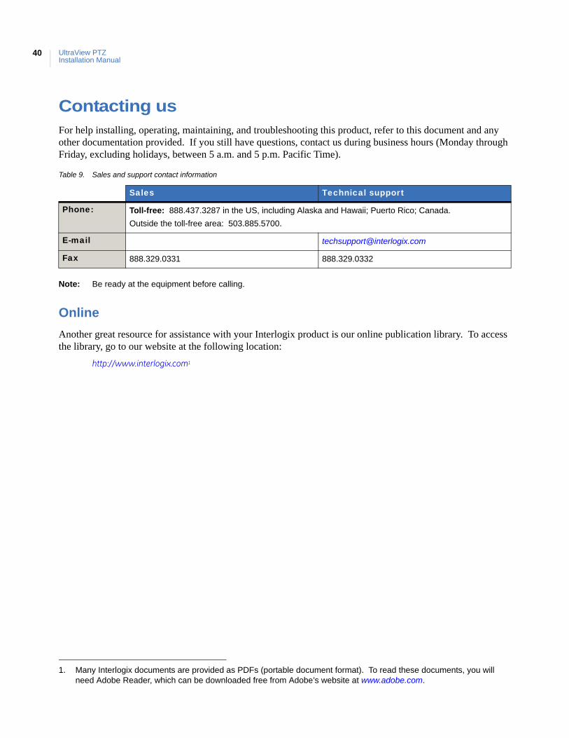
Contacting usFor help installing, operating, maintaining, and troubleshooting this product, refer to this document and any other documentation provided. If you still have questions, contact us during business hours (Monday through Friday, excluding holidays, between 5 a.m. and 5 p.m. Pacific Time).
Note: Be ready at the equipment before calling.
Online
Another great resource for assistance with your Interlogix product is our online publication library. To access the library, go to our website at the following location:
http://www.interlogix.com1
Table 9. Sales and support contact information
Sales Technical support
Phone: Toll-free: 888.437.3287 in the US, including Alaska and Hawaii; Puerto Rico; Canada.
Outside the toll-free area: 503.885.5700.
E-mail [email protected]
Fax 888.329.0331 888.329.0332
1. Many Interlogix documents are provided as PDFs (portable document format). To read these documents, you will need Adobe Reader, which can be downloaded free from Adobe’s website at www.adobe.com.
This appendix provides the installation instructions for the mounts that are shipped with the dome kits. Dome kits include a wall-mount arm and a T-bar support kit. Instructions for all other mounts (arms, adapters, and brackets) are shipped with those mounts.
In this appendix:
GEA-102 wall-mount arm . . . . . . . . . . . . . . . . . . . . . . . . . . . . . . . . . . . .42Installing the wall-mount arm. . . . . . . . . . . . . . . . . . . . . . . . . . . . . .42Opening a conduit hole . . . . . . . . . . . . . . . . . . . . . . . . . . . . . . . . . . .45
GEA-114 T-bar ceiling support kit . . . . . . . . . . . . . . . . . . . . . . . . . . . . .47Installing the T-bar ceiling support kit . . . . . . . . . . . . . . . . . . . . . . .47
Appendix A Mount kits
UltraView PTZInstallation Manual
42
GEA-102 wall-mount armThis cast aluminum wall-mount arm is used to mount a dome to a vertical surface. It is for indoor or outdoor use and mates with both the plastic indoor and cast aluminum outdoor pendant housings. It can be attached directly to a vertical surface or mated with a bracket (corner-mount, pole-mount, or roof-mount). Instructions for mating this mount to the various brackets are provided in the instructions for those brackets. The following instructions explain how to install the wall-mount arm directly to a vertical surface.
Installing the wall-mount arm
To install the wall-mount arm, see the corresponding figures and do the following:
1. The facility cables usually come out of the mounting surface and enter the arm through the rear opening in the base. If the cables are attached externally to the mounting surface and need to enter the arm through the side, open a conduit hole in the side of the arm with the instructions given in Opening a conduit hole on page 45.
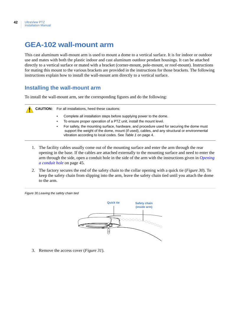
2. The factory secures the end of the safety chain to the collar opening with a quick tie (Figure 30). To keep the safety chain from slipping into the arm, leave the safety chain tied until you attach the dome to the arm.
Figure 30.Leaving the safety chain tied
3. Remove the access cover (Figure 31).
CAUTION: For all installations, heed these cautions:
• Complete all installation steps before supplying power to the dome.
• To ensure proper operation of a PTZ unit, install the mount level.
• For safety, the mounting surface, hardware, and procedure used for securing the dome must support the weight of the dome, mount (if used), cables, and any structural or environmentalvibration according to local codes. See Table 1 on page 4.
Quick tie Safety chain(inside arm)
43
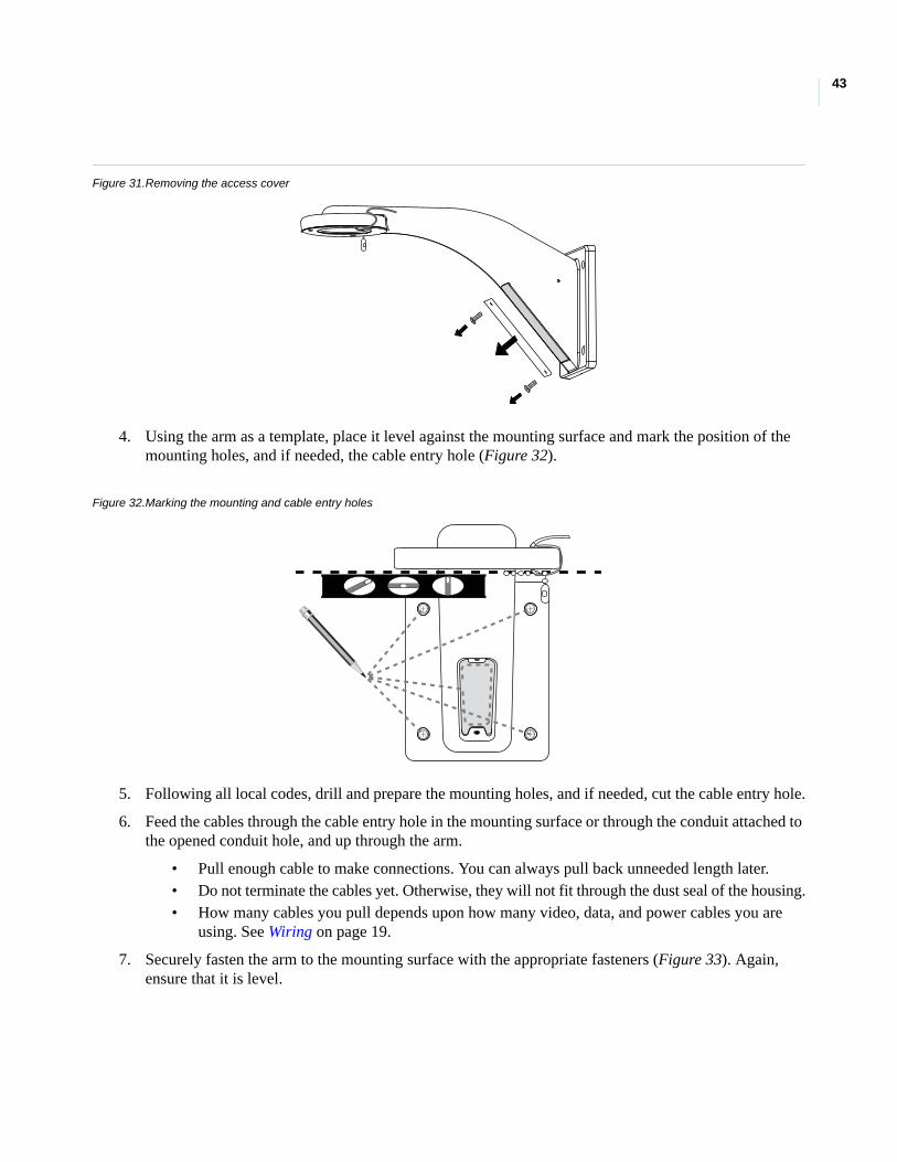
Figure 31.Removing the access cover
4. Using the arm as a template, place it level against the mounting surface and mark the position of the mounting holes, and if needed, the cable entry hole (Figure 32).
Figure 32.Marking the mounting and cable entry holes
5. Following all local codes, drill and prepare the mounting holes, and if needed, cut the cable entry hole.
6. Feed the cables through the cable entry hole in the mounting surface or through the conduit attached to the opened conduit hole, and up through the arm.
• Pull enough cable to make connections. You can always pull back unneeded length later.• Do not terminate the cables yet. Otherwise, they will not fit through the dust seal of the housing.• How many cables you pull depends upon how many video, data, and power cables you are
using. See Wiring on page 19.
7. Securely fasten the arm to the mounting surface with the appropriate fasteners (Figure 33). Again, ensure that it is level.
UltraView PTZInstallation Manual
44
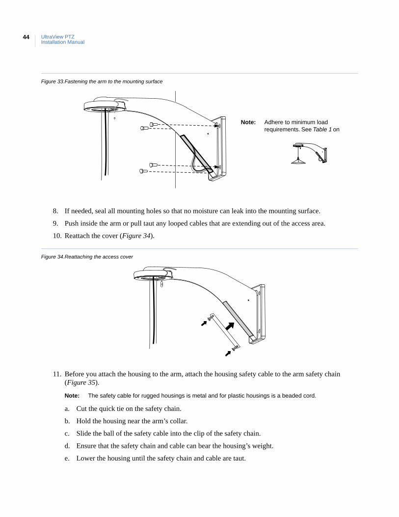
Figure 33.Fastening the arm to the mounting surface
8. If needed, seal all mounting holes so that no moisture can leak into the mounting surface.
9. Push inside the arm or pull taut any looped cables that are extending out of the access area.
10. Reattach the cover (Figure 34).
Figure 34.Reattaching the access cover
11. Before you attach the housing to the arm, attach the housing safety cable to the arm safety chain (Figure 35).
Note: The safety cable for rugged housings is metal and for plastic housings is a beaded cord.
a. Cut the quick tie on the safety chain.
b. Hold the housing near the arm’s collar.
c. Slide the ball of the safety cable into the clip of the safety chain.
d. Ensure that the safety chain and cable can bear the housing’s weight.
e. Lower the housing until the safety chain and cable are taut.
Note: Adhere to minimum load requirements. See Table 1 on
45
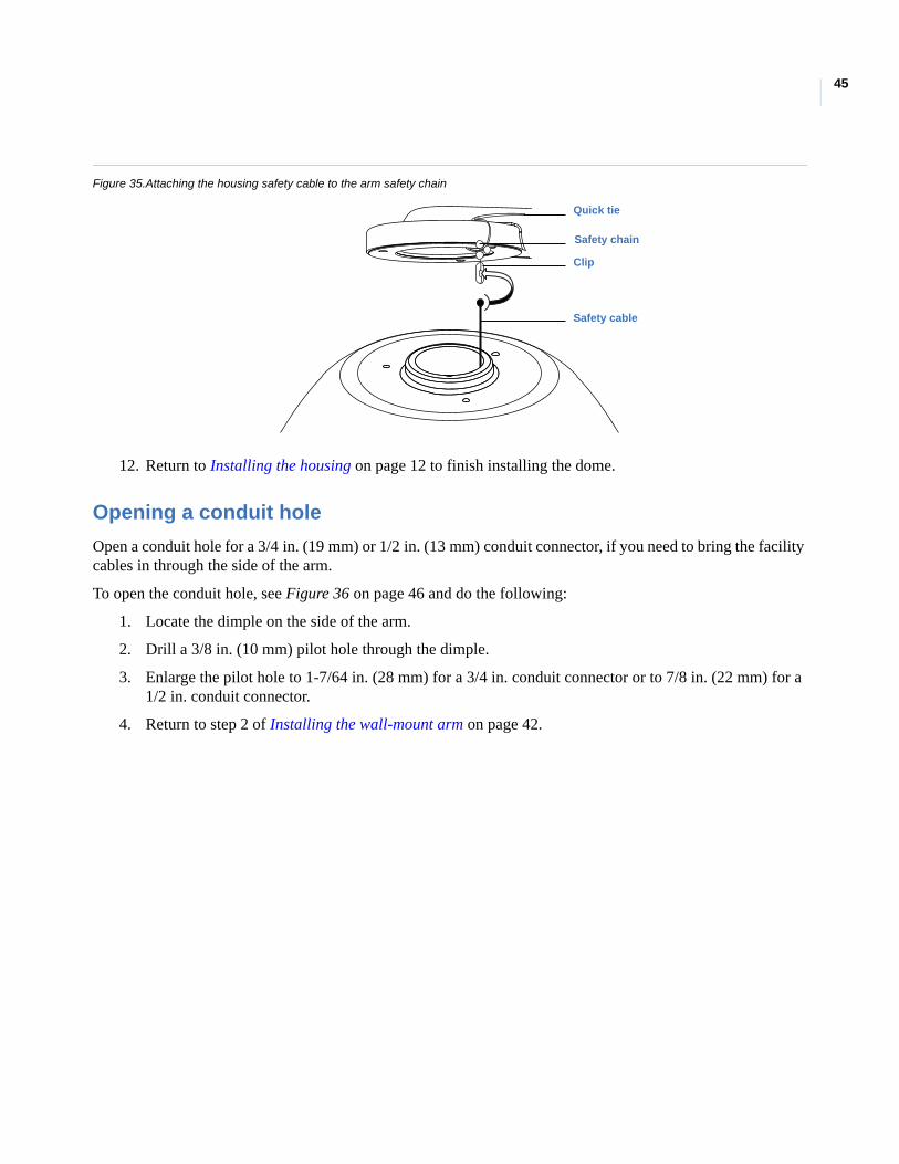
Figure 35.Attaching the housing safety cable to the arm safety chain
12. Return to Installing the housing on page 12 to finish installing the dome.
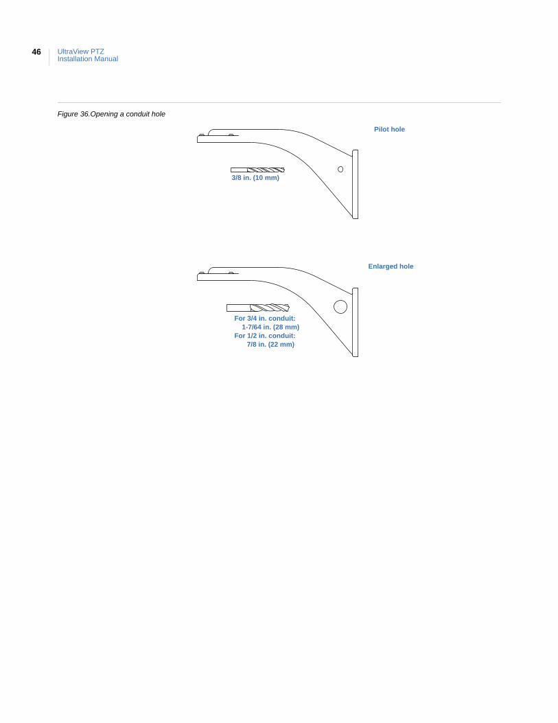
Opening a conduit hole
Open a conduit hole for a 3/4 in. (19 mm) or 1/2 in. (13 mm) conduit connector, if you need to bring the facility cables in through the side of the arm.
To open the conduit hole, see Figure 36 on page 46 and do the following:
1. Locate the dimple on the side of the arm.
2. Drill a 3/8 in. (10 mm) pilot hole through the dimple.
3. Enlarge the pilot hole to 1-7/64 in. (28 mm) for a 3/4 in. conduit connector or to 7/8 in. (22 mm) for a 1/2 in. conduit connector.
4. Return to step 2 of Installing the wall-mount arm on page 42.
Quick tie
Safety chain
Clip
Safety cable
UltraView PTZInstallation Manual
46
Figure 36.Opening a conduit hole
Pilot hole
Enlarged hole
3/8 in. (10 mm)
For 3/4 in. conduit: 1-7/64 in. (28 mm)
For 1/2 in. conduit: 7/8 in. (22 mm)
47
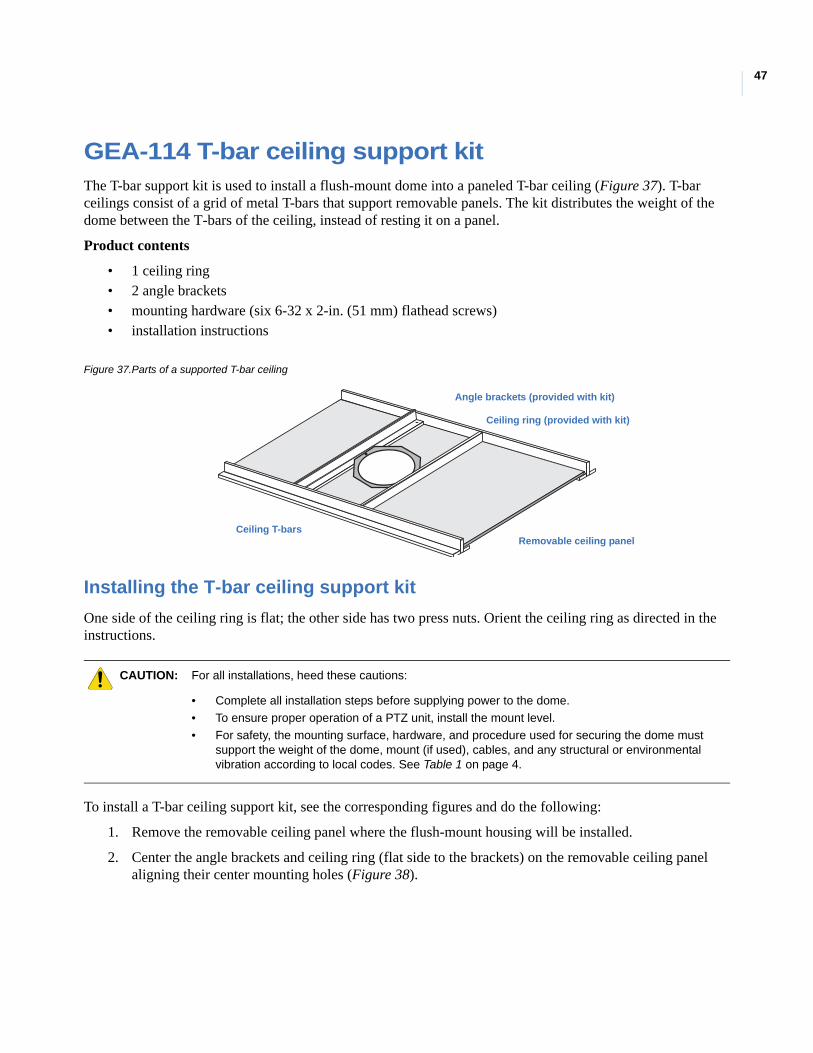
GEA-114 T-bar ceiling support kitThe T-bar support kit is used to install a flush-mount dome into a paneled T-bar ceiling (Figure 37). T-bar ceilings consist of a grid of metal T-bars that support removable panels. The kit distributes the weight of the dome between the T-bars of the ceiling, instead of resting it on a panel.
Product contents
• 1 ceiling ring• 2 angle brackets• mounting hardware (six 6-32 x 2-in. (51 mm) flathead screws)• installation instructions
Figure 37.Parts of a supported T-bar ceiling
Installing the T-bar ceiling support kit
One side of the ceiling ring is flat; the other side has two press nuts. Orient the ceiling ring as directed in the instructions.
To install a T-bar ceiling support kit, see the corresponding figures and do the following:
1. Remove the removable ceiling panel where the flush-mount housing will be installed.
2. Center the angle brackets and ceiling ring (flat side to the brackets) on the removable ceiling panel aligning their center mounting holes (Figure 38).
CAUTION: For all installations, heed these cautions:
• Complete all installation steps before supplying power to the dome.
• To ensure proper operation of a PTZ unit, install the mount level.
• For safety, the mounting surface, hardware, and procedure used for securing the dome mustsupport the weight of the dome, mount (if used), cables, and any structural or environmentalvibration according to local codes. See Table 1 on page 4.
Angle brackets (provided with kit)
Removable ceiling panelCeiling T-bars
Ceiling ring (provided with kit)
UltraView PTZInstallation Manual
48
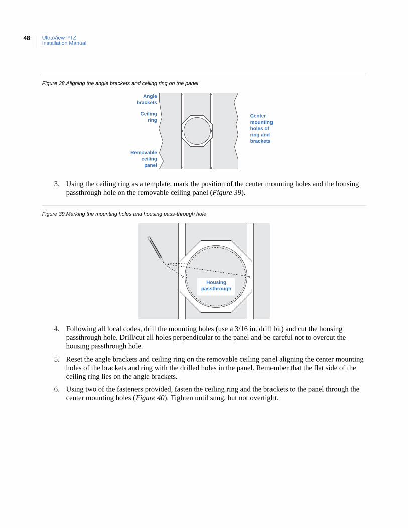
Figure 38.Aligning the angle brackets and ceiling ring on the panel
3. Using the ceiling ring as a template, mark the position of the center mounting holes and the housing passthrough hole on the removable ceiling panel (Figure 39).
Figure 39.Marking the mounting holes and housing pass-through hole
4. Following all local codes, drill the mounting holes (use a 3/16 in. drill bit) and cut the housing passthrough hole. Drill/cut all holes perpendicular to the panel and be careful not to overcut the housing passthrough hole.
5. Reset the angle brackets and ceiling ring on the removable ceiling panel aligning the center mounting holes of the brackets and ring with the drilled holes in the panel. Remember that the flat side of the ceiling ring lies on the angle brackets.
6. Using two of the fasteners provided, fasten the ceiling ring and the brackets to the panel through the center mounting holes (Figure 40). Tighten until snug, but not overtight.
Center mounting holes of ring and brackets
Anglebrackets
Ceilingring
Removableceiling
panel
Housingpassthrough
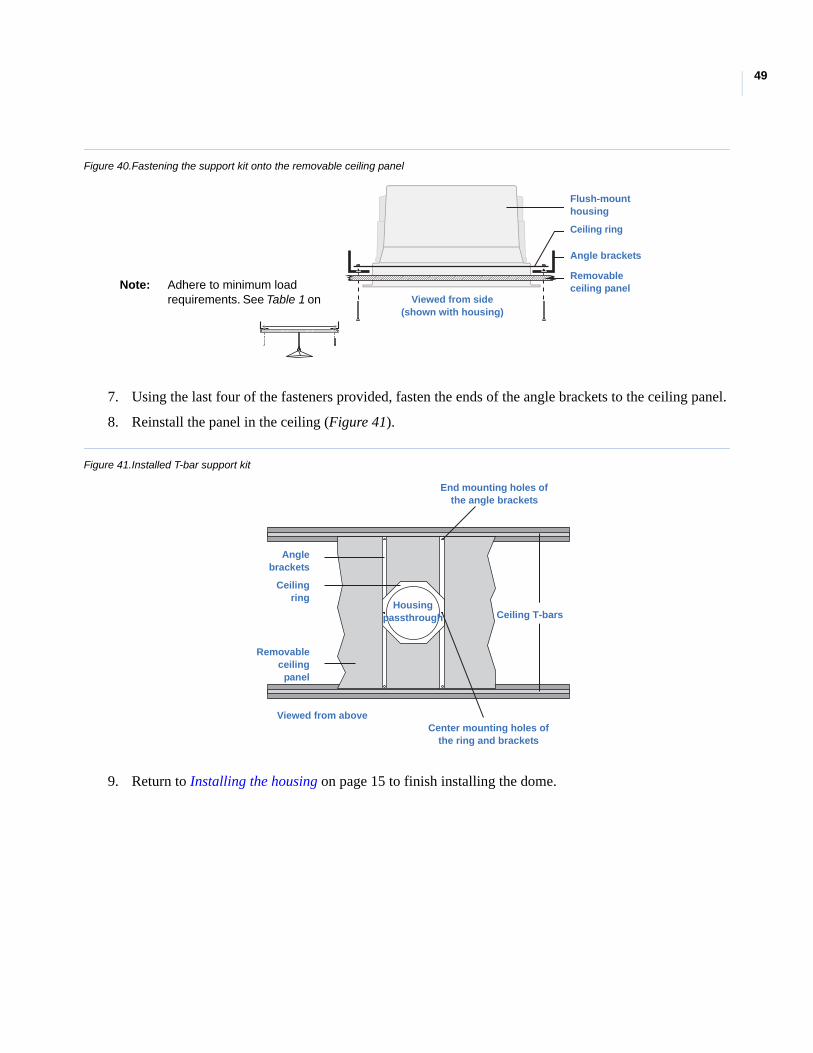
49
Figure 40.Fastening the support kit onto the removable ceiling panel
7. Using the last four of the fasteners provided, fasten the ends of the angle brackets to the ceiling panel.
8. Reinstall the panel in the ceiling (Figure 41).
Figure 41.Installed T-bar support kit
9. Return to Installing the housing on page 15 to finish installing the dome.
Flush-mount housing
Ceiling ring
Angle brackets
Removableceiling panel
Viewed from side(shown with housing)
Note: Adhere to minimum load requirements. See Table 1 on
End mounting holes of the angle brackets
Ceiling T-bars
Center mounting holes of the ring and brackets
Housingpassthrough
Viewed from above
Anglebrackets
Ceilingring
Removable ceiling
panel

UltraView PTZInstallation Manual
50
Appendix B Protocol functionality
This appendix provides information on protocol functionality.
In this appendix:
UltraView PTZ protocol functionality . . . . . . . . . . . . . . . . . . . . . . . . . . .52Equipment protocol testing list . . . . . . . . . . . . . . . . . . . . . . . . . . . . . . . .56
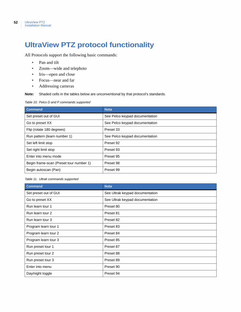
UltraView PTZInstallation Manual
52
UltraView PTZ protocol functionalityAll Protocols support the following basic commands:
• Pan and tilt• Zoom—wide and telephoto• Iris—open and close• Focus—near and far• Addressing cameras
Note: Shaded cells in the tables below are unconventional by that protocol’s standards.
Table 10. Pelco D and P commands supported
Command Note
Set preset out of GUI See Pelco keypad documentation
Go to preset XX See Pelco keypad documentation
Flip (rotate 180 degrees) Preset 33
Run pattern (learn number 1) See Pelco keypad documentation
Set left limit stop Preset 92
Set right limit stop Preset 93
Enter into menu mode Preset 95
Begin frame-scan (Preset tour number 1) Preset 98
Begin autoscan (Pan) Preset 99
Table 11. Ultrak commands supported
Command Note
Set preset out of GUI See Ultrak keypad documentation
Go to preset XX See Ultrak keypad documentation
Run learn tour 1 Preset 80
Run learn tour 2 Preset 81
Run learn tour 3 Preset 82
Program learn tour 1 Preset 83
Program learn tour 2 Preset 84
Program learn tour 3 Preset 85
Run preset tour 1 Preset 87
Run preset tour 2 Preset 88
Run preset tour 3 Preset 89
Enter into menu Preset 90
Day/night toggle Preset 94
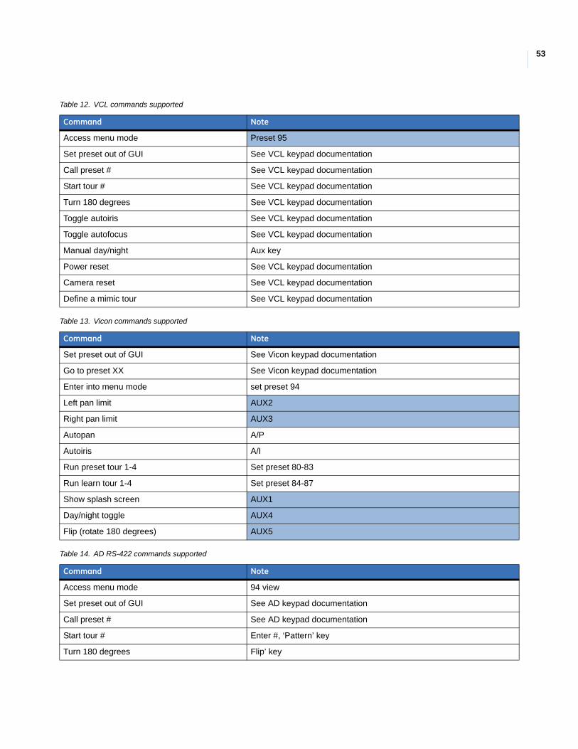
53
Table 12. VCL commands supported
Command Note
Access menu mode Preset 95
Set preset out of GUI See VCL keypad documentation
Call preset # See VCL keypad documentation
Start tour # See VCL keypad documentation
Turn 180 degrees See VCL keypad documentation
Toggle autoiris See VCL keypad documentation
Toggle autofocus See VCL keypad documentation
Manual day/night Aux key
Power reset See VCL keypad documentation
Camera reset See VCL keypad documentation
Define a mimic tour See VCL keypad documentation
Table 13. Vicon commands supported
Command Note
Set preset out of GUI See Vicon keypad documentation
Go to preset XX See Vicon keypad documentation
Enter into menu mode set preset 94
Left pan limit AUX2
Right pan limit AUX3
Autopan A/P
Autoiris A/I
Run preset tour 1-4 Set preset 80-83
Run learn tour 1-4 Set preset 84-87
Show splash screen AUX1
Day/night toggle AUX4
Flip (rotate 180 degrees) AUX5
Table 14. AD RS-422 commands supported
Command Note
Access menu mode 94 view
Set preset out of GUI See AD keypad documentation
Call preset # See AD keypad documentation
Start tour # Enter #, ‘Pattern’ key
Turn 180 degrees Flip’ key
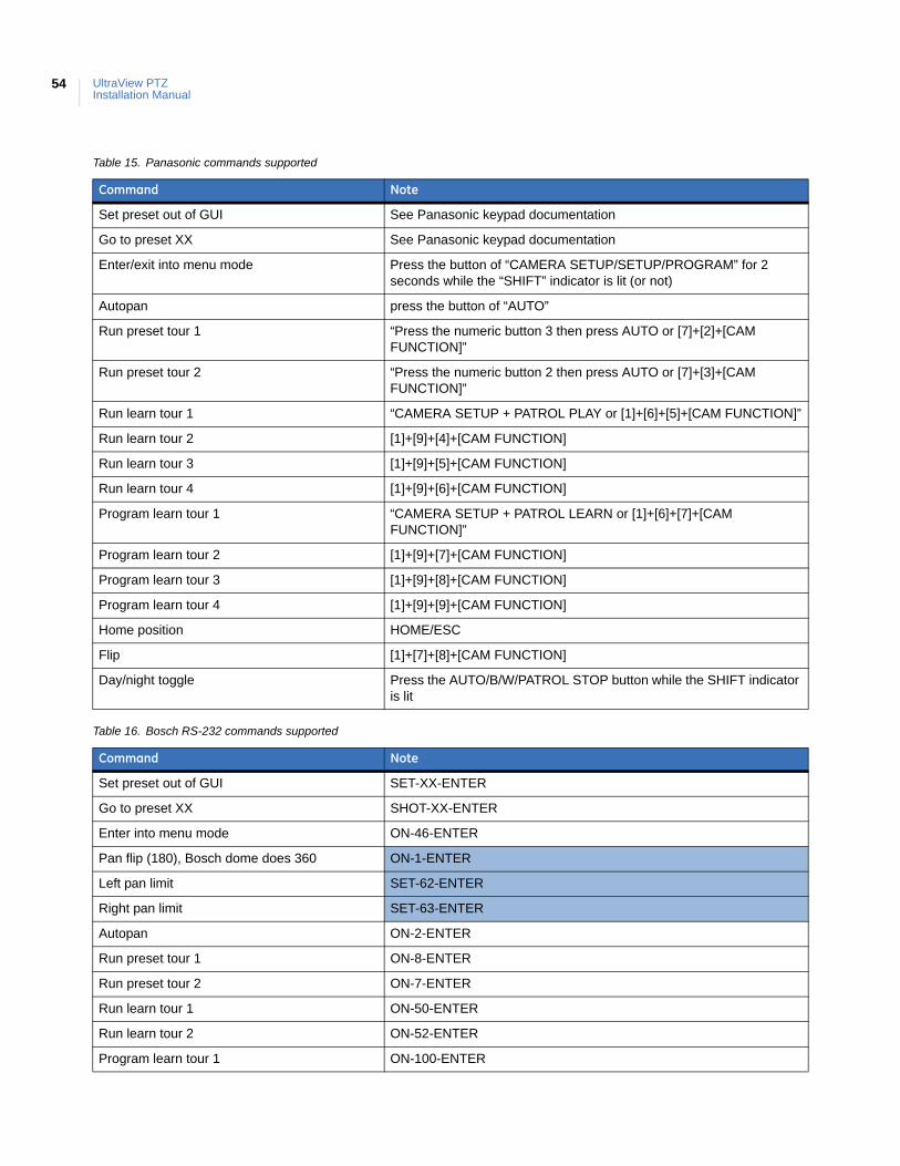
UltraView PTZInstallation Manual
54
Table 15. Panasonic commands supported
Command Note
Set preset out of GUI See Panasonic keypad documentation
Go to preset XX See Panasonic keypad documentation
Enter/exit into menu mode Press the button of “CAMERA SETUP/SETUP/PROGRAM” for 2 seconds while the “SHIFT” indicator is lit (or not)
Autopan press the button of “AUTO”
Run preset tour 1 “Press the numeric button 3 then press AUTO or [7]+[2]+[CAM FUNCTION]”
Run preset tour 2 “Press the numeric button 2 then press AUTO or [7]+[3]+[CAM FUNCTION]”
Run learn tour 1 “CAMERA SETUP + PATROL PLAY or [1]+[6]+[5]+[CAM FUNCTION]”
Run learn tour 2 [1]+[9]+[4]+[CAM FUNCTION]
Run learn tour 3 [1]+[9]+[5]+[CAM FUNCTION]
Run learn tour 4 [1]+[9]+[6]+[CAM FUNCTION]
Program learn tour 1 “CAMERA SETUP + PATROL LEARN or [1]+[6]+[7]+[CAM FUNCTION]”
Program learn tour 2 [1]+[9]+[7]+[CAM FUNCTION]
Program learn tour 3 [1]+[9]+[8]+[CAM FUNCTION]
Program learn tour 4 [1]+[9]+[9]+[CAM FUNCTION]
Home position HOME/ESC
Flip [1]+[7]+[8]+[CAM FUNCTION]
Day/night toggle Press the AUTO/B/W/PATROL STOP button while the SHIFT indicator is lit
Table 16. Bosch RS-232 commands supported
Command Note
Set preset out of GUI SET-XX-ENTER
Go to preset XX SHOT-XX-ENTER
Enter into menu mode ON-46-ENTER
Pan flip (180), Bosch dome does 360 ON-1-ENTER
Left pan limit SET-62-ENTER
Right pan limit SET-63-ENTER
Autopan ON-2-ENTER
Run preset tour 1 ON-8-ENTER
Run preset tour 2 ON-7-ENTER
Run learn tour 1 ON-50-ENTER
Run learn tour 2 ON-52-ENTER
Program learn tour 1 ON-100-ENTER
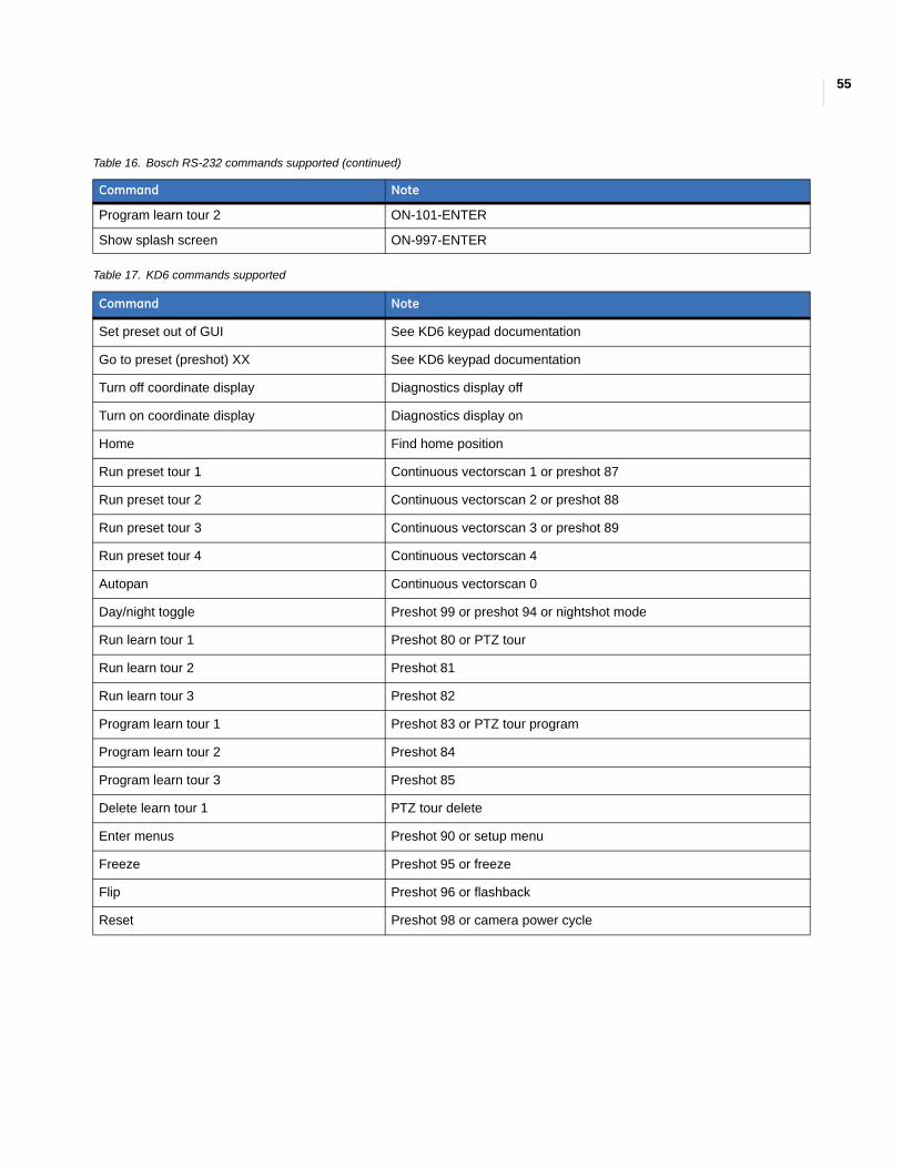
55
Program learn tour 2 ON-101-ENTER
Show splash screen ON-997-ENTER
Table 17. KD6 commands supported
Command Note
Set preset out of GUI See KD6 keypad documentation
Go to preset (preshot) XX See KD6 keypad documentation
Turn off coordinate display Diagnostics display off
Turn on coordinate display Diagnostics display on
Home Find home position
Run preset tour 1 Continuous vectorscan 1 or preshot 87
Run preset tour 2 Continuous vectorscan 2 or preshot 88
Run preset tour 3 Continuous vectorscan 3 or preshot 89
Run preset tour 4 Continuous vectorscan 4
Autopan Continuous vectorscan 0
Day/night toggle Preshot 99 or preshot 94 or nightshot mode
Run learn tour 1 Preshot 80 or PTZ tour
Run learn tour 2 Preshot 81
Run learn tour 3 Preshot 82
Program learn tour 1 Preshot 83 or PTZ tour program
Program learn tour 2 Preshot 84
Program learn tour 3 Preshot 85
Delete learn tour 1 PTZ tour delete
Enter menus Preshot 90 or setup menu
Freeze Preshot 95 or freeze
Flip Preshot 96 or flashback
Reset Preshot 98 or camera power cycle
Table 16. Bosch RS-232 commands supported (continued)
Command Note
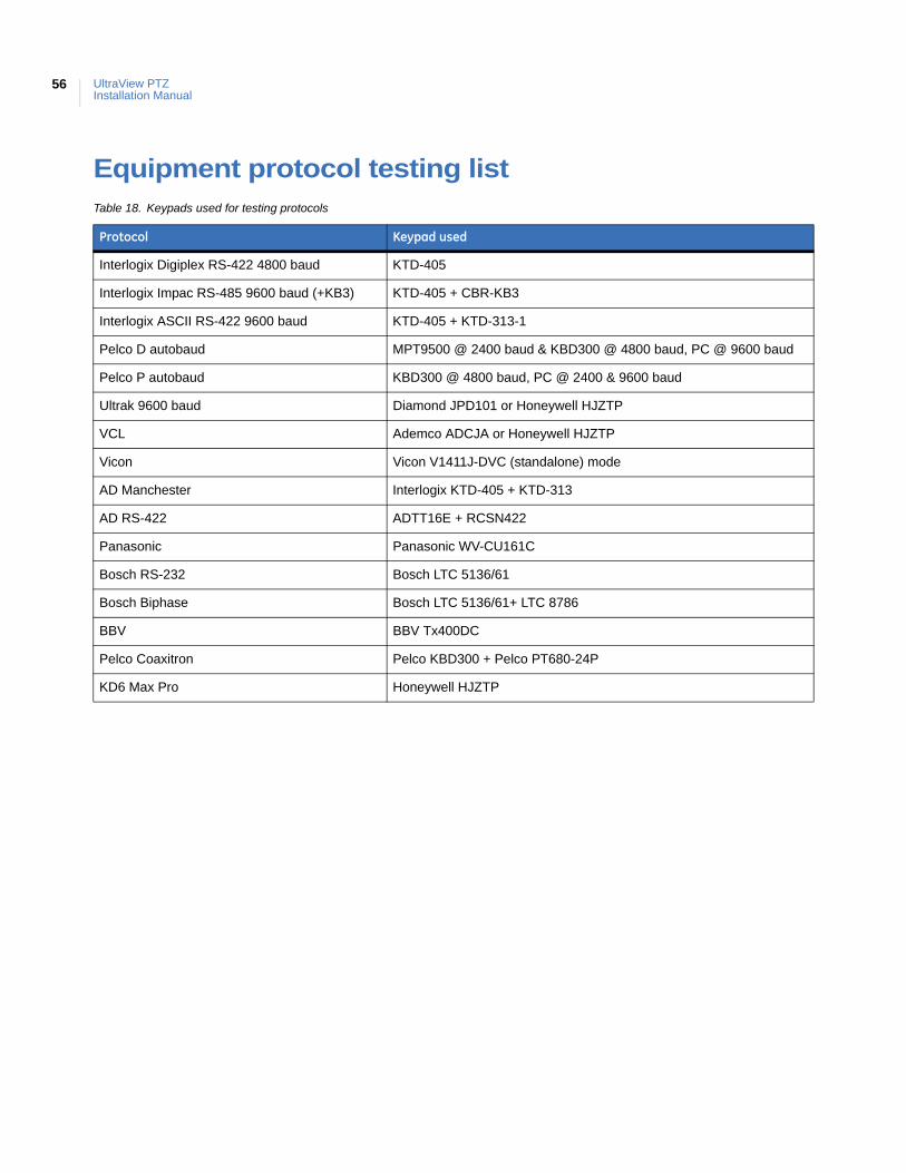
UltraView PTZInstallation Manual
56
Equipment protocol testing listTable 18. Keypads used for testing protocols
Protocol Keypad used
Interlogix Digiplex RS-422 4800 baud KTD-405
Interlogix Impac RS-485 9600 baud (+KB3) KTD-405 + CBR-KB3
Interlogix ASCII RS-422 9600 baud KTD-405 + KTD-313-1
Pelco D autobaud MPT9500 @ 2400 baud & KBD300 @ 4800 baud, PC @ 9600 baud
Pelco P autobaud KBD300 @ 4800 baud, PC @ 2400 & 9600 baud
Ultrak 9600 baud Diamond JPD101 or Honeywell HJZTP
VCL Ademco ADCJA or Honeywell HJZTP
Vicon Vicon V1411J-DVC (standalone) mode
AD Manchester Interlogix KTD-405 + KTD-313
AD RS-422 ADTT16E + RCSN422
Panasonic Panasonic WV-CU161C
Bosch RS-232 Bosch LTC 5136/61
Bosch Biphase Bosch LTC 5136/61+ LTC 8786
BBV BBV Tx400DC
Pelco Coaxitron Pelco KBD300 + Pelco PT680-24P
KD6 Max Pro Honeywell HJZTP
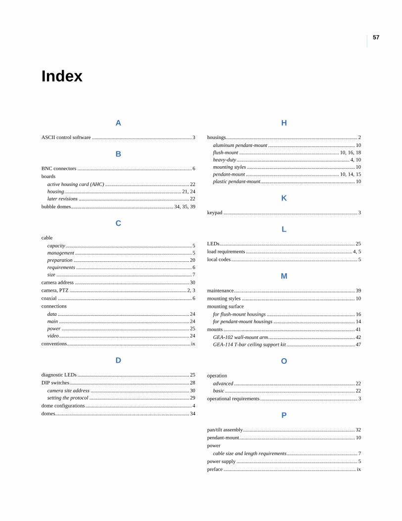
57
Index
A
ASCII control software ............................................................................ 3
B
BNC connectors ....................................................................................... 6
boards
active housing card (AHC) ................................................................ 22housing ......................................................................................... 21, 24later revisions .................................................................................... 22
bubble domes.............................................................................. 34, 35, 39
C
cable
capacity ................................................................................................ 5management ......................................................................................... 5preparation ........................................................................................ 20requirements ........................................................................................ 6size ....................................................................................................... 7
camera address ....................................................................................... 30
camera, PTZ ......................................................................................... 2, 3
coaxial ...................................................................................................... 6
connections
data .................................................................................................... 24main ................................................................................................... 24power ................................................................................................. 25video ................................................................................................... 24
conventions.............................................................................................. ix
D
diagnostic LEDs ..................................................................................... 25
DIP switches........................................................................................... 28
camera site address ........................................................................... 30setting the protocol ............................................................................ 29
dome configurations ................................................................................. 4
domes...................................................................................................... 34
H
housings.................................................................................................... 2
aluminum pendant-mount .................................................................. 10flush-mount ............................................................................ 10, 16, 18heavy-duty ...................................................................................... 4, 10mounting styles .................................................................................. 10pendant-mount ....................................................................... 10, 14, 15plastic pendant-mount........................................................................ 10
K
keypad ...................................................................................................... 3
L
LEDs....................................................................................................... 25
load requirements ................................................................................. 4, 5
local codes ................................................................................................ 5
M
maintenance............................................................................................ 39
mounting styles ...................................................................................... 10
mounting surface
for flush-mount housings ................................................................... 16for pendant-mount housings .............................................................. 14
mounts .................................................................................................... 41
GEA-102 wall-mount arm.................................................................. 42GEA-114 T-bar ceiling support kit .................................................... 47
O
operation
advanced ............................................................................................ 22basic ................................................................................................... 22
operational requirements .......................................................................... 3
P
pan/tilt assembly..................................................................................... 32
pendant-mount........................................................................................ 10
power
cable size and length requirements...................................................... 7
power supply ............................................................................................ 5
preface ..................................................................................................... ix
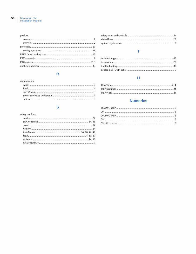
UltraView PTZInstallation Manual
58
product
contents ................................................................................................ 2overview ............................................................................................... 2
protocols ................................................................................................. 29
setting a protocol ............................................................................... 29
PTFE thread sealing tape........................................................................ 15
PTZ assembly ........................................................................................... 2
PTZ camera .......................................................................................... 2, 3
publication library .................................................................................. 40
R
requirements
cable ..................................................................................................... 6load ...................................................................................................... 4operational ........................................................................................... 3power cable size and length ................................................................. 7system ................................................................................................... 3
S
safety cautions
cables ................................................................................................. 24captive screws .............................................................................. 34, 35dome ................................................................................................... 34heaters................................................................................................ 24installation ....................................................................... 14, 16, 42, 47load .......................................................................................... 4, 15, 17moisture ....................................................................................... 14, 16power supplies ..................................................................................... 5
safety terms and symbols ........................................................................ ix
site address ............................................................................................. 28
system requirements ................................................................................. 3
T
technical support .................................................................................... 40
termination ............................................................................................. 26
troubleshooting....................................................................................... 38
twisted-pair (UTP) cable .......................................................................... 6
U
UltraView ............................................................................................. 2, 4
UTP terminals ........................................................................................ 24
UTP video .............................................................................................. 24
Numerics
16 AWG UTP........................................................................................... 6
20.............................................................................................................. 6
20 AWG UTP........................................................................................... 6
59U ........................................................................................................... 6
59U/6U coaxial ........................................................................................ 6