Ultraspin Oil Skimmer Products Skimmers: S1, S2 & … · Ultraspin Skimmers are able to collect all...
22
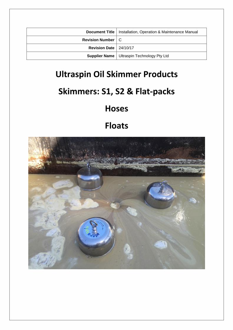
Document Title Installation, Operation & Maintenance Manual Revision Number C Revision Date 24/10/17 Supplier Name Ultraspin Technology Pty Ltd Ultraspin Oil Skimmer Products Skimmers: S1, S2 & Flat-packs Hoses Floats
Transcript of Ultraspin Oil Skimmer Products Skimmers: S1, S2 & … · Ultraspin Skimmers are able to collect all...
Document Title Installation, Operation & Maintenance Manual
Revision Number C
Revision Date 24/10/17
Supplier Name Ultraspin Technology Pty Ltd
Ultraspin Oil Skimmer Products
Skimmers: S1, S2 & Flat-packs
Hoses
Floats
ULTRASPIN OIL SKIMMERS
INSTALLATION, OPERATING AND MAINTENANCE MANUAL
Page 2 of 19
Table of Contents Table of Contents ............................................................................................................................... 2
1. System Overview............................................................................................................................. 4
1.1 Description .............................................................................................................................. 4
1.2 Skimmer Features ................................................................................................................... 5
1.3 How does it work? .................................................................................................................. 5
2. Assembly ......................................................................................................................................... 6
2.1 Assembly of the S1 Skimmer ................................................................................................... 6
2.2 Assembly of the S2 Skimmer ................................................................................................... 8
2.3 Assembly of the Trash Screen (Optional) .............................................................................. 10
3. Installation of the Oil Skimmers .................................................................................................... 12
4. Maintenance and Servicing ........................................................................................................... 13
4.1 Minor Service: Inspect and clean .......................................................................................... 13
4.2 Major Service: Replace skimmer internals............................................................................ 13
5. Skimmer Spare Parts ..................................................................................................................... 14
6. Specifications ................................................................................................................................ 14
7. Troubleshooting Guide ................................................................................................................. 15
8. Appendices .................................................................................................................................... 16

ULTRASPIN OIL SKIMMERS
INSTALLATION, OPERATING AND MAINTENANCE MANUAL
Page 3 of 19
Important Notes to Read Before Commencing any Work
Safety
Before attempting to undertake installation, maintenance or repair work of any nature, the persons concerned should be alerted to the nature of the risks involved when working in a situation of a potentially hazardous nature. As it is not possible to cover every aspect of safety in a single article, care has been taken in preparation of the following notes, which should serve as a general guide to the most common situations likely to be encountered. It is necessary to point out that Ultraspin or any of its associates cannot accept responsibility for any form of personal injury, however caused. Therefore, every care should be taken to observe the normal rules of safety.
Approvals
The manual is intended as a guide only. If required, site-specific drawings, Council, Water, Electricity Authority and Government approval and professional advice shall be obtained prior to installing the equipment mentioned in this manual.
Warning Certain instructions and advice carry this tag. This information should NOT be ignored or damage to equipment or personnel could result.
Warranty
The data is based on tests and experience which Ultraspin Technology Pty Ltd believe reliable and is supplied for information services only. Ultraspin Technology Pty Ltd disclaims any liability for damage or injury which results from the use of the enclosed data and nothing contained therein shall constitute a guarantee, warranty or representation (including free from patent liability) by Ultraspin Technology Pty Ltd with respect to the data, the product described, or its suitability for any specific purpose, even if that purpose is known to Ultraspin Technology Pty Ltd.
Patents
Ultraspin Technology Pty Ltd has patented features of the skimmer, hydrocyclone and processes covered in this literature. Processes or products in this manual should not be used without the prior written consent of Ultraspin Technology Pty Ltd.
Update Data subject to correction and update without notice
Copyright Ultraspin Technology Pty Ltd © 2010-2017; All rights reserved
Standards
This Ultraspin Separators are designed to comply with some or all of the following standards: NSW Land & Water Conservation, January 1997 Guidelines for the On-Site Treatment of Trade Waste Discharge to Sewer AS/NZS 4494:1998 Discharge of Commercial & Industrial Liquid Waste to Sewer – General Performance Requirements National Water Quality Management Guideline for Sewerage Systems, November 1998 A list of manufacturing standards is available on request.
Design
This manual is not a design guide. It does not provide a substitute for careful planning and a considered site design drawing prepared by qualified and experienced people. If there is any uncertainty with design the service of competent design engineers experienced in oily water and local requirements should be sought. If needed Ultraspin can provide a list of recommended designers.
ULTRASPIN OIL SKIMMERS
INSTALLATION, OPERATING AND MAINTENANCE MANUAL
Page 4 of 19
1. System Overview
1.1 Description Skimmers are designed to remove oil, fats and floating material from tanks, pits and open waters. Ultraspin skimmers are true self-adjusting, weir-type, oily water skimmers and are an important part of oily water treatment systems.
IMPORTANT: No type or brand of oil skimmer is a water treatment device. Removing oil on the surface does not treat the water below. If your primary problem is cleaning the water, then water treatment equipment is needed.
1.1.1 Oil Recovery
After the skimming process it may be necessary to drain the excess water and collect concentrated oil. For this purpose, Ultraspin is able to provide the Oil Recovery System (ORS). These packaged systems include a pump, skimmer, hose and collection tank which automatically decants water back to your collection pit.
1.1.2 Water Treatment Systems
Ultraspin Skimmers are able to collect all contents of an oily water pit or tank regardless of oil composition and the addition of surfactants. They do not distinguish between fluid types and therefore do not treat the water. The skimmers can be used in conjunction with Ultraspin Water treatment systems capable of improving water quality through their unique water treatment process.
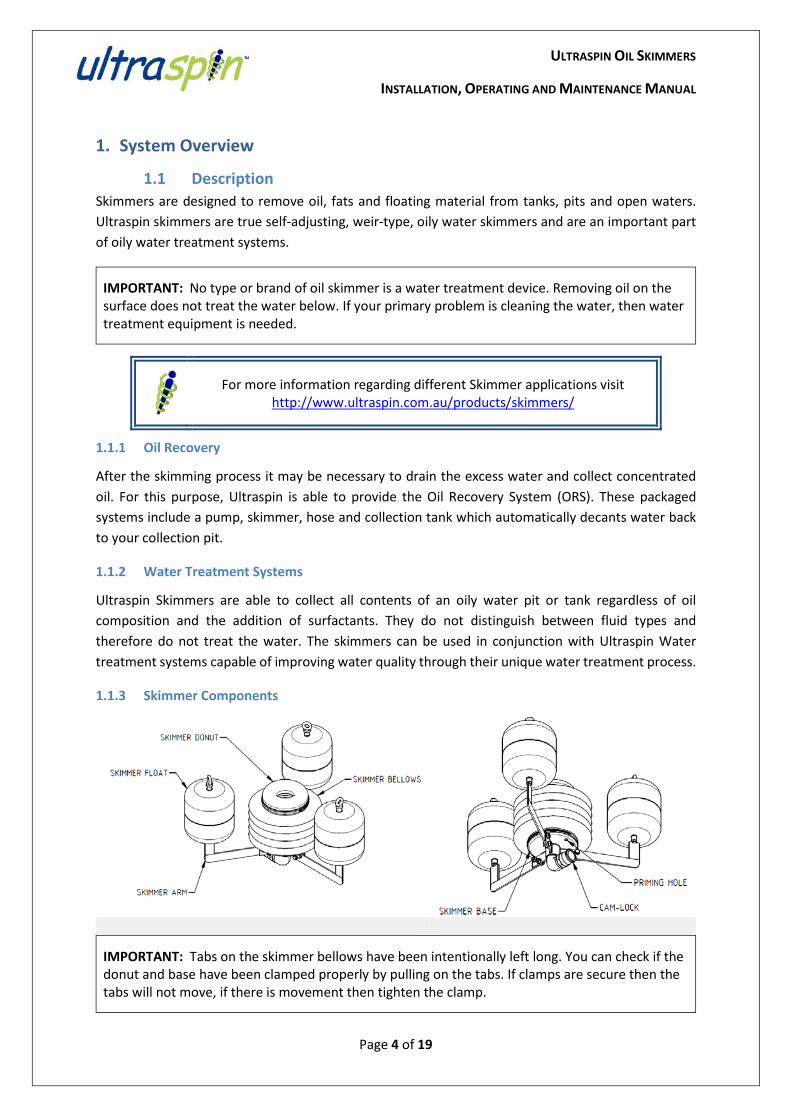
1.1.3 Skimmer Components
IMPORTANT: Tabs on the skimmer bellows have been intentionally left long. You can check if the donut and base have been clamped properly by pulling on the tabs. If clamps are secure then the tabs will not move, if there is movement then tighten the clamp.
For more information regarding different Skimmer applications visit
http://www.ultraspin.com.au/products/skimmers/
ULTRASPIN OIL SKIMMERS
INSTALLATION, OPERATING AND MAINTENANCE MANUAL
Page 5 of 19
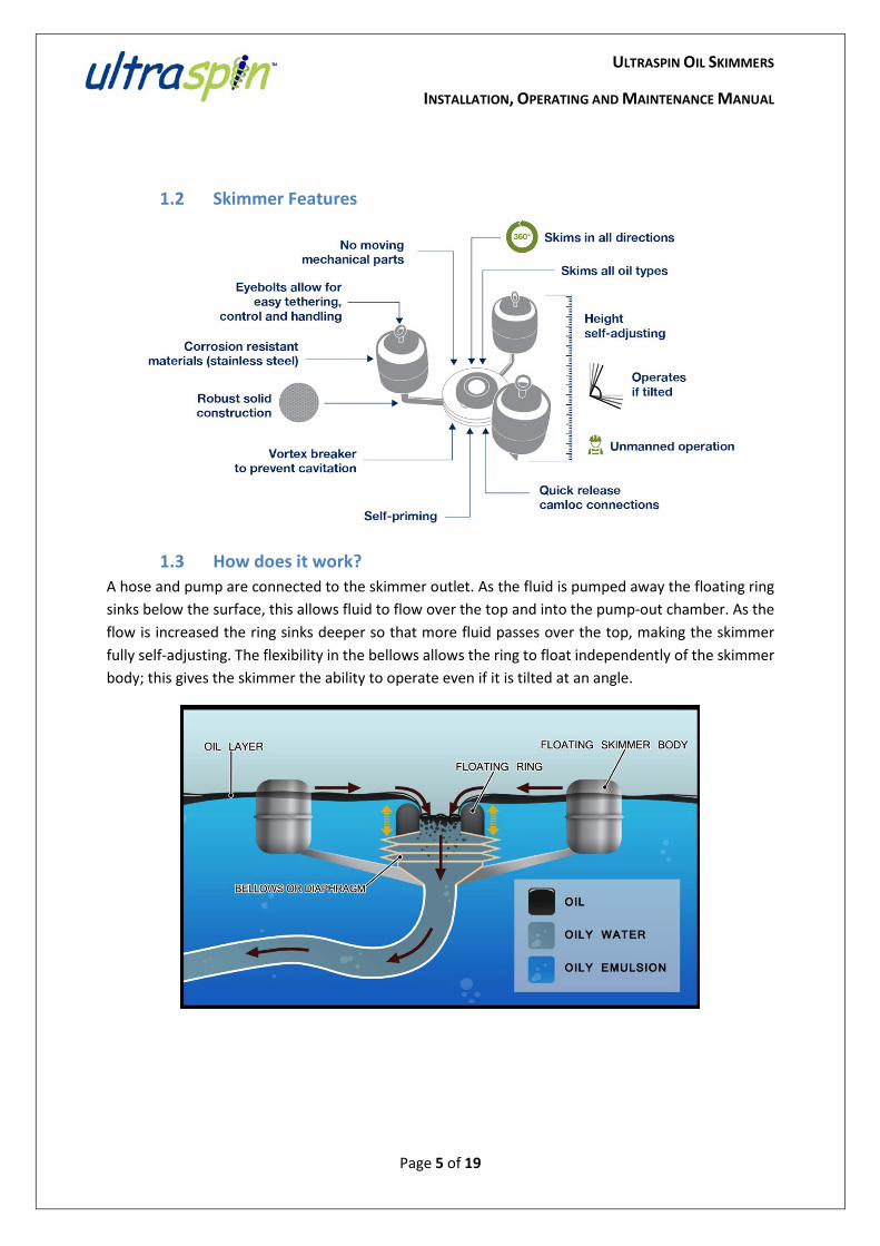
1.2 Skimmer Features
1.3 How does it work? A hose and pump are connected to the skimmer outlet. As the fluid is pumped away the floating ring sinks below the surface, this allows fluid to flow over the top and into the pump-out chamber. As the flow is increased the ring sinks deeper so that more fluid passes over the top, making the skimmer fully self-adjusting. The flexibility in the bellows allows the ring to float independently of the skimmer body; this gives the skimmer the ability to operate even if it is tilted at an angle.

ULTRASPIN OIL SKIMMERS
INSTALLATION, OPERATING AND MAINTENANCE MANUAL
Page 6 of 19
2. Assembly
Assembly of skimmer is only required if skimmer flat-pack is purchased. If assembly is required, please follow the assembly instructions for the skimmer model purchased.
2.1 Assembly of the S1 Skimmer
2.1.1 Ultraspin Supplied Components
2.1.2 Items Required
Quantity • 17mm ring spanner 2 • Thread locking paste (Locktite 243) -
To check out our skimmers in action, watch our video at
http://www.ultraspin.com.au/index.php/products/oil-skimmer
ULTRASPIN OIL SKIMMERS
INSTALLATION, OPERATING AND MAINTENANCE MANUAL
Page 7 of 19
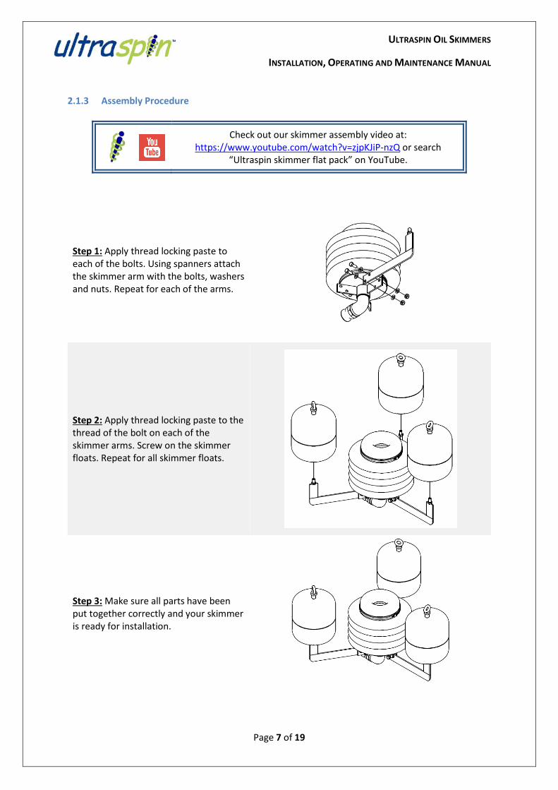
2.1.3 Assembly Procedure
Step 1: Apply thread locking paste to each of the bolts. Using spanners attach the skimmer arm with the bolts, washers and nuts. Repeat for each of the arms.
Step 2: Apply thread locking paste to the thread of the bolt on each of the skimmer arms. Screw on the skimmer floats. Repeat for all skimmer floats.
Step 3: Make sure all parts have been put together correctly and your skimmer is ready for installation.
Check out our skimmer assembly video at: https://www.youtube.com/watch?v=zjpKJiP-nzQ or search
“Ultraspin skimmer flat pack” on YouTube.
ULTRASPIN OIL SKIMMERS
INSTALLATION, OPERATING AND MAINTENANCE MANUAL
Page 8 of 19
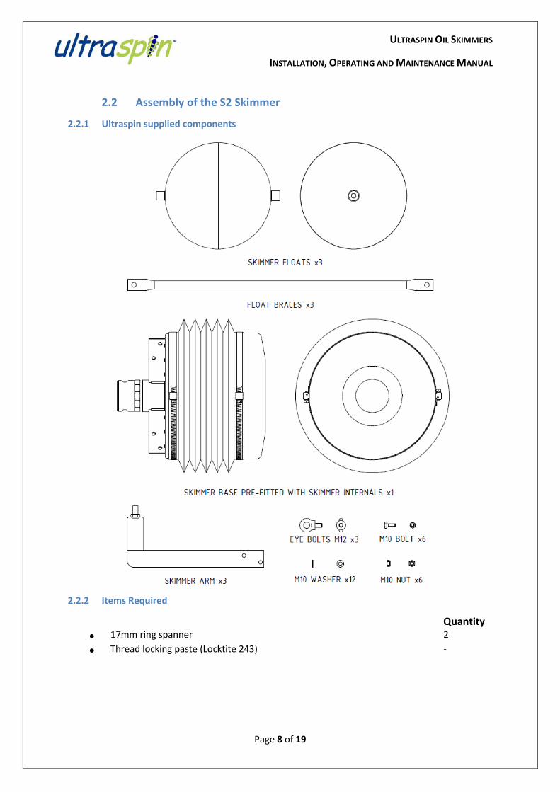
2.2 Assembly of the S2 Skimmer
2.2.1 Ultraspin supplied components
2.2.2 Items Required
Quantity • 17mm ring spanner 2 • Thread locking paste (Locktite 243) -
ULTRASPIN OIL SKIMMERS
INSTALLATION, OPERATING AND MAINTENANCE MANUAL
Page 9 of 19
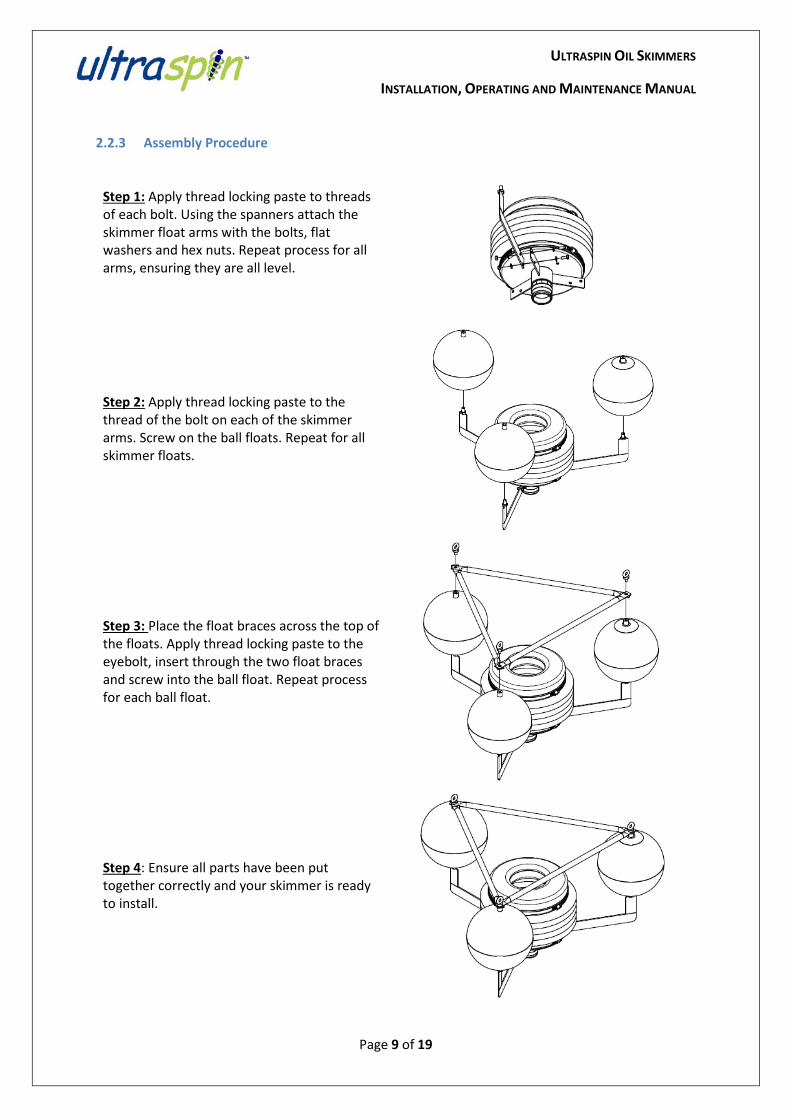
2.2.3 Assembly Procedure
Step 1: Apply thread locking paste to threads of each bolt. Using the spanners attach the skimmer float arms with the bolts, flat washers and hex nuts. Repeat process for all arms, ensuring they are all level.
Step 2: Apply thread locking paste to the thread of the bolt on each of the skimmer arms. Screw on the ball floats. Repeat for all skimmer floats.
Step 3: Place the float braces across the top of the floats. Apply thread locking paste to the eyebolt, insert through the two float braces and screw into the ball float. Repeat process for each ball float.
Step 4: Ensure all parts have been put together correctly and your skimmer is ready to install.
ULTRASPIN OIL SKIMMERS
INSTALLATION, OPERATING AND MAINTENANCE MANUAL
Page 10 of 19
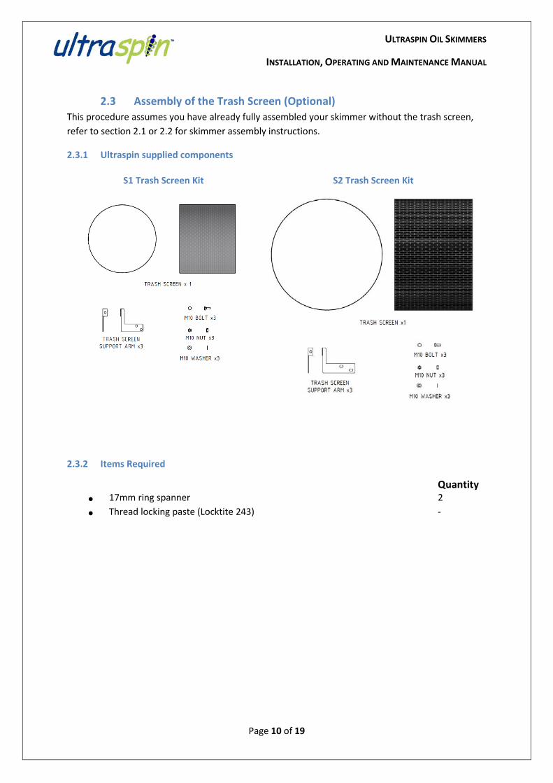
2.3 Assembly of the Trash Screen (Optional) This procedure assumes you have already fully assembled your skimmer without the trash screen, refer to section 2.1 or 2.2 for skimmer assembly instructions.
2.3.1 Ultraspin supplied components
S1 Trash Screen Kit S2 Trash Screen Kit
2.3.2 Items Required
Quantity • 17mm ring spanner 2 • Thread locking paste (Locktite 243) -
ULTRASPIN OIL SKIMMERS
INSTALLATION, OPERATING AND MAINTENANCE MANUAL
Page 11 of 19
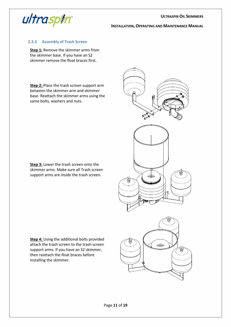
2.3.3 Assembly of Trash Screen
Step 1: Remove the skimmer arms from the skimmer base. If you have an S2 skimmer remove the float braces first.
Step 2: Place the trash screen support arm between the skimmer arm and skimmer base. Reattach the skimmer arms using the same bolts, washers and nuts.
Step 3: Lower the trash screen onto the skimmer arms. Make sure all Trash screen support arms are inside the trash screen.
Step 4: Using the additional bolts provided attach the trash screen to the trash screen support arms. If you have an S2 skimmer, then reattach the float braces before installing the skimmer.
ULTRASPIN OIL SKIMMERS
INSTALLATION, OPERATING AND MAINTENANCE MANUAL
Page 12 of 19
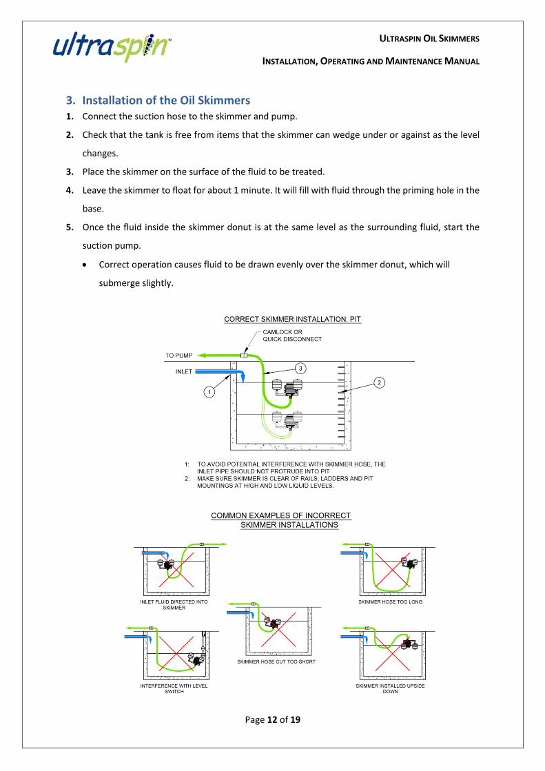
3. Installation of the Oil Skimmers 1. Connect the suction hose to the skimmer and pump.
2. Check that the tank is free from items that the skimmer can wedge under or against as the level
changes.
3. Place the skimmer on the surface of the fluid to be treated.
4. Leave the skimmer to float for about 1 minute. It will fill with fluid through the priming hole in the
base.
5. Once the fluid inside the skimmer donut is at the same level as the surrounding fluid, start the
suction pump.
• Correct operation causes fluid to be drawn evenly over the skimmer donut, which will
submerge slightly.
ULTRASPIN OIL SKIMMERS
INSTALLATION, OPERATING AND MAINTENANCE MANUAL
Page 13 of 19
4. Maintenance and Servicing
4.1 Minor Service: Inspect and clean Frequency: every 6 months
4.1.1 Order Parts
No spare parts are required for the Minor Service on an Ultraspin Skimmer unless components are damaged. If items are damaged and need replacing, please see Appendix 1 for Spare Parts List.
4.1.2 Typical Items Required
• No items required
4.1.3 Service Procedure
1. Carefully remove skimmer from the tank or pit. 2. Disconnect suction hose. 3. Wash off built up trash or sediment using a low-pressure clean water hose, taking care not
to damage the bellows. 4. Check for and remove any blockages in the skimmer base hose connection and priming hole. 5. Return the skimmer to the tank or pit as per Section 3. 6. If any components are damaged, then replace them.
4.2 Major Service: Replace skimmer internals Frequency: every 3 years
4.2.1 Order Parts
Please refer to Appendix 1 for spare parts that must be replaced as part of the Major Service.
4.2.2 Typical Items Required
• Flat head screwdriver
4.2.3 Service Procedure
1. Carefully remove skimmer from the tank or pit. 2. Disconnect suction hose. 3. Use the screwdriver to loosen the clamp around the skimmer base. 4. Remove the skimmer internals from the base and dispose. 5. Attach the new internals to the base. 6. Fit the clamp around the bellows and base and tighten using the screwdriver. 7. Ensure that the bellows are able to move up and down freely. 8. Return the skimmer to the tank or pit as per Section 3.
ULTRASPIN OIL SKIMMERS
INSTALLATION, OPERATING AND MAINTENANCE MANUAL
Page 14 of 19
5. Skimmer Spare Parts
For the Spare Parts List for the Ultraspin Skimmers, please refer to Appendix 1.
6. Specifications
For specifications on the Ultraspin Oil Skimmers and options, including materials, dimensions and flowrates, please refer to Appendix 2.
To order spare parts, please contact Ultraspin on +61 3 8841 7200 or email [email protected]
ULTRASPIN OIL SKIMMERS
INSTALLATION, OPERATING AND MAINTENANCE MANUAL
Page 15 of 19
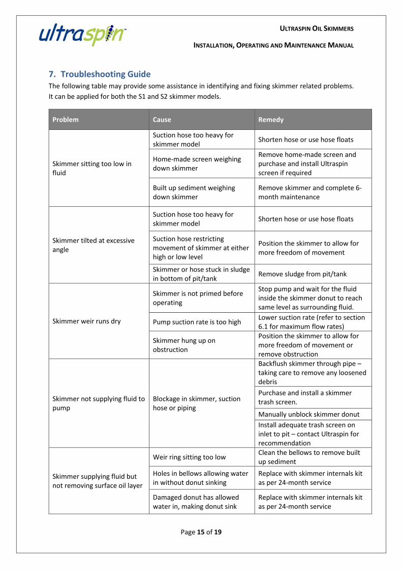
7. Troubleshooting Guide The following table may provide some assistance in identifying and fixing skimmer related problems. It can be applied for both the S1 and S2 skimmer models.
Problem Cause Remedy
Skimmer sitting too low in fluid
Suction hose too heavy for skimmer model Shorten hose or use hose floats
Home-made screen weighing down skimmer
Remove home-made screen and purchase and install Ultraspin screen if required
Built up sediment weighing down skimmer
Remove skimmer and complete 6-month maintenance
Skimmer tilted at excessive angle
Suction hose too heavy for skimmer model Shorten hose or use hose floats
Suction hose restricting movement of skimmer at either high or low level
Position the skimmer to allow for more freedom of movement
Skimmer or hose stuck in sludge in bottom of pit/tank Remove sludge from pit/tank
Skimmer weir runs dry
Skimmer is not primed before operating
Stop pump and wait for the fluid inside the skimmer donut to reach same level as surrounding fluid.
Pump suction rate is too high Lower suction rate (refer to section 6.1 for maximum flow rates)
Skimmer hung up on obstruction
Position the skimmer to allow for more freedom of movement or remove obstruction
Skimmer not supplying fluid to pump
Blockage in skimmer, suction hose or piping
Backflush skimmer through pipe – taking care to remove any loosened debris Purchase and install a skimmer trash screen.
Manually unblock skimmer donut Install adequate trash screen on inlet to pit – contact Ultraspin for recommendation
Skimmer supplying fluid but not removing surface oil layer
Weir ring sitting too low Clean the bellows to remove built up sediment
Holes in bellows allowing water in without donut sinking
Replace with skimmer internals kit as per 24-month service
Damaged donut has allowed water in, making donut sink
Replace with skimmer internals kit as per 24-month service

ULTRASPIN OIL SKIMMERS
INSTALLATION, OPERATING AND MAINTENANCE MANUAL
Page 16 of 19
8. Appendices
• Appendix 1 – Spare Parts List: Ultraspin Oil Skimmer
• Appendix 2 – Drawings and Specifications
A. I-S-0040-01 – S1 Skimmer and Options
B. I-S-0050-01 – S2 Skimmer and Options
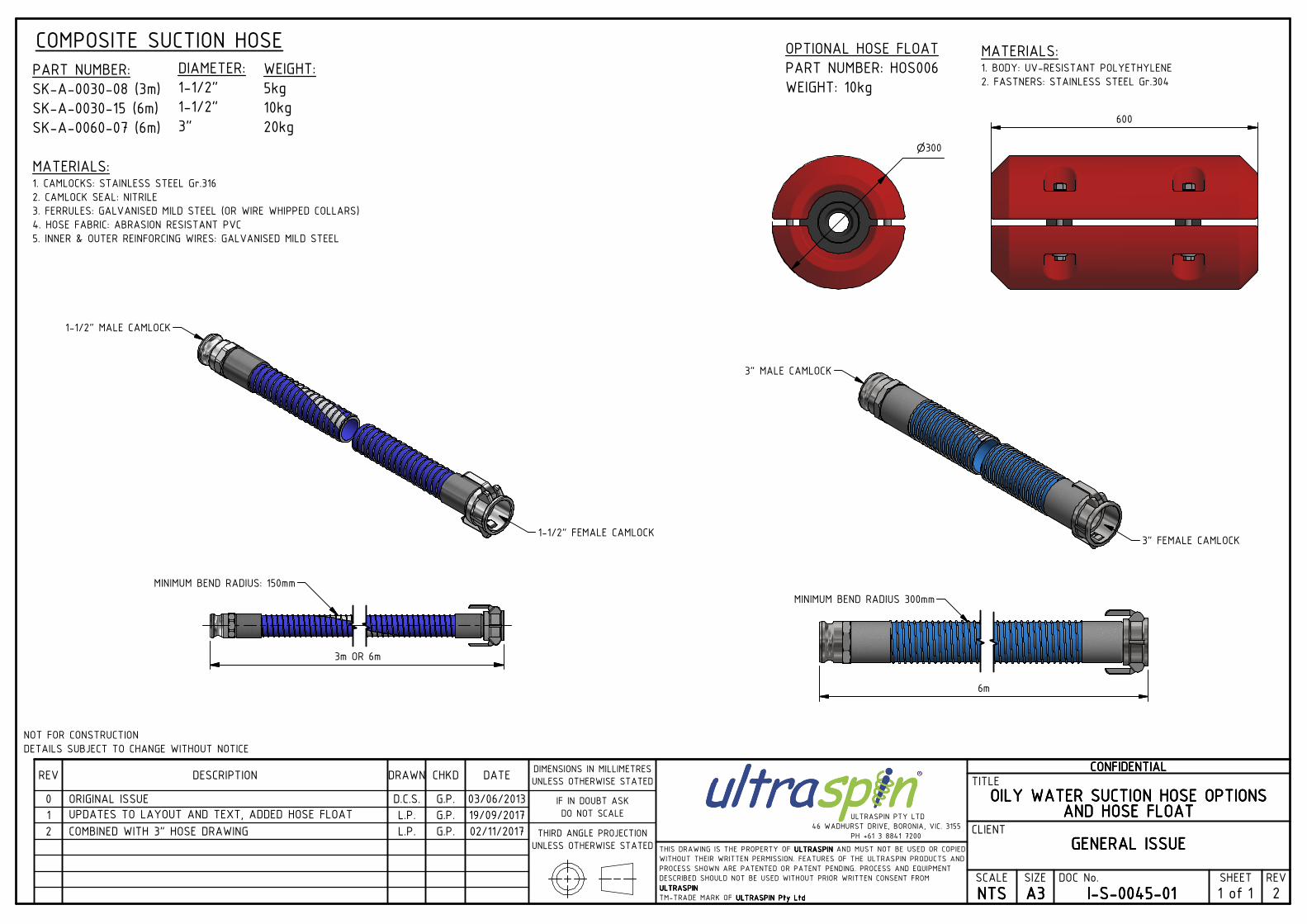
C. I-S-0045-01 – Oily Water Suction Hose Options and Hose Float
ULTRASPIN OIL SKIMMERS
INSTALLATION, OPERATING AND MAINTENANCE MANUAL
Page 17 of 19
Appendix 1: Skimmer Spare Parts List
U:\Service, Spares and Warranty\Spares\Spare Parts List\Skimmer Spare Parts List (Rev 0)
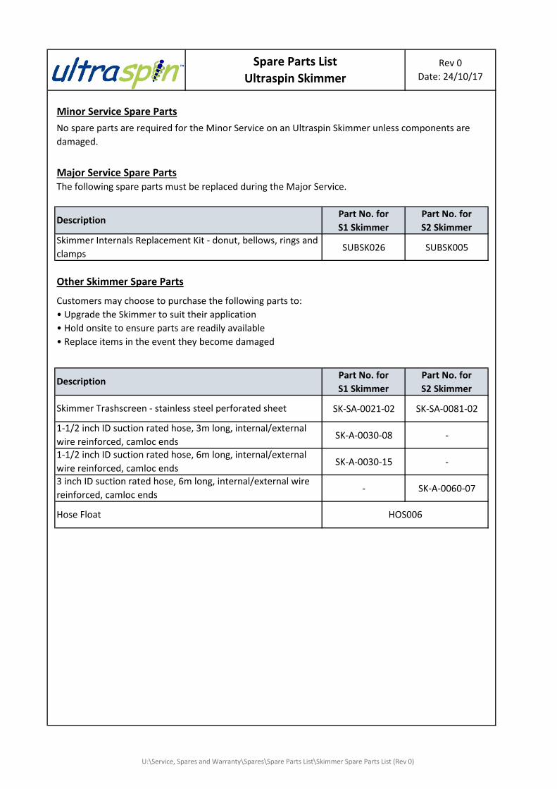
Minor Service Spare Parts
Major Service Spare PartsThe following spare parts must be replaced during the Major Service.
Part No. for S1 Skimmer
Part No. for S2 Skimmer
SUBSK026 SUBSK005
Other Skimmer Spare Parts
Part No. for S1 Skimmer
Part No. for S2 Skimmer
SK-SA-0021-02 SK-SA-0081-02
SK-A-0030-08 -
SK-A-0030-15 -
- SK-A-0060-073 inch ID suction rated hose, 6m long, internal/external wire reinforced, camloc ends
Hose Float HOS006
Customers may choose to purchase the following parts to:• Upgrade the Skimmer to suit their application• Hold onsite to ensure parts are readily available• Replace items in the event they become damaged
Skimmer Trashscreen - stainless steel perforated sheet
Description
1-1/2 inch ID suction rated hose, 3m long, internal/external wire reinforced, camloc ends1-1/2 inch ID suction rated hose, 6m long, internal/external wire reinforced, camloc ends
Spare Parts ListUltraspin Skimmer
Skimmer Internals Replacement Kit - donut, bellows, rings and clamps
Description
No spare parts are required for the Minor Service on an Ultraspin Skimmer unless components are damaged.
Rev 0Date: 24/10/17
ULTRASPIN OIL SKIMMERS
INSTALLATION, OPERATING AND MAINTENANCE MANUAL
Page 18 of 19
Appendix 2: Drawings and Specifications
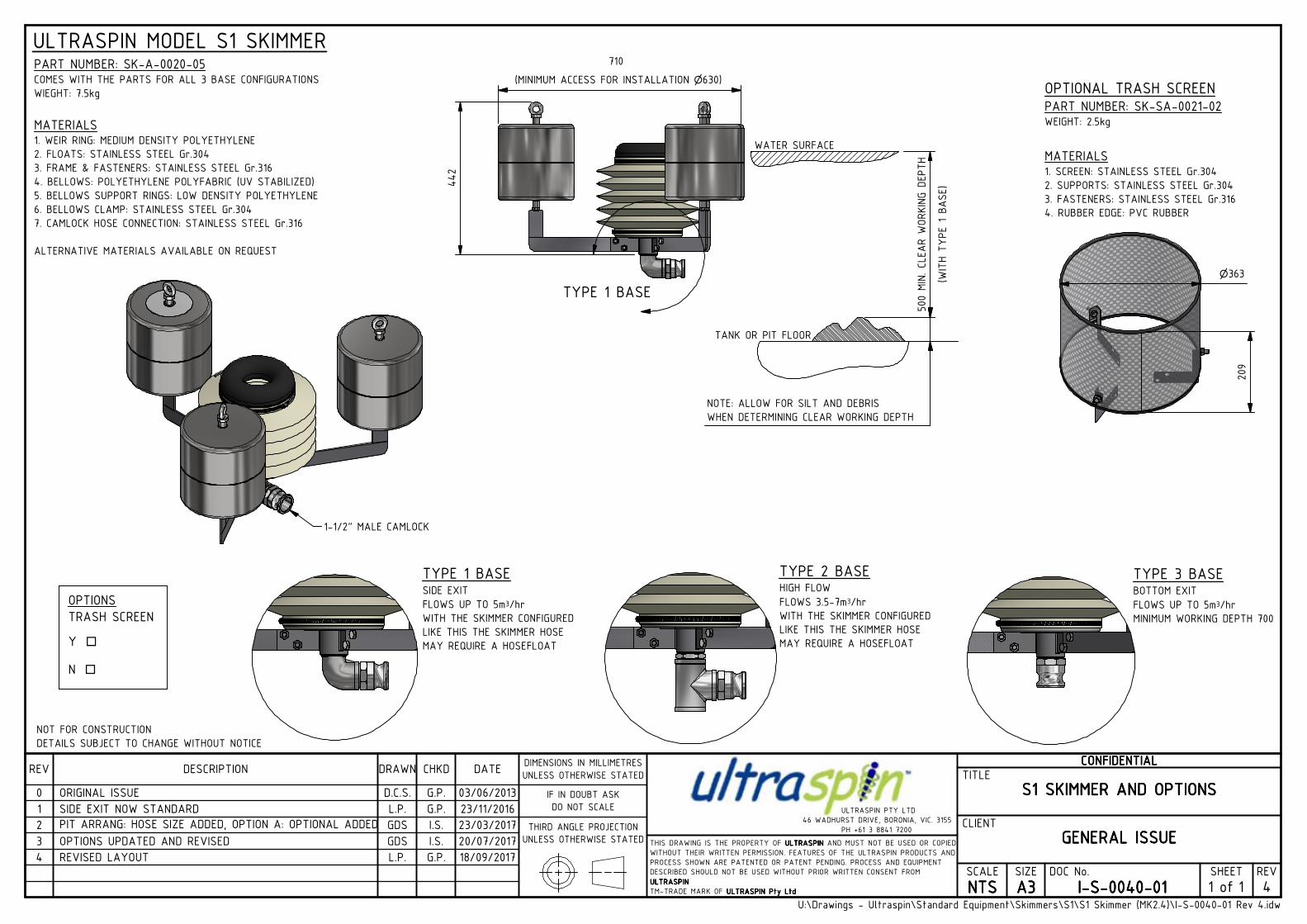
TYPE 1 BASESIDE EXIT
FLOWS UP TO 5m3/hr
WITH THE SKIMMER CONFIGURED
LIKE THIS THE SKIMMER HOSE
MAY REQUIRE A HOSEFLOAT
TYPE 2 BASEHIGH FLOW
FLOWS 3.5-7m3/hr
WITH THE SKIMMER CONFIGURED
LIKE THIS THE SKIMMER HOSE
MAY REQUIRE A HOSEFLOAT
TYPE 3 BASEBOTTOM EXIT
FLOWS UP TO 5m3/hr
MINIMUM WORKING DEPTH 700
U:\Drawings - Ultraspin\Standard Equipment\Skimmers\S1\S1 Skimmer (MK2.4)\I-S-0040-01 Rev 4.idw
CCCCOOOONNNNFFFFIIIIDDDDEEEENNNNTTTTIIIIAAAALLLLTITLE
CLIENT
SCALE
NNNNTTTTSSSSSIZE
AAAA3333DOC No.
IIII----SSSS----0000000044440000----00001111SHEET
1 REV
4
SSSS1111 SSSSKKKKIIIIMMMMMMMMEEEERRRR AAAANNNNDDDD OOOOPPPPTTTTIIIIOOOONNNNSSSS
GGGGEEEENNNNEEEERRRRAAAALLLL IIIISSSSSSSSUUUUEEEETHIS DRAWING IS THE PROPERTY OF UUUULLLLTTTTRRRRAAAASSSSPPPPIIIINNNN AND MUST NOT BE USED OR COPIED
WITHOUT THEIR WRITTEN PERMISSION. FEATURES OF THE ULTRASPIN PRODUCTS AND
PROCESS SHOWN ARE PATENTED OR PATENT PENDING. PROCESS AND EQUIPMENT
DESCRIBED SHOULD NOT BE USED WITHOUT PRIOR WRITTEN CONSENT FROM
UUUULLLLTTTTRRRRAAAASSSSPPPPIIIINNNN
TM-TRADE MARK OF UUUULLLLTTTTRRRRAAAASSSSPPPPIIIINNNN PPPPttttyyyy LLLLttttdddd
REV DESCRIPTION DRAWN CHKD DATE
0 ORIGINAL ISSUE D.C.S. G.P. 03/06/2013
DIMENSIONS IN MILLIMETRES
UNLESS OTHERWISE STATED
IF IN DOUBT ASK
DO NOT SCALE
THIRD ANGLE PROJECTION
UNLESS OTHERWISE STATED
ULTRASPIN PTY LTD
46 WADHURST DRIVE, BORONIA, VIC. 3155
PH +61 3 8841 7200 2 PIT ARRANG: HOSE SIZE ADDED, OPTION A: OPTIONAL ADDED GDS I.S. 23/03/2017
1 SIDE EXIT NOW STANDARD L.P. G.P. 23/11/2016
4 REVISED LAYOUT L.P. G.P. 18/09/2017
20/07/2017I.S.GDSOPTIONS UPDATED AND REVISED3
1 of
TYPE 1 BASE
TANK OR PIT FLOOR
WATER SURFACE
442
PART NUMBER: SK-A-0020-05COMES WITH THE PARTS FOR ALL 3 BASE CONFIGURATIONS
WIEGHT: 7.5kg
MATERIALS1. WEIR RING: MEDIUM DENSITY POLYETHYLENE
2. FLOATS: STAINLESS STEEL Gr.304
3. FRAME & FASTENERS: STAINLESS STEEL Gr.316
4. BELLOWS: POLYETHYLENE POLYFABRIC (UV STABILIZED)
5. BELLOWS SUPPORT RINGS: LOW DENSITY POLYETHYLENE
6. BELLOWS CLAMP: STAINLESS STEEL Gr.304
7. CAMLOCK HOSE CONNECTION: STAINLESS STEEL Gr.316
ALTERNATIVE MATERIALS AVAILABLE ON REQUEST
ULTRASPIN MODEL S1 SKIMMER710
(MINIMUM ACCESS FOR INSTALLATION n630)
209
n363
500 MIN. CLEA
R W
ORKING D
EPTH
NOTE: ALLOW FOR SILT AND DEBRIS
WHEN DETERMINING CLEAR WORKING DEPTH
OPTIONAL TRASH SCREENPART NUMBER: SK-SA-0021-02WEIGHT: 2.5kg
MATERIALS1. SCREEN: STAINLESS STEEL Gr.304
2. SUPPORTS: STAINLESS STEEL Gr.304
3. FASTENERS: STAINLESS STEEL Gr.316
4. RUBBER EDGE: PVC RUBBER
OPTIONS
TRASH SCREEN
Y o
N o
1-1/2" MALE CAMLOCK
(WITH TYPE 1 B
ASE)
NOT FOR CONSTRUCTION
DETAILS SUBJECT TO CHANGE WITHOUT NOTICE
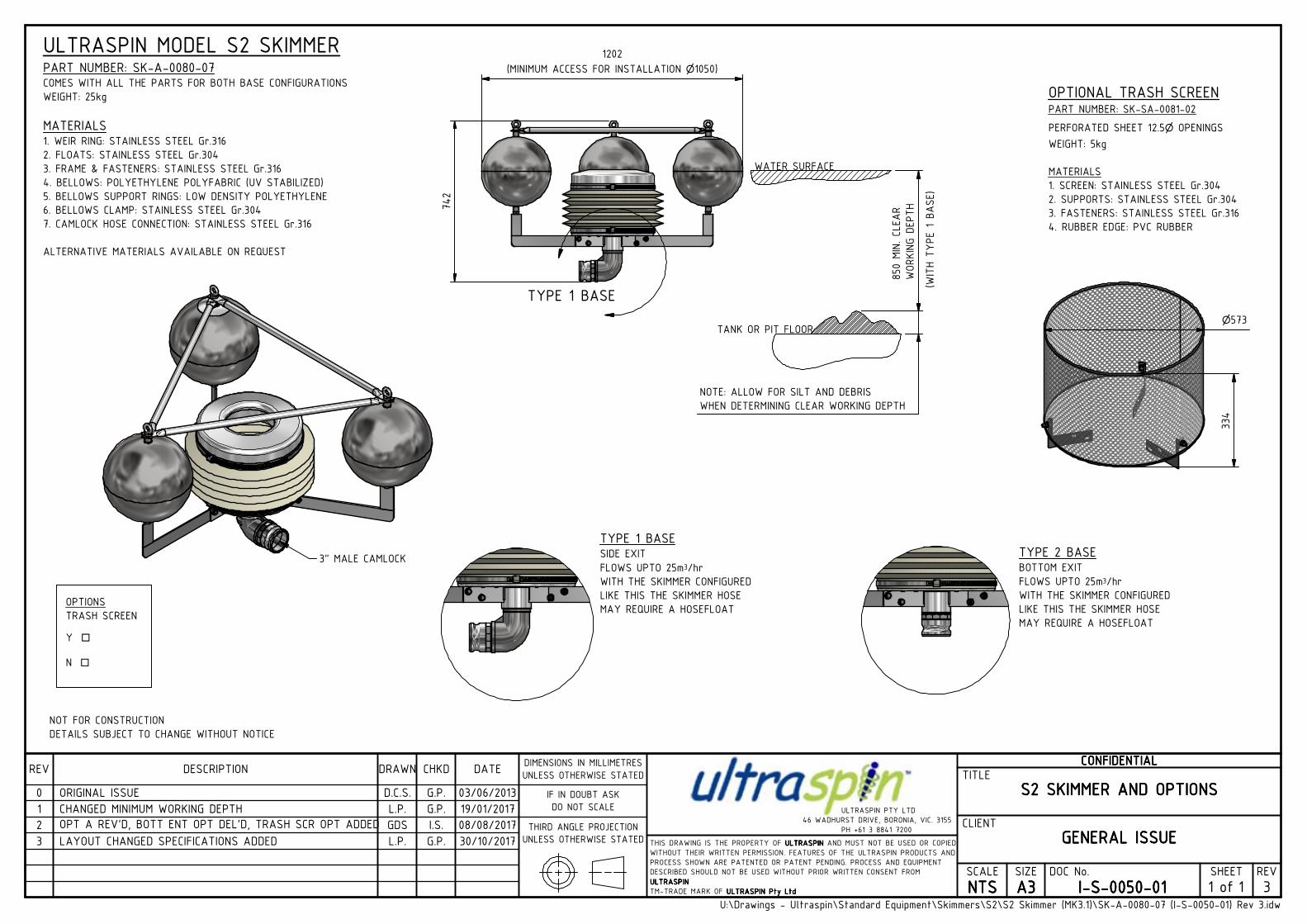
TYPE 1 BASESIDE EXIT
FLOWS UPTO 25m3/hr
WITH THE SKIMMER CONFIGURED
LIKE THIS THE SKIMMER HOSE
MAY REQUIRE A HOSEFLOAT
TYPE 2 BASEBOTTOM EXIT
FLOWS UPTO 25m3/hr
WITH THE SKIMMER CONFIGURED
LIKE THIS THE SKIMMER HOSE
MAY REQUIRE A HOSEFLOAT
U:\Drawings - Ultraspin\Standard Equipment\Skimmers\S2\S2 Skimmer (MK3.1)\SK-A-0080-07 (I-S-0050-01) Rev 3.idw
CCCCOOOONNNNFFFFIIIIDDDDEEEENNNNTTTTIIIIAAAALLLLTITLE
CLIENT
SCALE
NNNNTTTTSSSSSIZE
AAAA3333DOC No.
IIII----SSSS----0000000055550000----00001111SHEET
1 REV
3
SSSS2222 SSSSKKKKIIIIMMMMMMMMEEEERRRR AAAANNNNDDDD OOOOPPPPTTTTIIIIOOOONNNNSSSS
GGGGEEEENNNNEEEERRRRAAAALLLL IIIISSSSSSSSUUUUEEEETHIS DRAWING IS THE PROPERTY OF UUUULLLLTTTTRRRRAAAASSSSPPPPIIIINNNN AND MUST NOT BE USED OR COPIED
WITHOUT THEIR WRITTEN PERMISSION. FEATURES OF THE ULTRASPIN PRODUCTS AND
PROCESS SHOWN ARE PATENTED OR PATENT PENDING. PROCESS AND EQUIPMENT
DESCRIBED SHOULD NOT BE USED WITHOUT PRIOR WRITTEN CONSENT FROM
UUUULLLLTTTTRRRRAAAASSSSPPPPIIIINNNN
TM-TRADE MARK OF UUUULLLLTTTTRRRRAAAASSSSPPPPIIIINNNN PPPPttttyyyy LLLLttttdddd
REV DESCRIPTION DRAWN CHKD DATE
0 ORIGINAL ISSUE D.C.S. G.P. 03/06/2013
DIMENSIONS IN MILLIMETRES
UNLESS OTHERWISE STATED
IF IN DOUBT ASK
DO NOT SCALE
THIRD ANGLE PROJECTION
UNLESS OTHERWISE STATED
ULTRASPIN PTY LTD
46 WADHURST DRIVE, BORONIA, VIC. 3155
PH +61 3 8841 7200 2 OPT A REV'D, BOTT ENT OPT DEL'D, TRASH SCR OPT ADDED GDS I.S. 08/08/2017
1 CHANGED MINIMUM WORKING DEPTH L.P. G.P. 19/01/2017
30/10/2017G.P.L.P.LAYOUT CHANGED SPECIFICATIONS ADDED3
1 of
WATER SURFACE
TANK OR PIT FLOOR
TYPE 1 BASE
742
1202
(MINIMUM ACCESS FOR INSTALLATION n1050)
850 MIN. CLEAR
WORKING DEPTH
NOTE: ALLOW FOR SILT AND DEBRIS
WHEN DETERMINING CLEAR WORKING DEPTH
(WITH TYPE 1 BASE)
ULTRASPIN MODEL S2 SKIMMERPART NUMBER: SK-A-0080-07COMES WITH ALL THE PARTS FOR BOTH BASE CONFIGURATIONS
WEIGHT: 25kg
MATERIALS1. WEIR RING: STAINLESS STEEL Gr.316
2. FLOATS: STAINLESS STEEL Gr.304
3. FRAME & FASTENERS: STAINLESS STEEL Gr.316
4. BELLOWS: POLYETHYLENE POLYFABRIC (UV STABILIZED)
5. BELLOWS SUPPORT RINGS: LOW DENSITY POLYETHYLENE
6. BELLOWS CLAMP: STAINLESS STEEL Gr.304
7. CAMLOCK HOSE CONNECTION: STAINLESS STEEL Gr.316
ALTERNATIVE MATERIALS AVAILABLE ON REQUEST
NOT FOR CONSTRUCTION
DETAILS SUBJECT TO CHANGE WITHOUT NOTICE
OPTIONS
TRASH SCREEN
Y o
N o
n573
334
OPTIONAL TRASH SCREENPART NUMBER: SK-SA-0081-02
PERFORATED SHEET 12.5n OPENINGSWEIGHT: 5kg
MATERIALS
1. SCREEN: STAINLESS STEEL Gr.304
2. SUPPORTS: STAINLESS STEEL Gr.304
3. FASTENERS: STAINLESS STEEL Gr.316
4. RUBBER EDGE: PVC RUBBER
3" MALE CAMLOCK
CCCCOOOONNNNFFFFIIIIDDDDEEEENNNNTTTTIIIIAAAALLLLTITLE
CLIENT
SCALE
NNNNTTTTSSSSSIZE
AAAA3333DOC No.
IIII----SSSS----0000000044445555----00001111SHEET
1 REV
2
OOOOIIIILLLLYYYY WWWWAAAATTTTEEEERRRR SSSSUUUUCCCCTTTTIIIIOOOONNNN HHHHOOOOSSSSEEEE OOOOPPPPTTTTIIIIOOOONNNNSSSSAAAANNNNDDDD HHHHOOOOSSSSEEEE FFFFLLLLOOOOAAAATTTT
GGGGEEEENNNNEEEERRRRAAAALLLL IIIISSSSSSSSUUUUEEEETHIS DRAWING IS THE PROPERTY OF UUUULLLLTTTTRRRRAAAASSSSPPPPIIIINNNN AND MUST NOT BE USED OR COPIED
WITHOUT THEIR WRITTEN PERMISSION. FEATURES OF THE ULTRASPIN PRODUCTS AND
PROCESS SHOWN ARE PATENTED OR PATENT PENDING. PROCESS AND EQUIPMENT
DESCRIBED SHOULD NOT BE USED WITHOUT PRIOR WRITTEN CONSENT FROM
UUUULLLLTTTTRRRRAAAASSSSPPPPIIIINNNN
TM-TRADE MARK OF UUUULLLLTTTTRRRRAAAASSSSPPPPIIIINNNN PPPPttttyyyy LLLLttttdddd
REV DESCRIPTION DRAWN CHKD DATE
0 ORIGINAL ISSUE D.C.S. G.P. 03/06/2013
DIMENSIONS IN MILLIMETRES
UNLESS OTHERWISE STATED
IF IN DOUBT ASK
DO NOT SCALE
THIRD ANGLE PROJECTION
UNLESS OTHERWISE STATED
ULTRASPIN PTY LTD
46 WADHURST DRIVE, BORONIA, VIC. 3155
PH +61 3 8841 7200 2 COMBINED WITH 3" HOSE DRAWING L.P. G.P. 02/11/2017
1 UPDATES TO LAYOUT AND TEXT, ADDED HOSE FLOAT L.P. G.P. 19/09/2017
1 of
PART NUMBER:
SK-A-0030-08 (3m)
SK-A-0030-15 (6m)
SK-A-0060-07 (6m)
MATERIALS:1. CAMLOCKS: STAINLESS STEEL Gr.316
2. CAMLOCK SEAL: NITRILE
3. FERRULES: GALVANISED MILD STEEL (OR WIRE WHIPPED COLLARS)
4. HOSE FABRIC: ABRASION RESISTANT PVC
5. INNER & OUTER REINFORCING WIRES: GALVANISED MILD STEEL
1-1/2" FEMALE CAMLOCK
1-1/2" MALE CAMLOCK
3m OR 6m
n300
600
COMPOSITE SUCTION HOSE
MINIMUM BEND RADIUS: 150mm
OPTIONAL HOSE FLOAT
PART NUMBER: HOS006
WEIGHT: 10kgWEIGHT:
5kg
10kg
20kg
MATERIALS:1. BODY: UV-RESISTANT POLYETHYLENE
2. FASTNERS: STAINLESS STEEL Gr.304
NOT FOR CONSTRUCTION
DETAILS SUBJECT TO CHANGE WITHOUT NOTICE
DIAMETER:
1-1/2"
1-1/2"
3"
3" MALE CAMLOCK
3" FEMALE CAMLOCK
6m
MINIMUM BEND RADIUS 300mm