Clinical Ultrasound Transducer Degradation Effects on the ...
COMSOL Conference, Paris 2010COMSOL Conference, Paris 2010
Ultrasound Piezo-Disk Transducer Model for Ultrasound Piezo-Disk Transducer Model for Material Parameter Optimization
Lorenzo Spicci, Marco Cati
Ultrasound Piezo-Disk Transducer Model forMaterial Parameter Optimization
1 Ultrasound Piezo-Disk Transducer Model forMaterial Parameter Optimization
1
Research and Development Department, Esaote S.p.A.,Via di Caciolle 15, 50127, Florence, Italy.
Presented at the COMSOL Conference 2010 Paris
COMSOL Conference, Paris 2010COMSOL Conference, Paris 2010
Ultrasound imaging transducer and FEMScanner Device Ultrasound Probe
(piezoelectric transducer)Human Body
Pressure waveElectric signal
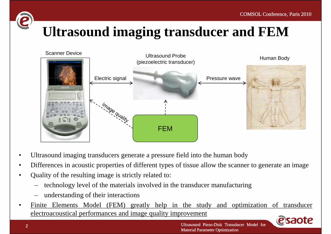
• Ultrasoundimagingtransducersgenerateapressurefield into thehumanbody
Pressure waveElectric signal
FEM
Ultrasound Piezo-Disk Transducer Model forMaterial Parameter Optimization
2 Ultrasound Piezo-Disk Transducer Model forMaterial Parameter Optimization
2
• Ultrasoundimagingtransducersgenerateapressurefield into thehumanbody
• Differences in acoustic properties of different types of tissue allow the scanner to generate an image
• Quality of the resulting image is strictly related to:
– technology level of the materials involved in the transducer manufacturing
– understanding of their interactions
• Finite Elements Model (FEM) greatly help in the study and optimization of transducerelectroacoustical performances and image quality improvement
COMSOL Conference, Paris 2010COMSOL Conference, Paris 2010
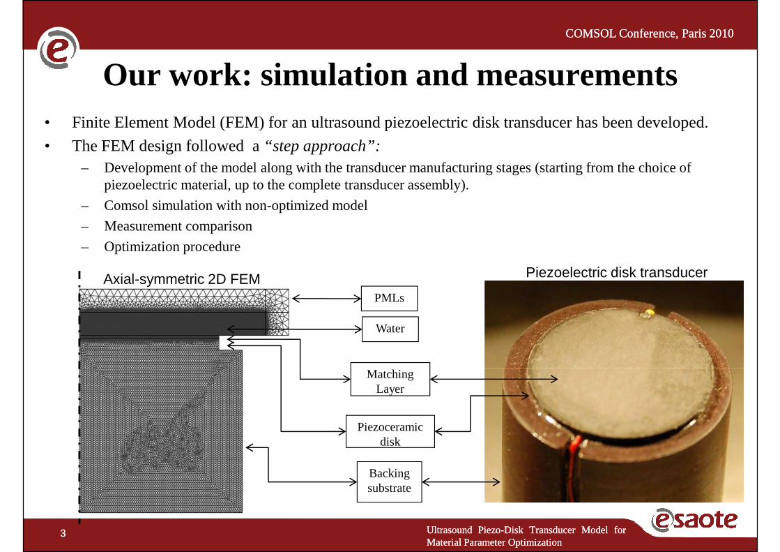
Our work: simulation and measurements• Finite Element Model (FEM) for an ultrasound piezoelectric disk transducer has been developed.
• The FEM design followed a “step approach”:– Development of the model along with the transducer manufacturing stages (starting from the choice of
piezoelectric material, up to the complete transducer assembly).
Matching
Water
Axial-symmetric 2D FEM Piezoelectric disk transducer
piezoelectric material, up to the complete transducer assembly).
– Comsol simulation with non-optimized model
– Measurement comparison
– Optimization procedure
PMLs
Ultrasound Piezo-Disk Transducer Model forMaterial Parameter Optimization
3 Ultrasound Piezo-Disk Transducer Model forMaterial Parameter Optimization
3
Backing substrate
Piezoceramic disk
Matching Layer

COMSOL Conference, Paris 2010COMSOL Conference, Paris 2010
Transducer Electro-acoustical measurements
• The most important measurements to determine the quality of the transducer and its consequent imaging performances are:
– Electrical impedance(performed with Network Analyzer):
• Determines resonance frequency of principal vibration modes
• Determines piezoelectric coupling efficiency
– Emitted pressure bandwidth(performed with Pulser-water tank-hydrophone-oscilloscope system):
• Determines transducer spatial resolution
Ultrasound Piezo-Disk Transducer Model forMaterial Parameter Optimization
4 Ultrasound Piezo-Disk Transducer Model forMaterial Parameter Optimization
4
Corresponding Simulation: a FEM frequency responseanalysis is to beperformed in order to compare simulation results with the measurementsabove
• Determines transducer sensitivity for different frequencies
COMSOL Conference, Paris 2010COMSOL Conference, Paris 2010
Main results
Measured and simulated transducer performances comparison• Electrical impedance • Electrical impedance
– error of less then 3% in resonant frequencies and amplitudes
• Far field pressure level measured in water – error of less then 1dB in maximum pressure amplitude
Optimization procedure• Takingadvantageof the simplicity of the problemunder study, it
Ultrasound Piezo-Disk Transducer Model forMaterial Parameter Optimization
5 Ultrasound Piezo-Disk Transducer Model forMaterial Parameter Optimization
5
• Takingadvantageof the simplicity of the problemunder study, itwas possible to establish an optimization procedure that could befollowed for future works
COMSOL Conference, Paris 2010COMSOL Conference, Paris 2010
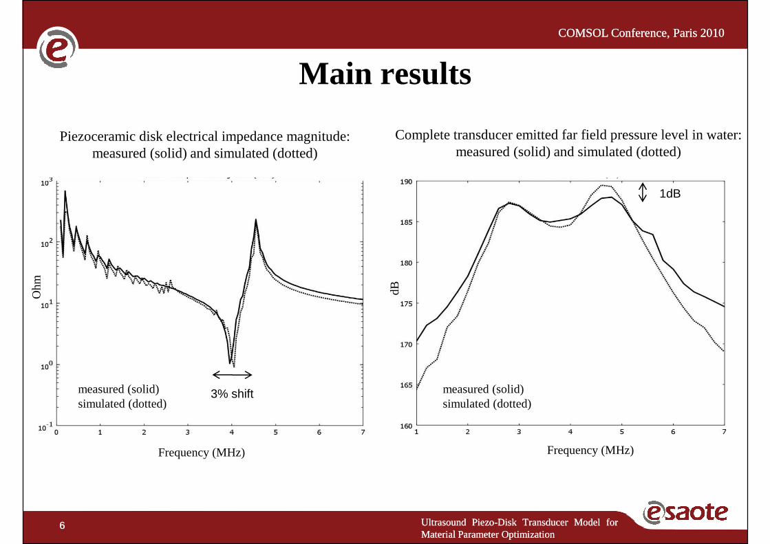
Piezoceramic disk electrical impedance magnitude: measured (solid) and simulated (dotted)
Complete transducer emitted far field pressure level in water: measured (solid) and simulated (dotted)
Main results
dBOhm
1dB
Ultrasound Piezo-Disk Transducer Model forMaterial Parameter Optimization
6 Ultrasound Piezo-Disk Transducer Model forMaterial Parameter Optimization
6
Frequency (MHz) Frequency (MHz)
measured (solid)simulated (dotted)
measured (solid)simulated (dotted)
3% shift

COMSOL Conference, Paris 2010COMSOL Conference, Paris 2010
Piezoelectricity equation in COMSOLThe constitutive equations for a piezoelectric material are (stress-chargeform):
(the superscripts indicates a zero or constant corresponding field)
[ ] -
t =
= +
E
S
T c S e E
D e S ε E
T: stress vector,c : elasticity matrix,S : strain vector,e : piezoelectric matrix,E : electric field vector,D : electric displacement vector,εεεε : dielectric permittivity matrix.
Ultrasound Piezo-Disk Transducer Model forMaterial Parameter Optimization
7 Ultrasound Piezo-Disk Transducer Model forMaterial Parameter Optimization
7
• Elasticity, piezoelectric and dielectric permittivity matrices must be specified to build the model in Comsol
• Unfortunately manufacturer data are often incomplete and should be checked for the particular operating condition of the piezoelectric material.
• Physical insight is the starting point for the model
• Optimization procedure should be used
COMSOL Conference, Paris 2010COMSOL Conference, Paris 2010
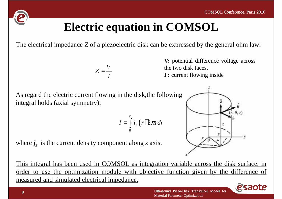
V
Electric equation in COMSOLThe electrical impedance Z of a piezoelectric disk can be expressed by the general ohm law:
V: potential difference voltage acrossthetwo disk faces,V
ZI
=
( )0
2r
zI j r rdrπ= ∫
thetwo disk faces,I : current flowing inside
As regard the electric current flowing in the disk,the following integral holds (axial symmetry):
Ultrasound Piezo-Disk Transducer Model forMaterial Parameter Optimization
8 Ultrasound Piezo-Disk Transducer Model forMaterial Parameter Optimization
8
wherejz is the current density component alongzaxis.
This integral has been used in COMSOL as integration variable across the disk surface, inorder to use the optimization module with objective function given by the difference ofmeasured and simulated electrical impedance.
COMSOL Conference, Paris 2010COMSOL Conference, Paris 2010
( ) ( )22 ,1
, 0p r t
p r t∂
∇ − =p is the pressure,c is thespeedof soundin the
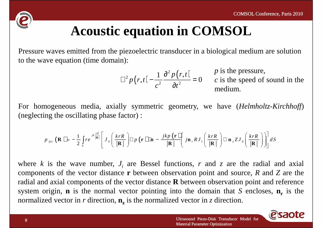
Acoustic equation in COMSOLPressure waves emitted from the piezoelectric transducer in a biological medium are solution to the wave equation (time domain):
( ) ( )22 2
,1, 0
p r tp r t
c t
∂∇ − =
∂c is thespeedof soundin themedium.
For homogeneous media, axially symmetric geometry, we have (Helmholtz-Kirchhoff)(neglecting the oscillating phase factor) :
( ) ( ) ( )0 1 0
1
2
zZj k
fa r r z
S
jkpkrR krR krRp re J p j R J Z J d S
− ∇ ⋅ − +
∫R r
R r n n nR R R R
≃
Ultrasound Piezo-Disk Transducer Model forMaterial Parameter Optimization
9 Ultrasound Piezo-Disk Transducer Model forMaterial Parameter Optimization
9
where k is the wave number,Ji are Bessel functions,r and z are the radial and axialcomponents of the vector distancer between observation point and source,R andZ are theradial and axial components of the vector distanceR between observation point and referencesystem origin,n is the normal vector pointing into the domain thatS encloses,nr is thenormalized vector inr direction,nz is the normalized vector inz direction.
COMSOL Conference, Paris 2010COMSOL Conference, Paris 2010
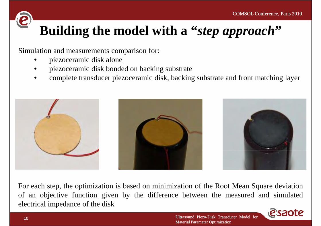
Building the model with a “step approach”Simulation and measurements comparison for:
• piezoceramic disk alone• piezoceramic disk bonded on backing substrate• completetransducerpiezoceramicdisk,backingsubstrateandfront matchinglayer• completetransducerpiezoceramicdisk,backingsubstrateandfront matchinglayer
Ultrasound Piezo-Disk Transducer Model forMaterial Parameter Optimization
10 Ultrasound Piezo-Disk Transducer Model forMaterial Parameter Optimization
10
For each step, the optimization is based on minimization of the Root Mean Square deviationof an objective function given by the difference between the measured and simulatedelectrical impedance of the disk
COMSOL Conference, Paris 2010COMSOL Conference, Paris 2010
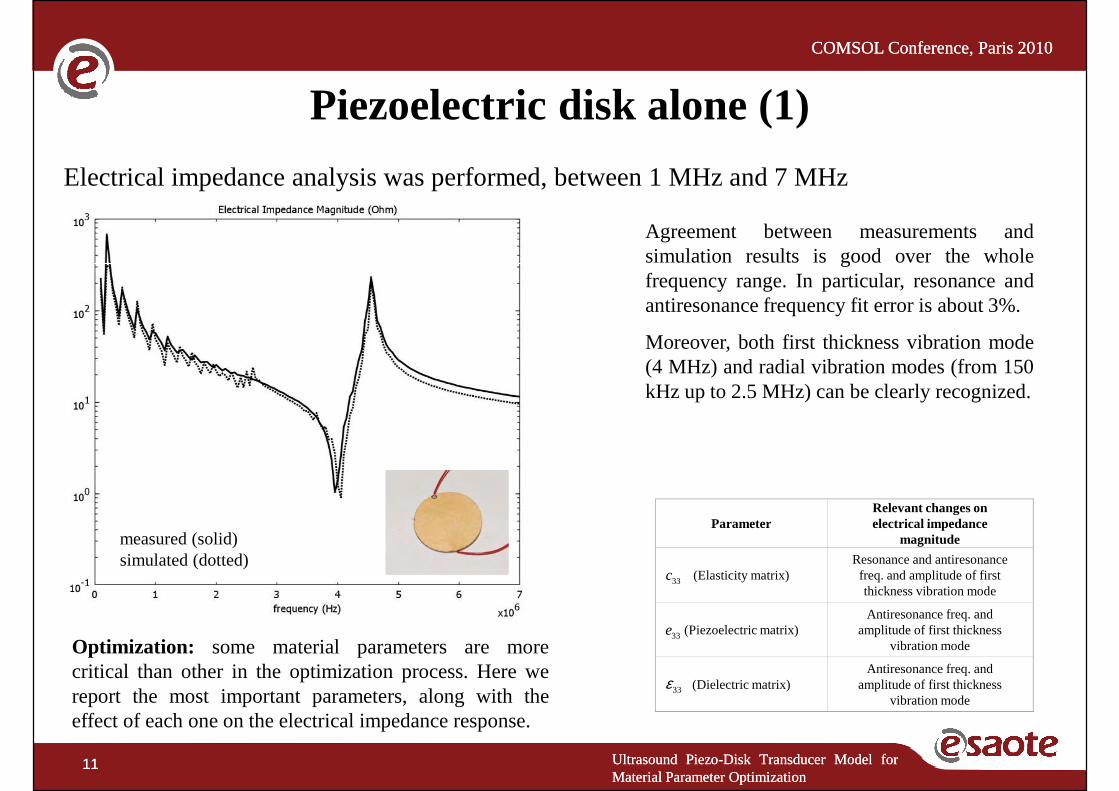
Agreement between measurements andsimulation results is good over the whole
Piezoelectric disk alone (1)
Electrical impedance analysis was performed, between 1 MHz and 7 MHz
simulation results is good over the wholefrequency range. In particular, resonance andantiresonance frequency fit error is about 3%.
Moreover, both first thickness vibration mode(4 MHz) and radial vibration modes (from 150kHz up to 2.5 MHz) can be clearly recognized.
ParameterRelevant changes on electrical impedance
Ultrasound Piezo-Disk Transducer Model forMaterial Parameter Optimization
11 Ultrasound Piezo-Disk Transducer Model forMaterial Parameter Optimization
11
Optimization: some material parameters are morecritical than other in the optimization process. Here wereport the most important parameters, along with theeffect of each one on the electrical impedance response.
33c
33e
33ε
Parameter electrical impedance magnitude
(Elasticity matrix)Resonance and antiresonance freq. and amplitude of first thickness vibration mode
(Piezoelectric matrix)Antiresonance freq. and
amplitude of first thickness vibration mode
(Dielectric matrix)Antiresonance freq. and
amplitude of first thickness vibration mode
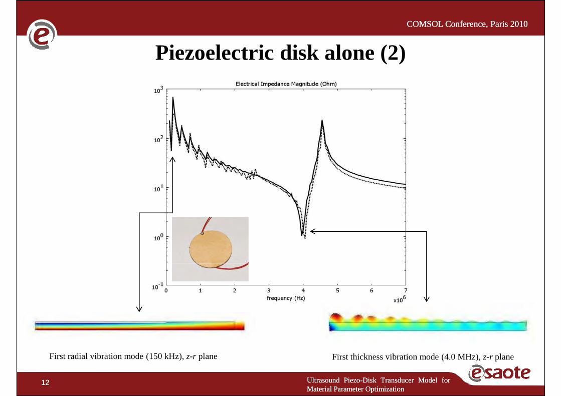
measured (solid)simulated (dotted)
COMSOL Conference, Paris 2010COMSOL Conference, Paris 2010
Piezoelectric disk alone (2)
Ultrasound Piezo-Disk Transducer Model forMaterial Parameter Optimization
12 Ultrasound Piezo-Disk Transducer Model forMaterial Parameter Optimization
12
First thickness vibration mode (4.0 MHz),z-r planeFirst radial vibration mode (150 kHz),z-r plane
COMSOL Conference, Paris 2010COMSOL Conference, Paris 2010
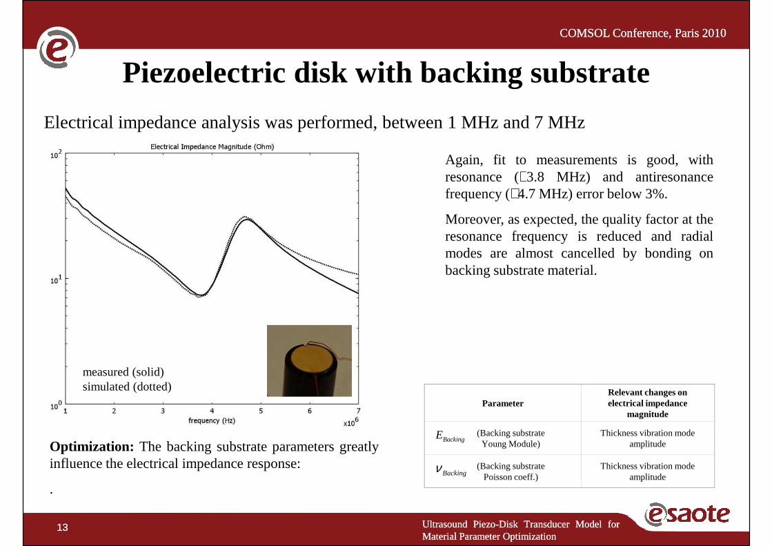
Again, fit to measurements is good, withresonance (∼3.8 MHz) and antiresonance
Piezoelectric disk with backing substrate
Electrical impedance analysis was performed, between 1 MHz and 7 MHz
resonance (∼3.8 MHz) and antiresonancefrequency (∼4.7 MHz) error below 3%.
Moreover, as expected, the quality factor at theresonance frequency is reduced and radialmodes are almost cancelled by bonding onbacking substrate material.
Ultrasound Piezo-Disk Transducer Model forMaterial Parameter Optimization
13 Ultrasound Piezo-Disk Transducer Model forMaterial Parameter Optimization
13
Optimization: The backing substrate parameters greatlyinfluence the electrical impedance response:
.
measured (solid)simulated (dotted)
BackingE
Backingν
ParameterRelevant changes on electrical impedance
magnitude
(Backing substrate Young Module)
Thickness vibration mode amplitude
(Backing substratePoisson coeff.)
Thickness vibration mode amplitude
COMSOL Conference, Paris 2010COMSOL Conference, Paris 2010
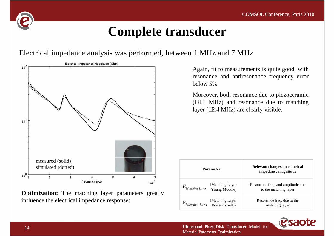
Again, fit to measurements is quite good, withresonanceand antiresonancefrequencyerror
Complete transducer
Electrical impedance analysis was performed, between 1 MHz and 7 MHz
resonanceand antiresonancefrequencyerrorbelow 5%.
Moreover, both resonance due to piezoceramic(∼4.1 MHz) and resonance due to matchinglayer (∼2.4 MHz) are clearly visible.
Ultrasound Piezo-Disk Transducer Model forMaterial Parameter Optimization
14 Ultrasound Piezo-Disk Transducer Model forMaterial Parameter Optimization
14
Optimization: The matching layer parameters greatlyinfluence the electrical impedance response:
measured (solid) simulated (dotted)measured (solid)simulated (dotted)
Matching LayerE
Matching Layerν
ParameterRelevant changes on electrical
impedance magnitude
(Matching Layer Young Module)
Resonance freq. and amplitude due to the matching layer
(Matching Layer Poisson coeff.)
Resonance freq. due to the matching layer
COMSOL Conference, Paris 2010COMSOL Conference, Paris 2010
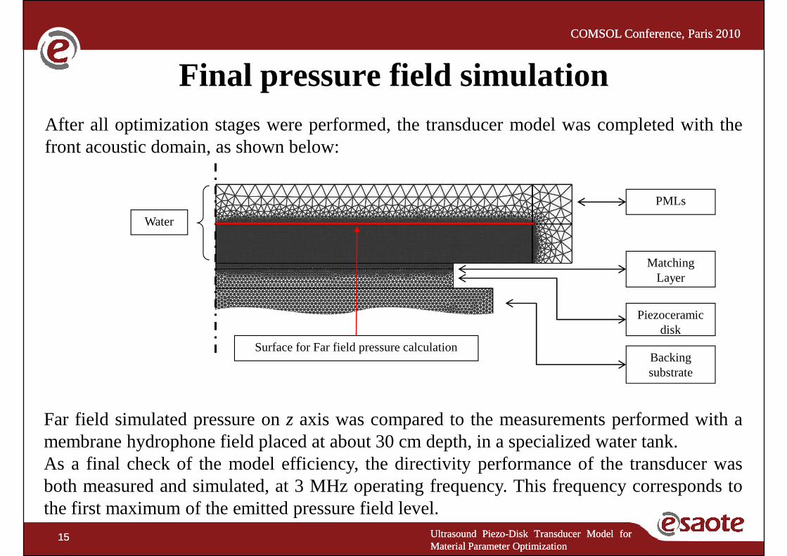
Final pressure field simulationAfter all optimization stages were performed, the transducer model was completed with thefront acoustic domain, as shown below:
Backing substrate
Piezoceramic disk
Matching Layer
Water
PMLs
Surface for Far field pressure calculation
Ultrasound Piezo-Disk Transducer Model forMaterial Parameter Optimization
15 Ultrasound Piezo-Disk Transducer Model forMaterial Parameter Optimization
15
substrate
Far field simulated pressure onz axis was compared to the measurements performed with amembrane hydrophone field placed at about 30 cm depth, in a specialized water tank.As a final check of the model efficiency, the directivity performance of the transducer wasboth measured and simulated, at 3 MHz operating frequency. This frequency corresponds tothe first maximum of the emitted pressure field level.
COMSOL Conference, Paris 2010COMSOL Conference, Paris 2010
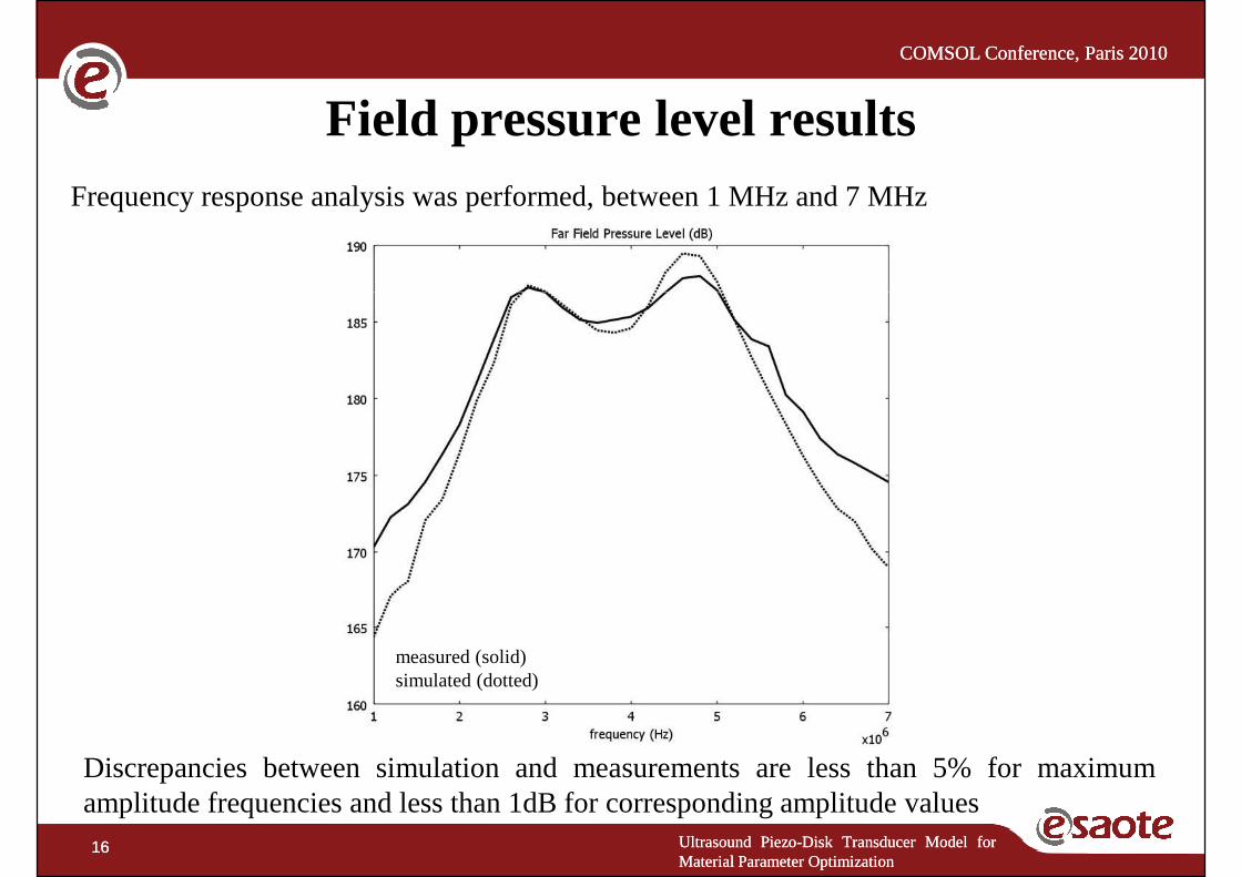
Field pressure level resultsFrequency response analysis was performed, between 1 MHz and 7 MHz
Ultrasound Piezo-Disk Transducer Model forMaterial Parameter Optimization
16 Ultrasound Piezo-Disk Transducer Model forMaterial Parameter Optimization
16
Discrepancies between simulation and measurements are less than 5% for maximumamplitude frequencies and less than 1dB for corresponding amplitude values
measured (solid)simulated (dotted)
COMSOL Conference, Paris 2010COMSOL Conference, Paris 2010
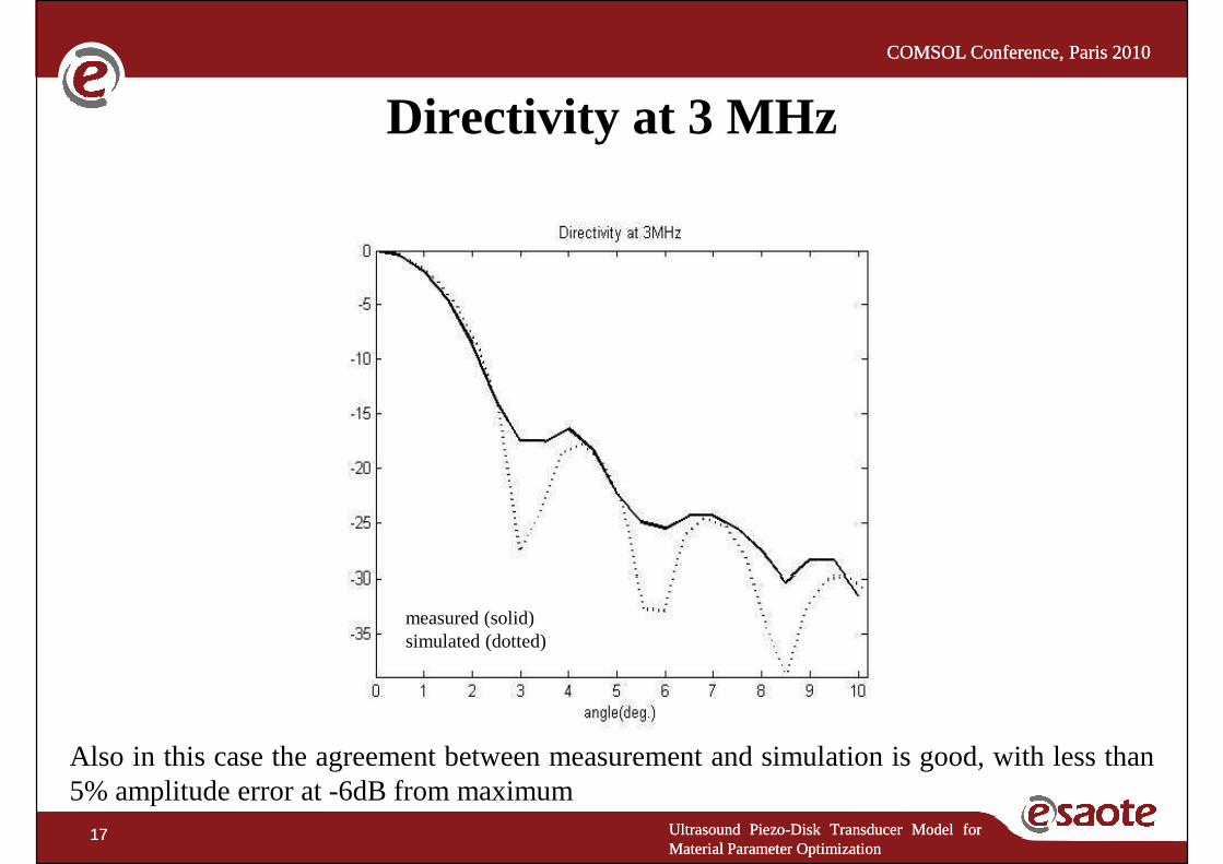
Directivity at 3 MHz
Ultrasound Piezo-Disk Transducer Model forMaterial Parameter Optimization
17 Ultrasound Piezo-Disk Transducer Model forMaterial Parameter Optimization
17
Also in this case the agreement between measurement and simulation is good, with less than5% amplitude error at -6dB from maximum
measured (solid)simulated (dotted)
COMSOL Conference, Paris 2010COMSOL Conference, Paris 2010
A Finite Element Model (FEM) for an ultrasound piezoelectrictransducer has been developed.
Conclusion
The FEM design follows a“step approach” which consists inthe development of the model along with the transducermanufacturing stages.
Final results for the far field pressure level show a goodagreement between measured and simulated transducerperformances,even better results are obtained in terms of
Ultrasound Piezo-Disk Transducer Model forMaterial Parameter Optimization
18 Ultrasound Piezo-Disk Transducer Model forMaterial Parameter Optimization
18
performances,even better results are obtained in terms ofelectric impedance.
COMSOL Conference, Paris 2010COMSOL Conference, Paris 2010
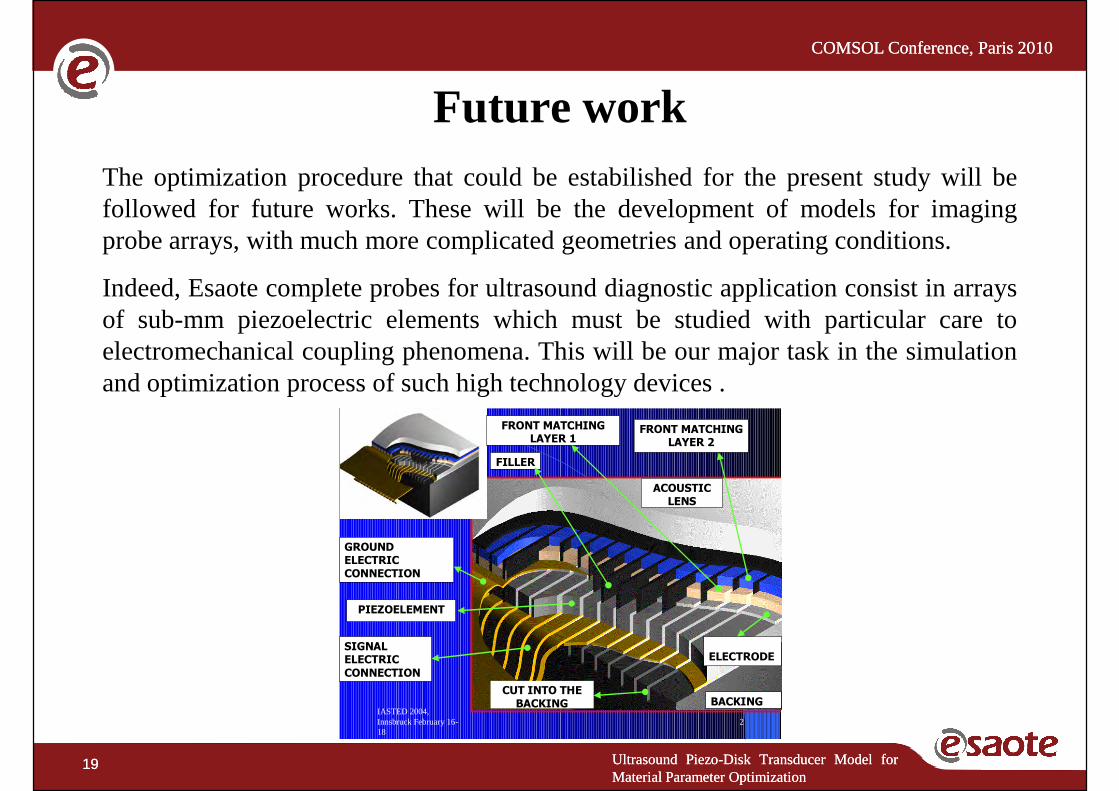
The optimization procedure that could be estabilished for the present study will befollowed for future works. These will be the development of models for imagingprobe arrays, with much more complicated geometries and operating conditions.
Future work
Indeed, Esaote complete probes for ultrasound diagnostic application consist in arraysof sub-mm piezoelectric elements which must be studied with particular care toelectromechanical coupling phenomena. This will be our major task in the simulationand optimization process of such high technology devices .
FRONT MATCHING
LAYER 1
ACOUSTIC
LENS
FRONT MATCHING
LAYER 2
FILLER
Ultrasound Piezo-Disk Transducer Model forMaterial Parameter Optimization
19 Ultrasound Piezo-Disk Transducer Model forMaterial Parameter Optimization
19
IASTED 2004, Innsbruck February 16-18
2
BACKING
PIEZOELEMENT
UPPER
ELECTRODE
CUT INTO THE
BACKING
SIGNAL
ELECTRIC
CONNECTION
GROUND
ELECTRIC
CONNECTION
COMSOL Conference, Paris 2010COMSOL Conference, Paris 2010
Ultrasound Piezo-Disk Transducer Model for Ultrasound Piezo-Disk Transducer Model for Material Parameter Optimization
Lorenzo Spicci, Marco Cati
Ultrasound Piezo-Disk Transducer Model forMaterial Parameter Optimization
20 Ultrasound Piezo-Disk Transducer Model forMaterial Parameter Optimization
20
Research and Development Department, Esaote S.p.A.,Via di Caciolle 15, 50127, Florence, Italy.