Ultrasonic welding of CF/PPS composites with integrated...
16
Delft University of Technology Ultrasonic welding of CF/PPS composites with integrated triangular energy directors melting, flow and weld strength development Fernandez Villegas, Irene; Palardy, Genevieve DOI 10.1080/09276440.2017.1236626 Publication date 2017 Document Version Final published version Published in Composite Interfaces (Print) Citation (APA) Villegas, I. F., & Palardy, G. (2017). Ultrasonic welding of CF/PPS composites with integrated triangular energy directors: melting, flow and weld strength development. Composite Interfaces (Print), 24(5), 515- 528. https://doi.org/10.1080/09276440.2017.1236626 Important note To cite this publication, please use the final published version (if applicable). Please check the document version above. Copyright Other than for strictly personal use, it is not permitted to download, forward or distribute the text or part of it, without the consent of the author(s) and/or copyright holder(s), unless the work is under an open content license such as Creative Commons. Takedown policy Please contact us and provide details if you believe this document breaches copyrights. We will remove access to the work immediately and investigate your claim. This work is downloaded from Delft University of Technology. For technical reasons the number of authors shown on this cover page is limited to a maximum of 10.
Transcript of Ultrasonic welding of CF/PPS composites with integrated...

Delft University of Technology
Ultrasonic welding of CF/PPS composites with integrated triangular energy directorsmelting, flow and weld strength developmentFernandez Villegas, Irene; Palardy, Genevieve
DOI10.1080/09276440.2017.1236626Publication date2017Document VersionFinal published versionPublished inComposite Interfaces (Print)
Citation (APA)Villegas, I. F., & Palardy, G. (2017). Ultrasonic welding of CF/PPS composites with integrated triangularenergy directors: melting, flow and weld strength development. Composite Interfaces (Print), 24(5), 515-528. https://doi.org/10.1080/09276440.2017.1236626
Important noteTo cite this publication, please use the final published version (if applicable).Please check the document version above.
CopyrightOther than for strictly personal use, it is not permitted to download, forward or distribute the text or part of it, without the consentof the author(s) and/or copyright holder(s), unless the work is under an open content license such as Creative Commons.
Takedown policyPlease contact us and provide details if you believe this document breaches copyrights.We will remove access to the work immediately and investigate your claim.
This work is downloaded from Delft University of Technology.For technical reasons the number of authors shown on this cover page is limited to a maximum of 10.

Full Terms & Conditions of access and use can be found athttp://www.tandfonline.com/action/journalInformation?journalCode=tcoi20
Download by: [Bibliotheek TU Delft] Date: 27 February 2017, At: 07:37
Composite Interfaces
ISSN: 0927-6440 (Print) 1568-5543 (Online) Journal homepage: http://www.tandfonline.com/loi/tcoi20
Ultrasonic welding of CF/PPS composites withintegrated triangular energy directors: melting,flow and weld strength development
Irene Fernandez Villegas & Genevieve Palardy
To cite this article: Irene Fernandez Villegas & Genevieve Palardy (2017) Ultrasonic welding ofCF/PPS composites with integrated triangular energy directors: melting, flow and weld strengthdevelopment, Composite Interfaces, 24:5, 515-528, DOI: 10.1080/09276440.2017.1236626
To link to this article: http://dx.doi.org/10.1080/09276440.2017.1236626
© 2016 The Author(s). Published by InformaUK Limited, trading as Taylor & FrancisGroup
Published online: 03 Oct 2016.
Submit your article to this journal Article views: 64
View related articles View Crossmark data
Citing articles: 1 View citing articles
Composite interfaCes, 2017VoL. 24, no. 5, 515–528http://dx.doi.org/10.1080/09276440.2017.1236626
Ultrasonic welding of CF/PPS composites with integrated triangular energy directors: melting, flow and weld strength development
Irene Fernandez Villegas and Genevieve Palardy
structural integrity and Composites Group, faculty of aerospace engineering, Delft University of technology, Delft, the netherlands
ABSTRACTThis paper presents a fully experimental study on melting, flow and weld strength development during ultrasonic welding of CF/PPS composites with integrated triangular energy directors. The main goal of this research was assessing whether the heating time to achieve maximum weld strength could be significantly reduced as compared to ultrasonic welding with flat energy directors. The main conclusion is that, in the specific case under study, the triangular energy directors did heat up, melt and collapse approximately two times faster than the time it took for the flat energy directors to melt and significantly flow. However the heating time needed to achieve maximum weld strength for the integrated triangular energy directors did not differ drastically from that for flat energy directors. This was caused by the fact that a fully welded overlap was not directly achieved right after the collapsing of the triangular energy directors. Instead a solidified resin-rich interface was created which needed to be re-melted as a whole in order to achieve a fully welded overlap and hence maximum weld strength.
Introduction
Ultrasonic welding is a joining technique widely used in the plastics industry and also considered as a promising solution for the assembly of thermoplastic composite structures. Ultrasonic heat generation in plastics and polymeric composites is concentrated at the welding interface through the so-called energy directors (EDs), which usually are resin protrusions on the surfaces to be welded.[1] Heat concentration at the welding interface is based firstly on the relative movement between EDs and substrates, which generates surface friction heating,[2] and secondly on a relatively bigger cyclic strain in the EDs, which gen-erates viscoelastic friction heating.[1,2] Non-reinforced plastic parts are directly manufac-tured with integrated EDs, generally with a triangular cross section,[1] on the surfaces to be welded. The higher cyclic strain in the EDs originates in their smaller cross section relative to the adherends. These traditional EDs have as well been used in research on ultrasonic welding of thermoplastic composites. They however pose some manufacturing challenges
KEYWORDSthermoplastic composites; ultrasonic welding; triangular energy directors; flat energy directors
ARTICLE HISTORYreceived 11 July 2016 accepted 12 september 2016
© 2016 the author(s). published by informa UK Limited, trading as taylor & francis Group.this is an open access article distributed under the terms of the Creative Commons attribution-nonCommercial-noDerivatives License (http://creativecommons.org/licenses/by-nc-nd/4.0/), which permits non-commercial re-use, distribution, and reproduction in any medium, provided the original work is properly cited, and is not altered, transformed, or built upon in any way.
CONTACT irene fernandez Villegas [email protected]
OPEN ACCESS

516 I. F. VIlleGaS and G. Palardy
such as increasing of manufacturing steps due to the necessity of moulding the EDs on the composite laminates or fibre disruption in composite adherends.[3] Tateishi et al. explored the alternative possibility of using tie-layers as EDs for ultrasonically welding of oriented polypropylene.[4] The same ED type, referred to as ‘flat ED’, was later on proven as a simple alternative for the welding of advanced thermoplastic composites able to provide strong and consistent welds.[5,6] In that case, the higher cyclic strain in the ED is not geometry-based as in the case of triangular EDs but results from different material properties at the welding interface.[7] Owing to the bigger contact surface between the flat ED and adherends, surface friction is also believed to play a more important role than in triangular EDs.
In previous work,[6] we comparatively evaluated flat and triangular EDs for ultrasonic welding of continuous carbon fibre reinforced polyphenylene sulphide (CF/PPS) compos-ites. The goal was to assess any potential shortcomings associated to the usage of flat EDs as compared to traditional ED solutions. In general no big differences regarding weld strength, dissipated power or heating time could be found. However, difficulties encountered on moulding the triangular EDs on the surface of composite laminates limited the study to EDs consisting of triangular ridges moulded on a loose resin layer as the more traditional alternative to flat EDs. One of our observations was that, as expected, the triangular ridges started melting and flowing much faster that the flat ED. This is consistent with the results of Yan et al. [8] according to which the time to reach Tg in a triangular ED is much lower than in a rectangular ED (which bears some similarity with flat EDs). However, this faster process did eventually come to a halt, which was attributed to the much slower melting and flow of the resin layer that supported the triangular ridges. Consequently, the heating time for maximum weld strength did not differ much from that of the flat ED. Nevertheless these results seemed to indicate a potential for significant heating time reductions when triangular EDs are directly moulded onto the composite substrates. Even though ultrasonic welding is known to be a very fast process, the possibility of reducing heating times even further could be very favourable for specific applications. One of them is high-temperature welding of thermoplastic to epoxy-based composites, when the latter are made ‘weldable’ through a layer of thermoplastic coating.[9] As proven in [10], thermal degradation of the thermoset composite during the welding process can be readily prevented by drastically decreasing the heating time, typically below 500 ms. These very short heating times can be effectively achieved with flat EDs but at the cost of an increase in the dissipated power since both high welding pressure and high amplitude are required to reduce the heating time. Alternative ED solutions could help widen the processing window while relaxing the power requirements for this type of processes.
In order to assess whether integrated triangular EDs can offer significant reductions in the time needed to reach maximum weld strength, knowledge on the heating, flow and weld strength development at the welding interface is deemed necessary. Regarding the heating process, researchers agree on the fact that heating up to Tg or Tm and, hence softening or melting of the thermoplastic resin, first occurs in the vicinity of the tip of the triangular EDs.[8,11,12] There is also agreement in the literature on the fact that, once the viscosity of the resin in the vicinity of the tip of the triangular EDs is below a certain value, it will be squeezed out and the distance between the adherends will start to decrease until the resin completely fills out the gap at the interface.[11,12] In their work on ultrasonic welding of continuous carbon fibre reinforced polyether ether ketone (CF/PEEK) composites, Benatar and Gutowski [11] describe melting of the triangular EDs as a step-like process in which

ComPoSITe InTerFaCeS 517
the melt fronts freeze and are subsequently re-melted. Freezing of the melt fronts occurs as they get in contact with the (colder) adherends [8,11] and heat is transferred away by the carbon fibres (with a thermal conductivity approximately 100 times higher than that of the matrix [13]). Alternatively, Levy et al. [12] describe melting of the triangular EDs during ultrasonic welding of CF/PEEK composites through the formation of a fold that flows to fill the gap in between the adherends. Regarding the development of weld strength there is also lack of general agreement in the open literature. Benatar and Gutowski [11] state that maximum weld strength is achieved when the melt fronts from all the energy directors meet, which coincides with a sudden increase in the mechanical impedance of the molten interface. However, the theoretical predictions of Levy et al. [12] indicate that the interface is not completely healed at that time in the process and the authors suggest that, based on the trends they observe, total healing is probably achieved during the cooling phase of the welding process. Alternatively, Ling et al. [14] state that once the ‘melting layer’ has closed the gaps at the welding interface some time at high temperature is needed to melt the contact faces of the adherends before molecular interdiffusion and hence healing can occur.
This paper focuses on increasing the current knowledge on melting, flow and weld strength development during ultrasonic welding of thermoplastic composites with inte-grated triangular EDs with the main goal of assessing whether this ED type can offer signif-icant reductions in the heating time as compared to flat EDs. A fully experimental approach is followed according to which melting and flow of the EDs are monitored through the feedback provided by the ultrasonic welder on dissipated power and vertical displacement of the sonotrode, as well as cross-section microscopy and fractographic analysis. The devel-opment of weld strength is assessed through mechanical testing.
Experimental
The thermoplastic composite material used in this research was carbon fibre fabric (five harness satin) reinforced polyphenylene sulphide (CF/PPS) from Ten Cate Advanced Composites (The Netherlands). A T300JB carbon fibre was used in this composite with a nominal 50% fibre volume content. Two types of composite laminates were manufactured, namely CF/PPS laminates with integrated triangular EDs and plain CF/PPS laminates. In both cases, six powder-impregnated prepreg layers were stacked in a ([0/90]3)S configuration and a hot platen press was used to consolidate the composite material at 320 °C and 1 MPa for 15 min. In the case of the CF/PPS laminates with integrated triangular EDs a mould was also used which consisted of two parallel thick aluminium plates, one of them with triangular grooves machined on its surface (see Figure 1(a)). Following the procedure used by Benatar and Gutowski [11] and Harras et al. [15], five layers of neat 0.08-mm thick PPS resin were added to the side of the prepreg stack facing the triangular grooves for a one-step manufacturing of the CF/PPS laminates with integrated EDs (Figure 1(a)). As shown in Figure 1(b), this procedure provided good quality laminates and EDs. The final height of the EDs as measured on the cross-section micrograph was 0.5 mm. They showed a somewhat rounded tip most probably due to the high viscosity of PPS preventing complete filling of the mould. It must be noted that the prepreg stack was positioned so that the main apparent orientation of the fibres on its outer sides was perpendicular to the triangular grooves. After manufacturing, 101.6-mm long and 25.4-mm wide adherends were water-jet cut from the

518 I. F. VIlleGaS and G. Palardy
two laminate types with their longest side parallel to the main apparent fibre orientation. In the case of the laminates with integrated EDs, the adherends were cut so that the EDs were centred in the welding overlap. The adherends were degreased prior to welding.
Individual samples were welded in a single lap configuration with a 12.7 mm long over-lap. For this purpose a microprocessor-controlled Dynamic 3000 Rinco ultrasonic welder equipped with a 40-mm diameter cylindrical sonotrode and a custom-built welding jig which allows vertical displacement of the top adherend during the welding process (see Figure 2(a)) were used. The welding configuration used in this study, as shown in Figure 2(b), consisted of a bottom adherend with integrated EDs and a top plain adherend. In order to allow direct comparison with our previous work on flat energy directors for welding of CF/PPS composites [6] the same welding parameters were used in this study, i.e., 500 N welding force, 86.2 μm peak-to-peak welding amplitude, 1000 N solidification force and 4 s
Figure 1. (a) schematic of mould and stack prior to manufacturing of laminates with triangular eDs (dimensions in mm, sketch not to scale). (b) Cross-section micrograph showing triangular eDs moulded on Cf/pps laminate. approximate final height of triangles is 0.5 mm.
Figure 2. (a) Ultrasonic welder and welding jig used in this research, where (1) sonotrode, (2) sliding support for top clamp, (3) top clamp, (4) bottom clamp. (b) schematic of sample positioning prior to welding process.
ComPoSITe InTerFaCeS 519
solidification time. The reader must note that both the welding force and the amplitude have a significant effect in the heating times during the welding process as explained in [16] and hence they have to remain unchanged to make the comparative study valid. Displacement-controlled welding was used as the reference welding procedure. Energy-controlled welding was used in those cases where displacement control was not possible.
As already mentioned, the melting and flow behaviour of the integrated EDs during the welding process was mainly evaluated through analysis of the feedback data provided by the ultrasonic welder on power consumed and vertical displacement of the sonotrode. Cross-section optical microscopy of welded samples as well as fractography were also used with this purpose. The development of joint strength during the welding process was assessed through static single-lap shear testing following ASTM D 1002 standard in a 250kN Zwick Universal Test Bench.
Results and discussion
Melting and flow behaviour
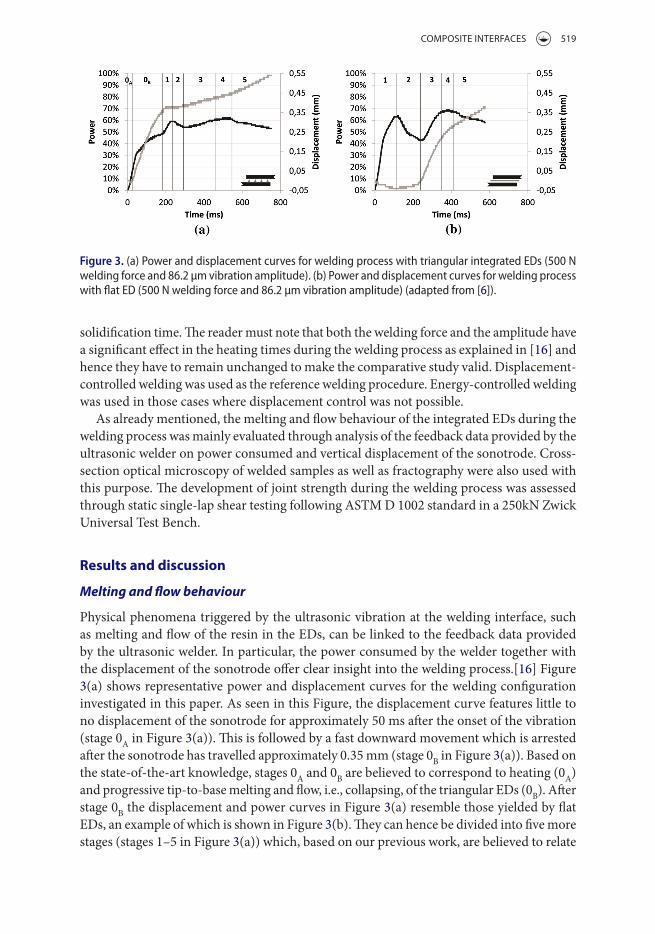
Physical phenomena triggered by the ultrasonic vibration at the welding interface, such as melting and flow of the resin in the EDs, can be linked to the feedback data provided by the ultrasonic welder. In particular, the power consumed by the welder together with the displacement of the sonotrode offer clear insight into the welding process.[16] Figure 3(a) shows representative power and displacement curves for the welding configuration investigated in this paper. As seen in this Figure, the displacement curve features little to no displacement of the sonotrode for approximately 50 ms after the onset of the vibration (stage 0A in Figure 3(a)). This is followed by a fast downward movement which is arrested after the sonotrode has travelled approximately 0.35 mm (stage 0B in Figure 3(a)). Based on the state-of-the-art knowledge, stages 0A and 0B are believed to correspond to heating (0A) and progressive tip-to-base melting and flow, i.e., collapsing, of the triangular EDs (0B). After stage 0B the displacement and power curves in Figure 3(a) resemble those yielded by flat EDs, an example of which is shown in Figure 3(b). They can hence be divided into five more stages (stages 1–5 in Figure 3(a)) which, based on our previous work, are believed to relate
Figure 3. (a) power and displacement curves for welding process with triangular integrated eDs (500 n welding force and 86.2 μm vibration amplitude). (b) power and displacement curves for welding process with flat eD (500 n welding force and 86.2 μm vibration amplitude) (adapted from [6]).

520 I. F. VIlleGaS and G. Palardy
to physical changes at the welding interface [16] after the collapsing of the triangular EDs. It must be noted that, similarly to what we previously observed in the case of EDs consisting of a loose resin film with moulded triangular EDs,[6] the displacement of the sonotrode was temporarily halted right after stage 0B when the triangular EDs were integrated in the composite adherend. As described in the Introduction, in the case of the resin film with moulded triangular EDs this phenomenon was attributed to the slower heating and melting of the resin film. In the present study, however, that was clearly not the case, since the tri-angular EDs were directly moulded on the adherends. In order to better understand these results and to assess their influence on the heating time needed to attain maximum weld strength further experiments were performed. These entailed cross-sectional micrographic observations of samples welded in some of the stages identified in Figure 3(a), namely 0B, 1, 3 and 4, as well as occasional fractographic analysis after mechanical testing of some of those samples. The results are presented and discussed in what follows.
Figure 4(a) shows a cross-section micrograph of a single-lap sample subjected to ultra-sonic vibration up until stage 0B (Figure 4(b)) followed by solidification under pressure (1000 N for 4 s). This micrograph illustrates how melting of the triangular EDs starts at their tips and how the molten resin is squeezed out to their sides, which progressively rounds up the shape of the EDs. The reader should note that, since this sample was subjected to solidification after the vibration was stopped, the squeeze out observed on Figure 4(a) could be expected to be somehow bigger that what would actually correspond to stage 0B. It nev-ertheless serves the purpose of illustrating melting and flow of the EDs at that stage, which applies to all the cross-section micrographs (and fracture surfaces) shown in this section.
Figure 5(a) shows the cross-section micrograph of a sample subjected to ultrasonic vibration slightly beyond the beginning of stage 1 (Figure 5(b)) followed by solidification under pressure. According to this micrograph, stage 1 and hence the temporary halt of the sonotrode displacement seem to begin when the resin squeezed out from the EDs fills the gap between the adherends. This phenomenon is accompanied by a steeper increase in the dissipated power (see Figure 5(b)), which is in line with the increase in mechanical impedance observed by Benatar and Gutowski at the moment when the flow fronts from all the EDs meet.[11]
Figure 4. (a) Cross-section micrograph of sample welded within stage 0B (500 n welding force, 86.2 μm vibration amplitude and 0.19 mm displacement). (b) Corresponding power and displacement curves.

ComPoSITe InTerFaCeS 521
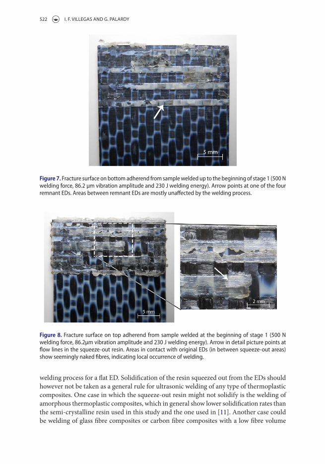
The sudden halt in the displacement of the sonotrode can be attributed to the existence of a physical barrier at the welding interface in the form of solidified PPS resin. Two are the main factors that contribute to the formation of such barrier. Firstly, remnant EDs in a solid state that did not get to melt before the squeeze-out resin filled the gap between the adherends. These solid remnant EDs can be observed in Figures 5(a) and 6 owing to the fact that they keep their original white appearance, characteristic of semi-crystalline PPS resin as obtained from the consolidation cycle in the hot platen press. The surrounding squeeze-out resin has however a darker appearance, due to its presumably amorphous or closer-to-amorphous state after the fast cooling in the solidification phase of the welding cycle. The fracture surface in Figure 7 clearly shows the remnant EDs, which after failure of the welded joint remain on the bottom adherend. Secondly, the squeeze-out resin also contributed to the physical barrier since it did solidify as it flowed away from the EDs and came into contact with the adjacent colder adherends.[8,11] The fracture surface and detail in Figure 8 support this hypothesis since the resin squeezed out from the EDs shows mul-tiple flow lines which indicate a step-like process in which portions of the EDs successively melt, are squeezed out and solidify, as also described by Benatar and Gutowski in [11]. Consequently, collapsing of the triangular EDs during stage 0B seems to result in a solidi-fied, resin-rich interface very much similar to the welding interface at the beginning of the
Figure 5. (a) Cross-section micrograph of sample welded up to the beginning of stage 1 (500 n welding force, 86.2 μm welding amplitude and 230 J welding energy). arrow indicates the position of remnant eD. (b) Corresponding power and displacement curves.
Figure 6. stereo-micrograph showing remnant eDs (indicated with arrows) in sample welded up to the beginning of stage 1 (500 n welding force, 86.2 μm welding amplitude and 230 J welding energy).
522 I. F. VIlleGaS and G. Palardy
welding process for a flat ED. Solidification of the resin squeezed out from the EDs should however not be taken as a general rule for ultrasonic welding of any type of thermoplastic composites. One case in which the squeeze-out resin might not solidify is the welding of amorphous thermoplastic composites, which in general show lower solidification rates than the semi-crystalline resin used in this study and the one used in [11]. Another case could be welding of glass fibre composites or carbon fibre composites with a low fibre volume
Figure 7. fracture surface on bottom adherend from sample welded up to the beginning of stage 1 (500 n welding force, 86.2 μm vibration amplitude and 230 J welding energy). arrow points at one of the four remnant eDs. areas between remnant eDs are mostly unaffected by the welding process.
Figure 8. fracture surface on top adherend from sample welded at the beginning of stage 1 (500 n welding force, 86.2μm vibration amplitude and 230 J welding energy). arrow in detail picture points at flow lines in the squeeze-out resin. areas in contact with original eDs (in between squeeze-out areas) show seemingly naked fibres, indicating local occurrence of welding.

ComPoSITe InTerFaCeS 523
fraction and hence with a reduced thermal conductivity as compared to the composite used here. In those cases the resin-rich welding interface would be composed of solidified (remnant un-molten EDs) and non-solidified (squeeze-out) resin. Owing to the physical barrier imposed by the remnant un-molten EDs to the vertical travel of the sonotrode, the displacement halt discussed earlier could however still be expected.
Figure 9(a) displays the cross-section micrograph of a sample welded within stage 3 (Figure 9(b)) and subjected to consolidation afterwards. This micrograph indicates that the resumed displacement of the sonotrode in stage 3 is related to the resin being squeezed out from the welding interface, similarly to what occurs to flat EDs in this same stage of the process.[6,16] Based on our knowledge on melting and flow of flat EDs, our hypothesis is that during stages 1 and 2 (Figure 9(b)) the solidified resin-rich welding interface resulting from the collapsing of the triangular EDs heats up and gradually melts again. Only when this resin-rich layer is completely molten, it will start to flow out of the overlap under the effect of the welding force. Similarly to the case of flat EDs, stage 1, characterised by an increase in the dissipated power (Figure 9(b)), should correspond to only heating. Gradual melting should start to occur in stage 2 along with decreasing power (Figure 9(b)).[16] Our hypothesis is additionally supported by the fact that in stage 3 the remnant semi-crystalline EDs could no longer be discerned at the welding interface (Figure 10), indicating the occur-rence of heating and melting at least at those locations. Furthermore, the fracture surfaces of samples welded up to stage 3 (Figure 11) showed, as opposed to the fracture surfaces at the beginning of stage 1 (Figures 7 and 8), a rather uniform footprint of the welding process in the welding overlap suggesting overall heating and melting of the resin-rich interface. In the case discussed in the previous paragraph concerning the welding of a material for which the resin squeezed out from the EDs during stage 0B did not solidify, the main difference to be expected from the specific case studied in this paper would be a potential shortening of the duration of stages 1 and 2.
Finally, Figure 12(a) shows the cross-section micrograph of a sample subjected to ultra-sonic vibration up to stage 4 (Figure 12(b)) followed by consolidation. In that case, melt and flow of the matrix within the first layer of the adherends also occur, as indicated by the squeeze-out at the edge of the overlap in Figure 12(a). This is in line with our previous
Figure 9. (a) Cross-section micrograph of sample welded up to beginning of stage 3 (500 n welding force, 86.2 μm vibration amplitude and 500 J welding energy). arrow points at squeeze flow from the welding interface at the edge of the overlap. (b) Corresponding power and displacement curves.

524 I. F. VIlleGaS and G. Palardy
observations for ultrasonic welding with flat energy directors.[16] Melting of the resin in the adherends in this stage enables inter-diffusion of polymer molecules and hence results in welded joints with maximum strength.[5]
Weld strength
Single lap shear strength (LSS) values for joints welded in the stages indicated in the previous section are shown in the graph in Figure 13. Table 1 summarises the values in this graph, the welding conditions in which the samples were obtained and the number of samples used to obtain the different points in the graph. Figure 14 shows characteristic power and displacement curves for the different welding conditions analysed. As seen in Figure 13, the highest LSS yielded by the welded joints with integrated triangular EDs studied in this research was obtained as expected within stage 4 and amounted to 34.2 ± 1.5 MPa. This value is somewhat lower than the 37.1 ± 1.3 MPa maximum LSS value obtained for welded joints with flat energy directors.[6] This could perhaps be due to a smaller resin flash in the samples welded with integrated triangular energy directors than in those welded with flat energy directors. The resin flash, i.e., the excess resin that is squeezed out of the
Figure 10. stereo-micrograph of the full overlap of sample welded up to the beginning of stage 3 (500 n welding energy, 86.2 μm vibration amplitude and 500 J welding energy). the arrow indicates the location of the welding interface, where remnant eDs can no longer be distinguished.
Figure 11. fracture surfaces of sample welded up to the beginning of stage 3 (500 n welding force, 86.2 μm vibration amplitude and 500 J welding energy) showing no remaining unmolten eD after heating and melting during stages 1 and 2. (a) Bottom adherend and (b) top adherend.

ComPoSITe InTerFaCeS 525
Figure 12. (a) Cross-section micrograph of sample welded up to stage 4 (500 n welding force, 86.2 μm vibration amplitude and 0.42 mm displacement). arrow points at squeeze flow at the edge of the overlap which, in this case, originates at the welding interface and the first layers of the substrates. (b) Corresponding power and displacement curves.
Figure 13. Lap shear strength as a function of the vibration time. the numbers in the graph indicate the stage in the welding process in which the samples for mechanical testing were obtained.
Table 1. Data regarding samples used for mechanical testing.
ref.Controlling
parameter: value lSS ± Sd (mPa)Vibration
time ± Sd (ms)# of samples
tested Comments[1] energy: 230 J 24.9 ± 1.7 217 ± 6 3 Beginning of
stage 1[2] energy: 500 J 33.3 ± 0.7 365 ± 6 5 Beginning of
stage 3[3] Displacement:
0.42 mm34.2 ± 1.5 434 ± 36 5 stage 4
[4] Displacement: 0.57 mm
29.9 700 1 stage 5
feD [6] Displacement: 0.30 mm
37.1 ± 1.3 520 ± 58 5 stage 4

526 I. F. VIlleGaS and G. Palardy
welding overlap, could play a role in lowering the stresses at the edges of the joint during mechanical testing similarly to a fillet.[17] The thickness of the weld line, which is another parameter that does have an effect on the stress distribution in the joint,[18] is however not believed to play a significant role in this case. This results from the fact that, as observed in Figure 12(a) and in [6,14], the weld lines in stage 4 for both the triangular and flat EDs are of comparable thickness, which approximately equals that of the resin-rich areas in the composite laminate. It is also interesting to note that around 70% of the maximum LSS yielded by the welded joints with integrated triangular EDs was already developed at the beginning of stage 1 despite the fact that only narrow areas at the original locations of the energy directors were actually welded (see Figure 8). This is not surprising taking into account that one of the well-known limitations of the single lap shear test if that its results are highly dependent on the quality of the joint at the very edges of the overlap and therefore not a true representation of its overall quality. It should also be noted that this maximum strength is almost reached at the beginning of stage 3, where already the whole overlap is affected by the welding process, which coincides with our observations on opti-mum processing parameters for thin flat energy directors (about the same thickness as the resin-rich interface at the beginning of stage 1 in this research).[19] Finally, it must be noted that despite the statistically low number of samples mechanically tested in this study, the LSS scatter values depicted in Figure 13 and Table 1 are in any case well below 10% of the corresponding average LSS. This result corroborates the high consistency of the ultrasonic welding process, already indicated in our previous work.[5,6,20]
Table 1 also displays the vibration (i.e., heating) times for the welded samples to enable assessing whether integrated triangular EDs offer significant reductions in heating time as compared to flat EDs. As seen on this Table, the average vibration time to achieve the maximum strength for integrated triangular EDs is 434 ms, which is somewhat lower but not significantly lower than the 520 ms average vibration time to achieve the maximum strength in the case of flat EDs.[6] However further reduction in the vibration time for triangular EDs, down to an average of 365 ms, can be achieved with no significant loss in strength and still a fully-welded overlap when the process is stopped at the very beginning of stage 3. Nonetheless, displacement-controlled welding is no longer an option in that case. If the welding process is stopped at the beginning of stage 1, the vibration time is less than half of that needed to reach the maximum strength when a flat ED is used but at the cost of only obtaining a partially welded overlap.
Figure 14. representative power (a) and displacement (b) curves for samples used to build Lss chart in figure 13. numbers represent the stages in the welding process. Curves are shifted for clarity.

ComPoSITe InTerFaCeS 527
Conclusion
Melting, flow and strength development at the welding interface was investigated for ultra-sonic welding of CF/PPS single-lap coupons with integrated triangular EDs. As expected, melting of the EDs first occurred at their tips. Subsequently, squeeze flow of the molten portions of the EDs was observed to occur in a step-like fashion, which was attributed to fast solidification of the PPS resin as it came into contact with the colder adherends. Once the resin squeezed out from the EDs completely filled the gap between the adherends, the displacement of the sonotrode was found to come to a halt. 70% of the maximum achieva-ble weld LSS was developed at this point in the process, which corresponded to a partially welded overlap composed of narrow welded areas at the original locations of the energy directors with un-welded squeeze-out areas in between. However, in order to reach max-imum weld strength and hence fully welded areas, the new resin-rich interface needed to be re-heated in order for it to melt and flow as a whole, similarly to the flat energy direc-tor. The triangular energy directors were indeed found out to heat up, melt and collapse approximately two times faster than the time it takes for the flat energy directors to melt and significantly flow. However the heating time needed to achieve a fully welded overlap and maximum weld strength for the integrated triangular energy directors did not differ drastically from that for flat energy directors.
The reader should note that the specific times mentioned in this paper are dependent on factors such as the size of the energy directors, nature of the thermoplastic resin, nature of the composite adherends and process parameters. In particular, the time needed for the EDs to collapse and form a resin-rich interface can be expected to be affected by the size and the shape of the energy directors, the melt viscosity of the thermoplastic resin and the welding parameters. Likewise, the time needed to re-heat and re-melt the resin-rich interface resulting from the collapsing of the EDs is affected by the nature of the resin (e.g., viscosity, solidification kinetics), the thermal conductivity of the composite adherends and the welding parameters. However the phenomena related to melting and flow of the energy directors as well as the way in which they affect the development of weld strength, as identified in this paper, can be considered to be generally valid for ultrasonic welding of thermoplastic composites with integrated energy directors.
Disclosure statement
No potential conflict of interest was reported by the authors.
References
[1] Potente H. Ultrasonic welding – principles & theory. Mater. Design. 1984;5:228–234. [2] Zhang Z, Wang X, Luo Yi, et al. Study on heating process of ultrasonic welding for thermoplastics.
J. Thermoplast. Compos. Mater. 2010;23:647–664. [3] Villegas IF, Bersee HEN. Ultrasonic welding of advanced thermoplastic composites: an
investigation on energy-directing surfaces. Adv. Polym. Technol. 2010;29:112–121. [4] Tateishi N, North TH, Woodhams RT. Ultrasonic welding using tie-layer materials. Part I:
analysis of process operation. Polym. Eng. Sci. 1992;32:600–611. [5] Villegas IF. Strength development versus process data in ultrasonic welding of thermoplastic
composites with flat energy directors and its application to the definition of optimum processing parameters. Composites Part A. 2014;65:27–37.

528 I. F. VIlleGaS and G. Palardy
[6] Villegas IF, et al. A comparative evaluation between flat and traditional energy directors for ultrasonic welding of CF/PPS thermoplastic composites. Compos. Interfaces. 2015;22:717–729.
[7] Levy A, Le Corre S, Villegas IF. Modeling of the heating phenomena in ultrasonic welding of thermoplastic composites with flat energy directors. J. Mater. Process. Technol. 2014;214:1361–1371.
[8] Yan J, et al. The effects of energy director shape on temperature field during ultrasonic welding of thermoplastic composites. Key Eng. Mater. 2007;353–358:2007–2010.
[9] Hou M. Thermoplastic adhesive for thermosetting components. Mater. Sci. Forums. 2012;706–709:2963–2973.
[10] Villegas IF, Vizcaino Rubio P. On avoiding thermal degradation during welding of high-performance thermoplastic composites to thermoset composites. Composites Part A. 2015;77:172–180.
[11] Benatar A, Gutowski T. Ultrasonic welding of PEEK graphite APC-2 composites. Polym. Eng. Sci. 1989;29:1705–1721.
[12] Levy A, Le Corre S, Poitou A. Ultrasonic welding of thermoplastic composites: a numerical analysis at the mesoscopic scale relating processing parameters, flow of polymer and quality of adhesion. Int. J. Mater. Form. 2014;7:39–51.
[13] Dong K, et al. Comparisons of thermal conductive behaviors of epoxy resin in unidirectional composite materials. J. Therm. Anal. Calorim. 2016;124:775–789.
[14] Ling SF, Li X, Sun Z. Process analysis for ultrasonic welding of thermoplastics. Paper presented at: 2008 ASME International Mechanical Engineering Congress and Exposition; 2008 Oct 31–Nov 6; Boston, MA.
[15] Harras B, Cole KC, Vu-Khanh T. Optimization of the ultrasonic welding of PEEK-carbon composites. J. Reinf. Plast. Compos. 1996;15:174–182.
[16] Villegas IF. In situ monitoring of ultrasonic welding of thermoplastic composites through power and displacement data. J. Thermoplast. Compos. Mater. 2015;28:66–85.
[17] Adams RD, Harris JA. The influence of local geometry on the strength of adhesive joints. Int. J. Adhes. Adhes. 1987;7:69–80.
[18] Gleich DM, et al. Analysis and evaluation of bondline thickness effects on failure load in adhesively bonded structures. J. Adhes. Sci. Technol. 2001;15:1091–1101.
[19] Palardy G, Villegas IF. On the effect of flat energy director thickness on heat generation during ultrasonic welding of thermoplastic composites. Compos. Interface. In press. doi:10.1080/09276440.2016.1199149.
[20] Villegas IF, et al. Process and performance evaluation of ultrasonic, induction and resistance welding of advanced thermoplastic composites. J. Thermoplast. Compos. 2012;26:1007–1024.