ULTRASONIC FLOWMETER - Instrumart · The ultrasonic flowmeter in combination with the ultrasonic...
79
Instruction Manual INF-TN2FLVa-E ULTRASONIC FLOWMETER TYPE: FLV FLW ULTRASONIC FLOW METER Fuji Electric Co.,Ltd.
Transcript of ULTRASONIC FLOWMETER - Instrumart · The ultrasonic flowmeter in combination with the ultrasonic...
Instruction Manual
INF-TN2FLVa-E
ULTRASONIC FLOWMETER
TYPE: FLVFLW
ULTRASONIC FLOW METER
Fuji Electric Co.,Ltd.
i
Issued in July, 1998
We are grateful for your purchase of Fuji Electric’s Ultrasonic flowmeter.
• First read this instruction manual carefully until an adequate understanding is acquired,and then proceed to installation, operation and maintenance of the converter (sensor) ofthe ultrasonic flowmeter. Wrong handling may cause an accident or injury.
• The specifications of this flowmeter will be changed without prior notice for furtherproduct improvement.
• Modification of this flowmeter is strictly prohibited unless a written approval is obtainedfrom the manufacturer. Fuji Electric will not bear any responsibility for a trouble causedby such a modification.
• This instruction manual shall be stored by the person who actually uses the flowmeter.• After reading the manual, be sure to store it at a place easier to access.• This instruction manual should be delivered to the end user without fail.
Manufacturer:Type: Described in Fuji Electric’s company nameplate on main frameDate of manufacture: Described in Fuji Electric’s company nameplate on main frameProduct nationality: Japan
PREFACE
Request
• It is prohibited to transfer part or all of this manual withoutFuji Electric’s permission in written format.
• Description in this manual will be changed without prior noticefor further improvement.
© Fuji Electric Co., Ltd. 1998
Fuji Electric Co.,Ltd.
ii
About ultrasonic flowmeter
The ultrasonic flowmeter in combination with the ultrasonic sensor mounted on the external wall ofexisting piping, is used to convert the amount of flow of a fluid flowing in the piping into a unifiedcurrent signal and integrated pulse signal.
Check on type and specifications
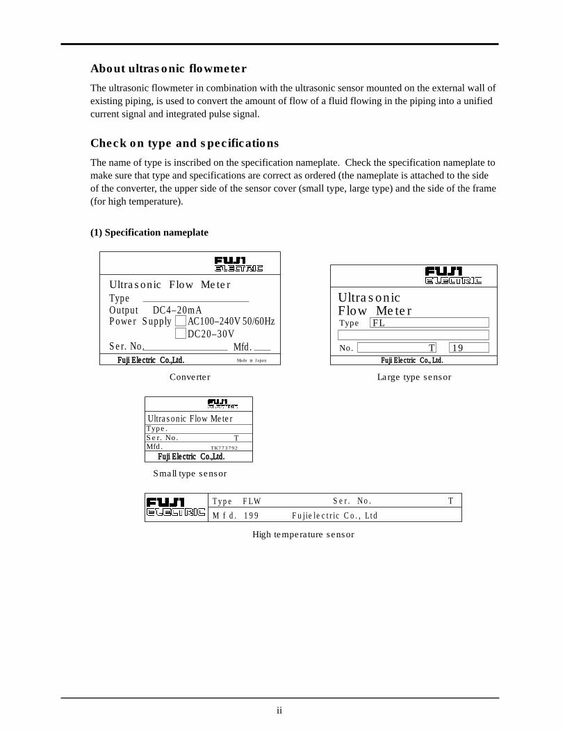
The name of type is inscribed on the specification nameplate. Check the specification nameplate tomake sure that type and specifications are correct as ordered (the nameplate is attached to the sideof the converter, the upper side of the sensor cover (small type, large type) and the side of the frame(for high temperature).
(1) Specification nameplate
Ultrasonic Flow MeterUltrasonicFlow MeterType FL
T 19No.
Type
Power SupplyOutput DC4–20mA
Ser. No.Fuji Electric Co.,Ltd.
Fuji Electric Co.,Ltd.
Fuji Electric Co., Ltd.
Mfd.
AC100–240V 50/60HzDC20–30V
Made in Japan
Ultrasonic Flow Meter
T y p e F L WM f d . 1 9 9 F u j i e l e c t r i c C o . , L t d
S e r . N o . T
Type.Ser. No. T
TK773792Mfd.
Converter
Small type sensor
High temperature sensor
Large type sensor
iii
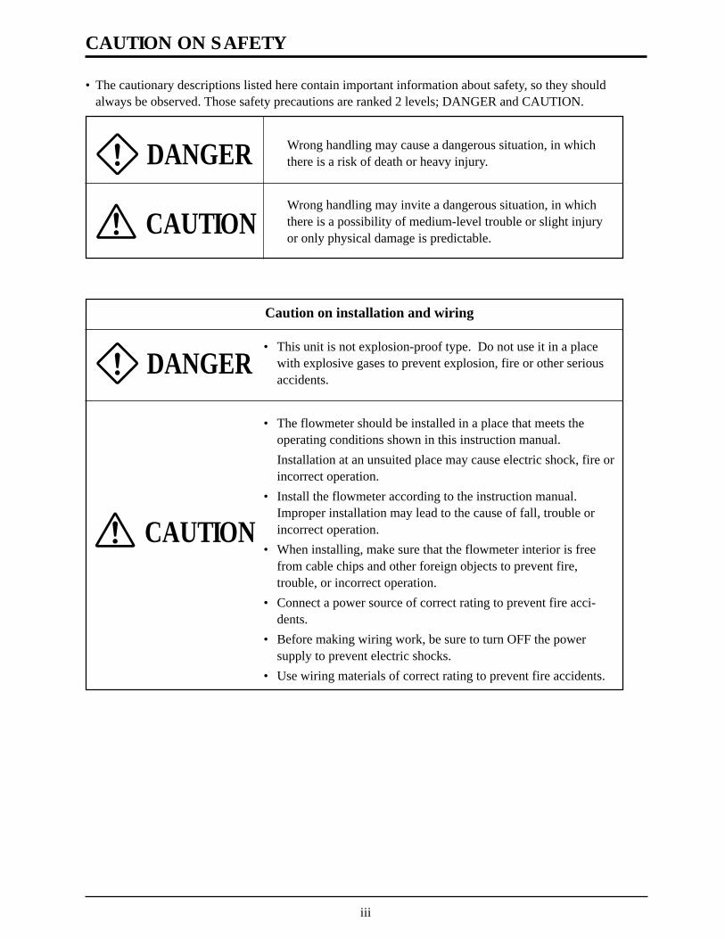
• The cautionary descriptions listed here contain important information about safety, so they shouldalways be observed. Those safety precautions are ranked 2 levels; DANGER and CAUTION.
Wrong handling may cause a dangerous situation, in whichthere is a risk of death or heavy injury.
Wrong handling may invite a dangerous situation, in whichthere is a possibility of medium-level trouble or slight injuryor only physical damage is predictable.
Caution on installation and wiring
• This unit is not explosion-proof type. Do not use it in a placewith explosive gases to prevent explosion, fire or other seriousaccidents.
• The flowmeter should be installed in a place that meets theoperating conditions shown in this instruction manual.Installation at an unsuited place may cause electric shock, fire orincorrect operation.
• Install the flowmeter according to the instruction manual.Improper installation may lead to the cause of fall, trouble orincorrect operation.
• When installing, make sure that the flowmeter interior is freefrom cable chips and other foreign objects to prevent fire,trouble, or incorrect operation.
• Connect a power source of correct rating to prevent fire acci-dents.
• Before making wiring work, be sure to turn OFF the powersupply to prevent electric shocks.
• Use wiring materials of correct rating to prevent fire accidents.
CAUTION
DANGER
CAUTION
DANGER
CAUTION ON SAFETY
iv
PREFACE........................................................................................................................................ i
CAUTION ON SAFETY ............................................................................................................... v
CONTENTS ................................................................................................................................. vii
1. OPERATING PARTS AND THEIR FUNCTIONS............................................................... 1
2. MOUNTING OF CONVERTER ............................................................................................ 22.1 Selection of mounting place ....................................................................................................... 2
2.2 Mounting method ....................................................................................................................... 2
2.3 Outline diagram (unit: in.) ......................................................................................................... 3
3. WIRING OF THE CONVERTER .......................................................................................... 43.1 Before wiring ............................................................................................................................. 4
3.2 Wiring ........................................................................................................................................ 4
3.3 Treatment of the wiring port ...................................................................................................... 4
3.4 Wiring to terminals .................................................................................................................... 5
4. OPERATION AND WORKS ................................................................................................. 64.1 Before operation ......................................................................................................................... 6
4.2 Power ON and status .................................................................................................................. 7
5. SETTING OF PARAMETERS .............................................................................................. 85.1 Outline of operating procedures ................................................................................................. 8
5.2 Description of key operation ...................................................................................................... 9
5.3 List of setting items .................................................................................................................. 11
5.4 Setting of parameters ............................................................................................................... 125.4 (1) Setting of piping specifications ................................................................................... 125.4 (2) Setting of analog output range ..................................................................................... 145.4 (3) Setting of analog output limit ...................................................................................... 165.4 (4) Setting of burn-out ....................................................................................................... 175.4 (5) Setting of damping....................................................................................................... 185.4 (6) Zero adjustment ........................................................................................................... 195.4 (7) Setting of measurement display specifications ............................................................ 205.4 (8) Low flow output cut .................................................................................................... 215.4 (9) Setting of integrated output unit and constant ............................................................. 225.4 (10) Setting of integral preset value .................................................................................... 235.4 (11) Setting of integration switch ........................................................................................ 245.4 (12) Selection of integral pulse output pulse width............................................................. 255.4 (13) Setting of measured value high and low limit switch .................................................. 265.4 (14) Setting of status output ................................................................................................ 275.4 (15) Calibration of measured value ..................................................................................... 285.4 (16) Switch of measurement unit system ............................................................................ 29
CONTENTS
v
5.4 (17) Selection of language (English/Japanese) ................................................................... 305.4 (18) Analog output check .................................................................................................... 315.4 (19) Analog output calibration ............................................................................................ 325.4 (20) Status output check ...................................................................................................... 335.4 (21) Test mode ..................................................................................................................... 34
6. MAINTENANCE AND INSPECTION ............................................................................... 356.1 Maintenance ............................................................................................................................. 35
6.2 Inspection ................................................................................................................................. 35
7. TROUBLESHOOTING ........................................................................................................ 367.1 How to confirm normal operation ............................................................................................ 36
7.1 (1) When checking by LCD indicator ............................................................................... 367.1 (2) LCD indication when power turned ON...................................................................... 367.1 (3) Detail check for abnormal status ................................................................................. 37
7.2 Faults and remedies .................................................................................................................. 387.2 (1) LCD display abnormal ................................................................................................. 387.2 (2) Key abnormal .............................................................................................................. 387.2 (3) Measured value abnormal ............................................................................................ 397.2 (4) Analog output abnormal .............................................................................................. 427.2 (5) Remedy for hardware fault .......................................................................................... 42
8. MOUNTING METHOD ....................................................................................................... 438.1 Mounting of sensor .................................................................................................................. 43
8.1 (1) Mounting procedure of sensor ..................................................................................... 438.1 (2) Selection of mounting place ........................................................................................ 448.1 (3) Selection of mounting method ..................................................................................... 458.1 (4) Processing of sensor mounting surface ....................................................................... 458.1 (5) Determination of mounting position (with Z method for large and small types) ........ 468.1 (6) Cable end treatment ..................................................................................................... 478.1 (7) Connection of cable to small type sensor .................................................................... 488.1 (8) Mounting of small type sensor on pipe ....................................................................... 498.1 (9) Assembling procedure of the sensor ............................................................................ 518.1 (10) Connection of cable to large type sensor ..................................................................... 528.1 (11) Mounting of large type sensor on pipe ........................................................................ 538.1 (12) Mounting of high temperature sensor on pipe ............................................................. 54
APPENDIX 1. SPECIFICATIONS.......................................................................................... A-1
APPENDIX 2. HOW TO MAKE GAUGE PAPER ................................................................ B-1
APPENDIX 3. COMPOSITION OF KEY OPERATION ....................................................... C-1
APPENDIX 4. PIPING DATA ................................................................................................ D-1

ULTRASONIC FLOW METER
PIPE
7 8 9 0 FUNK ESC
ENTER
OUTPUT DAMP ZERO
FLOW SW
4 5 6TOTAL CUT OFF DISP
STATUS
1 2 3CAL SYSTEM CHECK
6
1
54
3
2
1
I-out TR-out1 DOWN STRUP STR
2 3 4 5 6 7
GND
8
HF
9
GND
SH SH
10
HF
1
L N
AC100–240V
2 3
TR-out2
Black
Total or Status Output(Transister)
Analog Output
Green
Confirm converter power specificationsbefore connecting.
To Downstream SensorTo Upstream Sensor
White
White
BlackGreen
1
DC20–30V
2 3
1
1. OPERATING PARTS AND THEIR FUNCTIONS
The names and funcitons of parts of the converter are as follows.
Names of parts of converter
Item Description1 Wiring port Wiring port for power cable and signal cable2 Data indicator Liquid crystal indicator for measurement data and set values3 Key board Used for setting the conditions of adjustments and measurements.4 Main board terminal block Used for connecting signal cables from sensor.
Used for connection of signal cables for analog output and status output.5 Power terminal block Used for connecting power cable.6 Parameter table Used for entering setting data.
2
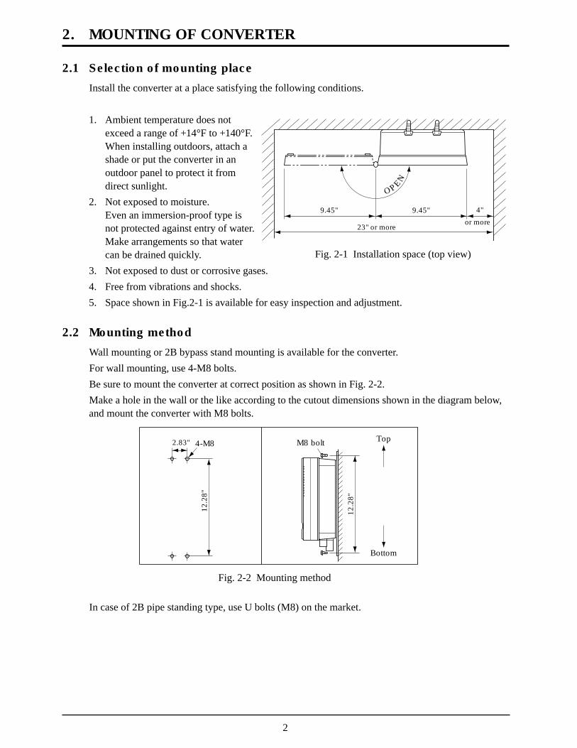
2.1 Selection of mounting place
Install the converter at a place satisfying the following conditions.
1. Ambient temperature does notexceed a range of +14°F to +140°F.When installing outdoors, attach ashade or put the converter in anoutdoor panel to protect it fromdirect sunlight.
2. Not exposed to moisture.Even an immersion-proof type isnot protected against entry of water.Make arrangements so that watercan be drained quickly.
3. Not exposed to dust or corrosive gases. 4. Free from vibrations and shocks. 5. Space shown in Fig.2-1 is available for easy inspection and adjustment.
2.2 Mounting method
Wall mounting or 2B bypass stand mounting is available for the converter.For wall mounting, use 4-M8 bolts.Be sure to mount the converter at correct position as shown in Fig. 2-2.Make a hole in the wall or the like according to the cutout dimensions shown in the diagram below,and mount the converter with M8 bolts.
2. MOUNTING OF CONVERTER
Fig. 2-1 Installation space (top view)
Fig. 2-2 Mounting method
In case of 2B pipe standing type, use U bolts (M8) on the market.
OPEN
9.45" 9.45" 4"
or more23" or more
312
M8 bolt Top
Bottom
312
2.83"
12.2
8"
12.2
8"
4-M8
3
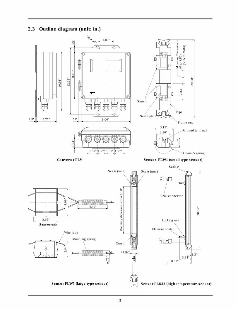
2.3 Outline diagram (unit: in.)
Converter FLV Sensor FLW1 (small type sensor)
Sensor FLD32 (high temperature sensor)Sensor FLW5 (large type sensor)
3333
530
Locking unit
Element holder
Cursor
Mou
ntin
g di
men
sion
s 0
to 3
30
Scale (inch)
BNC connector
Scale (mm)Saddle
Sensor
Name plate
Chain & spring
Frame end
Ground terminal
Pipe
(50A
to 2
50A
)
510
Mou
ntin
g di
men
sion
s(0
to 2
50)
72
Sensor unit
Wire rope
Mounting spring
104
62
1/8" 3.75"
10.9
1"
.79"
12.2
8"8.
66"
.55" 9.06"
2.83"
1.57" 1.57" 1.57" 1.57"
1.54
"
20.0
8"
2.83
"
2.36"
3.15"
1.57
"
20.8
7"
4.09
"
Mou
ntin
g di
men
sion
s 0
to 1
3.0"
1.3"
3.66"
4.49"
2.44
"
ø.75
"
ø1.02"1.3"
3.54"8.07"
.08-ø.35"
Mou
ntin
g D
imen
sion
s(0
to 9
.85)
2"
4
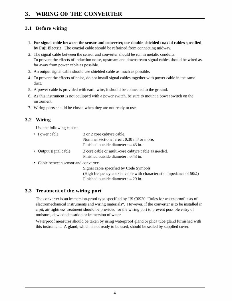
3.1 Before wiring
1. For signal cable between the sensor and converter, use double-shielded coaxial cables specifiedby Fuji Electric. The coaxial cable should be refrained from connecting midway.
2. The signal cable between the sensor and converter should be run in metalic conduits.To prevent the effects of induction noise, upstream and downstream signal cables should be wired asfar away from power cable as possible.
3. An output signal cable should use shielded cable as much as possible. 4. To prevent the effects of noise, do not install signal cables together with power cable in the same
duct. 5. A power cable is provided with earth wire, it should be connected to the ground. 6. As this instrument is not equipped with a power switch, be sure to mount a power switch on the
instrument. 7. Wiring ports should be closed when they are not ready to use.
3.2 Wiring
Use the following cables:• Power cable: 3 or 2 core cabtyre cable,
Nominal sectional area : 0.30 in.2 or more,Finished outside diameter : ø.43 in.
• Output signal cable: 2 core cable or multi-core cabtyre cable as needed.Finished outside diameter : ø.43 in.
• Cable between sensor and converter:Signal cable specified by Code Symbols(High frequency coaxial cable with characteristic impedance of 50W)Finished outside diameter : ø.29 in.
3.3 Treatment of the wiring port
The converter is an immersion-proof type specified by JIS C0920 “Rules for water-proof tests ofelectromechanical instruments and wiring materials“. However, if the converter is to be installed ina pit, air tightness treatment should be provided for the wiring port to prevent possible entry ofmoisture, dew condensation or immersion of water.Waterproof measures should be taken by using waterproof gland or plica tube gland furnished withthis instrument. A gland, which is not ready to be used, should be sealed by supplied cover.
3. WIRING OF THE CONVERTER
5
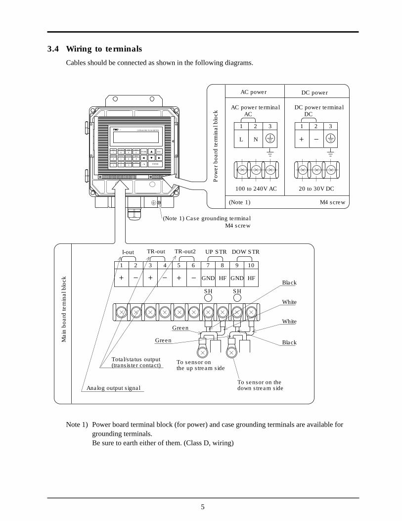
3.4 Wiring to terminals
Cables should be connected as shown in the following diagrams.
ULTRASONIC FLOW METER
PIPE
7 8 9 0 FUNK ESC
ENTER
OUTPUT DAMP ZERO
FLOW SW
4 5 6TOTAL CUT OFF DISP
STATUS
1 2 3CAL SYSTEM CHECK
1
AC
2 3
L N
100 to 240V AC
AC power terminal
AC power
1
DC
2 3
20 to 30V DC
DC power terminal
DC power
Pow
er b
oard
term
inal
blo
ck
1 2 3 4 5 6 7
GND
8
HF
9
GND
SH SH
10
HFBlack
Total/status output(transister contact)
Analog output signal
Green
White
White
BlackGreen
M4 screw(Note 1)
(Note 1) Case grounding terminalM4 screw
I-out TR-out TR-out2 DOW STRUP STR
Mai
n bo
ard
tem
inal
blo
ck
To sensor onthe up stream side
To sensor on thedown stream side
Note 1) Power board terminal block (for power) and case grounding terminals are available forgrounding terminals.Be sure to earth either of them. (Class D, wiring)
6
4.1 Before operation
Check the following before starting operation.
1. Power
Power check See Item 4.2 (1)
2. Wiring
1) Check of main board terminal block2) Check of power board terminal block See Item 3.43) Check of grounding terminal
3. Piping
1) Check that a piping is filled with fluid.2) Check that there is no problem when water stops or flows.
4. OPERATION AND WORKS
}

7
4.2 Power ON and status1. Power specification
1) AC powerUse power supply of 100 to 240VAC ±10% (50/60 Hz).2) DC powerA power of 20V to 30V DC is available.
2. Power ON
When the instrument is turned on, the following data are displayed on the LCD after making aself-check of the devices.The numerical values and symbols being displayed are as described below:
F L V - 2 S Y S T E M
V e r F L. V 2
B A C K PU M E M O YR
L O D I N GA
S t a b l ii t y W i t !a
Load parameters and data fromnon-volatile memory
Preparation to be taken until the measuringconditions are met.
Measuring screen
Flow display (See Item 5.4 (7))Flow direction
Display of integration, flow velocity and range %(See Item 5.4 (7))
Status display (See Item 7.1. (1))
If the upstream and downstream sensors are connected reversely,a symbol "—" appears on the LCD.
0 0 0. 0 m / Rs
. 00 0 0 m / s3

8
5. SETTING OF PARAMETERS
5.1 Outline of operating procedures
Proceed to the following procedure before starting measurements.
Chapter 3 Installation and wiringof converter
Chapter 4 Power ON
5.4 (1) Check of pipingspecification
5.4 (1) Input of pipingspecification
Chapter 8 Installation of sensor
Zero adjustment
Chapter 7 Troubleshooting
Output specification settingSystem settingIntegration specification settingFlow switch settingMeasuring display specification settingDamping settingLow flow cut settingOutput compensation settingStatus output setting
Measurement
Chapter 6 Maintenance and check
NG
OK
Measurement error
Measurement OK
5.4 (6)
9
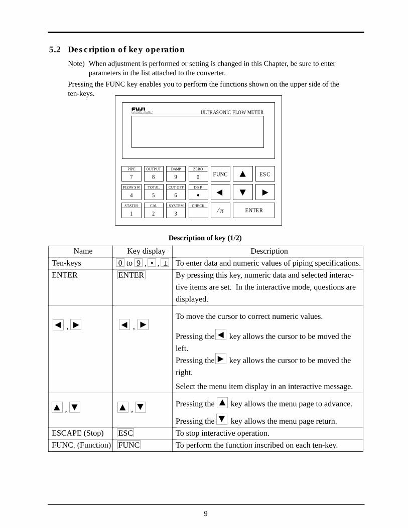
5.2 Description of key operation
Note) When adjustment is performed or setting is changed in this Chapter, be sure to enterparameters in the list attached to the converter.
Pressing the FUNC key enables you to perform the functions shown on the upper side of theten-keys.
ULTRASONIC FLOW METER
PIPE
7 8 9 0 FUNC ESC
ENTER
OUTPUT DAMP ZERO
FLOW SW
4 5 6TOTAL CUT OFF DISP
STATUS
1 2 3CAL SYSTEM CHECK
Description of key (1/2)
NameTen-keysENTER
,
,
ESCAPE (Stop)FUNC. (Function)
Key display0 to 9 , • , ±ENTER
,
,
ESCFUNC
DescriptionTo enter data and numeric values of piping specifications.By pressing this key, numeric data and selected interac-tive items are set. In the interactive mode, questions aredisplayed.
To move the cursor to correct numeric values.
Pressing the key allows the cursor to be moved theleft.Pressing the key allows the cursor to be moved theright.
Select the menu item display in an interactive message.
Pressing the key allows the menu page to advance.
Pressing the key allows the menu page return.To stop interactive operation.To perform the function inscribed on each ten-key.
10
Key display/pi
FUNC PIPEFUNCOUTPUTFUNCDAMPFUNC ZEROFUNC DISP
FUNCCUT OFFFUNCTOTALFUNCFLOW SWFUNCSTATUSFUNC CAL
FUNCSYSTEMFUNC CHECK
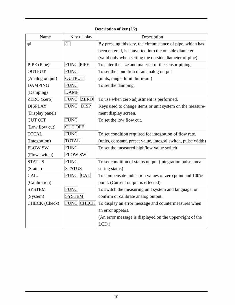
Description of key (2/2)
Name
PIPE (Pipe)OUTPUT(Analog output)DAMPING(Damping)ZERO (Zero)DISPLAY(Display panel)CUT OFF(Low flow cut)TOTAL(Integration)FLOW SW(Flow switch)STATUS(Status)CAL.(Calibration)SYSTEM(System)CHECK (Check)
DescriptionBy pressing this key, the circumstance of pipe, which hasbeen entered, is converted into the outside diameter.(valid only when setting the outside diameter of pipe)To enter the size and material of the sensor piping.To set the condition of an analog output(units, range, limit, burn-out)To set the damping.
To use when zero adjustment is performed.Keys used to change items or unit system on the measure-ment display screen.To set the low flow cut.
To set condition required for integration of flow rate.(units, constant, preset value, integral switch, pulse width)To set the measured high/low value switch
To set condition of status output (integration pulse, mea-suring status)To compensate indication values of zero point and 100%point. (Current output is effected)To switch the measuring unit system and language, orconfirm or calibrate analog output.To display an error message and countermeasures whenan error appears.(An error message is displayed on the upper-right of theLCD.)
/pi

11
5.3 List of setting items
Measurement screen Piping specifications ----------------------------------- See Item 5.4 (1)( FUNC PIPE )
Setting of output Range ------------------------ See Item 5.4 (2)( FUNC OUTPUT ) Output limit ----------------- See Item 5.4 (3)
Burn-out--------------------- See Item 5.4 (4)
Damping------------------------------------------------- See Item 5.4 (5)( FUNC DAMP )
Zero adjustment ---------------------------------------- See Item 5.4 (6)( FUNC ZERO )
Display setting ------------------------------------------ See Item 5.4 (7)( FUNC DISP )
Low flow cut -------------------------------------------- See Item 5.4 (8)( FUNC CUT OFF )
Integration Integration unit and constant ----- See Item 5.4 (9)( FUNC TOTAL ) Integral preset -------------- See Item 5.4 (10)
Integral switch ------------- See Item 5.4 (11)Integral pulse width ------- See Item 5.4 (12)
Flow switch --------------------------------------------- See Item 5.4 (13)( FUNC FLOW SW )
Status output -------------------------------------------- See Item 5.4 (14)( FUNC STATUS )
Output compensation ---------------------------------- See Item 5.4 (15)( FUNC CAL )
System Measuring unit ------------ See Item 5.4 (16)( FUNC SYSTEM ) Switch of language ------- See Item 5.4 (17)
Confirmation analog output --- See Item 5.4 (18)Analog output calibration ----- See Item 5.4 (19)Status output check ------- See Item 5.4 (20)Test mode ------------------ See Iitem 5.4 (21)
12
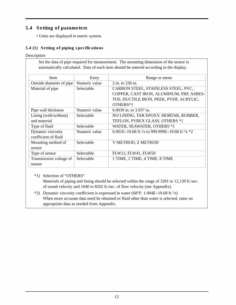
5.4 Setting of parameters
• Units are displayed in metric system.
5.4 (1) Setting of piping specifications
DescriptionSet the data of pipe required for measurement. The mounting dimension of the sensor isautomatically calculated. Data of each item should be entered according to the display.
ItemOutside diameter of pipeMaterial of pipe
Pipe wall thicknessLining (with/without)and materialType of fluidDynamic viscositycoefficient of fluidMounting method ofsensorType of sensorTransmission voltage ofsensor
EntryNumeric valueSelectable
Numeric valueSelectable
SelectableNumeric value
Selectable
SelectableSelectable
Range or menu2 in. to 236 in.CARBON STEEL, STAINLESS STEEL, PVC,COPPER, CAST IRON, ALUMINUM, FRP, ASBES-TOS, DUCTILE IRON, PEEK, PVDF, ACRYLIC,OTHERS*10.0039 in. to 3.937 in.NO LINING, TAR EPOXY, MORTAR, RUBBER,TEFLON, PYREX GLASS, OTHERS *1WATER, SEAWATER, OTHERS *10.001E-19.68 ft.2/s to 999.999E-19.68 ft.2/s *2
V METHOD, Z METHOD
FLW12, FLW41, FLW501 TIME, 2 TIME, 4 TIME, 8 TIME
*1) Selection of “OTHERS”Materials of piping and lining should be selected within the range of 3281 to 12,139 ft./sec.of sound velocity and 1640 to 8202 ft./sec. of flow velocity (see Appendix).
*2) Dynamic viscosity coefficient is expressed in water (68°F: 1.004E-19.68 ft.2/s)When more accurate data need be obtained or fluid other than water is selected, enter anappropriate data as needed from Appendix.
13
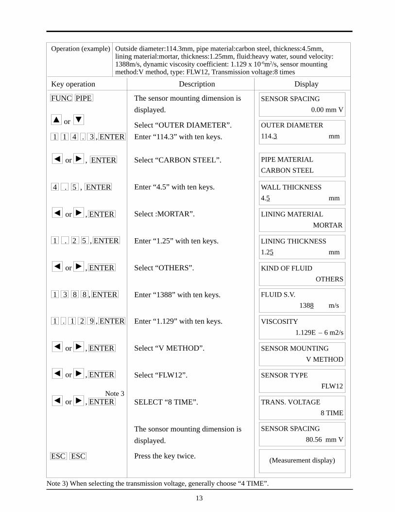
Operation (example) Outside diameter:114.3mm, pipe material:carbon steel, thickness:4.5mm,lining material:mortar, thickness:1.25mm, fluid:heavy water, sound velocity:1388m/s, dynamic viscosity coefficient: 1.129 x 10⁻⁶m2/s, sensor mountingmethod:V method, type: FLW12, Transmission voltage:8 times
Key operation
FUNC PIPE
or
1 1 4 . 3 , ENTER
or , ENTER
4 . 5 , ENTER
or , ENTER
1 . 2 5 , ENTER
or , ENTER
1 3 8 8 , ENTER
1 . 1 2 9 , ENTER
or , ENTER
or , ENTER
or , ENTER
ESC ESC
Description
The sensor mounting dimension isdisplayed.
Select “OUTER DIAMETER”.Enter “114.3” with ten keys.
Select “CARBON STEEL”.
Enter “4.5” with ten keys.
Select :MORTAR”.
Enter “1.25” with ten keys.
Select “OTHERS”.
Enter “1388” with ten keys.
Enter “1.129” with ten keys.
Select “V METHOD”.
Select “FLW12”.
SELECT “8 TIME”.
The sonsor mounting dimension isdisplayed.
Press the key twice.
SENSOR SPACING 0.00 mm V
OUTER DIAMETER114.3 mm
PIPE MATERIALCARBON STEEL
WALL THICKNESS4.5 mm
LINING MATERIALMORTAR
LINING THICKNESS1.25 mm
KIND OF FLUIDOTHERS
FLUID S.V.1388 m/s
VISCOSITY1.129E – 6 m2/s
SENSOR MOUNTINGV METHOD
SENSOR TYPEFLW12
TRANS. VOLTAGE8 TIME
SENSOR SPACING80.56 mm V
(Measurement display)
Display
Note 3) When selecting the transmission voltage, generally choose “4 TIME”.
Note 3
14
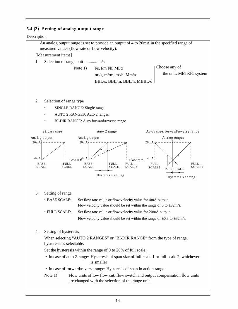
5.4 (2) Setting of analog output range
DescriptionAn analog output range is set to provide an output of 4 to 20mA in the specified range ofmeasured values (flow rate or flow velocity).
[Measurement items]1. Selection of range unit ............ m/s
l/s, l/m l/h, Ml/dm3/s, m3/m, m3/h, Mm3/dBBL/s, BBL/m, BBL/h, MBBL/d
2. Selection of range type• SINGLE RANGE: Single range
• AUTO 2 RANGES: Auto 2 ranges
• BI-DIR RANGE: Auto forward/reverse range
3. Setting of range• BASE SCALE: Set flow rate value or flow velocity value for 4mA output.
Flow velocity value should be set within the range of 0 to ±32m/s.
• FULL SCALE: Set flow rate value or flow velocity value for 20mA output.
Flow velocity value should be set within the range of ±0.3 to ±32m/s.
4. Setting of hysteresisWhen selecting “AUTO 2 RANGES” or “BI-DIR.RANGE” from the type of range,hysteresis is selectable.Set the hysteresis within the range of 0 to 20% of full scale.• In case of auto 2-range: Hysteresis of span size of full-scale 1 or full-scale 2, whichever
is smaller• In case of forward/reverse range: Hysteresis of span in action range
Note 1) Flow units of low flow cut, flow switch and output compensation flow unitsare changed with the selection of the range unit.
Analog output
Single range
20mA
4mA
BASESCALE
FULLSCALE
Flow rate
Analog output
Auto 2 range
20mA
4mA
BASESCALE
FULLSCALE1
Flow rateFULLSCALE2
Hysteresis setting
Analog output
Auto range, forward/reverse range
20mA
4mA
FULLSCALE2
FULLSCALE1
Hysteresis setting
BASE SCALE
Note 1) Choose any ofthe unit: METRIC system
15
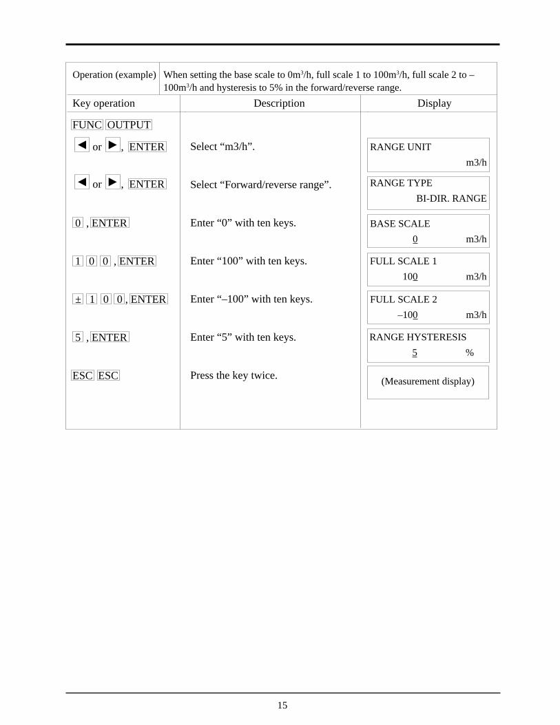
Operation (example) When setting the base scale to 0m3/h, full scale 1 to 100m3/h, full scale 2 to –100m3/h and hysteresis to 5% in the forward/reverse range.
Key operation
FUNC OUTPUT
or , ENTER
or , ENTER
0 , ENTER
1 0 0 , ENTER
± 1 0 0 , ENTER
5 , ENTER
ESC ESC
Description
Select “m3/h”.
Select “Forward/reverse range”.
Enter “0” with ten keys.
Enter “100” with ten keys.
Enter “–100” with ten keys.
Enter “5” with ten keys.
Press the key twice.
RANGE UNIT m3/h
RANGE TYPEBI-DIR. RANGE
BASE SCALE0 m3/h
FULL SCALE 1100 m3/h
FULL SCALE 2–100 m3/h
RANGE HYSTERESIS5 %
(Measurement display)
Display
16
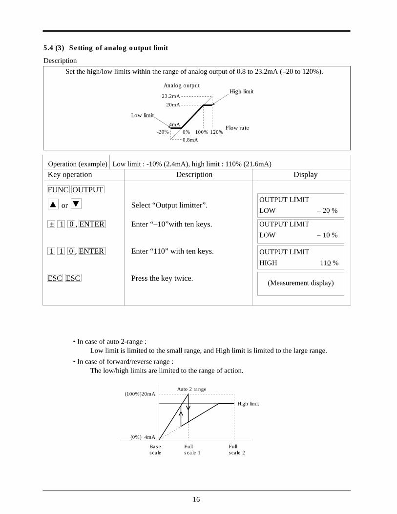
5.4 (3) Setting of analog output limit
DescriptionSet the high/low limits within the range of analog output of 0.8 to 23.2mA (-20 to 120%).
23.2mA
20mA
4mA0% 100% 120%0.8mA
-20%
High limit
Low limit
Flow rate
Analog output
Operation (example) Low limit : -10% (2.4mA), high limit : 110% (21.6mA)Key operation
FUNC OUTPUT
or
± 1 0 , ENTER
1 1 0 , ENTER
ESC ESC
Description
Select “Output limitter”.
Enter “–10”with ten keys.
Enter “110” with ten keys.
Press the key twice.
OUTPUT LIMITLOW – 20 %
OUTPUT LIMITLOW – 10 %
OUTPUT LIMITHIGH 110 %
(Measurement display)
Display
High limit
Auto 2 range(100%)20mA
(0%) 4mA
Fullscale 2
Fullscale 1
Basescale
• In case of auto 2-range :Low limit is limited to the small range, and High limit is limited to the large range.
• In case of forward/reverse range :The low/high limits are limited to the range of action.

17
5.4 (4) Setting of burn-out
DescriptionWhen the pipe is empty of fluid or when air bubbles are contained in fluid, the flow rate cannot be measured correctly. In such a case, the analog output needs to be set to “HOLD”,“HIGH” limit or “LOW” limit. A burnout timer is used to set the time needed for burnout.(Setting items)• HOLD : Measured value is held• HIGH : 120%t output (23.2mA) is obtained.• LOW : -20% output (0.8mA) is obtained.• Zero : 0 % output (4.0mA) is obtained.• NOT USED : Not used.• Liquid crystal display : Measured value is held.• Integrated pulse output : Output stops Note)• Internal integration : Integration stops Note)Note) Integrated pulse output and internal integration is integrated until the burnout timer is
energized.
Operation (example) When setting the burnout to the “LOW” limit and burnout timer to 15seconds.
Key operation
FUNC OUTPUT
or
or , ENTER
1 5 , ENTER
ESC ESC
Description
Select “Burn-out”.
Select “Low limit”.
Enter “15” with ten keys.
Press the key twice.
OUTPUT BURNOUTNOT USED
OUTPUT BURNOUTLOWER
(Measurement display)
Display
BURNOUT TIMER15 sec

18
5.4 (5) Setting of damping
DescriptionDamping is used to suppress fluctuation of measured values.The set value is a time constant (about 63% response time). (Setting range : 0 to 100 sec)
Unless otherwise specified in the order sheet, the setting time of damping is adjusted to 5 sec.
63%
TimeResponse time
Flow
rate
Operation (example) Change of set value to 20 sec.Key operation
FUNC DAMP
2 0 , ENTER
Description
Enter “20” with ten keys. DAMPING20 sec
(Measurement display)
Display

19
5.4 (6) Zero adjustment
DescriptionZero point of measured value is adjusted.(Setting items)• ZERO POINT ADJUST : Stop the flow of fluid and adjust zero point.
The zero pont is the state of measurement at set point.• ZERO POINT CLEAR : This setting is used when fluid will not stop flowing.
Adjusted zero point is cleared.
Operation (example) Zero point adjustment when fluid is in stop mode.Key operation
FUNC ZERO
or , ENTER
Description
Select “Zero point adjustment”. ZERO MODESET ZERO
(Measurement display)
Display

20
5.4 (7) Setting of measurement display specifications
DescriptionSelect measured value from the following.
1. Setting of measurement display 1st lineSelect any one from the following 7 types for the 1st line display.
F : TOTAL : Forward integral valueR : TOTAL : Reverse integral valueTOTAL DIFF : Forward/reverse difference between integral valuesF : TOTAL PULSE : Forward integral pulse counterR : TOTAL PULSE : Reverse integral pulse counterFLOW VELOCITY : Instantaneous flow velocity [m/s]RANGE % : Ratio of analog output to range
2. Setting of decimal measurement display on 2nd lineOn the second display is instantaneous flow rate displayed.Select one from the following 12 units of flow rate.
l/s, l/m l/h, Ml/d, m3/s, m3/m, m3/h, Mm3/dBBL/s, BBL/m, BBL/h, MBBL/d
3. Setting of decimal point position of instantaneous flow rate displaySetting of digit display after the decimal point is available.
Select any one from the following.Position of decimal point (digit) Range of data display
00000000. : -99999999. to 0. to 99999999.0000000.0 : -9999999.9 to 0.0 to 9999999.9000000.00 : -999999.99 to 0.00 to 999999.9900000.000 : -99999.999 to 0.000 to 99999.9990000.0000 : -9999.9999 to 0.0000 to 9999.9999000.00000 : -999.99999 to 0.00000 to 999.9999900.000000 : -99.999999 to 0.000000 to 99.9999990.0000000 : -9.9999999 to 0.0000000 to 9.9999999
Display of integral value1. Display of forward/reverse integral values
Overflow markWhen the integral value exceeds the overflow mark.
Overflow times0 to 9, # (exceeding 9)
Integral value0 to 9999999
#
2. Display of forward/reverse difference between integral valuesDifference of integrated value = forward integral value - reverse integral value.Note : If any of integral values in the forward and reverse directions exceeds the overflow mark, ####### is displayed.
(metric system)}
21
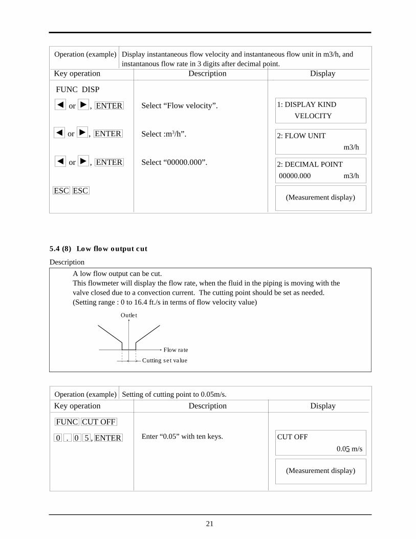
5.4 (8) Low flow output cut
DescriptionA low flow output can be cut.This flowmeter will display the flow rate, when the fluid in the piping is moving with thevalve closed due to a convection current. The cutting point should be set as needed.(Setting range : 0 to 16.4 ft./s in terms of flow velocity value)
Operation (example) Setting of cutting point to 0.05m/s.Key operation
FUNC CUT OFF
0 . 0 5 , ENTER
Description
Enter “0.05” with ten keys. CUT OFF
(Measurement display)
Display
Flow rate
Cutting set value
Outlet
0.05 m/s
Operation (example) Display instantaneous flow velocity and instantaneous flow unit in m3/h, andinstantanous flow rate in 3 digits after decimal point.
Key operation
FUNC DISP
or , ENTER
or , ENTER
or , ENTER
ESC ESC
Description
Select “Flow velocity”.
Select :m3/h”.
Select “00000.000”.
1: DISPLAY KINDVELOCITY
(Measurement display)
Display
2: FLOW UNITm3/h
2: DECIMAL POINT 00000.000 m3/h

22
5.4 (9) Setting of integrated output unit and constant
DescriptionIntegrated output unit is set to integrate measurement value (flow rate)Just after setting of measured value is completed, the pulse counter begins integration byclearing the previous integrated value.
1. Integrated unit.………Select one of the following 8 kinds of integral units.ml, l, m3, km3, Mm3, mBBL, BBL, kBBL (metric system)Note : When changing the integrated unit, integral constant value and integral preset
value are cleared.2. Integral constant
When the flow rate reaches the value set by the integral constant, integral pulse value isdisplayed on the measurement screen, and the integral pulse counter provides an output of 1pulse.Setting range : 0 to 9999999
Operation (example) Integrated output of 100m3
Key operation
FUNC TOTAL
or , ENTER
or , ENTER
1 0 0 , ENTER
ESC
or , ENTER
ESC ESC
Description
Display “TOTAL MODE”.
Select “m3”.
Enter “100” with ten keys.
Display “TOTAL MODE”.
Select “START”.
Press the key twice.
TOTAL UNITm3
(Measurement display)
Display
TOTAL RATE100 m3
TOTAL MODETOTAL STOP
TOTAL MODETOTAL STOP
TOTAL MODETOTAL RUN
Integral modeStop: Integration is stopped.Start: Integration is started (integral parameter can not be changed at a time of start).Reset: Integral value is set to the integral preset value, and integration is stopped.
When the flowmeter is restored from power interruption, it will be operated in the integral mode thatwas set before power interruption.[Note : If measurement is abnormal, refer to burnout setting for integration.]
23
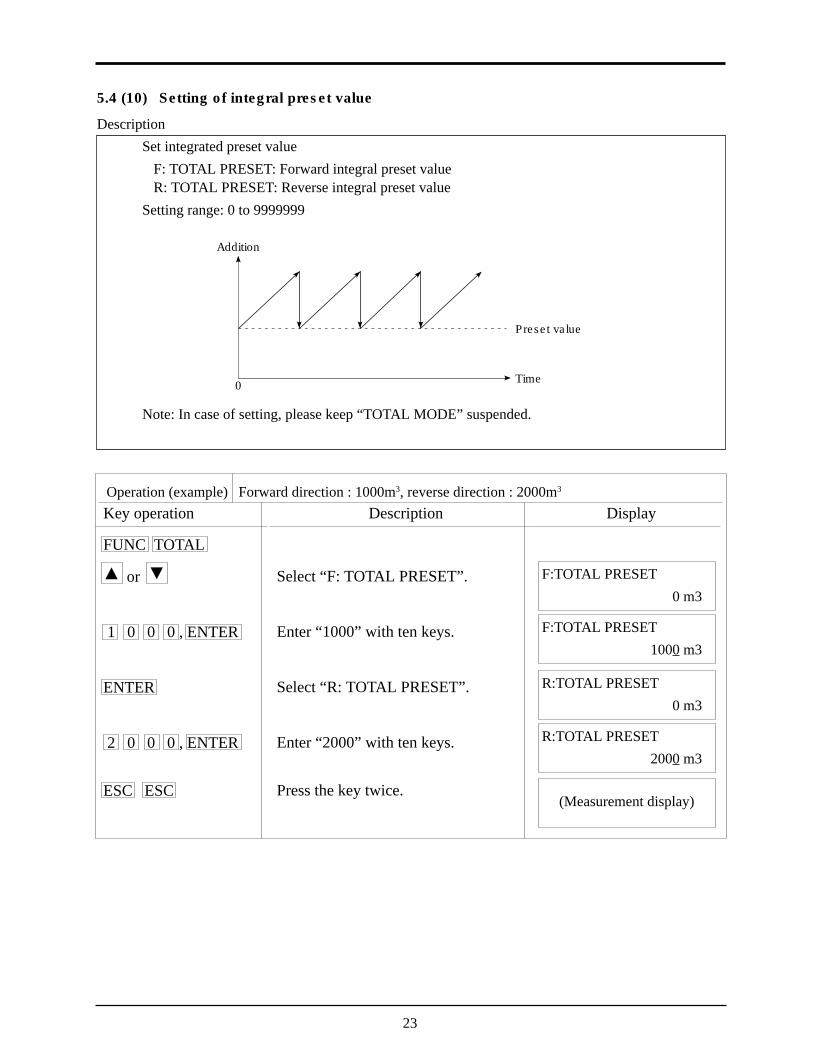
5.4 (10) Setting of integral preset value
DescriptionSet integrated preset value
F: TOTAL PRESET: Forward integral preset valueR: TOTAL PRESET: Reverse integral preset value
Setting range: 0 to 9999999
Operation (example) Forward direction : 1000m3, reverse direction : 2000m3
Key operation
FUNC TOTAL
or
1 0 0 0 , ENTER
ENTER
2 0 0 0 , ENTER
ESC ESC
Description
Select “F: TOTAL PRESET”.
Enter “1000” with ten keys.
Select “R: TOTAL PRESET”.
Enter “2000” with ten keys.
Press the key twice.
F:TOTAL PRESET0 m3
(Measurement display)
Display
Addition
0 Time
Preset value
F:TOTAL PRESET1000 m3
R:TOTAL PRESET0 m3
R:TOTAL PRESET2000 m3
Note: In case of setting, please keep “TOTAL MODE” suspended.

24
5.4 (11) Setting of integration switch
DescriptionWhen an integral value exceeds the set value, the status output is provided.
F: TOTAL SW: Forward integration switchR: TOTAL SW: Reverse integration switch
Setting range: 0 to 9999999Note) When setting the status output, integration switch is valid only
when “F: TOTAL SW” or “R: TOTAL SW” is set.
Operation (example) Set value of forward integration switch :50000m3
Key operation
FUNC TOTAL
or
5 0 0 0 0 , ENTER
ESC ESC
Description
Select “TOTAL SW”.
Enter “50000” with ten keys.
Press the key twice.
F: TOTAL SW0 m3
(Measurement display)
Display
F: TOTAL SW50000 m3
Integration
Setting value
ONOFF
Contact output
Note: In case of setting, please keep “TOTAL MODE” suspended.

25
5.4 (12) Selection of integral pulse output pulse width
DescriptionThe following 2 types can be selected according to the counter connected.When setting status output, set the pulse width to use “F:TOTAL” or “R:TOTAL”.
• 50msec• 100msec
Operation (example) Pulse width: 100msec.Key operation
FUNC TOTAL
or
or , ENTER
Description
Select “Pulse width”.
Select “100msec”.
PULSE WIDTH50 msec
(Measurement display)
Display
PULSE WIDTH100 msec
Note: In case of setting, please keep “TOTAL MODE” suspended.
26
ON
OFF OFF
ON
High limitset value
Hysteresis
ON
OFF OFF
ON
Low limitset value
Hysteresis
105 ft./s
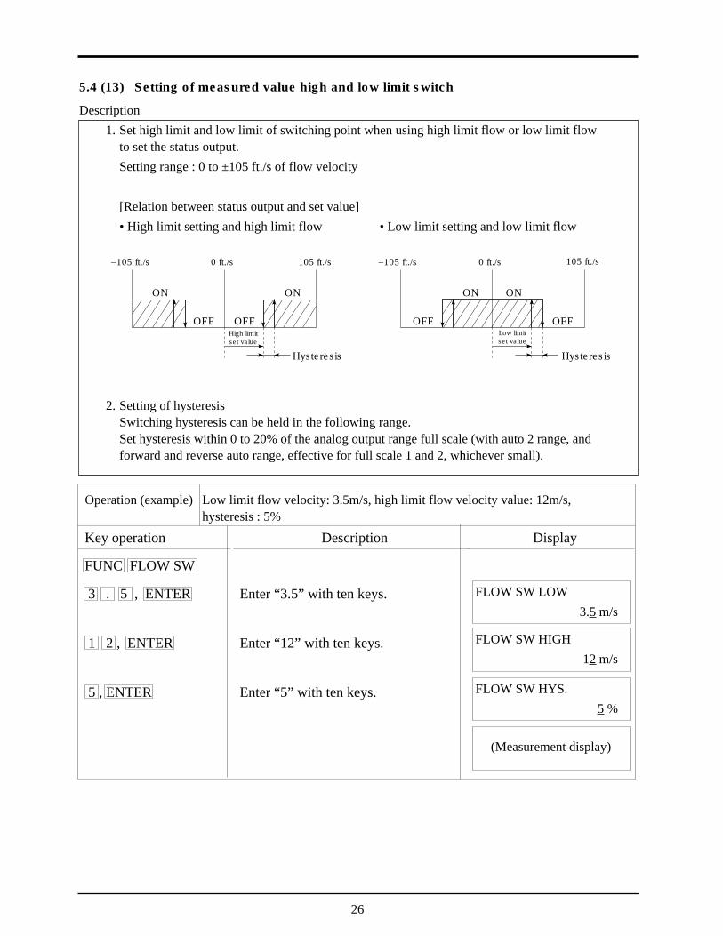
5.4 (13) Setting of measured value high and low limit switch
Description1. Set high limit and low limit of switching point when using high limit flow or low limit flow
to set the status output.Setting range : 0 to ±105 ft./s of flow velocity
[Relation between status output and set value]• High limit setting and high limit flow • Low limit setting and low limit flow
2. Setting of hysteresisSwitching hysteresis can be held in the following range.Set hysteresis within 0 to 20% of the analog output range full scale (with auto 2 range, andforward and reverse auto range, effective for full scale 1 and 2, whichever small).
Operation (example) Low limit flow velocity: 3.5m/s, high limit flow velocity value: 12m/s,hysteresis : 5%
Key operation
FUNC FLOW SW
3 . 5 , ENTER
1 2 , ENTER
5 , ENTER
Description
Enter “3.5” with ten keys.
Enter “12” with ten keys.
Enter “5” with ten keys.
FLOW SW LOW3.5 m/s
(Measurement display)
Display
FLOW SW HIGH12 m/s
FLOW SW HYS.5 %
–105 ft./s –105 ft./s 105 ft./s0 ft./s 0 ft./s

27
5.4 (14) Setting of status output
Description• When the status of setting or integral pulse is outputted, the contents of output is set.1. NOT USED : No output2. SIGNAL ERROR : ON at abnormal measurement3. F: TOTAL PULSE : Forward flow integral pulse4. R: TOTAL PULSE : Reverse flow integral pulse5. FLOW SW HIGH : ON when the flow rate is over the high limit set by flow switch.6. FLOW SW LOW : ON when the flow rate is below the low low limit set by
flow switch.7. F: TOTAL ALARM : ON when the flow rate is over the forward flow integration
switch.8. R: TOTAL ALARM : ON when the flow rate is below the reverse flow integra-
tion switch.
9. F: TOTAL OVERFLOW : ON when the forward flow integral value overflows.10. R: TOTAL OVERFLOW : ON when reverse flow integral value overflows.11. FULL SCALE 2 : ON at FULL SCALE 2 RANGE in analog output range status.12. R: FLOW DIRECTION : ON when the flow direction is reverse.13. RANGE OVER : ON when the set value of the output span exceeds the range
of -10 to 110%, or integral pulse output exceeds 5 pulse/sec.
14. BACK UP ABNORMAL : ON when the backup non-volatile memory is abnormal.• Setting of status output pulse mode
Normal: effective when status output is ON.Spot: effective when status output is OFF.
Operation (example) When setting the forward integral pulse and contact output in the normalmode.
Key operation
FUNC STATUS
or , ENTER
or , ENTER
or , ENTER
ESC
Description
Select “CHANNEL 1”.
Select “F: TOTAL”.
Select “Normal”.
(Continued on next page)
STATUS CHANELCHANNEL 1
Display
STATUS MODE : CH1NORMAL
STATUS SEL : CH1F : TOTAL
28
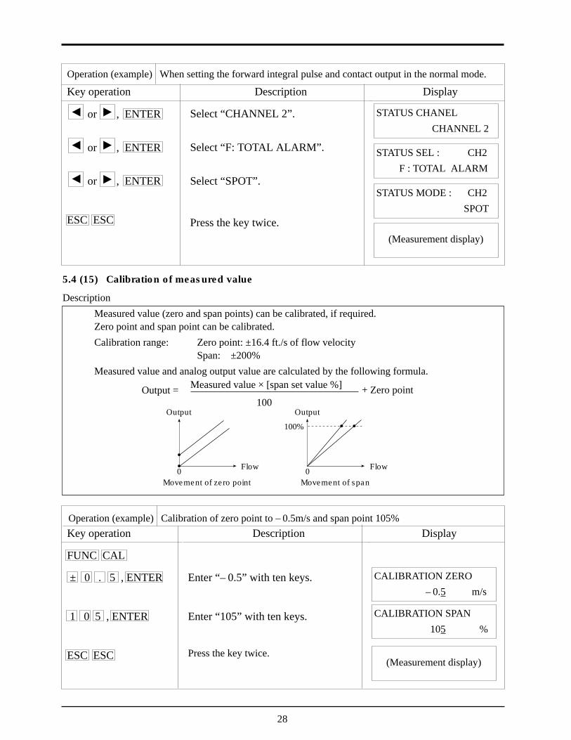
5.4 (15) Calibration of measured value
DescriptionMeasured value (zero and span points) can be calibrated, if required.Zero point and span point can be calibrated.Calibration range: Zero point: ±16.4 ft./s of flow velocity
Span: ±200%Measured value and analog output value are calculated by the following formula.
Operation (example) Calibration of zero point to – 0.5m/s and span point 105%Key operation
FUNC CAL
± 0 . 5 , ENTER
1 0 5 , ENTER
ESC ESC
Description
Enter “– 0.5” with ten keys.
Enter “105” with ten keys.
Press the key twice.
CALIBRATION ZERO– 0.5 m/s
(Measurement display)
Display
CALIBRATION SPAN105 %
Output = Measured value ´ [span set value %]
100+ Zero point
Output
0Movement of zero point
Output
0Movement of span
100%
Flow Flow
Operation (example) When setting the forward integral pulse and contact output in the normal mode.
Key operation
or , ENTER
or , ENTER
or , ENTER
ESC ESC
Description
Select “CHANNEL 2”.
Select “F: TOTAL ALARM”.
Select “SPOT”.
Press the key twice.
Display
STATUS CHANELCHANNEL 2
STATUS MODE : CH2SPOT
STATUS SEL : CH2F : TOTAL ALARM
(Measurement display)

29
5.4 (16) Switch of measurement unit system
DescriptionMeasurement units can be set in the two systems, metric system and inch system.(Setting contents)
• Metric systemPipe dimension ------------mmFlow velocity unit ---------m/sFlow rate unit -------------- l/s, l/m l/h Ml/d
m3/s, m3/m, m3/h, Mm3/dBBL/s, BBL/m, BBL/h, MBBL/d
Integration unit ------------ml, l, m3, km3, Mm3, mBBL, BBL, kBBL• English system
Pipe dimension ------------ inchFlow velocity unit --------- ft/sFlow rate unit --------------gal/s, gal/m, gal/h, gal/d
ft3/s, ft3/m, ft3/h, Mft3/dBBL/s, BBL/m, BBL/h, MBBL/d
Integration unit ------------gal, kgal, ft3, kft3, Mft3, mBBL, BBL, kBBL
Operation (example) Change of measurement unit to inch system
Key operation
FUNC SYSTEM
or , ENTER
ESC ESC
Description
Select “Inch system”.
Press the key twice.
SYSTEM OF UNITSENGLISH
(Measurement display)
Display
30
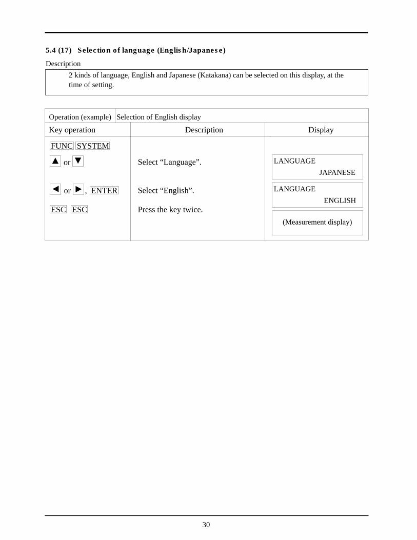
5.4 (17) Selection of language (English/Japanese)
Description2 kinds of language, English and Japanese (Katakana) can be selected on this display, at thetime of setting.
Operation (example) Selection of English display
Key operation
FUNC SYSTEM
or
or , ENTER
ESC ESC
Description
Select “Language”.
Select “English”.
Press the key twice.
LANGUAGEJAPANESE
(Measurement display)
Display
LANGUAGEENGLISH

31
5.4 (18) Analog output check
DescriptionCheck the analog output circuit.Check to make sure that the output values at -20% to 120% are 0.8mA to 23.2mA.Connect an ammeter to the Iout terminal as shown below.
Operation (example) Check of analog output of 4mA, 8mA, 12mA, 16mA, 20mAKey operation
FUNC SYSTEM
or
0 , ENTER
2 5 , ENTER
5 0 , ENTER
7 5 , ENTER
1 0 0 , ENTER
ESC ESC
Description
Select “Analog output check”.
Enter “0” with ten keys.[0% (4mA) check]
Enter “25” with ten keys.[25% (8mA) check]
Enter “50” with ten keys.[50% (12mA) check]
Enter “75” with ten keys.[75% (16mA) check]
Enter “100” with ten keys.[100% (20mA) check]
Press the key twice.
OUTPUT CHECK0 %
(Measurement display)
Display
OUTPUT CHECK0 %
Iout
Ammeter
TRout 1
1 2 3 4
OUTPUT CHECK25 %
OUTPUT CHECK50 %
OUTPUT CHECK75 %
OUTPUT CHECK100 %

32
5.4 (19) Analog output calibration
DescriptionThe analog output circuit is calibrated so that the measured flow rate is set to provide an output of4mA in the base scale and 20mA in the full scale.Calibration should be performed by connecting an ammeter to Iout terminal as shown below.
Operation (example) Calibration of output of 4mA, 20mAKey operation
FUNC SYSTEM
or
or , ENTER
(up) or (down)
(down) or (up), ENTER
(up) or (down)
(down) or (up), ENTER
ESC ESC
Description
Select “Analog output calibration”.
Select “Setting”.
Fine calibration
Coarse calibration
Fine calibration
Coarse calibration
Press the key twice.
OUTPUT ADJUSTSKIP
(Measurement display)
Display
OUTPUT ADJUSTSETTING
Iout
Ammeter
TRout 1
1 2 3 4
OUTPUT ADJUST20mA
}Ammeter shouldindicate 4mA.
}Ammeter shouldindicate 20mA.
OUTPUT ADJUST4mA
Note : After calibration is completed, set the calibration mode to Skip.
33
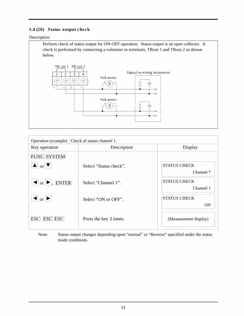
5.4 (20) Status output check
DescriptionPerform check of status output for ON-OFF operation. Status output is an open collector. Acheck is performed by connecting a voltmeter to terminals, TRout 1 and TRout 2 as shownbelow.
Operation (example) Check of status channel 1.Key operation
FUNC SYSTEM
or
or , ENTER
or
ESC ESC ESC
Description
Select “Status check”.
Select “Channel 1”.
Select “ON or OFF”.
Press the key 3 times.
STATUS CHECKChannel *
(Measurement display)
Display
STATUS CHECKChannel 1
STATUS CHECKON
TR out 1
Volt meter
TR out 2
1 2 3 4
Volt meter
V
V
Signal receiving instrument
Note: Status output changes depending upon “normal” or “Reverse” specified under the statusmode conditions.
34
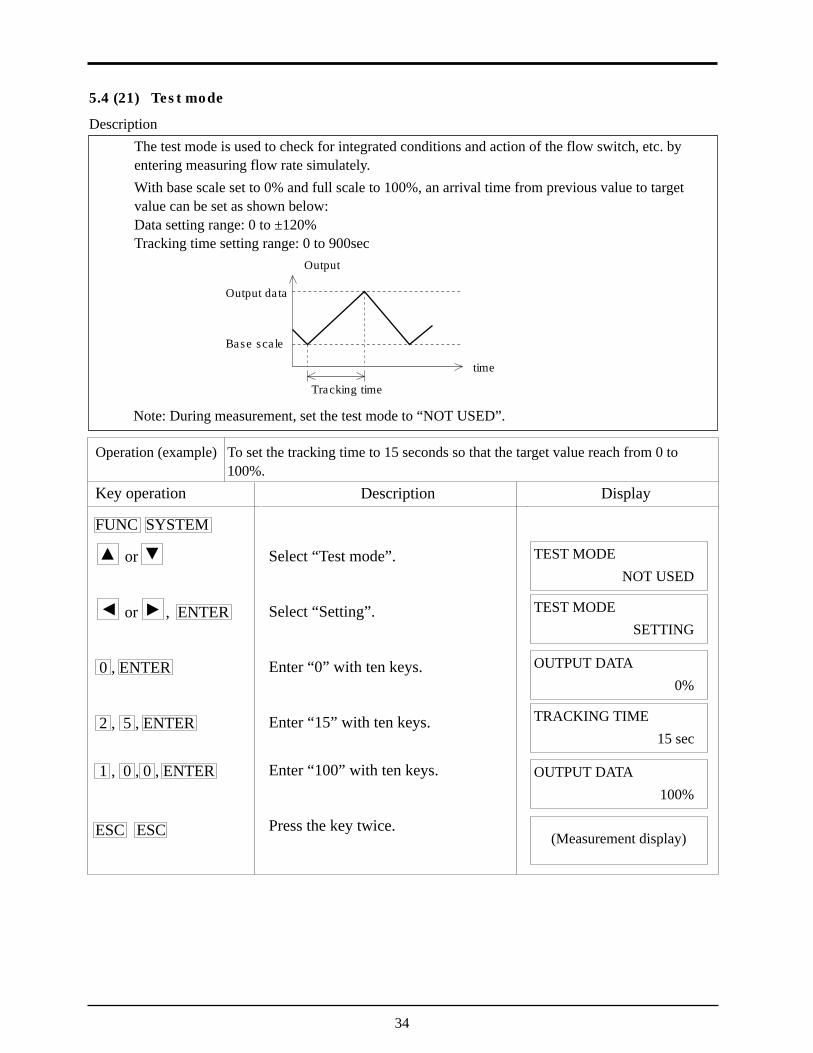
5.4 (21) Test mode
DescriptionThe test mode is used to check for integrated conditions and action of the flow switch, etc. byentering measuring flow rate simulately.With base scale set to 0% and full scale to 100%, an arrival time from previous value to targetvalue can be set as shown below:Data setting range: 0 to ±120%Tracking time setting range: 0 to 900sec
Operation (example) To set the tracking time to 15 seconds so that the target value reach from 0 to100%.
Key operation
FUNC SYSTEM
or
or , ENTER
0 , ENTER
2 , 5 , ENTER
1 , 0 , 0 , ENTER
ESC ESC
Description
Select “Test mode”.
Select “Setting”.
Enter “0” with ten keys.
Enter “15” with ten keys.
Enter “100” with ten keys.
Press the key twice.
TEST MODENOT USED
(Measurement display)
Display
TEST MODESETTING
OUTPUT DATA0%
time
Tracking time
Base scale
Output data
Output
TRACKING TIME15 sec
OUTPUT DATA100%
Note: During measurement, set the test mode to “NOT USED”.
35
6. MAINTENANCE AND INSPECTION
6.1 Maintenance(1) LCD display unit
Expected service life of LCD is 7 years. It is recommended that LCD should be replaced with newone in about 5 years since it is put into operation, or it may offer deteriorated contrast.[Replacement procedure]1) Power OFF2) Remove the connector from the key panel and replace the LCD display unit (see parts list).3) Assembly4) Power ON5) Check for normal operation
6.2 Inspection(1) Daily check
Confirm the converter is operating normally by using the LCD display unit in accordance withItem “7.1 How to confirm normal operation”.

36
7. TROUBLESHOOTING
7.1 How to confirm normal operation7.1 (1) When checking by LCD indicator
7.1 (2) LCD indication when power turned ON
– X X. X X X m /s R
– X X X X. X X X X /s
Indicationsymbol Operation status
R Normal
E Range over
Ab-normal
C, H, W,O, I
• Ultrasonic wave not transmitted normally inside pipe.
B Backup error
Noindication Forward flow of fluid
— Reverse flow of fluid
Press ESC key if this indicationdoesn't appear
In case of no indicationSystem abnormal (CPU stopped)
Contact Fuji Electric.

37
7.1 (3) Detail check for abnormal status
DescriptionStatus display at the upper right of the measurement screen is detailed as follows:
(Status display) (Contents of display) (Detailed Contents)R : NORMALC : CAL. ERROR • Check for piping input data.
• Turn ON/OFF the power.H : RECEIVED SIGNAL ERROR • Check for air bubbles in pipe
• Check for particles in pipeW : WINDOW ERROR • Check for piping input data.O : RECEIVED SIGNAL OVERFLOW • Check for the sensor mount-
ing method.I : NO RECEIVED SIGNAL • Check for piping input data.
• Check for sensor installation.• Check for cable connections.• Check for type of sensor.
E : RANGE OVER • Check for output setting.• Check for integral constant.
B : BACKUP ERROR • Non-volatile memory fault.
Operation (example) I appears at the upper right of the measurement screen.
Key operation
FUNC CHECK
ENTER
ESC ESC
Description
(Contens of display)
(Detailed contents)
(Detailed contents)
(Detailed contents)
(Detailed contents)
Press the key twice.
I : NO RECEIVED SIGNAL
(Measurement display)
Display
CHECKINPUT PIPE DATA
CHECKSENSOR MOUNT
CHECKCABLE CONNECT
CHECKSENSOR TYPE
38
7.2 Faults and remedies
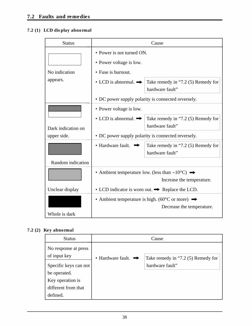
7.2 (1) LCD display abnormal
Status
No indicationappears.
Dark indication onupper side.
Random indication
Unclear display
Whole is dark
Cause
• Power is not turned ON.
• Power voltage is low.
• Fuse is burnout.
• LCD is abnormal. Take remedy in “7.2 (5) Remedy forhardware fault”
• DC power supply polarity is connected reversely.
• Power voltage is low.
• LCD is abnormal. Take remedy in “7.2 (5) Remedy forhardware fault”
• DC power supply polarity is connected reversely.
• Hardware fault. Take remedy in “7.2 (5) Remedy forhardware fault”
• Ambient temperature low. (less than -10°C)Increase the temperature.
• LCD indicator is worn out. Replace the LCD.
• Ambient temperature is high. (60°C or more)Decrease the temperature.
7.2 (2) Key abnormal
Status
No response at pressof input key
Specific keys can notbe operated.Key operation isdifferent from thatdefined.
Cause
• Hardware fault. Take remedy in “7.2 (5) Remedy forhardware fault”
39
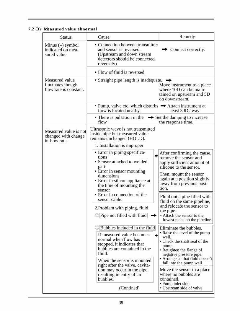
Cause
• Connection between transmitterand sensor is reversed. Connect correctly.(Upstream and down streamdetectors should be connectedreversely)
• Flow of fluid is reversed.
• Straight pipe length is inadequate.Move instrument to a placewhere 10D can be main-tained on upstream and 5Don downstream.
• Pump, valve etc. which disturbs Attach instrument atflow is located nearby. least 30D away
• There is pulsation in the Set the damping to increase flow the response time.
Ultrasonic wave is not transmittedinside pipe but measured valueremains unchanged (HOLD).
1. Installation is improper• Error in piping specifica-
tions• Sensor attached to welded
part• Error in sensor mounting
dimensions• Error in silicon appliance at
the time of mounting thesensor
• Error in connection of thesensor cable.
2.Problem with piping, fluid
Pipe not filled with fluid
Bubbles included in the fluidIf measured value becomesnormal when flow hasstopped, it indicates thatbubbles are contained in thefluid.When the sensor is mountedright after the valve, cavita-tion may occur in the pipe,resulting in entry of airbubbles.
(Contined)
Status
Minus (-) symbolindicated on mea-sured value
Measured valuefluctuates thoughflow rate is constant.
Measured value is notchanged with changein flow rate.
7.2 (3) Measured value abnormal
Remedy
After confirming the cause,remove the sensor andapply sufficient amount ofsilicone to the sensor.Then, mount the sensoragain at a position slightlyaway from previous posi-tion.
Fluid out a pipe filled withfluid on the same pipeline,and relocate the sensor tothe pipe.• Attach the sensor to the
lowest place on the pipeline.
Eliminate the bubbles.• Raise the level of the pump
well.• Check the shaft seal of the
pump.• Retighten the flange of
negative pressure pipe.• Arrange so that fluid doesn’t
fall into the pump well
Move the sensor to a placewhere no bubbles arecontained.• Pump inlet side• Upstream side of valve
40
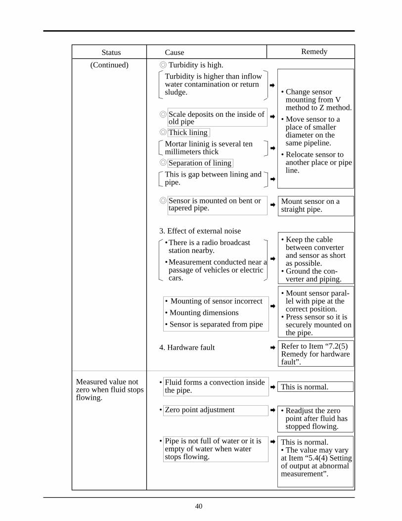
Cause
Turbidity is high.Turbidity is higher than inflowwater contamination or returnsludge.
Scale deposits on the inside ofold pipeThick lining
Mortar lininig is several tenmillimeters thickSeparation of lining
This is gap between lining andpipe.
Sensor is mounted on bent ortapered pipe.
3. Effect of external noise•There is a radio broadcaststation nearby.
•Measurement conducted near apassage of vehicles or electriccars.
• Mounting of sensor incorrect• Mounting dimensions• Sensor is separated from pipe
4. Hardware fault
• Fluid forms a convection insidethe pipe.
• Zero point adjustment
• Pipe is not full of water or it isempty of water when waterstops flowing.
Status
(Continued)
Remedy
• Change sensormounting from Vmethod to Z method.
• Move sensor to aplace of smallerdiameter on thesame pipeline.
• Relocate sensor toanother place or pipeline.
Mount sensor on astraight pipe.
• Keep the cablebetween converterand sensor as shortas possible.
• Ground the con-verter and piping.
• Mount sensor paral-lel with pipe at thecorrect position.
• Press sensor so it issecurely mounted onthe pipe.
Refer to Item “7.2(5)Remedy for hardwarefault”.
Measured value notzero when fluid stopsflowing.
This is normal.
• Readjust the zeropoint after fluid hasstopped flowing.
This is normal.• The value may varyat Item “5.4(4) Settingof output at abnormalmeasurement”.

41
Cause
• Input piping specificationsdiffer from the actual ones.
• Scale deposits on old pipe
• Length of straight pipe is inad-equate. (should be at least 10Dupstream and 5D downstream.)
• Pipe is not filled with fluid orsludge is deposited in the pipe.
Status
Error in measuredvalue
Remedy
Error of about 3%occurs when innerdiameter differs by1%.• Input the correct
specifications• Input scale as a
lining.
Change the sensor toanother mountingposition (upstream ofdisturbing objects)
No disturbing objectsin flow within 30Dupstream withoutpump, valve, com-bined pipe, etc.
• Try mounting thesensor at variousangles versus thepipe section, andmount it whereaverage value isobtained.
Occurs particularlywhere sectional areais small.• Move sensor to a vertical pipe.
42
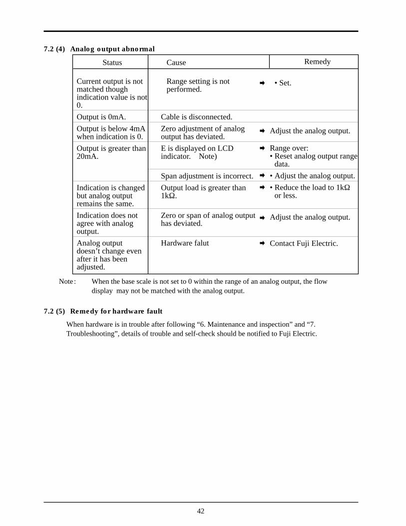
7.2 (4) Analog output abnormal
Cause
Range setting is notperformed.
Cable is disconnected.Zero adjustment of analogoutput has deviated.E is displayed on LCDindicator. Note)
Span adjustment is incorrect.Output load is greater than1kW.
Zero or span of analog outputhas deviated.
Hardware falut
Status
Current output is notmatched thoughindication value is not0.Output is 0mA.Output is below 4mAwhen indication is 0.Output is greater than20mA.
Indication is changedbut analog outputremains the same.Indication does notagree with analogoutput.Analog outputdoesn’t change evenafter it has beenadjusted.
Remedy
• Set.
Adjust the analog output.
Range over:• Reset analog output range
data.• Adjust the analog output.• Reduce the load to 1kW
or less.
Adjust the analog output.
Contact Fuji Electric.
Note : When the base scale is not set to 0 within the range of an analog output, the flowdisplay may not be matched with the analog output.
7.2 (5) Remedy for hardware fault
When hardware is in trouble after following “6. Maintenance and inspection” and “7.Troubleshooting”, details of trouble and self-check should be notified to Fuji Electric.

8. MOUNTING METHOD
8.1 Mounting of sensor8.1 (1) Mounting procedure of sensor
Mount the sensor on the pipe, and perform the following works in order before makingmeasurement.
8.1 (2) Selection of mounting place
8.1 (3) Selection of mounting method
Cable end termination
Determination ofmounting position
Processor of sensormounting surface
8.1 (4)
8.1 (5)
8.1 (6)
8.1 (7) Connection of cableto small type sensor andsensor with smalldiameter
8.1 (10) Connection of signalcable to large typesensor
8.1 (12) Mounting of hightemperature sensoron pipe
8.1 (8) Mounting of small typesensor and pipe withsmall diameter on pipe
8.1 (9) Assembly procedureof sensor
8.1 (11) Mounting of large typesensor on pipe
43
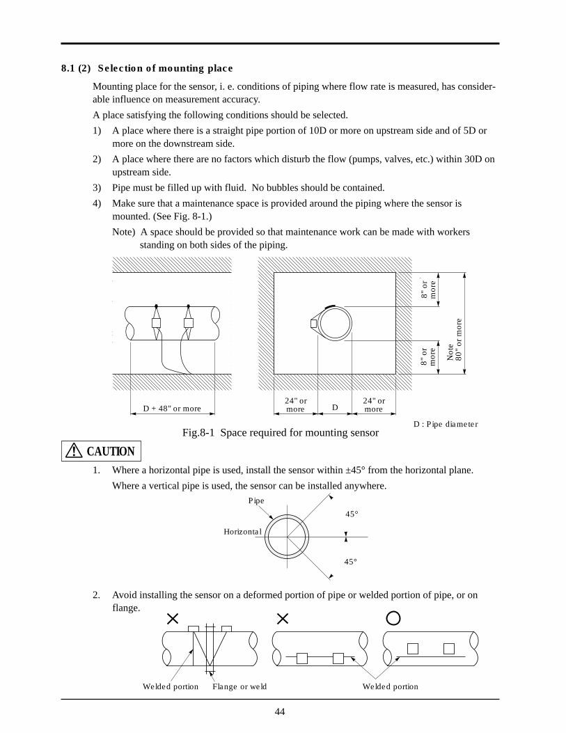
8.1 (2) Selection of mounting place
Mounting place for the sensor, i. e. conditions of piping where flow rate is measured, has consider-able influence on measurement accuracy.A place satisfying the following conditions should be selected.1) A place where there is a straight pipe portion of 10D or more on upstream side and of 5D or
more on the downstream side.2) A place where there are no factors which disturb the flow (pumps, valves, etc.) within 30D on
upstream side.3) Pipe must be filled up with fluid. No bubbles should be contained.4) Make sure that a maintenance space is provided around the piping where the sensor is
mounted. (See Fig. 8-1.)Note) A space should be provided so that maintenance work can be made with workers
standing on both sides of the piping.
Fig.8-1 Space required for mounting sensor
1. Where a horizontal pipe is used, install the sensor within ±45° from the horizontal plane.Where a vertical pipe is used, the sensor can be installed anywhere.
2. Avoid installing the sensor on a deformed portion of pipe or welded portion of pipe, or onflange.
D
200
orm
ore
200
orm
ore
Not
e2,
000
or m
ore
D : Pipe diameter
Horizontal
Pipe
45°
45°
Welded portion Flange or weld Welded portion
CAUTION
D + 48" or more24" ormore
24" ormore
8" o
rm
ore
8" o
rm
ore
Not
e80
" or
mor
e
44

Small typesensorType : FLW12
Zmethod
Zmethod
Vmethod
Vmethod
Large typesensorType : FLW51
High temperaturesensorFLW32
: Range noted in specifications: Range specified with piping material (FRP, PVC or other plastic materials)
Sensor
8.1 (3) Selection of mounting method
There are two ways for mounting the sensor, the V method and the Z method (See Fig. 8-2).
Fig. 8-2 Mounting methodThe Z method should be used in the following cases.• Where a mounting space is not available. (As shown in the figure above, the mounting dimen-
sion with the Z method is about half of that with the V method).• When measuring fluid of high turbidity such as sewage.• When the pipe has a mortar lining.• When the pipe is old and has a thick accumulation of scale on its inner wall.Selection standard
For a large size sensor with inside diameter of more than 12 in., the Z method is recom-mended for mounting.
8.1 (4) Processing of sensor mounting surface
Using thinner and/or sandpaper, remove pitch, rust and unevenness over a width of (L) + 8 in. onthe pipe circumference where the sensor is mounted.Note) If there is a jute winding on the pipe circumference, remove it and carry out the above
processing.
Sensor
D
Approx. D
V method
Sensor
D
Approx. D/2
Z method
Jute windingPipe
1" 2" 4" 8" 12" 16" 40" 120" 240"
Inside diameter (inches)
L + 8"
45
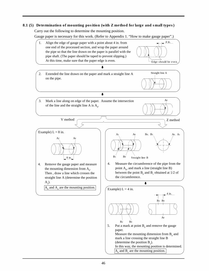
4. Measure the circumference of the pipe from thepoint A0, and mark a line (straight line B)between the point B0 and B1 obtained at 1/2 ofthe circumference.
A0A1
B1 B0 Straight line B
A0, A1B0, B1
8.1 (5) Determination of mounting position (with Z method for large and small types)Carry out the following to determine the mounting position.Gauge paper is necessary for this work. (Refer to Appendix 1. “How to make gauge paper”.)
1. Align the edge of gauge paper with a point about 4 in. fromone end of the processed section, and wrap the paper aroundthe pipe so that the line drawn on the paper is parallel with thepipe shaft. (The paper should be taped to prevent slipping.)At this time, make sure that the paper edge is even.
2. Extended the line drawn on the paper and mark a straight line Aon the pipe.
3. Mark a line along on edge of the paper. Assume the intersectionof the line and the straight line A is A0.
Edge should be even.
Straight line A
A0
Example) L = 8 in.
A0A2
Example) L = 4 in.
B0B2
B2 B0
A0
V method Z method
4 in.
4 in.
5. Put a mark at point B0 and remove the gaugepaper.Measure the mounting dimension from B0 andmark a line crossing the straight line B(determine the position B2).In this way, the mounting position is determined.A0 and B2 are the mounting position.
4. Remove the gauge paper and measurethe mounting dimension from A0.Then , draw a line which crosses thestraight line A (determine the positionA2).
A0 and A2 are the mounting position.
8 in.
46
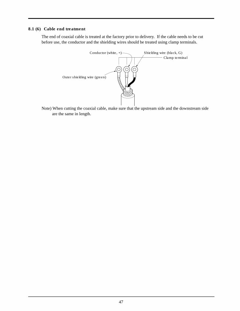
8.1 (6) Cable end treatment
The end of coaxial cable is treated at the factory prior to delivery. If the cable needs to be cutbefore use, the conductor and the shielding wires should be treated using clamp terminals.
Note) When cutting the coaxial cable, make sure that the upstream side and the downstream side are the same in length.
Outer shielding wire (green)
Clamp terminalShielding wire (black, G)Conductor (white, +)
47
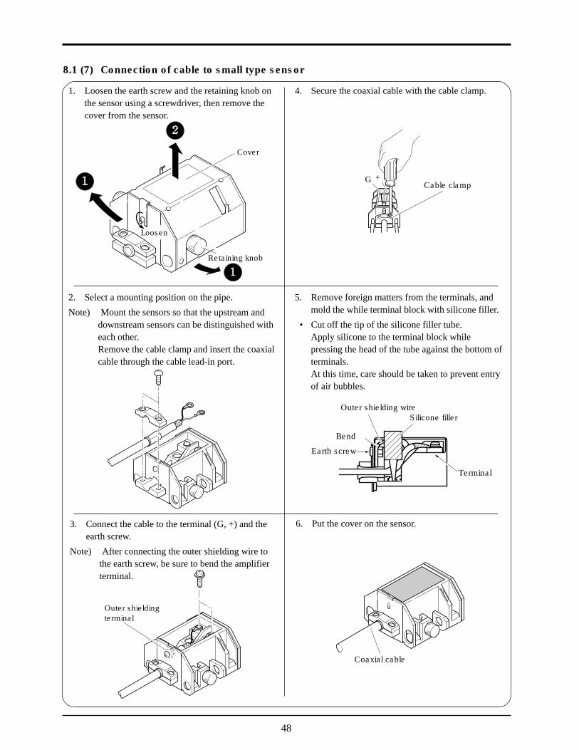
8.1 (7) Connection of cable to small type sensor
4. Secure the coaxial cable with the cable clamp.
Cable clampG +
5. Remove foreign matters from the terminals, andmold the while terminal block with silicone filler.
• Cut off the tip of the silicone filler tube.Apply silicone to the terminal block whilepressing the head of the tube against the bottom ofterminals.At this time, care should be taken to prevent entryof air bubbles.
Silicone fillerOuter shielding wire
Bend
Earth screw
Terminal
6. Put the cover on the sensor.
Coaxial cable
2. Select a mounting position on the pipe.
Note) Mount the sensors so that the upstream anddownstream sensors can be distinguished witheach other.Remove the cable clamp and insert the coaxialcable through the cable lead-in port.
3. Connect the cable to the terminal (G, +) and theearth screw.
Note) After connecting the outer shielding wire tothe earth screw, be sure to bend the amplifierterminal.
Outer shieldingterminal
1. Loosen the earth screw and the retaining knob onthe sensor using a screwdriver, then remove thecover from the sensor.
Retaining knob
Cover
Loosen
48
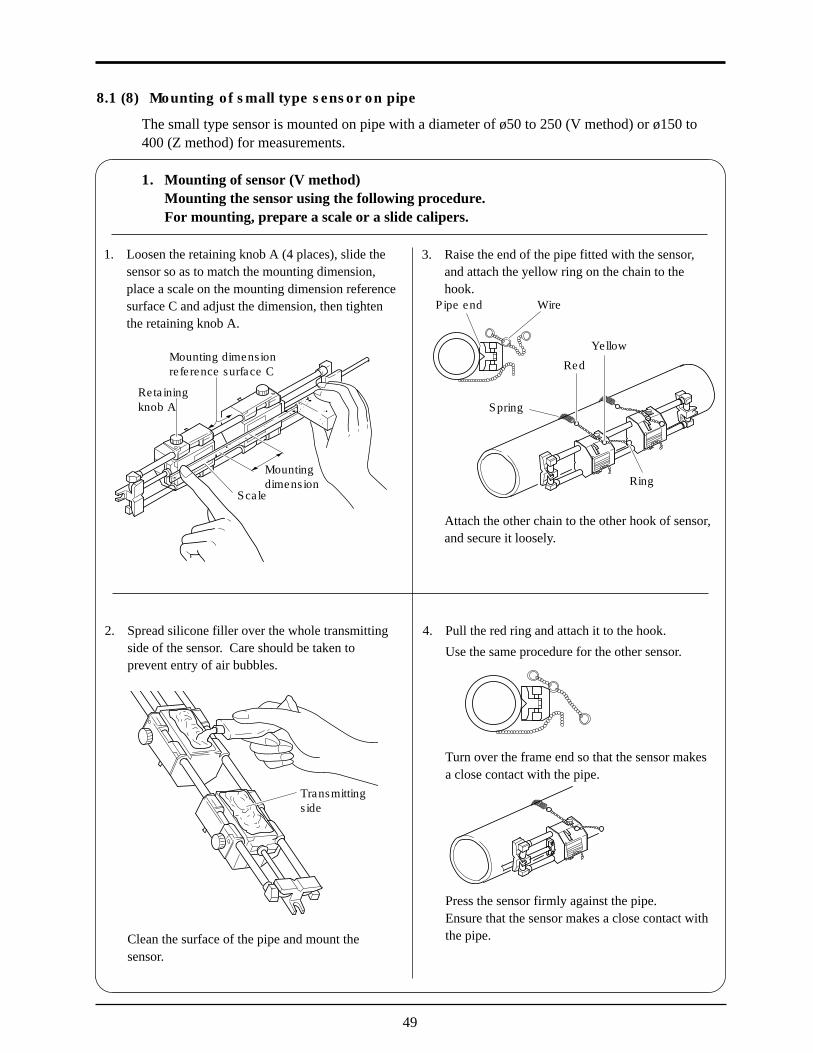
8.1 (8) Mounting of small type sensor on pipe
The small type sensor is mounted on pipe with a diameter of ø50 to 250 (V method) or ø150 to400 (Z method) for measurements.
1. Mounting of sensor (V method)Mounting the sensor using the following procedure.For mounting, prepare a scale or a slide calipers.
1. Loosen the retaining knob A (4 places), slide thesensor so as to match the mounting dimension,place a scale on the mounting dimension referencesurface C and adjust the dimension, then tightenthe retaining knob A.
Mountingdimension
Scale
Retainingknob A
Mounting dimensionreference surface C
4. Pull the red ring and attach it to the hook.
Use the same procedure for the other sensor.
Turn over the frame end so that the sensor makesa close contact with the pipe.
Press the sensor firmly against the pipe.Ensure that the sensor makes a close contact withthe pipe.
2. Spread silicone filler over the whole transmittingside of the sensor. Care should be taken toprevent entry of air bubbles.
Clean the surface of the pipe and mount thesensor.
Transmittingside
3. Raise the end of the pipe fitted with the sensor,and attach the yellow ring on the chain to thehook.
Attach the other chain to the other hook of sensor,and secure it loosely.
Red
Pipe end Wire
Ring
Spring
Yellow
49
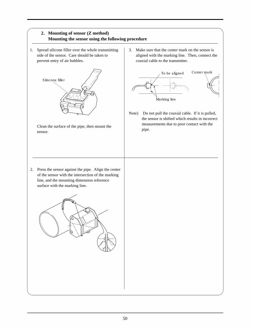
2. Mounting of sensor (Z method)Mounting the sensor using the following procedure
2. Press the sensor against the pipe. Align the centerof the sensor with the intersection of the markingline, and the mounting dimension referencesurface with the marking line.
1. Spread silicone filler over the whole transmittingside of the sensor. Care should be taken toprevent entry of air bubbles.
Clean the surface of the pipe, then mount thesensor.
Slincone filler
3. Make sure that the center mark on the sensor isaligned with the marking line. Then, connect thecoaxial cable to the transmitter.
Note) Do not pull the coaxial cable. If it is pulled,the sensor is shifted which results in incorrectmeasurements due to poor contact with thepipe.
To be aligned
Marking line
Center mark
50
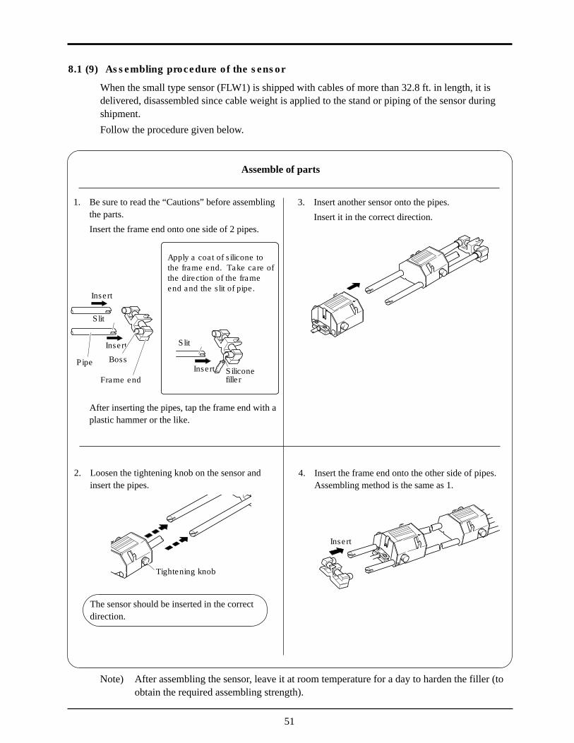
8.1 (9) Assembling procedure of the sensor
When the small type sensor (FLW1) is shipped with cables of more than 32.8 ft. in length, it isdelivered, disassembled since cable weight is applied to the stand or piping of the sensor duringshipment.Follow the procedure given below.
1. Be sure to read the “Cautions” before assemblingthe parts.
Insert the frame end onto one side of 2 pipes.
After inserting the pipes, tap the frame end with aplastic hammer or the like.
Insert
Insert Siliconefiller
Insert
Pipe Boss
Frame end
Slit
Slit
Apply a coat of silicone tothe frame end. Take care ofthe direction of the frameend and the slit of pipe.
Assemble of parts
2. Loosen the tightening knob on the sensor andinsert the pipes.
The sensor should be inserted in the correctdirection.
Tightening knob
3. Insert another sensor onto the pipes.
Insert it in the correct direction.
4. Insert the frame end onto the other side of pipes.Assembling method is the same as 1.
Insert
Note) After assembling the sensor, leave it at room temperature for a day to harden the filler (toobtain the required assembling strength).
51
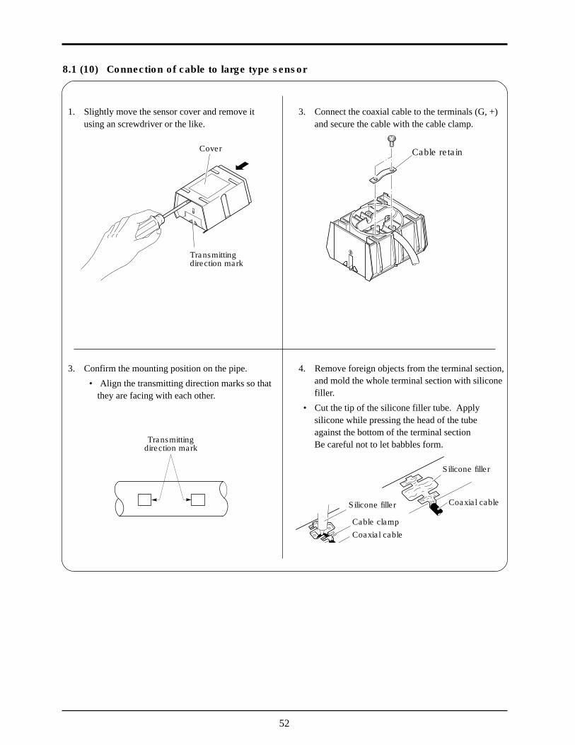
8.1 (10) Connection of cable to large type sensor
1. Slightly move the sensor cover and remove itusing an screwdriver or the like.
3. Confirm the mounting position on the pipe.
• Align the transmitting direction marks so thatthey are facing with each other.
Transmittingdirection mark
3. Connect the coaxial cable to the terminals (G, +)and secure the cable with the cable clamp.
Cable retain
4. Remove foreign objects from the terminal section,and mold the whole terminal section with siliconefiller.
• Cut the tip of the silicone filler tube. Applysilicone while pressing the head of the tubeagainst the bottom of the terminal sectionBe careful not to let babbles form.
Silicone filler
Coaxial cableSilicone filler
Cable clampCoaxial cable
Cover
Transmittingdirection mark
52
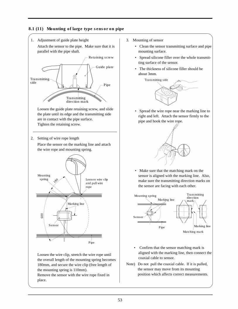
8.1 (11) Mounting of large type sensor on pipe
1. Adjustment of guide plate height
Attach the sensor to the pipe. Make sure that it isparallel with the pipe shaft.
Loosen the guide plate retaining screw, and slidethe plate until its edge and the transmitting sideare in contact with the pipe surface.Tighten the retaining screw.
2. Setting of wire rope length
Place the sensor on the marking line and attachthe wire rope and mounting spring.
Loosen the wire clip, stretch the wire rope untilthe overall length of the mounting spring becomes180mm, and secure the wire clip (free length ofthe mounting spring is 110mm).Remove the sensor with the wire rope fixed inplace.
3. Mounting of sensor
• Clean the sensor transmitting surface and pipemounting surface.
• Spread silicone filler over the whole transmit-ting surface of the sensor.
• The thickness of silicone filler should beabout 3mm.
• Spread the wire rope near the marking line toright and left. Attach the sensor firmly to thepipe and hook the wire rope.
• Make sure that the matching mark on thesensor is aligned with the marking line. Also,make sure the transmitting direction marks onthe sensor are facing with each other.
• Confirm that the sensor matching mark isaligned with the marking line, then connect thecoaxial cable to sensor.
Note) Do not pull the coaxial cable. If it is pulled,the sensor may move from its mountingposition which affects correct measurements.
Pipe
Guide plate
Retaining screw
Transmittingside
Transmittingdirection mark
180
600
Sensor
Marking line
Mountingspring Loosen wire clip
and pull wirerope
Pipe
Transmitting side
Transmittingdirectionmark
Matching mark
Marking line
Sensor
Marking lineMounting spring
Pipe
53

8.1 (12) Mounting of high temperature sensor on pipe
2. Spread high-temperature grease over the wholetransmitting surface of the sensor.
Turn the element holder counterclockwise toreturn the sensor. Clean the surface of the pipeand mount the sensor on the pipe.
Transmitting surface
Element holder
High -temperaturegrease
3. Mount the sensor saddles on the pipe with stain-less belt.
Stainless belt
1. By loosening lock nuts, slide the sensor to fit themounting size displayed on the converter.Tighten the lock nuts.
BN connector
Elementholder
Locking nut
Saddle
Cursor
Frame
Scale
Mountingdimension (L)
4. Check that the sensor is properly attached inparallel to the pipe and it is mounted according tothe mounting dimension. Then, turn the elementholder clockwise, so that the sensor makes a closecontact with the pipe.
Stop turning the element holder where the trans-mitting surface contact the surface of pipe, andthus the element holder won’t rotate. Don’t turnit excessively.
Element holder
Cable
54
A-1
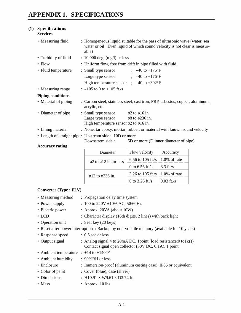
APPENDIX 1. SPECIFICATIONS
(1) SpecificationsServices
• Measuring fluid : Homogeneous liquid suitable for the pass of ultrasonic wave (water, seawater or oil Even liquid of which sound velocity is not clear is measur-able)
• Turbidity of fluid : 10,000 deg. (mg/l) or less• Flow : Uniform flow, free from drift in pipe filled with fluid.• Fluid temperature : Small type sensor ; -40 to +176°F
Large type sensor ; -40 to +176°FHigh temperature sensor ; -40 to +392°F
• Measuring range : -105 to 0 to +105 ft./sPiping conditions• Material of piping : Carbon steel, stainless steel, cast iron, FRP, asbestos, copper, aluminum,
acrylic, etc.• Diameter of pipe : Small type sensor ø2 to ø16 in.
Large type sensor ø8 to ø236 in.High temperature sensor ø2 to ø16 in.
• Lining material : None, tar epoxy, mortar, rubber, or material with known sound velocity• Length of straight pipe : Upstream side : 10D or more
Downstrem side : 5D or more (D:inner diameter of pipe)Accuracy rating
Converter (Type : FLV)
• Measuring method : Propagation delay time system• Power supply : 100 to 240V ±10% AC, 50/60Hz• Electric power : Approx. 20VA (about 10W)• LCD : Character display (16th digits, 2 lines) with back light• Operation unit : Seat key (20 keys)• Reset after power interruption : Backup by non-volatile memory (available for 10 years)• Response speed : 0.5 sec or less• Output signal : Analog signal 4 to 20mA DC, 1point (load resistance:0 to1kW)
Contact signal open collector (30V DC, 0.1A), 1 point• Ambient temperature : +14 to +140°F• Ambient humidity : 90%RH or less• Enclosure : Immersion-proof (aluminum casting case), IP65 or equivalent• Color of paint : Cover (blue), case (silver)• Dimensions : H10.91 ´ W9.61 ´ D3.74 ft.• Mass : Approx. 10 lbs.
Flow velocity Accuracy
6.56 to 105 ft./s 1.0% of rate
0 to 6.56 ft./s 3.3 ft./s
3.26 to 105 ft./s 1.0% of rate
0 to 3.26 ft./s 0.03 ft./s
Diameter
ø2 to ø12 in. or less
ø12 to ø236 in.

A-2
Sensor (Type : FLW)
• Mounting method : Pipe-mounting• Mounting method of sensor: V method or Z method• Attaching belt/wire : Small type sensor: stainless chain
Large type sensor: stainless wireHigh temperature sensor: stainless belt
• Sound coupler : Silicon rubber• Signal cable : Dedicated coaxial cable (standard 16 ft., max.492 ft.)• Connection : Terminal screw
High temperature sensor: BNC connector• Ambient temperature : -4 to +140°F• Ambient humidity : 100%RH or less• Enclosure : Immersion-proof type (IP67 or equivalent)
High temperature sensor: Drip-proof type (IP52 or equivalent)• Material :• Dimensions and mass : Types Sensor case Guide rail
Small type sensor Plastic SUS304 + plasticLarge type sensor Plastic ——————High temperature sensor SUS304 Aluminum alloy + SUS304
Types Dimensions (H ´ W ´ D) MassSmall type sensor 1.67 ´ 2.62 ´ 1.31 ft. Approx. 2.2 lbs.Large type sensor .34 ´ .3 ´ .2 ft. Approx. 3.1 lbs.High temperature sensor 1.74 ´ .17 ´ .67 ft. Approx. 3.6 lbs.
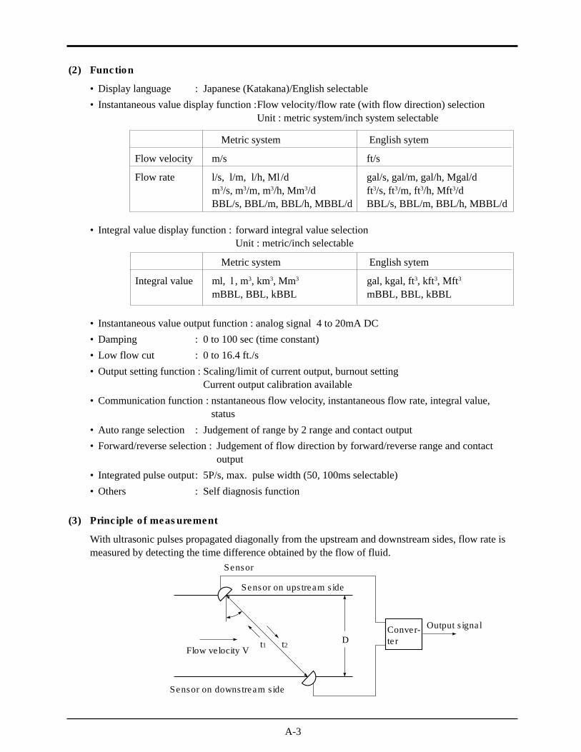
A-3
(2) Function
• Display language : Japanese (Katakana)/English selectable• Instantaneous value display function :Flow velocity/flow rate (with flow direction) selection
Unit : metric system/inch system selectable
• Integral value display function : forward integral value selectionUnit : metric/inch selectable
• Instantaneous value output function : analog signal 4 to 20mA DC• Damping : 0 to 100 sec (time constant)• Low flow cut : 0 to 16.4 ft./s• Output setting function : Scaling/limit of current output, burnout setting
Current output calibration available• Communication function : nstantaneous flow velocity, instantaneous flow rate, integral value,
status• Auto range selection : Judgement of range by 2 range and contact output• Forward/reverse selection : Judgement of flow direction by forward/reverse range and contact
output• Integrated pulse output: 5P/s, max. pulse width (50, 100ms selectable)• Others : Self diagnosis function
(3) Principle of measurement
With ultrasonic pulses propagated diagonally from the upstream and downstream sides, flow rate ismeasured by detecting the time difference obtained by the flow of fluid.
Metric system English sytem
Flow velocity m/s ft/s
Flow rate l/s, l/m, l/h, Ml/d gal/s, gal/m, gal/h, Mgal/dm3/s, m3/m, m3/h, Mm3/d ft3/s, ft3/m, ft3/h, Mft3/dBBL/s, BBL/m, BBL/h, MBBL/d BBL/s, BBL/m, BBL/h, MBBL/d
Metric system English sytem
Integral value ml, l , m3, km3, Mm3 gal, kgal, ft3, kft3, Mft3
mBBL, BBL, kBBL mBBL, BBL, kBBL
t1 t2
Sensor
Sensor on upstream side
Flow velocity V
Sensor on downstream side
Conver-ter
Output signal
D
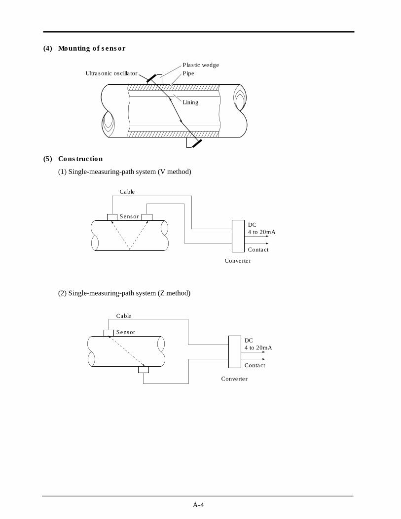
A-4
(4) Mounting of sensor
(5) Construction
(1) Single-measuring-path system (V method)
(2) Single-measuring-path system (Z method)
Ultrasonic oscillator PipePlastic wedge
Lining
Sensor
Cable
Converter
Contact
DC4 to 20mA
Contact
Sensor
Cable
DC4 to 20mA
Converter
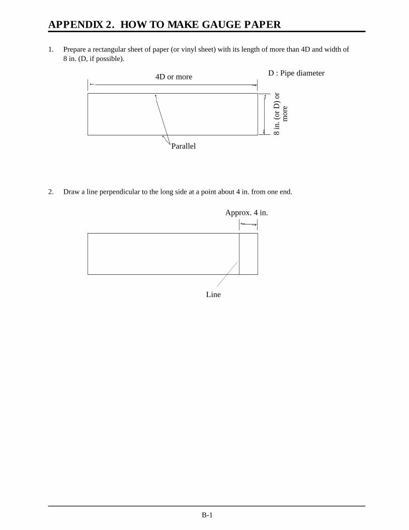
APPENDIX 2. HOW TO MAKE GAUGE PAPER
1. Prepare a rectangular sheet of paper (or vinyl sheet) with its length of more than 4D and width of8 in. (D, if possible).
®®
®
®
4D or more
8 in
. (or
D) o
rm
ore
®
®
Parallel
D : Pipe diameter
2. Draw a line perpendicular to the long side at a point about 4 in. from one end.
Approx. 4 in.®®
Line
B-1

C-1
(1) SETTING OF MEASURE DISPLAY
APPENDIX 3. COMPOSITION OF KEY OPERATION
VELOCITY
[Initial value]
RANGE %[Velocity]
TOTAL FORWARDTOTAL REVERSETOTAL DIFF.F : TOTAL PULSER : TOTAL PULSE
gal/sgal/m
[m3/s][ft3/s]
gal/hMgal/dft3/sft3/mft3/hMft3/dBBL/sBBL/mBBL/hMBBL/d
l/sl/ml/hMl/dm3/sm3/mm3/hMm3/dBBL/sBBL/mBBL/hMBBL/d(METRIC) (ENGLISH)
00000000. [00000.000]0000000.0000000.0000000.0000000.0000000.0000000.0000000.0000000
1 : DISPLAY KIND
2 : FLOW UNIT
3 : DECIMAL POINT
FUNC DISP
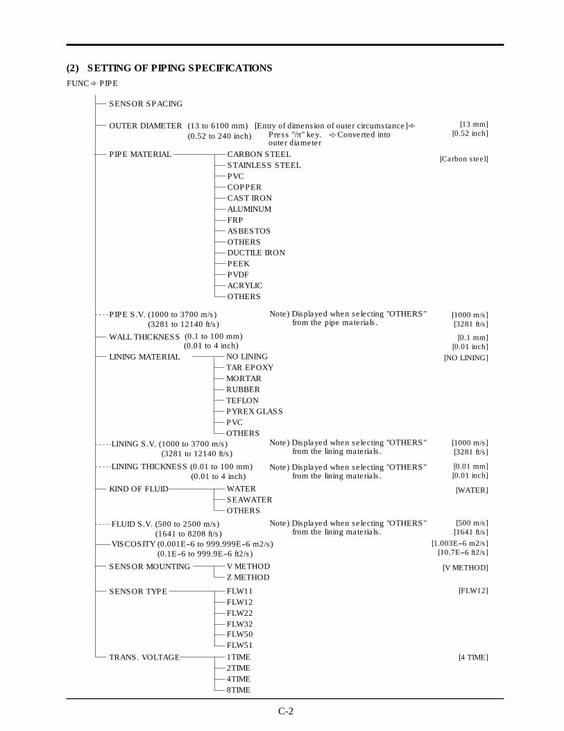
C-2
(2) SETTING OF PIPING SPECIFICATIONS
SENSOR SPACING
OUTER DIAMETER
PIPE MATERIAL
PIPE S.V. (1000 to 3700 m/s)
WALL THICKNESS
LINING MATERIAL
(13 to 6100 mm) [Entry of dimension of outer circumstance]
(0.1 to 100 mm)
(0.52 to 240 inch)
FUNC PIPE
CARBON STEELSTAINLESS STEELPVCCOPPERCAST IRONALUMINUMFRPASBESTOSOTHERSDUCTILE IRONPEEKPVDFACRYLICOTHERS
NO LINING
KIND OF FLUID WATER
SENSOR MOUNTING V METHODZ METHOD
SENSOR TYPE FLW11FLW12FLW22FLW32
TRANS. VOLTAGE 1TIME2TIME4TIME8TIME
FLW50FLW51
SEAWATEROTHERS
TAR EPOXYMORTARRUBBERTEFLONPYREX GLASSPVCOTHERS
(3281 to 12140 ft/s)
(0.01 to 4 inch)
LINING S.V. (1000 to 3700 m/s)(3281 to 12140 ft/s)
LINING THICKNESS (0.01 to 100 mm)(0.01 to 4 inch)
FLUID S.V. (500 to 2500 m/s)(1641 to 8208 ft/s)
VISCOSITY (0.001E-6 to 999.999E-6 m2/s)(0.1E-6 to 999.9E-6 ft2/s)
Note) Displayed when selecting "OTHERS" from the pipe materials.
Note) Displayed when selecting "OTHERS" from the lining materials.
Press "/p" key. Converted intoouter diameter
[13 mm][0.52 inch]
[1000 m/s][3281 ft/s]
[1000 m/s][3281 ft/s]
[500 m/s][1641 ft/s]
[0.1 mm][0.01 inch]
[NO LINING]
[0.01 mm][0.01 inch]
[WATER]
[Carbon steel]
[10.7E-6 ft2/s][1.003E-6 m2/s]
Note) Displayed when selecting "OTHERS" from the lining materials.
Note) Displayed when selecting "OTHERS" from the lining materials.
[V METHOD]
[4 TIME]
[FLW12]

C-3
(3) SETTING OF FLOW SWITCH
FLOW SW LOW (0 to ±32 m/s)
(0 to ±32 m/s)(0 to ±105 ft/s)
(0 to ±105 ft/s)
FLOW SW HIGH
(0 to 20%)FLOW SW HYS.
FUNC FLOW SW
[0 m/s][0 ft/s]
[32 m/s][105 ft/s]
[10 %]
(5) SETTING OF DAMPING
(4) SETTING OF OUTPUT
RANGE UNIT
RANGE TYPE
m/sl/sl/ml/hMl/dm3/sm3/mm3/hMm3/dBBL/sBBL/mBBL/hMBBL/d
(METRIC) (ENGLISH)ft/sgal/sgal/mgal/hMgal/dft3/sft3/mft3/hMft3/dBBL/sBBL/mBBL/hMBBL/d
SINGLE RANGE
OUTPUT LIMIT LOW (–20 to 120 %)
OUTPUT BURNOUT
BURNOUT TIMER (0 to 900 sec)
OUTPUT LIMIT HIGH (–20 to 120 %)
BASE SCALE (0 to ±32 m/s)(0 to ±105 ft/s)
FULL SCALE (±0.3 to ±32 m/s)(±1 to ±105 ft/s)
AUTO 2 RANGESBASE SCALE (0 to ±32 m/s)
(0 to ±105 ft/s)
(0 to 20%)
FULL SCALE1
FULL SCALE 2
(±0.3 to ±32 m/s)(±1 to ±105 ft/s)(±0.3 to ±32 m/s)(±1 to ±105 ft/s)
RANGE HYSTERESIS
BI-DIR. RANGE
Same as AUTO 2 RANGES
NOT USEDHOLDUPPERLOWERZERO
[m/s][ft/s]
[0 m/s][0 ft/s]
[32 m/s][105 ft/s]
[0 m/s][0 ft/s]
[32 m/s][105 ft/s][32 m/s]
[105 ft/s]
[10 %]
[–20 %]
[120 %]
[NOT USED]
[0 sec]
[SINGLE RANGE]
FUNC DAMP
DAMPING (0 to 100 sec) [5 sec]
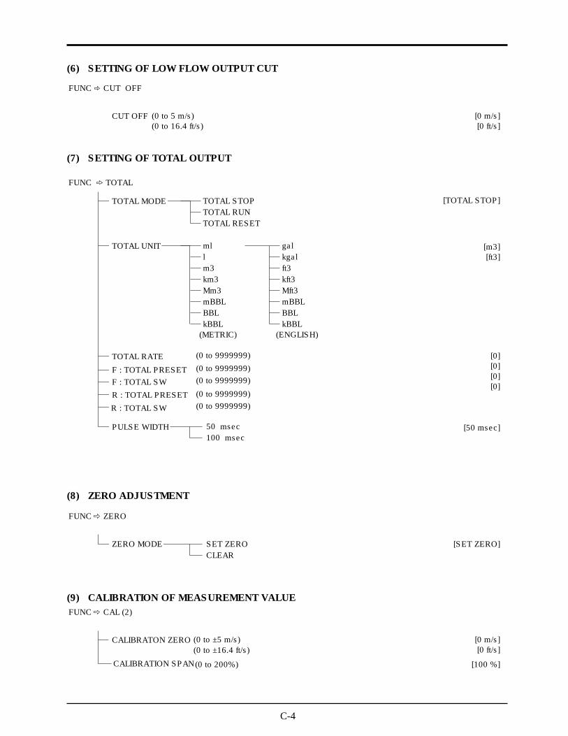
C-4
(6) SETTING OF LOW FLOW OUTPUT CUT
(7) SETTING OF TOTAL OUTPUT
(8) ZERO ADJUSTMENT
(9) CALIBRATION OF MEASUREMENT VALUE
CUT OFF (0 to 5 m/s)(0 to 16.4 ft/s)
[0 m/s][0 ft/s]
FUNC CUT OFF
[m3][ft3]
[TOTAL STOP]TOTAL MODE
FUNC TOTAL
TOTAL STOPTOTAL RUN
TOTAL UNIT
TOTAL RATE
F : TOTAL PRESETF : TOTAL SW
(0 to 9999999)(0 to 9999999)(0 to 9999999)
(0 to 9999999)(0 to 9999999)
50 msec100 msec
R : TOTAL PRESET
PULSE WIDTH
mllm3km3Mm3mBBLBBLkBBL
(METRIC)
galkgalft3kft3Mft3mBBLBBLkBBL
(ENGLISH)
TOTAL RESET
R : TOTAL SW
[0][0][0][0]
[50 msec]
ZERO MODE
FUNC ZERO
SET ZEROCLEAR
[SET ZERO]
[0 m/s][0 ft/s]
[100 %]
CALIBRATON ZERO (0 to ±5 m/s)
(0 to 200%)
(0 to ±16.4 ft/s)
CALIBRATION SPAN
FUNC CAL (2)

C-5
(10) SETTING OF SYSTEM CONDITION
SYSTEM OF UNIT
FUNC SYSTEM
METRIC [METRIC]
[ENGLISH]
[4mA]
[0 %]
[OFF]
ENGLISH
LANGUAGE
OUTPUT CHECK (-20 to 120 %)
ENGLISHJAPANESE
OUTPUT ADJUST SKIPSETTING 4 mA
20 mASTATUS CHECK CHANNEL 1
CHANNEL 2
OFFON
TEST MODE NOT USED
SETTING INPUT DATA (0 to ±120 %)TRACKING TIME (0 to 900 sec)
OFFON
[OFF]
[NOT USED]
[0 %][0 sec]

C-6
(11) SELECTING OF STATUS
STATUS CHANNEL
STATUS INF. (only display) Note) STATUS OFF ®0STATUS ON ®1
SIGNAL ERRORF : TOTAL PULSER : TOTAL PULSEFLOW SW HIGHFLOW SW LOWF : TOTAL ALARMR : TOTAL ALARMF : TOTAL OVERFLOWR : TOTAL OVERFLOWFULL SCALE2FLOW DIRECTIONRANGE OVERreservereservereserveBACKUP ERROR
FUNC STATUS
CHANNEL 1
CHANNEL 2
STATUS SEL.:CH1
STATUS MODE:CH1
same as CHANNEL 1
NOT USED
NORMALREVERSE
SIGNAL ERRORF : TOTAL PULSER : TOTAL PULSE
FLOW SW LOWFLOW SW HIGH
F : TOTAL ALARMR : TOTAL ALARMF : TOTAL OVERFLOWR : TOTAL OVERFLOWFULL SCALE2R : FLOW DIRECTIONRANGE OVERBACKUP ERROR
[NOT USED]
[NORMAL]

C-7
(12) ERROR CHECK
R : NORMAL
C : CAL. ERROR CHECK PIPE DATA
POWER OFF®ON
FUNC CHECK
I : NO RECEIVED SIGNAL
CHECK PIPE DATA
CHECK SENSOR MOUNT
CHECK CABLE CONNECT
CHECK SENSOR TYPE
H : RECEIVED SIGNAL ERROR
CHECK BUBBLES IN PIPE
W : WINDOW ERROR CHECK PIPE DATA
O : RECEIVED SIGNAL OVERFLOW
CHANGE MOUNTING METHOD
CHECK PARTICLES IN PIPE
E : RANGE OVER CHECK OUTPUT RANGE
B : BACKUP ERROR EEPROM FAULT
S : WINDOW SCANNING PLEASE WAIT NOW
T : TEST MODE TEST MODE RUNNING
CHECK TOTAL RATE

D-1
APPENDIX 4. PIPING DATA
Stainless steel pipe for pipe arrangement (JIS G3459-1988)
Nominaldiameter
(in.)Outer
diameter(in.)
Normal thicknessSchedule
5SSchedule
10SSchedule
20SSchedule
40Schedule
80Schedule
120Schedule
160Thickness
(in.)Thickness
(in.)Thickness
(in.)Thickness
(in.)Thickness
(in.)Thickness
(in.)Thickness
(in.)A B
1.0 1.3 .06 .11 .12 .13 .18 .251.3 1.7 .06 .11 .12 .14 .19 .251.6 1.9 .06 .11 .12 .15 .20 .282.0 2.4 .06 .11 .14 .15 .22 .342.6 3.0 .08 .12 .14 .20 .28 .373.1 3.5 .08 .12 .16 .22 .30 .443.5 4.0 .08 .12 .16 .22 .32 .504.0 4.5 .08 .12 .16 .24 .34 .534.9 5.5 .11 .13 .20 .26 .37 .635.9 6.5 .11 .13 .20 .28 .43 .728.0 8.5 .11 .16 .26 .32 .50 .91
10.0 .39 10.5 .13 .16 .26 .37 .59 1.1312.0 .47 12.5 .16 .18 .26 .41 .69 1.3113.8 .55 14.0 — .44 .75 1.4115.7 .63 16.0 — .50 .84 1.59
19.7 .79 20.0 — .59 1.03 1.97
.44
.50
.56
.72
.841.001.091.22
17.7 .70 18.0 — .56 .94 1.781.371.50
.6 .9 .06 .08 .10 .11 .15 .22
.8 1.1 .06 .08 .10 .11 .15 .22
21.7 .87 22.0 — .63 1.13 2.131.6323.6 .94 24.0 — .69 1.34 2.341.8125.6 1.02 26.0 —
——
——
———
——
——
———
——
——
——
———
.74 1.34 2.531.93
Polyethylene pipe for city water (JIS K6762-1982)
Galvanized steel pipe for city water SGPW (JIS G3442-1988)
Outerdiameter
(in.)Thickness
(in.)Weight(lb./ft.)
1.0 1.34 .20 3.06 .14 2.331.2 1.65 .22 4.24 .16 3.311.6 1.89 .26 5.70 .18 4.272.0 2.36 .31 8.75 .20 6.00
Nominaldiameter
(in.)
1st type (Soft pipe)
Thickness(in.)
Weight(lb./ft.)
2nd type (Hard pipe)
.8 1.06 .16 1.95 .12 1.57
.5 .85 .14 1.33 .10 1.03
Outer diameter(in.)
Thickness(in.)
1.0 .131.3 .141.6 .142.0 .15
Nominal pipe
2.63.13.54.04.95.98.0
10.012.0
.17
.17
.17
.18
.18
.20
.23
.26
.27
(B)(A)
.8 .11
.6 .11
.16
.20
.24
.32
.08
.10
.12
.14
.03
.04
.05
.06
.02
.39
.47
.16
.20
.24
.32
.08
.10
.12
.14
.03
.04
.05
.06
.02
1.31.71.92.43.03.54.04.55.56.58.5
10.512.5
.91.1
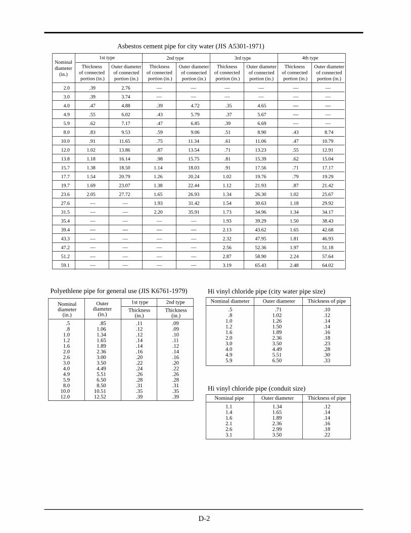
D-2
Asbestos cement pipe for city water (JIS A5301-1971)
Polyethlene pipe for general use (JIS K6761-1979) Hi vinyl chloride pipe (city water pipe size)
Hi vinyl chloride pipe (conduit size)Outer diameter Thickness of pipe
1.1 1.34 .121.4 1.65 .141.6 1.89 .142.1 2.36 .16
Nominal pipe
2.63.1
2.993.50
.18
.22
Outer diameter Thickness of pipe
1.0 1.26 .141.2 1.50 .141.6 1.89 .162.0 2.36 .18
Nominal diameter
3.04.04.95.9
3.504.495.516.50
.23
.28
.30
.33
.8 1.02 .12
.5 .71 .10Outer
diameter(in.)
Thickness(in.)
1.0 1.34 .12 .101.2 1.65 .14 .111.6 1.89 .14 .122.0 2.36 .16 .14
Nominaldiameter
(in.)
1st type
2.6 3.00 .20 .163.0 3.50 .22 .204.0 4.49 .24 .224.9 5.51 .26 .265.9 6.50 .28 .288.0 8.50 .31 .31
10.0 10.51 .35 .3512.0 12.52 .39 .39
.8 1.06 .12 .09
.5 .85 .11 .09
2nd typeThickness
(in.)
Nominaldiameter
(in.)Outer diameterof connectedportion (in.)
1st type
Thicknessof connectedportion (in.)
2.0 .39 2.76 — —
.35 4.65
—
8.74
3.0 .39 3.74 — —
.37 5.67
—
10.79
4.0 .47 4.88 .39 4.72
.39 6.69
—
12.91
4.9 .55 6.02 .43 5.79
.51 8.90
—
15.04
5.9 .62 7.17 .47 6.85
.61 11.06
—
17.17
8.0 .83 9.53 .59 9.06
.81
13.23
19.29
10.0 .91 11.65 .75 11.34
.91
15.39
21.42
12.0 1.02 13.86 .87 13.54
1.02
17.56
25.67
13.8 1.18 16.14 .98 15.75
1.12
19.76
29.92
15.7 1.38 18.50 1.14 18.03
1.34
21.93
34.17
17.7 1.54 20.79 1.26 20.24
1.54
26.30
38.43
19.7 1.69 23.07 1.38 22.44
1.73
30.63
42.68
23.6 2.05 27.72 1.65 26.93
1.93
34.96
46.93
27.6
2.13
39.29
51.18
31.5
2.32
43.62
57.64
35.4
2.56
47.95
64.02
39.4
2.87
52.36
1.93
2.20
31.42
35.91
—
—
.55
.62
.71
.79
.87
1.02
1.18
1.34
1.50
1.65
Outer diameterof connectedportion (in.)
2nd type
Thicknessof connectedportion (in.)
Outer diameterof connectedportion (in.)
3rd type
Thicknessof connectedportion (in.)
Outer diameterof connectedportion (in.)
4th type
Thicknessof connectedportion (in.)
43.3
47.2
51.2
59.1
—
—
—
—
.71
3.19
—
—
—
—
—
—
—
—
—
—
—
—
—
—
—
—
—
—
—
—
—
—
—
—
—
—
58.90
65.43
.47
.43
1.81
1.97
2.24
2.48
—
—
—
—
—
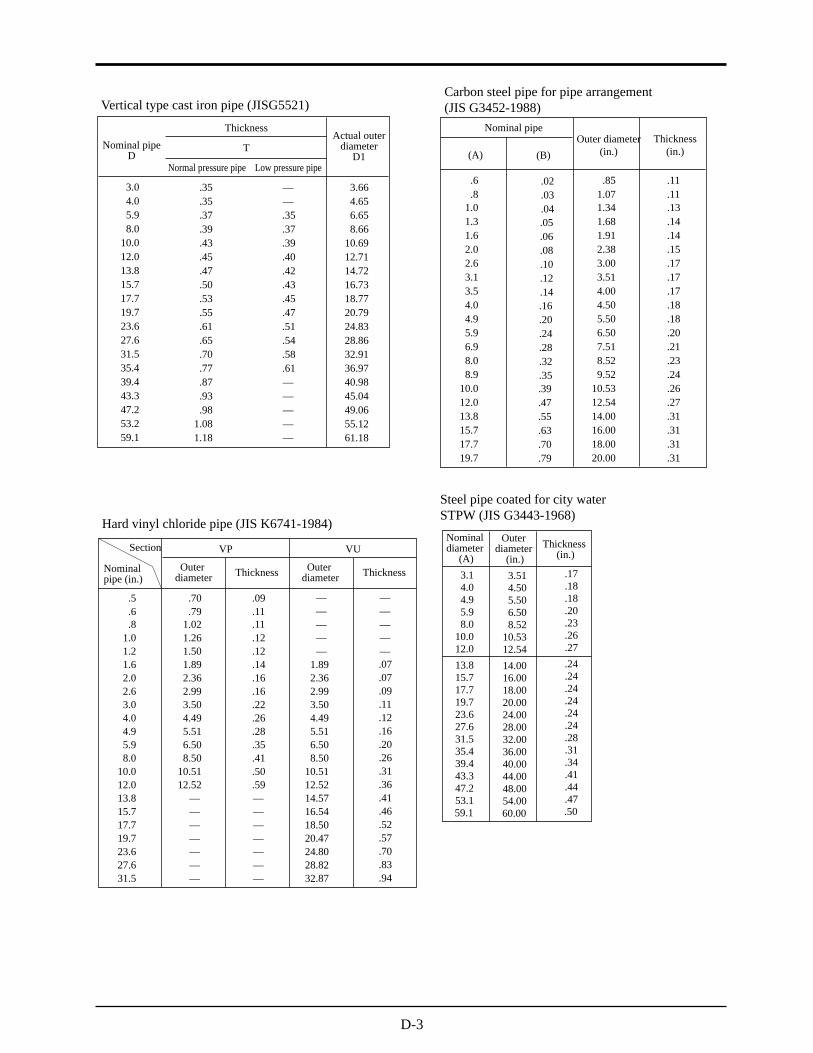
D-3
Vertical type cast iron pipe (JISG5521)
.35 3.663.0
.35 4.654.0
.37 6.65
.39 8.665.9
.43 10.698.0
.45 12.7110.0
.47 14.7212.0
.50 16.7313.8
.53 18.7715.7
.55 20.7917.7
.61 24.8319.7
.65 28.8623.6
.70 32.9127.6
.77 36.9731.5
.87 40.9835.4
.93 45.0439.4
.98
.35
.37
.39
.40
.42
.43
.45
.47
.51
.54
Nominal pipeD
ThicknessActual outer
diameterD1
43.347.253.259.1
1.081.18
——
.58
.61——
T
Normal pressure pipe Low pressure pipe
———
49.0655.1261.18
Hard vinyl chloride pipe (JIS K6741-1984)
Carbon steel pipe for pipe arrangement(JIS G3452-1988)
Thickness
1.0 1.26 .121.2 1.50 .121.6 1.89 .14 1.89 .072.0 2.36 .16 2.36 .07
Nominalpipe (in.)
VP VUSection
Outerdiameter
Outerdiameter Thickness
2.6 2.99 .16 2.99 .093.0 3.50 .22 3.50 .114.0 4.49 .26 4.49 .124.9 5.51 .28 5.51 .165.9 6.50 .35 6.50 .208.0 8.50 .41 8.50 .26
10.0 10.51 .50 10.51 .3112.0 12.52 .59 12.52 .3613.8 — 14.57 .4115.7 — 16.54 .4617.7 — 18.50 .5219.7 — 20.47 .5723.6 — 24.80 .7027.6 — 28.82 .8331.5 —
———————
—————
—————
32.87 .94
.6 .79 .11
.5 .70 .09
.8 1.02 .11
.39
.47
Outer diameter(in.)
Thickness(in.)
1.0 1.34 .131.3 1.68 .141.6 1.91 .142.0 2.38 .15
Nominal pipe
2.63.13.54.04.95.9
8.0
10.012.0
3.003.514.004.505.506.50
8.52
10.5312.54
.17
.17
.17
.18
.18
.20
.23
.26
.27
(B)(A)
6.9 7.51 .21
8.9 9.52 .24
.5513.8 14.00 .31
.6315.7 16.00 .31
.7017.7 18.00 .31
.7919.7 20.00 .31
.8 1.07 .11
.6 .85 .11
Steel pipe coated for city waterSTPW (JIS G3443-1968)
Outerdiameter
(in.)Thickness
(in.)
3.1 3.51 .174.0 4.50 .184.9 5.50 .185.9 6.50 .20
Nominaldiameter
(A)
8.0 8.52 .2310.0 10.53 .2612.0 12.54 .27
13.8 14.00 .2415.7 16.00 .2417.7 18.00 .2419.7 20.00 .2423.6 24.00 .2427.6 28.00 .2431.5 32.00 .2835.4 36.00 .3139.4 40.00 .3443.3 44.00 .4147.2 48.00 .4453.1 54.00 .4759.1 60.00 .50
.16
.20
.24
.28
.32
.35
.05
.06
.08
.10
.12
.14
.02
.03
.04

D-4
Steel pipe coated for city water STW (JIS G3443 1987)
Centrifugal nodular graphite cast iron pipe for city water (A type) (JWWA G-105 1971)
.30 3.663.0
.30 4.654.0
.37 6.65
.30 8.665.9
.30 10.698.0
.30 12.7110.0
.30 14.7212.0
.33 16.7313.8
.35 18.7715.7
.37 20.7917.719.7
.30
.31
.33
Nominal diameter Thickness of pipe Actual outer diameter
——
T1st type pipe 2nd type pipe
.24
.24
.24
.24
.24
.26
.26
.28
.30
.28
3rd type pipeD D1
—————
Nominaldiameter
A
Outerdiameter
in.
Kinds of symbol
STW 30 STW 38
STW 41
Thickness(in.)
Thickness(in.)
Thickness(in.)
Thickness(in.)
5.9 6.50 .20 .228.0 8.52 .23 .25
10.0 10.53 .26 .2512.0 12.54 .27 .2513.8 14.00 .2415.7 16.00 .2417.7 18.00 .2419.7 20.00 .2423.6 24.00 .2427.6 28.00 — .28 .2431.5 32.00 — .31 .2835.4 36.00 — .31 .2839.4 40.00 — .35 .31
4.9 5.50 .18 .204.0 4.50 .18 .19
A BNominal thickness STW 290 STW 370
STW 400
Thickness(in.)
Thickness(in.)
Thickness(in.)
Thickness(in.)
3.1 3.51 .17 .18
A BNominal thickness
53.2 54.00 .47 .3959.1 60.00 .55 .4363.0 63.98 .59 .4765.0 66.00 .59 .4770.9 72.00 .63 .5174.8 76.00 .67 .5578.7 80.00 .71 .5982.7 84.00 .75 .63
90.6 92.00 — .83 .6794.5 96.00 — .87 .7198.4 100.00 — .91 .71
102.4 104.00 — .94 .75
47.2 48.00 .43 .3543.3 44.00 .39 .31
86.6 88.00 .79 .63
106.3 108.00 — .98 .79110.2 112.00 — 1.02 .83114.2 116.00 — 1.06 .83118.1 120.00 — 1.14 .87
—————
———————————
————
————————
—————
—————
————
———
————
———
—————
————
———
————
———
———————————
————
————————
—————
———————————
————
————————
—————
———————————
Kinds of symbol
.20
.23
.26
.27
.18
.18
.17
.22
.25
.25
.25
.20
.19
.18
.24
.24
.24
.24
.24
.28
.31
.31
.35
.47
.55
.59
.59
.63
.67
.71
.75
.83
.87
.91
.94
.43
.39
.79
.981.021.061.14
.24
.28
.28
.31
.39
.43
.47
.47
.51
.55
.59
.63
.67
.71
.71
.75
.35
.31
.63
.79
.83
.83
.87
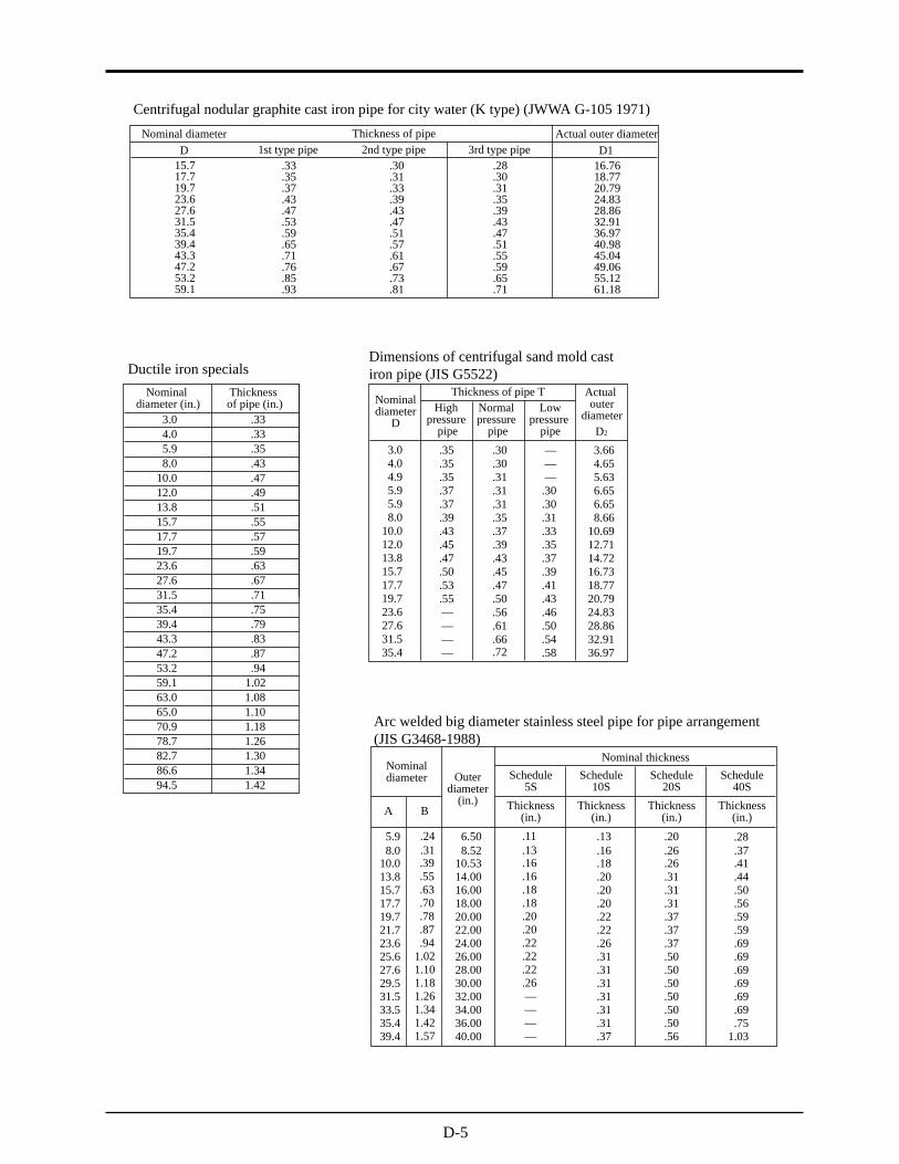
D-5
Arc welded big diameter stainless steel pipe for pipe arrangement(JIS G3468-1988)
Ductile iron specialsNominal
diameter (in.)Thicknessof pipe (in.)
3.0 .334.0 .335.9 .358.0 .43
10.0 .4712.0 .4913.8 .5115.7 .5517.7 .5719.7 .5923.6 .6327.6 .6731.5 .7135.4 .7539.4 .7943.3 .8347.2 .8753.2 .9459.1 1.0263.0 1.0865.0 1.1070.9 1.1878.7 1.2682.7 1.3086.6 1.3494.5 1.42
Nominaldiameter Outer
diameter(in.)
Nominal thicknessSchedule
5SSchedule
10SSchedule
20SSchedule
40S
Thickness(in.)
Thickness(in.)
Thickness(in.)
Thickness(in.)A B
13.8 .55 14.00 .16 .20 .31 .4415.7 .63 16.00 .18 .20 .31 .5017.7 .70 18.00 .18 .20 .31 .5619.7 .78 20.00 .20 .22 .37 .5921.7 .87 22.00 .20 .22 .37 .5923.6 .94 24.00 .22 .26 .37 .6925.6 1.02 26.00 .22 .31 .50 .6927.6 1.10 28.00 .22 .31 .50 .6929.5 1.18 30.00 .26 .31 .50 .6931.5 1.26 32.00 — .31 .50 .6933.5 1.34 34.00 — .31 .50 .6935.4 1.42 36.00 — .31 .50 .7539.4 1.57 40.00 — .37 .56 1.03
10.0 .39 10.53 .16 .18 .26 .418.0 .31 8.52 .13 .16 .26 .375.9 .24 6.50 .11 .13 .20 .28
Dimensions of centrifugal sand mold castiron pipe (JIS G5522)
.35 3.66
.35 4.653.0
.35 5.634.0
.37 6.654.9
.37 6.655.9
.39 8.665.9
.43 10.698.0
.45 12.7110.0
.47 14.7212.0
.50
.30
.30
.31
.31
.31
Nominaldiameter
D
Thickness of pipe T Actualouter
diameter
13.815.717.719.7
.53
.55
.35
.37
Highpressure
pipe
16.7318.7720.79
———
.30
.30
.31
.33
.35
.37
.39
.41
.43
D2
.39
.43
.45
.47
.5023.6 — 24.83.46.5627.6 — 28.86.50.6131.5 — 32.91.54.6635.4 — 36.97.58.72
Normalpressure
pipe
Lowpressure
pipe
Centrifugal nodular graphite cast iron pipe for city water (K type) (JWWA G-105 1971)
.33 16.76
.35 18.7715.7
.37 20.7917.7
.43 24.8319.7
.47 28.8623.6
.53 32.9127.6
.59 36.9731.5
.65 40.9835.4
.71 45.0439.4
.76
.30
.31
.33
.39
.43
Nominal diameter Thickness of pipe Actual outer diameter
43.347.253.259.1
.85
.93
.47
.51
1st type pipe 2nd type pipe
49.0655.1261.18
.28
.30
.31
.35
.39
.43
.47
.51
.55
.59
.65
.71
3rd type pipeD D1
.57
.61
.67
.73
.81

D-6
Hard vinyl chloride pipe for city water(JIS K6742-1975)
Arc welded carbon steel pipe (JIS G3457-1976)
Dimensions of centrifugal mold cast iron pipe(JIS G5523 1977)
.35 3.663.0
.35 4.654.0
.35 5.62
.37 6.654.9
.39 8.665.9
.43 10.698.0
.45 12.7110.012.0
Nominaldiameter
(in.)
Thickness of pipe T Actual outerdiameterHigh
pressure pipeNormal
pressure pipe D1
.30
.30
.31
.31
.35
.37
.39
Cast iron pipe for waste water (JIS G5525)
2.04.552.33.632.632.93
.71
3.22.79
3.50.87
3.81.94
4.091.021.101.181.26
Nominal diameter
.24
4.214.655.005.515.946.386.817.207.648.50
(A) (B)Outerdiameter(in.)
Thickness(in.)
.25 .28 .31 .34 .39 .41 .44 .47 .50 .52 .59 .63
13.815.717.719.721.723.625.627.629.531.533.535.439.443.347.253.259.163.070.978.7
1.341.421.571.731.892.132.362.522.833.15
2.172.482.803.123.433.754.064.374.695.005.315.63
2.402.633.103.453.804.134.494.845.205.55
2.673.063.443.834.214.605.005.395.796.186.576.977.72
4.605.085.555.986.466.937.407.878.359.29
5.475.986.507.017.528.038.629.06
10.0411.06
5.906.467.017.568.118.629.179.72
10.8311.93
6.306.897.488.078.669.259.84
10.4311.6112.76
6.737.367.998.629.259.88
10.4711.1012.3613.62
10.1610.8311.4612.7614.0615.3517.2819.2120.5123.11
11.6912.4013.1914.6816.1817.6419.8822.1323.6226.57
12.2813.0713.8615.4317.0118.5820.9423.2724.8427.99
10.2411.14 12.09 13.03 13.94
15.7117.48
14.8816.7718.62
29.57 31.46
14.0016.0018.0020.0022.0024.0026.0028.0030.0032.0034.0036.0040.0044.0048.0054.0060.0064.0072.0080.00
.24 2.42.0
.24 3.02.6
.24 3.4
.24 4.43.0
.24 5.44.0
.24 6.44.9
.28 8.45.98.0
Nominaldiameter
Actual innerdiameter
Actual outerdiameter
T D2
2.02.63.04.04.95.98.0
D1
Thicknessof pipe
Outer diameter Thickness
1.0 1.26 .141.2 1.50 .141.6 1.89 .162.0 2.36 .18
Nominal diameter
3.0 3.50 .234.0 4.49 .285.9 6.50 .38
.5 .71 .10
.8 1.02 .12

D-7
(a) Velocity of sound subject to change of temperature in water (32 to 212°F)
T°F
32 4600.9933 4617.2936 4632.9037 4648.8139 4664.0941 4678.9243 4693.4245 4707.5946 4721.4348 4734.9450 4748.1052 4760.9554 4773.52
Vft./s T°F Vft./s T°F Vft./s T°F Vft./s
55575961636466687072737577
4785.754797.664809.304820.624831.674842.434852.924863.124873.064882.714892.124901.274910.16
79 4918.8281 4927.2282 4935.3584 4943.2986 4950.9688 4958.4190 4965.6291 4972.6493 4979.4395 4985.99
.97 4992.3699 4998.49
100102104106108109111113115117118120122
5004.435010.175015.715021.025026.175031.135035.885040.445044.845049.045053.075056.915060.61
124 5064.09126 5067.44127 5070.62129 5073.60131 5076.46133 5079.11135 5081.64136 5084.00138 5086.23140 5088.26142 5090.17144 5091.94145147149151153154156158160162163165167
5093.545094.995096.335097.485098.535099.425100.175100.795101.285101.615101.845101.945101.88
169 5101.71171 5101.42172 5100.99174 5100.47176 5099.78178 5098.99180 5098.10181 5097.05183 5095.91185 5094.66187 5093.25189 5091.77190192194196198199201203205207208210212
5090.175088.435086.595084.665082.625080.465078.195075.805073.345070.755068.925065.275062.38
Note) T: temperature, V: velocity of sound
(b) Velocity of sound and density of various liquids
(c)Velocity of sound per piping material (d) Dynamic viscosity coefficient of various liquids
Name of liquid T°Fr oz./in. Vft./s3
6868
6868
68
686868
6868686868
6868
77
93
56
0.4571 0.5907
0.4125 0.6436
0.8598
0.6068 0.5366 0.5204
0.6391 0.92187.8609
0.6979 0.7305
0.3620 0.3781
0.4683
0.4643
0.5782
39035442
33005464
3283
380238743818
45533077475948313798
33853552
4343
4100
4789
68 0.7293 6307
Note) T: temperature, : density, V: velocity of sound
68 0.4564 3831
68 0.4060 390968 0.5036 4461
68 0.6384 4228
68 0.4504 421268 0.5973 4556
68 0.4652 401868 1.6712 3054
90.5 0.4967 467489.5 0.5233 440293 0.4770 4248
61 0.5782 4953
AcetoneAnilineAlcoholEtherEthylene glycoln-octaneo-xyleneChloroformChlorobenzeneGlycerinAcetic acidMethyl acetateEthyl acetateCyclohexaneDithionic acidHeavy waterCarbon tetrachlorideMercuryNitrobenzeneCarbon disulfideChloroformn-propyl alcoholn-pentanen-hexane
Light oilTransformer oilSpindle oilPetroleumGasolineWaterSea water (salinity: 35%)
Material Vft./s
Note) V: velocity of sound
IronSteelDuctile cast ironCast ironStainless steelCopperLeadAluminumBrassVinylchlorideAcrylicsFRP
MortarTar epoxyPolyethyleneTeflon
Name of liquid
Water
T°Fr oz./in. Vft./s n (´ 10 ft. /s)3 -6
6868686868
68686868686868686868
9093
56
0.4571 0.5907 0.4125 0.6436 0.8598
0.6068 0.5366 0.5204 0.6391 0.92187.8609
0.6979 0.7305 0.3620 0.3781
0.5233 0.4643
0.5782
39035442330054643283
3802387438184553307747594831379833853552
43434100
4789
1.33 5.79 1.1069.25 1.26
3.81 1.35 1.64 3.70 1.99 0.37 5.46 0.95 1.20 1.60
51.50 1.3 ~ 1.6
3.29(68°F)
68 0.7293 6307 38.98
Note) T: temperature, : density, V: velocity of soundn : kinematic viscosity
2
AcetoneAnilineEtherEthylene glycolChloroformGlycerinAcetic acidMethyl acetateEthyl acetateHeavy waterCarbon tetrachlorideMercuryNitrobenzeneCarbon disulfiden-pentanen-hexane
Spindle oilGasoline
1059710519
807110519
10106
87418219
8203
4068
8662
9843
74157120
6726
82196234