Ultrasonic Flowmeter for Air - Test & Measurement … · 2017-08-29 · Ultrasonic Flowmeter for...
4
21A1-E-0019a Ultrasonic Flowmeter for Air Type: FWD Abundant applicable pipe diameters Applicable pipe diameter 25mm up to 200mm. No energy loss due to no pressure loss Measurement principle is ultrasonic method. There is no pressure loss without protrusion in the pipe. No need of filter such as mist separator thanks to FWD has high resistance to oil mist Accurate flow rate measurement including oil mist. Strong durable and reliable to use. No need of power source installation work by means of battery driven Lithium-battery build-in type (approx. 10 years operating) is provided without painful wiring work of the power. Flow rate conversion available Conversion from an actual flow rate to a flow rate at normal conditions (0°C, 1 atm) or user-defined conditions. Capable of forward/reverse measurement and output Ideal for proper management for compressor etc…! Nominal diameter 40 to 80mm Nominal diameter 25 and 32mm Nominal diameter 100 to 200mm
Transcript of Ultrasonic Flowmeter for Air - Test & Measurement … · 2017-08-29 · Ultrasonic Flowmeter for...

21A1-E-0019a
Ultrasonic Flowmeter for AirType: FWD
Abundant applicable pipe diametersApplicable pipe diameter 25mm up to 200mm.
No energy loss due to no pressure lossMeasurement principle is ultrasonic method. There is no pressure loss without protrusion in the pipe.
No need of filter such as mist separator thanks to FWD has high resistance to oil mistAccurate flow rate measurement including oil mist. Strong durable and reliable to use.
No need of power source installation work by means of battery drivenLithium-battery build-in type (approx. 10 years operating) is provided without painful wiring work of the power.
Flow rate conversion availableConversion from an actual flow rate to a flow rate at normal conditions (0°C, 1 atm) or user-defined conditions.
Capable of forward/reverse measurement and output
Ideal for proper management for compressor etc…!
Nominal diameter40 to 80mm
Nominal diameter25 and 32mm
Nominal diameter100 to 200mm
Principle
Airflow rate measurement supported by ultrasonic method!"Visualization" is supported meeting customer's demands.
No energy loss due to no pressure loss.n Ultrasonic method is adopted as a measurement principle.n There is no pressure loss due to no protrusion in a pipe.
No need of power source installation work by means of battery driven.n Build-in battery type (10 years operating) is also provided which
eliminates painful power source installation work.Note) Battery driven type is to indicate only.
1: 60 Wide range abilityn Having wide range ability enables little amount of flow rate to be
measured accurately.Furthermore, it realize that wide rage with 1:400 from sensitive flow rate (beginning of the measuring flow rate) to maximum flow rate.
High durability thanks to it has strong resistance to oil and mist.n Strong structure to oil ,mist and fluid containing dust due to no moving parts.n Capable of using even with old pipe and refueling type compressor.
Note) In case of a large amount of oil and mist contained, a vertical piping is recommended to use.
Abundant output functions enables a system management/control.n Not only unit pulse but also 4 to 20mA DC analog output and upper /lower
alarm output are provided.Note) When 4 to 20mA DC analog output is selected, instantaneous flow rate,
pressure and temperature can be switched in the field.
Capable of forward/reverse measurement and output.n Capable of forward/reverse measurement and output according to
measurement setting.n Comprehending an using air rate where flows between factories, also
applicable to loop pipe.
Capable of detecting the air leakage.
Easy to read displayn LCD digital display with large size of characters allows to read easily and
capable of reading an accumulated flow rate and instantaneous flow rate simultaneously.Additionally, indication part can be rotated in 90 degrees in the field.
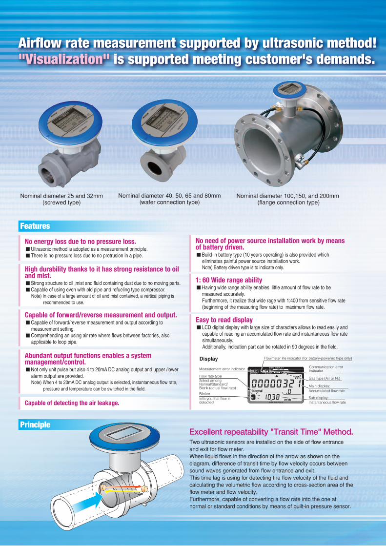
Excellent repeatability "Transit Time" Method.Two ultrasonic sensors are installed on the side of flow entrance and exit for flow meter.When liquid flows in the direction of the arrow as shown on the diagram, difference of transit time by flow velocity occurs between sound waves generated from flow entrance and exit.This time lag is using for detecting the flow velocity of the fluid and calculating the volumetric flow according to cross-section area of the flow meter and flow velocity.Furthermore, capable of converting a flow rate into the one at normal or standard conditions by means of built-in pressure sensor.
Features
Nominal diameter 25 and 32mm (screwed type)
Nominal diameter 100,150, and 200mm (flange connection type)
Nominal diameter 40, 50, 65 and 80mm(wafer connection type)
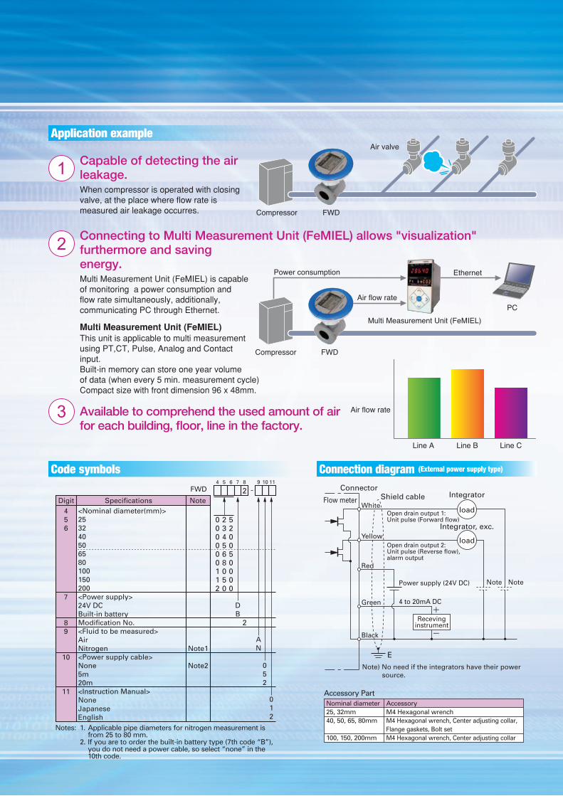
Display Flowmeter life indicator (for battery-powered type only)
Communication error indicatorMeasurement error indicator
Flow rate typeSelect amongNormal/Standard/Blank (actual flow rate)
Blinkertells you that flow isdetected
Accumulated flow rateMain display:
Gas type (Air or N2)
Sub display:Instantaneous flow rate
Airflow rate measurement supported by ultrasonic method!"Visualization" is supported meeting customer's demands.
Application example
Code symbols
Capable of detecting the air leakage.When compressor is operated with closing valve, at the place where flow rate is measured air leakage occurres.
1
Connecting to Multi Measurement Unit (FeMIEL) allows "visualization" furthermore and saving energy.Multi Measurement Unit (FeMIEL) is capable of monitoring a power consumption and flow rate simultaneously, additionally, communicating PC through Ethernet.
Multi Measurement Unit (FeMIEL)This unit is applicable to multi measurement using PT,CT, Pulse, Analog and Contact input.Built-in memory can store one year volume of data (when every 5 min. measurement cycle)Compact size with front dimension 96 x 48mm.
2
Available to comprehend the used amount of air for each building, floor, line in the factory.
3
Air valve
Compressor FWD
Power consumption
Air flow rate
Multi Measurement Unit (FeMIEL) PC
Compressor
Ethernet
FWD
Air valve
Compressor FWD
Power consumption
Air flow rate
Multi Measurement Unit (FeMIEL) PC
Compressor
Ethernet
FWD
Line A Line B Line C
Air flow rate
AN
052
7 8 9 10 114 5 6
2
2
520050000
234568050
000000112
DB
012
Specifications Note
FWD
Digit456
7
89
10
11
<Nominal diameter(mm)>253240506580100150200<Power supply>24V DCBuilt-in batteryModification No.<Fluid to be measured>AirNitrogen<Power supply cable>None5m20m<Instruction Manual>NoneJapaneseEnglish
Note1
Note2
Notes: 1. Applicable pipe diameters for nitrogen measurement is from 25 to 80 mm. 2. If you are to order the built-in battery type (7th code “B”), you do not need a power cable, so select “none” in the 10th code.
load
load
Recevinginstrument
4 to 20mA DC
Power supply (24V DC) Note Note
Connector
Flow meter
+
-
E
Note) No need if the integrators have their power source.
Open drain output 2: Unit pulse (Reverse flow), alarm output
Open drain output 1: Unit pulse (Forward flow)
Integrator, exc.
IntegratorShield cableWhite
Yellow
Red
Green
Black
Accessory PartNominal diameter Accessory 25, 32mm M4 Hexagonal wrench40, 50, 65, 80mm M4 Hexagonal wrench, Center adjusting collar, Flange gaskets, Bolt set100, 150, 200mm M4 Hexagonal wrench, Center adjusting collar
Connection diagram (External power supply type)
* Before using products in this catalog, be sure to read their instruction manuals in advance. Caution on Safety
Printed in Japan 2017-4FOLS
Global Sales SectionInstrumentation & Sensors Planning Dept.1, Fuji-machi, Hino-city, Tokyo 191-8502, Japanhttp://www.fujielectric.comPhone: +81-42-514-8930 Fax: +81-42-583-8275http://www.fujielectric.com/products/instruments/
Information in this catalog is subject to change without notice.
Specification
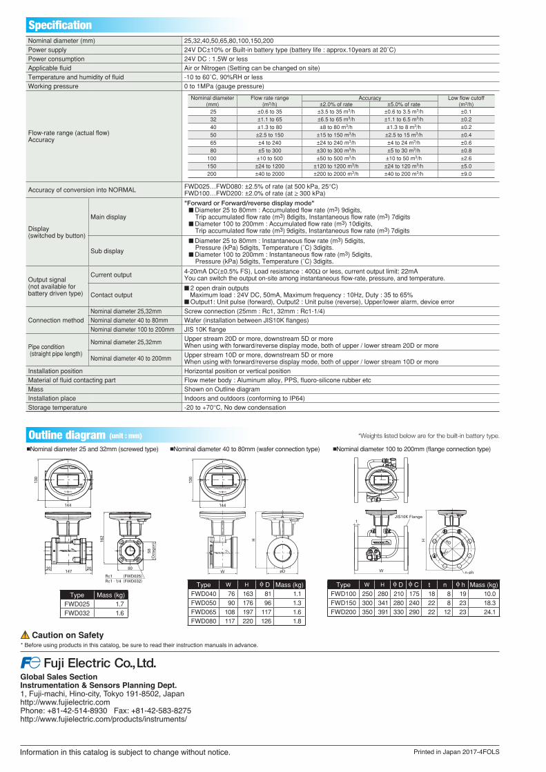
Outline diagram (unit : mm) *Weights listed below are for the built-in battery type.
162
58(O
ctag
on)
Rc1 (FWD025)Rc1 . 1/4 (FWD032)
130
147
144
20 20 80
H
W
øD
øC
t
H
130
W
144
øD
JIS10K Flange
n-øh
162
58(O
ctag
on)
Rc1 (FWD025)Rc1 . 1/4 (FWD032)
130
147
144
20 20 80
H
W
øD
øC
t
H
130
W
144
øD
JIS10K Flange
n-øh
162
58(O
ctag
on)
Rc1 (FWD025)Rc1 . 1/4 (FWD032)
130
147
144
20 20 80
H
W
øD
øC
t
H
130
W
144
øD
JIS10K Flange
n-øh
nNominal diameter 25 and 32mm (screwed type) nNominal diameter 40 to 80mm (wafer connection type) nNominal diameter 100 to 200mm (flange connection type)
Type Mass (kg)FWD025 1.7FWD032 1.6
Type W H f D Mass (kg)FWD040 76 163 81 1.1FWD050 90 176 96 1.3FWD065 108 197 117 1.6FWD080 117 220 126 1.8
Type W H f D f C t n f h Mass (kg)FWD100 250 280 210 175 18 8 19 10.0FWD150 300 341 280 240 22 8 23 18.3FWD200 350 391 330 290 22 12 23 24.1
Nominal diameter (mm) 25,32,40,50,65,80,100,150,200Power supply 24V DC±10% or Built-in battery type (battery life : approx.10years at 20˚C)Power consumption 24V DC : 1.5W or less Applicable fluid Air or Nitrogen (Setting can be changed on site) Temperature and humidity of fluid -10 to 60˚C, 90%RH or lessWorking pressure 0 to 1MPa (gauge pressure)
Flow-rate range (actual flow)Accuracy
Accuracy of conversion into NORMAL FWD025…FWD080: ±2.5% of rate (at 500 kPa, 25°C)FWD100…FWD200: ±2.0% of rate (at ≥ 300 kPa)
Display(switched by button)
Main display
"Forward or Forward/reverse display mode"n Diameter 25 to 80mm : Accumulated flow rate (m3) 9digits,
Trip accumulated flow rate (m3) 8digits, Instantaneous flow rate (m3) 7digitsn Diameter 100 to 200mm : Accumulated flow rate (m3) 10digits,
Trip accumulated flow rate (m3) 9digits, Instantaneous flow rate (m3) 7digits
Sub display
n Diameter 25 to 80mm : Instantaneous flow rate (m3) 5digits,Pressure (kPa) 5digits, Temperature (˚C) 3digits.
n Diameter 100 to 200mm : Instantaneous flow rate (m3) 5digits,Pressure (kPa) 5digits, Temperature (˚C) 3digits.
Output signal(not available for battery driven type)
Current output 4-20mA DC(±0.5% FS), Load resistance : 400Ω or less, current output limit: 22mAYou can switch the output on-site among instantaneous flow-rate, pressure, and temperature.
Contact outputn 2 open drain outputs
Maximum load : 24V DC, 50mA, Maximum frequency : 10Hz, Duty : 35 to 65%n Output1: Unit pulse (forward), Output2 : Unit pulse (reverse), Upper/lower alarm, device error
Connection methodNominal diameter 25,32mm Screw connection (25mm : Rc1, 32mm : Rc1-1/4)Nominal diameter 40 to 80mm Wafer (installation between JIS10K flanges)Nominal diameter 100 to 200mm JIS 10K flange
Pipe condition (straight pipe length)
Nominal diameter 25,32mm Upper stream 20D or more, downstream 5D or moreWhen using with forward/reverse display mode, both of upper / lower stream 20D or more
Nominal diameter 40 to 200mm Upper stream 10D or more, downstream 5D or moreWhen using with forward/reverse display mode, both of upper / lower stream 10D or more
Installation position Horizontal position or vertical positionMaterial of fluid contacting part Flow meter body : Aluminum alloy, PPS, fluoro-silicone rubber etcMass Shown on Outline diagramInstallation place Indoors and outdoors (conforming to IP64)Storage temperature -20 to +70°C, No dew condensation
Nominal diameter(mm)
Flow rate range(m3/h)
Accuracy Low flow cutoff(m3/h)±2.0% of rate ±5.0% of rate
25 ±0.6 to 35 ±3.5 to 35 m3/h ±0.6 to 3.5 m3/h ±0.132 ±1.1 to 65 ±6.5 to 65 m3/h ±1.1 to 6.5 m3/h ±0.240 ±1.3 to 80 ±8 to 80 m3/h ±1.3 to 8 m3/h ±0.250 ±2.5 to 150 ±15 to 150 m3/h ±2.5 to 15 m3/h ±0.465 ±4 to 240 ±24 to 240 m3/h ±4 to 24 m3/h ±0.680 ±5 to 300 ±30 to 300 m3/h ±5 to 30 m3/h ±0.8
100 ±10 to 500 ±50 to 500 m3/h ±10 to 50 m3/h ±2.6150 ±24 to 1200 ±120 to 1200 m3/h ±24 to 120 m3/h ±5.0200 ±40 to 2000 ±200 to 2000 m3/h ±40 to 200 m3/h ±9.0