NIST Experiences with Multipath Ultrasonic Flow Meters for ...

Ultrasonic Flow Measurement Technology

• History of the technology• Operating principles • Transducer installation• Pipe requirements• Fluid requirements• User interface and communications
Presentation Overview

History of the Technology
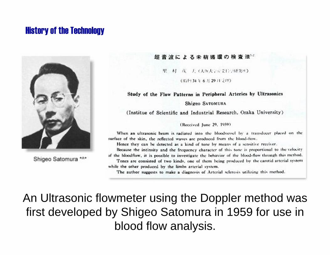
An Ultrasonic flowmeter using the Doppler method was first developed by Shigeo Satomura in 1959 for use in
blood flow analysis.
History of the Technology
History of the Technology
• In 1963, the first ultrasonic meters are developed for use in industrial applications.
• In 1972, the first U.S. manufactured ultrasonic meters are offered.

The 1998, AGA (American Gas Institute) approves Ultrasonic meters for use in gas custody transfer applications.
History of the Technology
A multi-path ultrasonic flowmeter for gas measurement.

Operating Principles

Operating Principles
• High frequency sound.• Both microphone and speaker.• Both liquid (fluid) and gas.• No moving parts.

Two distinctly different types of operating principles are used in most ultrasonic flow measurement applications…
Resulting in much confusion!
Operating Principles
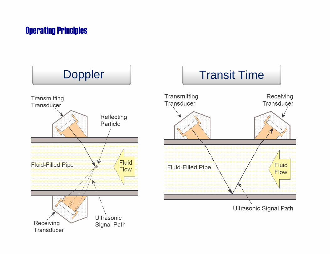
Doppler Transit Time
Operating Principles

Operating Principles
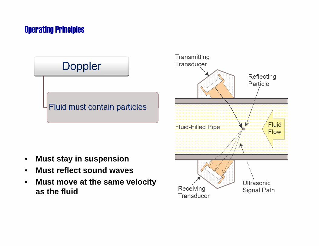
• Must stay in suspension• Must reflect sound waves• Must move at the same velocity
as the fluid
Operating Principles

Operating Principles

Operating Principles

Doppler phase shift
Operating Principles

Operating Principles

Operating Principles

Operating Principles

Transit-Time pulse burst
Operating Principles

Onset of the wave (or where is that guy with the red hat?)
Operating Principles

Where is that guy with the red hat?
Operating Principles

Onset of the wave (finding the guy with the red hat)
Operating Principles
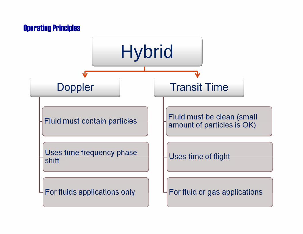
HybridOperating Principles

Transducer Installation
Transducer Installation
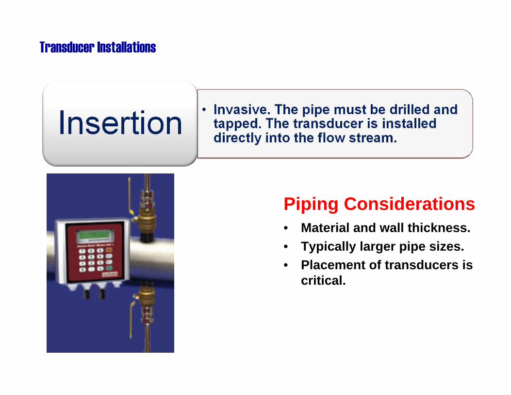
Transducer Installations
Piping Considerations• Material and wall thickness.• Typically larger pipe sizes.• Placement of transducers is
critical.

Piping Considerations• Flanged connections.• Typically smaller pipe sizes.• Transducers are pre-
installed.
Transducer Installations

Piping Considerations• Accurate measurement and
placement is required.• Pipe material and dimensions
must be known.• Acoustic coupling material is
required.
Transducer Installation

Separation Distance• Accurate placement is
important.• The distance between the
transducers must be correct.
• The transducers must be properly aligned.
Transducer Installation

Pipe measurements• Correct pipe OD and ID
measurement is required.• The pipe inside and outside
surface must be clean and smooth.
• The beam angle changes as it passes through the various materials.
Transducer Installation

Acoustic coupling• A special gasket or other
coupling material is required.
• Silicone sealant is often used.
Transducer Installation
Pipe Requirements
• Materials• Dimensions• Liners• Coatings• Straight lengths
Clamp-on Transducer Pipe Requirements
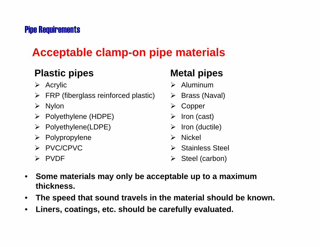
Acceptable clamp-on pipe materials
Plastic pipesAcrylic FRP (fiberglass reinforced plastic)Nylon Polyethylene (HDPE)Polyethylene(LDPE) Polypropylene PVC/CPVC PVDF
Metal pipesAluminum Brass (Naval) Copper Iron (cast) Iron (ductile) Nickel Stainless Steel Steel (carbon)
• Some materials may only be acceptable up to a maximum thickness.
• The speed that sound travels in the material should be known.• Liners, coatings, etc. should be carefully evaluated.
Pipe Requirements

For high accuracy, straight lengths of pipe needed to reduce swirl patterns and vortices.
• Multi-path units are even less susceptible to flow disturbances.
Pipe Requirements

Pipe Requirements
• Less straight pipe lengths needed than paddlewheel and other insertion type meters.
• Larger percentage of fluid effects the flow measurement.
Ultrasonic meters offer good resistance to swirl patterns

Fluid Requirements
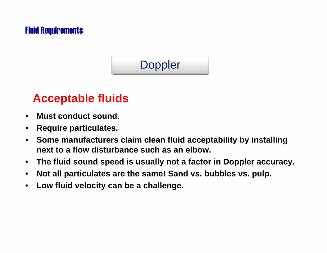
Acceptable fluids• Must conduct sound.• Require particulates.• Some manufacturers claim clean fluid acceptability by installing
next to a flow disturbance such as an elbow.• The fluid sound speed is usually not a factor in Doppler accuracy.• Not all particulates are the same! Sand vs. bubbles vs. pulp.• Low fluid velocity can be a challenge.
Doppler
Fluid Requirements

Acceptable fluids• Theoretically, any fluid that can conduct sound.• Typically acceptable with up to 10% particulates.• Some fluids can be used with both Doppler and Transit Time
methods.• Fluid sound speed can be a factor in Transit Time accuracy. • Temperature will effect the fluid sound speed.• The larger the pipe the better!• Low fluid velocities are typically not a challenge.
Transit Time
Fluid Requirements

User Interfaceand
Communications

• Flow rate and flow total.• Velocity.• Update time.• Averaging.
User Interface and Communications
Display

• Portable clamp-on units for system testing.• Power requirements. • Battery life an issue.• Fixed units often include security
passwords and robust enclosure designs.
User Interface and Communications
Portable or fixed in place

• 4-20 mA analog signal.• High speed digital pulse.• Contact closures.• Relays.
User Interface and Communications
Output signals

• Serial ports.– RS-232– RS-485– USB
• Protocols.– Modbus– Profibus– Foundation Fieldbus– HART
• Ethernet connection.• Proprietary software.
User Interface and Communications
Smart (er) communications

• Data logging.• Process control.• Alarms.
User Interface and Communications
Other features

Re-cap
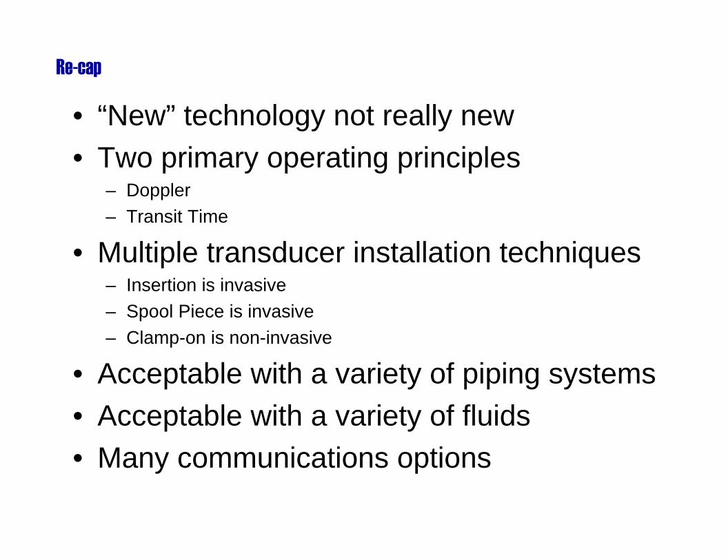
• “New” technology not really new• Two primary operating principles
– Doppler– Transit Time
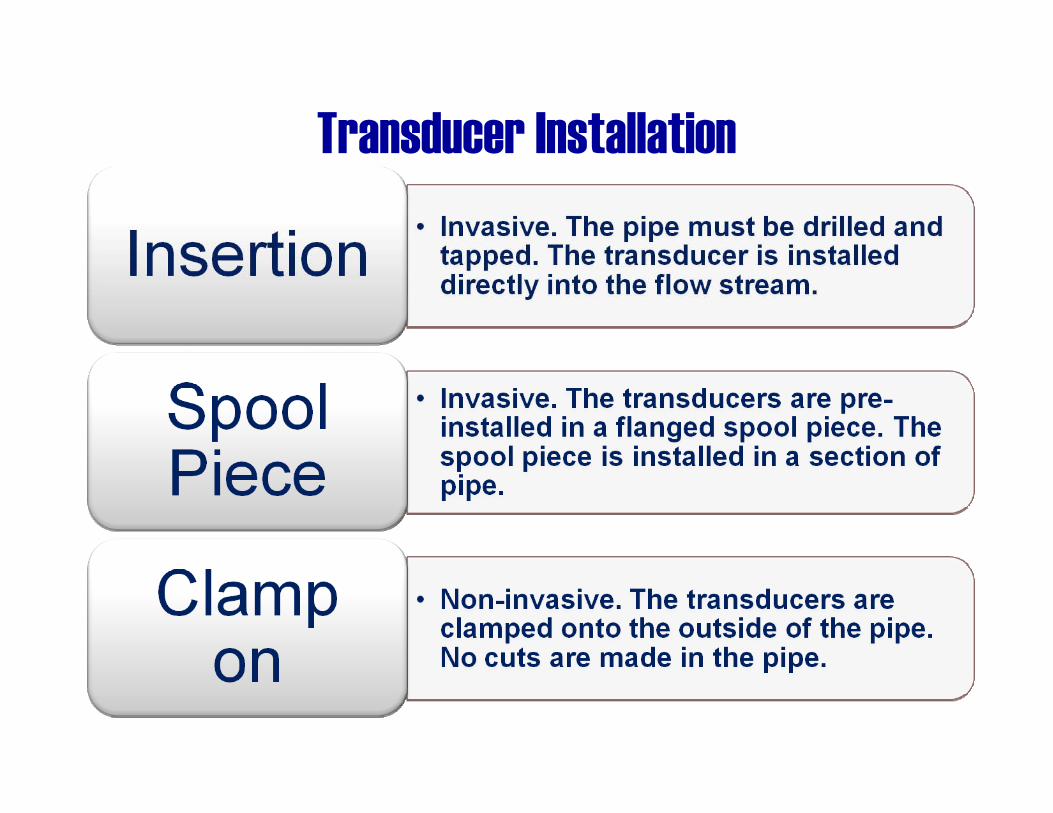
• Multiple transducer installation techniques– Insertion is invasive– Spool Piece is invasive– Clamp-on is non-invasive
• Acceptable with a variety of piping systems• Acceptable with a variety of fluids• Many communications options
Re-cap

Ultrasonic Flow Measurement Technology
Thank You!