ULTRASONIC / ENS - CLIMATE. CUSTOMIZED. |...
71
AIRCONDITIONING ULTRASONIC / ENS TECHNICAL MANUAL - ENS INDEX 71.1-2 Edition 2.97 Copyright STULZ GmbH 02/1997
Transcript of ULTRASONIC / ENS - CLIMATE. CUSTOMIZED. |...
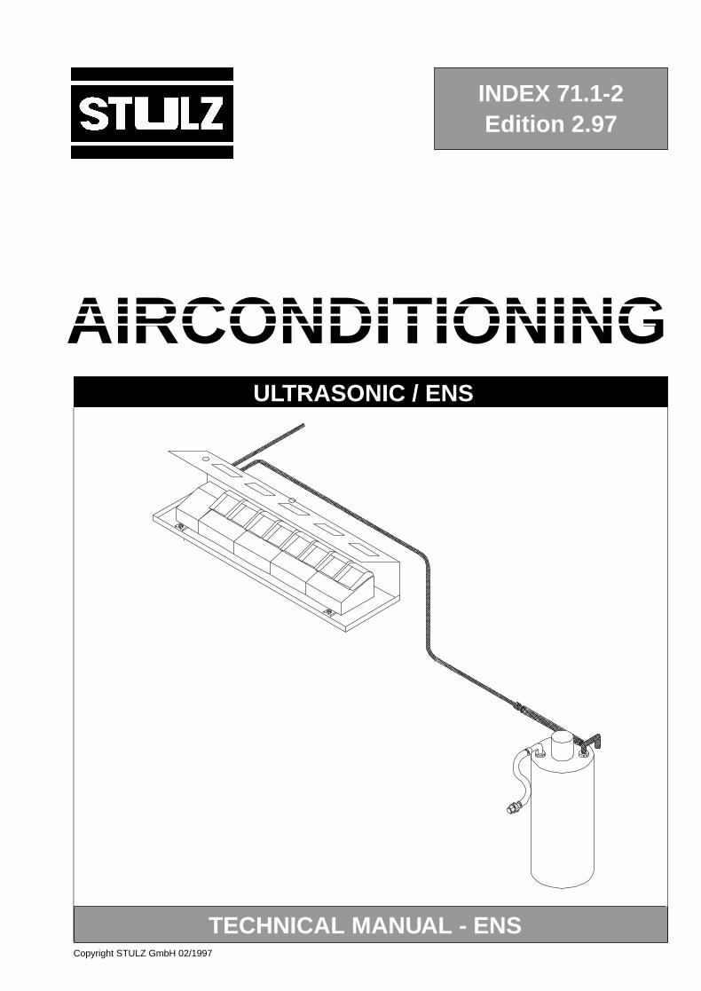
AIRCONDITIONINGULTRASONIC / ENS
TECHNICAL MANUAL - ENS
INDEX 71.1-2Edition 2.97
Copyright STULZ GmbH 02/1997
ULTRASONIC
2Copyright STULZ GmbH 02/1997
TABLE OF CONTENTS
Page
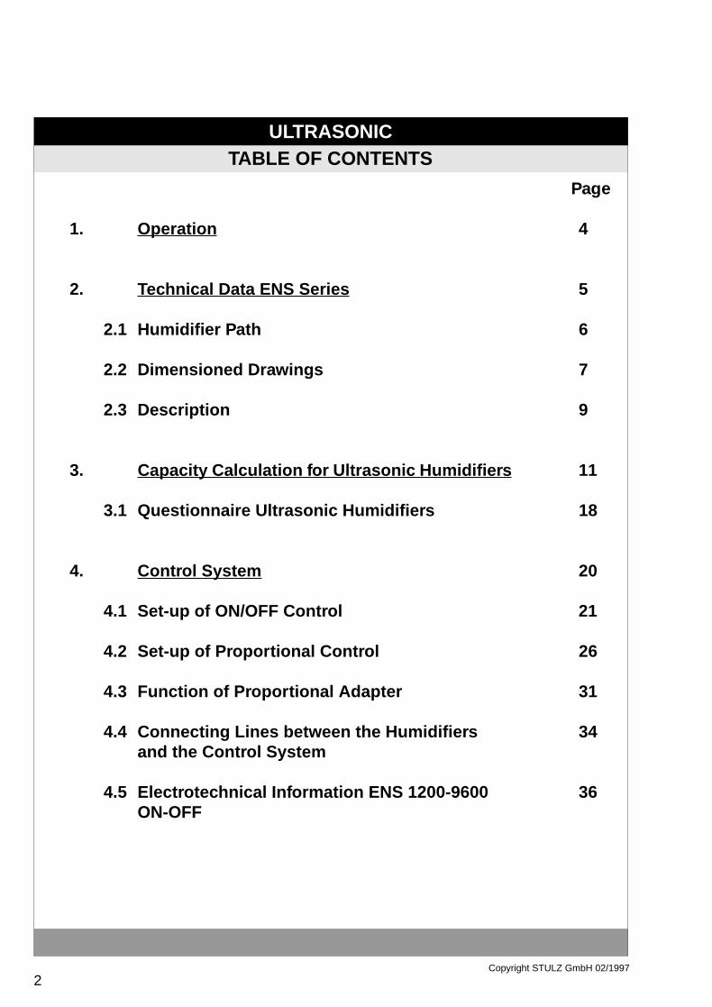
1. Operation 4
2. Technical Data ENS Series 5
2.1 Humidifier Path 6
2.2 Dimensioned Drawings 7
2.3 Description 9
3. Capacity Calculation f or Ultrasonic Humidifier s 11
3.1 Questionnaire Ultrasonic Humidifiers 18
4. Contr ol System 20
4.1 Set-up of ON/OFF Control 21
4.2 Set-up of Proportional Control 26
4.3 Function of Proportional Adapter 31
4.4 Connecting Lines between the Humidifiers 34and the Control System
4.5 Electrotechnical Information ENS 1200-9600 36ON-OFF
ULTRASONIC
3Copyright STULZ GmbH 02/1997
TABLE OF CONTENTS
Page
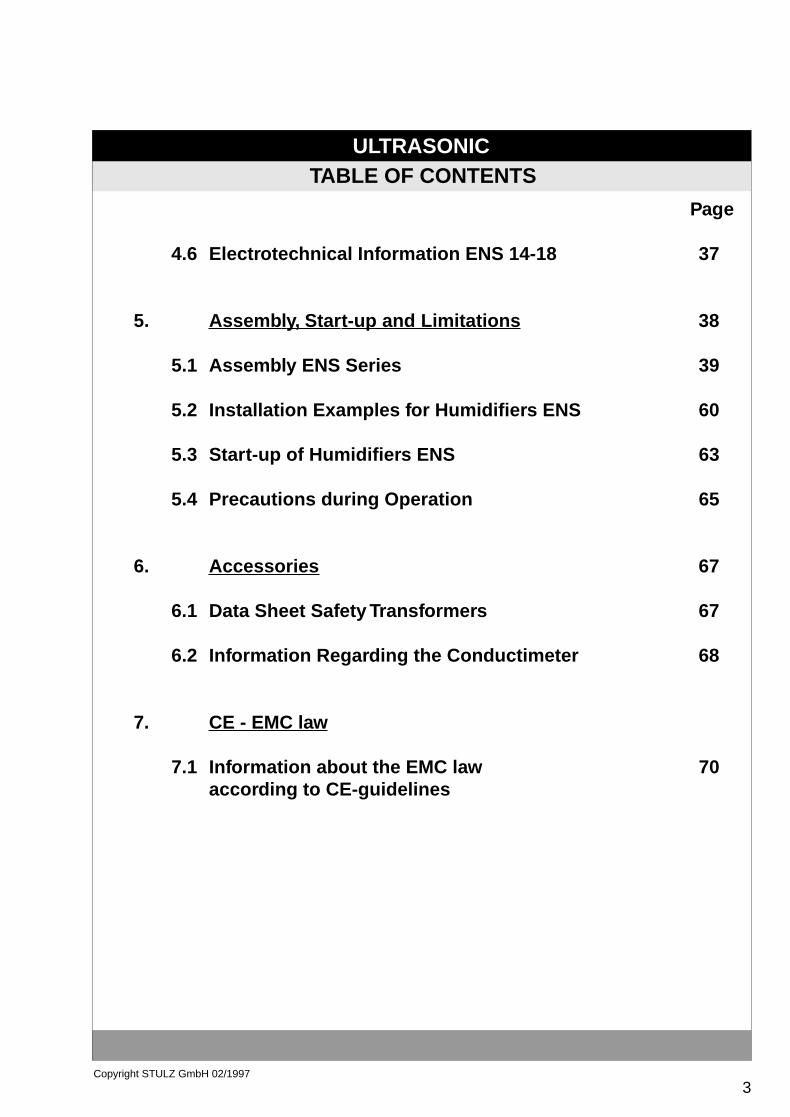
4.6 Electrotechnical Information ENS 14-18 37
5. Assemb ly, Star t-up and Limitations 38
5.1 Assembly ENS Series 39
5.2 Installation Examples for Humidifiers ENS 60
5.3 Start-up of Humidifiers ENS 63
5.4 Precautions during Operation 65
6. Accessories 67
6.1 Data Sheet Safety Transformers 67
6.2 Information Regarding the Conductimeter 68
7. CE - EMC law
7.1 Information about the EMC law 70according to CE-guidelines
ULTRASONIC
4Copyright STULZ GmbH 02/1997
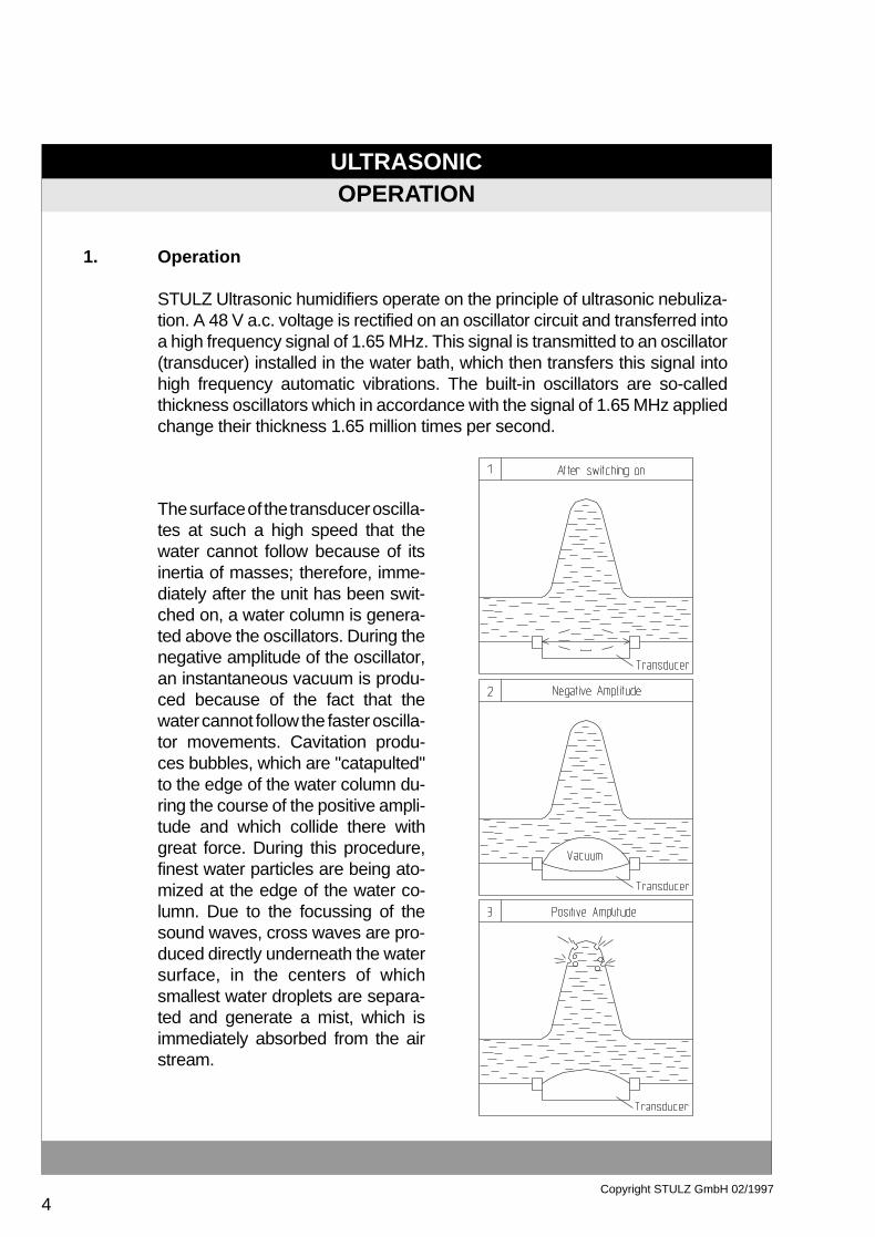
1. Operation
STULZ Ultrasonic humidifiers operate on the principle of ultrasonic nebuliza-tion. A 48 V a.c. voltage is rectified on an oscillator circuit and transferred intoa high frequency signal of 1.65 MHz. This signal is transmitted to an oscillator(transducer) installed in the water bath, which then transfers this signal intohigh frequency automatic vibrations. The built-in oscillators are so-calledthickness oscillators which in accordance with the signal of 1.65 MHz appliedchange their thickness 1.65 million times per second.
The surface of the transducer oscilla-tes at such a high speed that thewater cannot follow because of itsinertia of masses; therefore, imme-diately after the unit has been swit-ched on, a water column is genera-ted above the oscillators. During thenegative amplitude of the oscillator,an instantaneous vacuum is produ-ced because of the fact that thewater cannot follow the faster oscilla-tor movements. Cavitation produ-ces bubbles, which are "catapulted"to the edge of the water column du-ring the course of the positive ampli-tude and which collide there withgreat force. During this procedure,finest water particles are being ato-mized at the edge of the water co-lumn. Due to the focussing of thesound waves, cross waves are pro-duced directly underneath the watersurface, in the centers of whichsmallest water droplets are separa-ted and generate a mist, which isimmediately absorbed from the airstream.
OPERATION
ULTRASONIC
5Copyright STULZ GmbH 02/1997
TECHNICAL DATA ENS TYPE
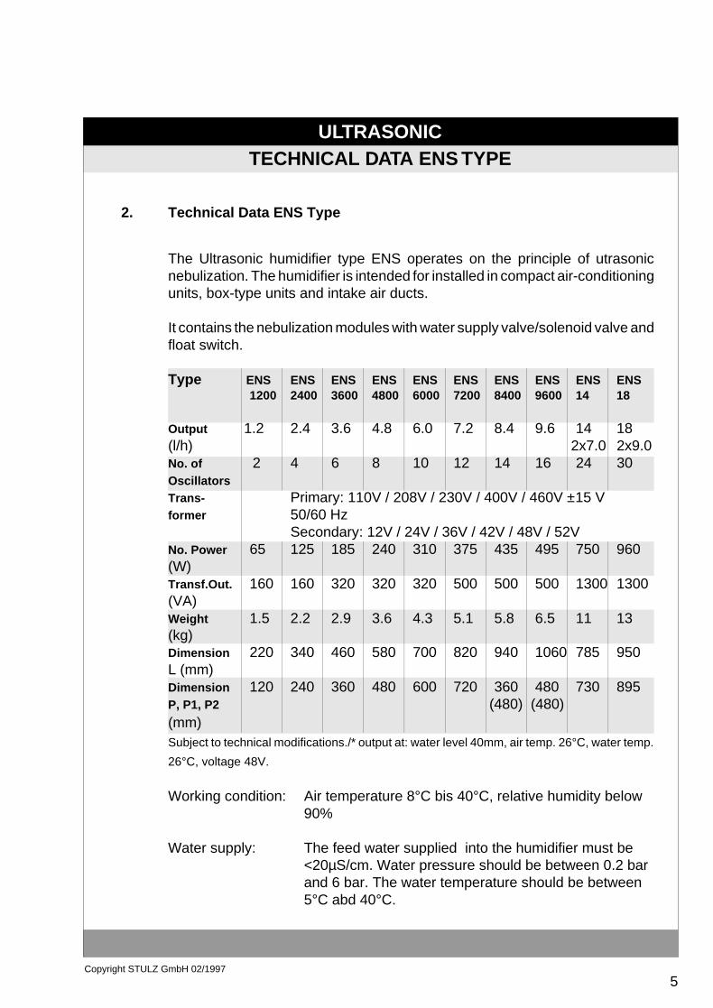
2. Technical Data ENS Type
The Ultrasonic humidifier type ENS operates on the principle of utrasonicnebulization. The humidifier is intended for installed in compact air-conditioningunits, box-type units and intake air ducts.
It contains the nebulization modules with water supply valve/solenoid valve andfloat switch.
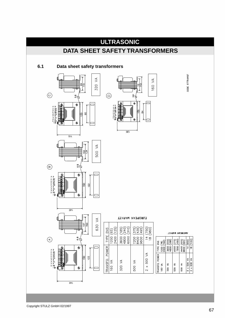
Type ENS ENS ENS ENS ENS ENS ENS ENS ENS ENS1200 2400 3600 4800 6000 7200 8400 9600 14 18
Output 1.2 2.4 3.6 4.8 6.0 7.2 8.4 9.6 14 18(l/h) 2x7.0 2x9.0No. of 2 4 6 8 10 12 14 16 24 30OscillatorsTrans- Primary: 110V / 208V / 230V / 400V / 460V ±15 Vformer 50/60 Hz
Secondary: 12V / 24V / 36V / 42V / 48V / 52VNo. Power 65 125 185 240 310 375 435 495 750 960(W)Transf.Out. 160 160 320 320 320 500 500 500 1300 1300(VA)Weight 1.5 2.2 2.9 3.6 4.3 5.1 5.8 6.5 11 13(kg)Dimension 220 340 460 580 700 820 940 1060 785 950L (mm)Dimension 120 240 360 480 600 720 360 480 730 895P, P1, P2 (480) (480)(mm)Subject to technical modifications./* output at: water level 40mm, air temp. 26°C, water temp.
26°C, voltage 48V.
Working condition: Air temperature 8°C bis 40°C, relative humidity below90%
Water supply: The feed water supplied into the humidifier must be<20µS/cm. Water pressure should be between 0.2 barand 6 bar. The water temperature should be between5°C abd 40°C.

ULTRASONIC
6Copyright STULZ GmbH 02/1997
Humidifier PathThe length of the humidifier path is dependent on different factors.
- even distribution of the mist in the airflow- air temperature- relative air humidity- air speed
The following diagram for the determation of the humidifier path contains standardvalues dependent on the most important parameters. (Air temperature 18°C to24°C). The tolerance is approx. ± 0.5 m.
If no place is available for the humidifier path, use of a mist collector is possible. Thesmaller the distance to the mist collector, the larger the loss effect of the humidifierand the more water is drained off into the pan, which has to be drained off forhygienic reasons. Another possibility to reduce the humidifier path is the employ-ment of a proportional control. With this control, the output of the humidifiers isreduced dependent on the requirements in more than 90% of the operating timeand therefore reduces the humidifier path, saves the oscillators and maintains aneven distribution of the mist even in operation under partial load.
TECHNICAL DATA ENS SERIES
2.1
ULTRASONIC
7Copyright STULZ GmbH 02/1997
TECHNICAL DATA ENS SERIES
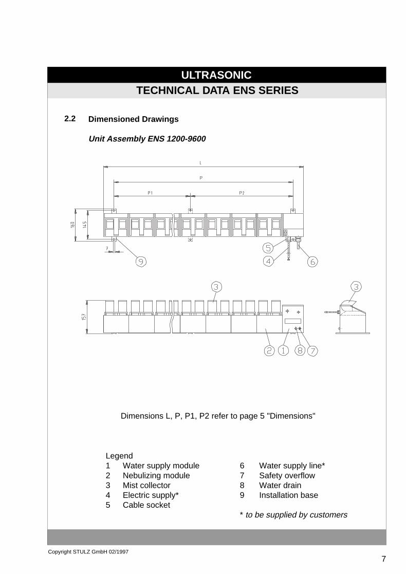
Dimensioned Drawings
Unit Assembly ENS 1200-9600
Dimensions L, P, P1, P2 refer to page 5 "Dimensions"
Legend 1 Water supply module 2 Nebulizing module 3 Mist collector 4 Electric supply* 5 Cable socket
6 Water supply line*7 Safety overflow8 Water drain9 Installation base
* to be supplied by customers
2.2
ULTRASONIC
8Copyright STULZ GmbH 02/1997
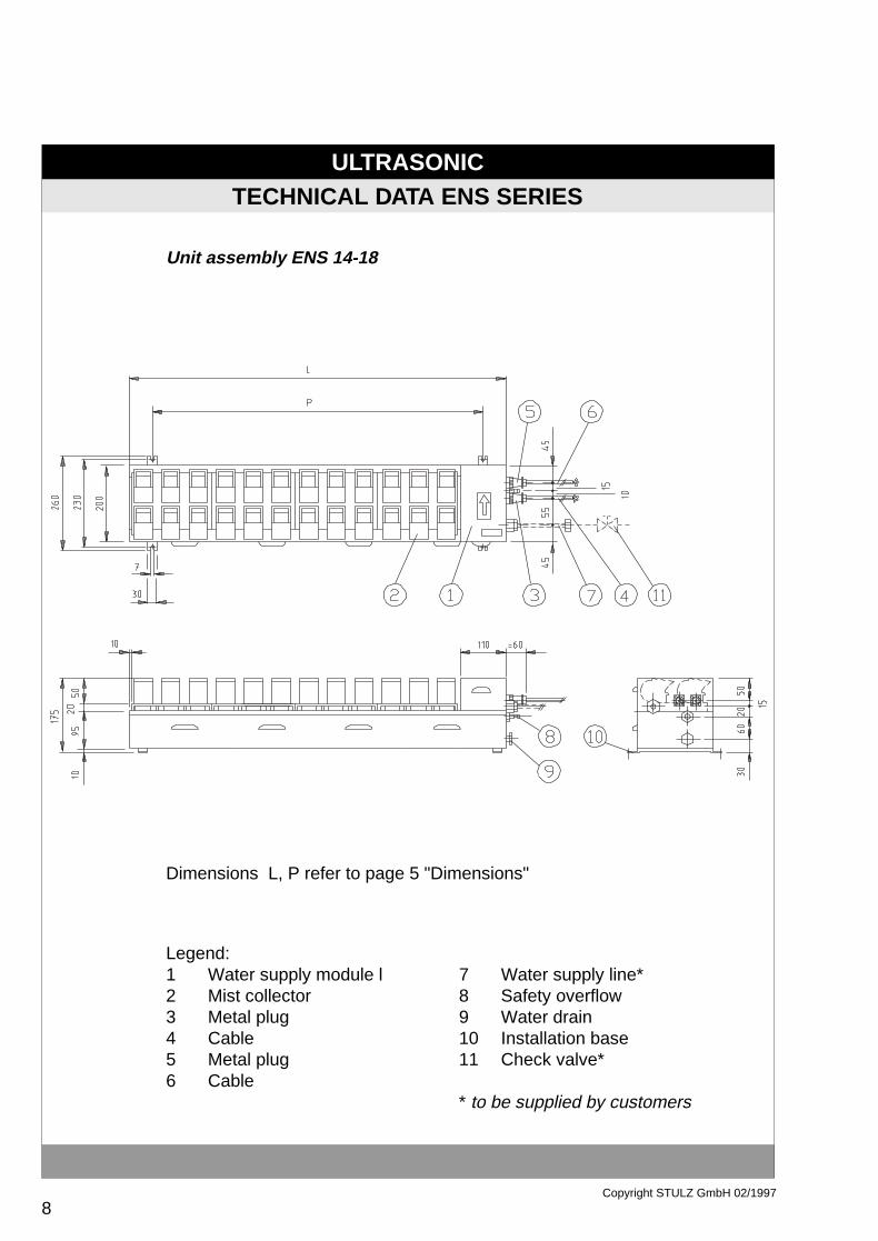
Unit assembly ENS 14-18
TECHNICAL DATA ENS SERIES
Dimensions L, P refer to page 5 "Dimensions"
Legend:1 Water supply module l 7 Water supply line*2 Mist collector 8 Safety overflow3 Metal plug 9 Water drain4 Cable 10 Installation base5 Metal plug 11 Check valve*6 Cable
* to be supplied by customers
ULTRASONIC
9Copyright STULZ GmbH 02/1997
TECHNICAL DATA ENS SERIES
2.3
Unit Description
Safety Appliances
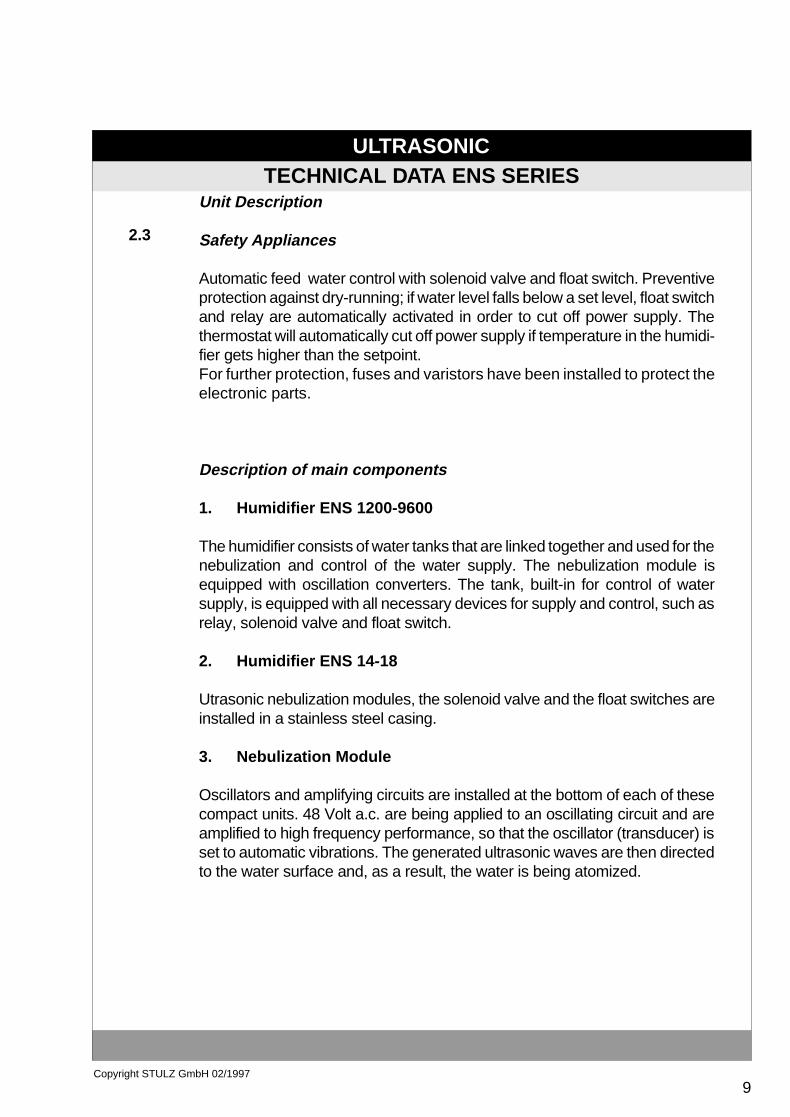
Automatic feed water control with solenoid valve and float switch. Preventiveprotection against dry-running; if water level falls below a set level, float switchand relay are automatically activated in order to cut off power supply. Thethermostat will automatically cut off power supply if temperature in the humidi-fier gets higher than the setpoint.For further protection, fuses and varistors have been installed to protect theelectronic parts.
Description of main components
1. Humidifier ENS 1200-9600
The humidifier consists of water tanks that are linked together and used for thenebulization and control of the water supply. The nebulization module isequipped with oscillation converters. The tank, built-in for control of watersupply, is equipped with all necessary devices for supply and control, such asrelay, solenoid valve and float switch.
2. Humidifier ENS 14-18
Utrasonic nebulization modules, the solenoid valve and the float switches areinstalled in a stainless steel casing.
3. Nebulization Module
Oscillators and amplifying circuits are installed at the bottom of each of thesecompact units. 48 Volt a.c. are being applied to an oscillating circuit and areamplified to high frequency performance, so that the oscillator (transducer) isset to automatic vibrations. The generated ultrasonic waves are then directedto the water surface and, as a result, the water is being atomized.
ULTRASONIC
10Copyright STULZ GmbH 02/1997
TECHNICAL DATA ENS SERIES
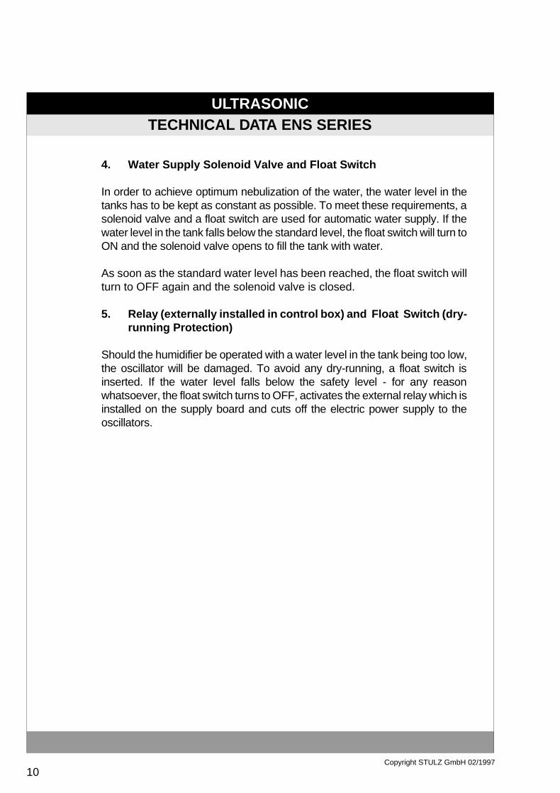
4. Water Supply Solenoid Valve and Float Switch
In order to achieve optimum nebulization of the water, the water level in thetanks has to be kept as constant as possible. To meet these requirements, asolenoid valve and a float switch are used for automatic water supply. If thewater level in the tank falls below the standard level, the float switch will turn toON and the solenoid valve opens to fill the tank with water.
As soon as the standard water level has been reached, the float switch willturn to OFF again and the solenoid valve is closed.
5. Relay (externally installed in control box) and Float Switch (dry-running Protection)
Should the humidifier be operated with a water level in the tank being too low,the oscillator will be damaged. To avoid any dry-running, a float switch isinserted. If the water level falls below the safety level - for any reasonwhatsoever, the float switch turns to OFF, activates the external relay which isinstalled on the supply board and cuts off the electric power supply to theoscillators.

ULTRASONIC
11Copyright STULZ GmbH 02/1997
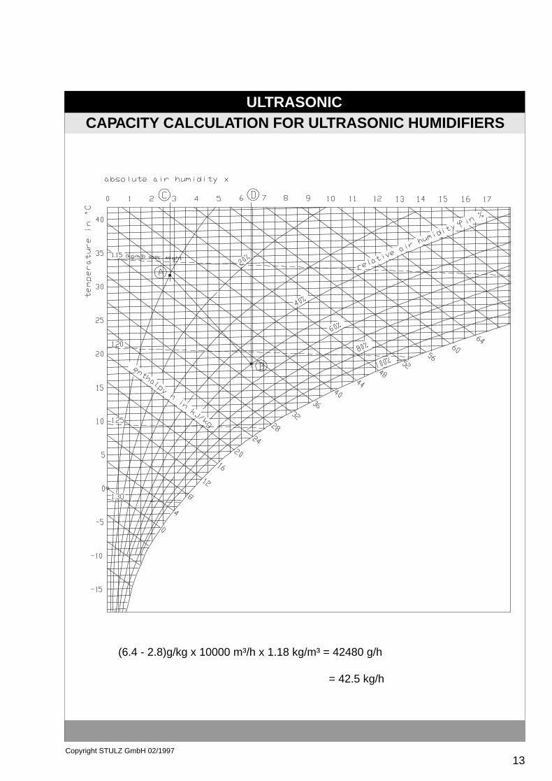
The two air conditions are entered into the h-x digram (point A and point BDraw a vertical line from A to edge measurement "x" point CDraw a vertical line from B to edge measurement "x" point DThen calculate the humidifier output:
>Point C = 2.8 g/kg air>Point D = 6.4 g/kg air>Difference = 3,6 (g Water)/(kg air) ( D - C )>Multiply the predetermined air volume (10.000 m³/hour) with the average air density (1,18 kg/m³) 10.000 m³/hour x 1,18 kg/m³ = 11.800 kg/hour>Multiply the difference of the water content in the air with the air weight/hour 3,6 g/kg x 11800 kg/hour = 42.480 g/hour
humidifier output = 42,5 kg/hour
The most favorable type of combinations is now chosen from the deliveryrange. The most frequent selection criteria are:
>Length of the ENS humidifier at the predetermined depth of the air treatment.>Number of ENS humidifiers, because of number of fixing fixing divices, water supply lines and electric control.
In the example given, 2 off ENS 14 have been chosen. ( 3 x 14 kg/hour =42 kg/hour )
CAPACITY CALCULATION FOR ULTRASONIC HUMIDIFIERS
Capacity Calculation for Ultrasonic Humidifiers
Basis of the capacity calculation for ULTRASONIC humidifiers is the que-stionnaire listed under chapter 3.1. Provided that this questionnaire has beencompletely been filled in, it will contain all data necessary for the calculation.
Example 1:
3.
LE = Air intake before humidification = 31.5°C / 10% r.h.LA = Air outlet after humidification = 18.0°C / 50% r.h.
Air volume = 10.000 m³/hour
These values have to be chosen for the most unfavorable conditions, whichusually exist in winter at lowest outer temperatures.
1.2.3.4.
5.

ULTRASONIC
12Copyright STULZ GmbH 02/1997
CAPACITY CALCULATION FOR ULTRASONIC HUMIDIFIERS
6. Determine the net cross section and the air speed in the duct or airtreatment unit
>Determine the free cross section for the air treatment unit frommanufacturers' information.For the calcualtion example: Height: 1100 mm
Depth: 1300 mmHeight x deptch = 1.1 m x 1.3 m = 1.43 m² cross section
>Determine the reduction of the free cross section caused by thehumidfiers
Example:
1,43 m² - (3 x 0,137) = 1,02 m²
= free cross section underconsideration of the threehumidifiers ENS 14
>Determine the air speedAir volume (m³/h) / 3600 = m³/s
m³/sfree cross section (m²)
Example:
10.000 m³/h 3.600
2,78 m³/s1,02 m²
The calculated air speed of 2,73 m/s is within the permissiblelimits of 1,5 - 3 m/s.
Type
ENS 1200ENS 2400ENS 3600ENS 4800ENS 6000ENS 7200ENS 8400ENS 9600ENS 14ENS 18
C.Sectiont
0,035 m²0,053 m²0,072 m²0,091 m²0,11 m²0,129 m²0,148 m²0,166 m²0,137 m²0,166 m²
= m/s
= 2,78 m³/s
= 2,73 m/s
ULTRASONIC
13Copyright STULZ GmbH 02/1997
CAPACITY CALCULATION FOR ULTRASONIC HUMIDIFIERS
(6.4 - 2.8)g/kg x 10000 m³/h x 1.18 kg/m³ = 42480 g/h
= 42.5 kg/h

ULTRASONIC
14Copyright STULZ GmbH 02/1997
7. Determination of the Humidifier Path
The length of the humidifier path is dependent on different facors:- Even distribution of the mist in the airflow- Air temperature- Air relative humidity- Air speed
The following diagram for the determination of the humidifier path containsexperience values dependent on the most important parameters. Thediagram is valid for the temperature range from 18°C to 24°C.
Should no place be available for the humidifier path, the use of a mistcollector is possible. The smaller the distance to the mist collector, thelarger the loss effect of the humidifier and the more water is drained off intothe pan, which has to be drained off for hygienic reasons.
CAPACITY CALCULATION FOR ULTRASONIC HUMIDIFIERS

ULTRASONIC
15Copyright STULZ GmbH 02/1997
CAPACITY CALCULATION FOR ULTRASONIC HUMIDIFIERS
As the dimensioning of the humidifier output is always made for the mostunfavorable operating status, the humidifier is over-dimensioned in up to 90%of the operating time. (In a comfort air conditioning unit, the dimensioning ismade for the lowest temperature in winter, which usually occurrs during thenight and usually does not last for more than 10 hours/year).
A proportional control reduces the output to more than 90% of the operatingtime of the humidifier according to demand and thus reduces the humidifierpath, and therefore saves the oscillators and maintains an even distribution ofthe mist also in operation under partial load.
2. Example Humidification of an office room
Humidification of an office room with Ultrasonic humidifiers installed in the airintake duct (recirculating operation with outer air portion)
- Volume flow VL= 2000 m³/h- Outer air condition in winter LW= -10 °C / 90 % r.h.- Desired ambient temperature LR= 20 °C / 60 % r.h.- Outer air portion 50%
The air conditions LW and LR are drawn into the h-x diagram and both pointsare connected with each other.

ULTRASONIC
16Copyright STULZ GmbH 02/1997
CAPACITY CALCULATION FOR ULTRASONIC HUMIDIFIERS
The mixing point for the outer air percentage 50% is half of the connectingstraight line between LW and LR. From the mixing point M and from LR aperpendicular is drawn at the upper edge of the h-x diagram. On basis of theperpendicular line at point M, a water content of 5.2 g/kg and, at point LR
of 8,8 g/kg can be determined.This results in an ∆x of 8.8 g/kg - 5.2 g/kg = 3.6 g/kg. This means that 3.6 gof water per kg hourly recirculated air have to be provided.
The mass of the hourly recirculated air results from the volume flow (2000m³/h) multiplied by the specific weight ρ of the air(1,20 kg/m³).
VL x ρ = 2000 m³/h x 1,20 kg/m³ = 2400 kg/h
As 3,6 g of water have to be added hourly per kg of air, the output of thehumidifier can be calculated as follows:
2400 kg/h x 3.6 g/kg = 8640 g/h

ULTRASONIC
17Copyright STULZ GmbH 02/1997
CAPACITY CALCULATION FOR ULTRASONIC HUMIDIFIERS
Note:
STULZ ULTRASONIC humidifiers atomize water into smallest water dro-plets (< 0,001 mm).The mist (aerosols) generated takes away heat from the ambient air (enthal-py) and changes its state of aggregation from liquid to gaseous. Because ofthis "adiabatic" behavior (heat absoption from the ambient air), the ambient airin cooled down.
Example:
- Air conditon before humidification: Temperature 25 °Crelative humidity 30 %
- Moisture addition of ∆x= 3 g/kg
Condition of the air after humidification: Temperature 18 °Crelative humidity 70 %
ULTRASONIC
18Copyright STULZ GmbH 02/1997
3.1
QUESTIONNAIRE FOR ULTRASONIC HUMIDIFIERS
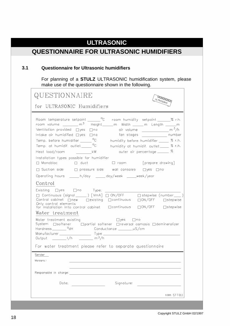
Questionnaire for Ultrasonic humidifiers
For planning of a STULZ ULTRASONIC humidification system, pleasemake use of the questionnaire shown in the following.

ULTRASONIC
19Copyright STULZ GmbH 02/1997
KLIMATECHNIK GmbH

ULTRASONIC
20Copyright STULZ GmbH 02/1997
CONTROL SYSTEM
4. Control System
For operation of the Ultrasonic humidifiers, an external control box has to beprovided. Together with the transformer required for operation, contactorrelays, the main switch, strip terminals and the proportional adapter, if requi-red, controller or the conductimeter have to be integrated into the control box.
Control of the humidifiers can either be ON/OFF control, continuous orproportional control. The control system should be suitably adapted to theproject in question.
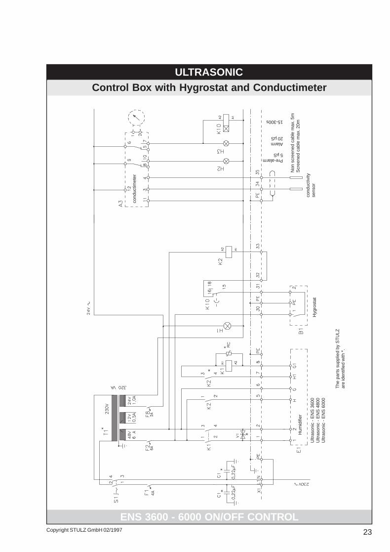
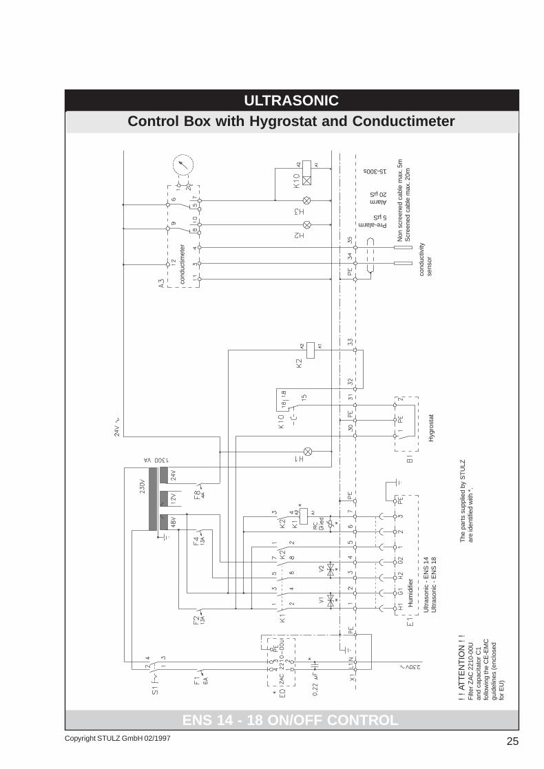
When the control box is wired, the suppressor diodes provided to protect theoscillators have to be connected in parallel with the oscillator boards. For alltypes, the provided contactor for the bath response (level indicator of watertank) has to be additionally used and to be connected with the RC moduleprovided. Other contactors would destroy the float switch.
Incorrect wiring of the control box may cause damage to the humidifier; thecontrol boxes should therefore be wired in accordance with the wiring dia-grams provided.
The parts provided by STULZ are identified by "*" in the wiring diagram.
The regulations of the local electric supply companies have to be observed.
Concerning the CE requirements for the European Community please refer topage 70 - 73. The components mentionned on page 70 - 73 must be insertedin the wiring diagrams of this chapter.

ULTRASONIC
21Copyright STULZ GmbH 02/1997
SET-UP OF ON/OFF CONTROL
Set-up of ON/OFF Control
The most simple mode of control is made by means of a hygrostat whichcompares the room humidity values (actual value) with the value adjusted(setpoint). If the actual value falls below the setpoint, the hygrostat will turnthe humidifier to ON, if the value is higher, the unit is turned off. The controloperation is run with a predetermined switching hysteresis around thesetpoint.
4.1

22 Copyright STULZ GmbH 02/1997
ULTRASONICControl Box with Hygrostat and Conductimeter
Hyg
rost
at
Hum
idifi
er
Ultr
ason
ic -
EN
S 1
200
Ultr
ason
ic -
EN
S 2
400
ENS 1200 - 2400 ON/OFF CONTROL
The
par
ts s
uppl
ied
by S
TU
LZar
e id
entif
ied
with
*.
Non
scr
eene
d ca
ble
max
. 5m
Scr
eene
d ca
ble
max
. 20m
cond
uctiv
ityse
nsor
Pre-alarm5 µS
Alarm20 µS
15-300s
cond
uctim
eter
E71T2.PM5 17.04.97, 16:4222
23Copyright STULZ GmbH 02/1997
ULTRASONICControl Box with Hygrostat and Conductimeter
Hyg
rost
atU
ltras
onic
- E
NS
360
0U
ltras
onic
- E
NS
480
0U
ltras
onic
- E
NS
600
0
ENS 3600 - 6000 ON/OFF CONTROL
Hum
idifi
er
The
par
ts s
uppl
ied
by S
TU
LZar
e id
entif
ied
with
*.
Non
scr
eene
d ca
ble
max
. 5m
Scr
eene
d ca
ble
max
. 20m
cond
uctiv
ityse
nsor
Pre-alarm5 µS
Alarm20 µS
15-300s
cond
uctim
eter
E71T2.PM5 17.04.97, 10:4623

24 Copyright STULZ GmbH 02/1997
ULTRASONICControl Box with Hygrostat and Conductimeter
Hyg
rost
atU
ltras
onic
- E
NS
720
0U
ltras
onic
- E
NS
840
0U
ltras
onic
- E
NS
960
0
ENS 7200 - 9600 ON/OFF CONTROL
Hum
idifi
er
The
par
ts s
uppl
ied
by S
TU
LZar
e id
entif
ied
with
*.
Non
scr
eene
d ca
ble
max
. 5m
Scr
eene
d ca
ble
max
. 20m
cond
uctiv
ityse
nsor
Pre-alarm5 µS
Alarm20 µS
15-300s
cond
uctim
eter
E71T2.PM5 17.04.97, 10:4624
25Copyright STULZ GmbH 02/1997
ULTRASONICControl Box with Hygrostat and Conductimeter
ENS 14 - 18 ON/OFF CONTROL
Hyg
rost
atU
ltras
onic
- E
NS
14
Ultr
ason
ic -
EN
S 1
8
! !
ATT
EN
TIO
N !
!F
ilter
ZA
C 2
210-
00U
and
capa
cita
tor
C1
follo
win
g th
e C
E-E
MC
guid
elin
es (
encl
osed
for
EU
)
Hum
idifi
er
The
par
ts s
uppl
ied
by S
TU
LZar
e id
entif
ied
with
*.
Non
scr
eene
d ca
ble
max
. 5m
Scr
eene
d ca
ble
max
. 20m
cond
uctiv
ityse
nsor
Pre-alarm5 µS
Alarm20 µS
15-300s
cond
uctim
eter
E71T2.PM5 17.04.97, 10:4625

26 Copyright STULZ GmbH 02/1997
ULTRASONICSET-UP OF PROPORTIONALEN CONTROL
4.2 Set-up of Proportional Control
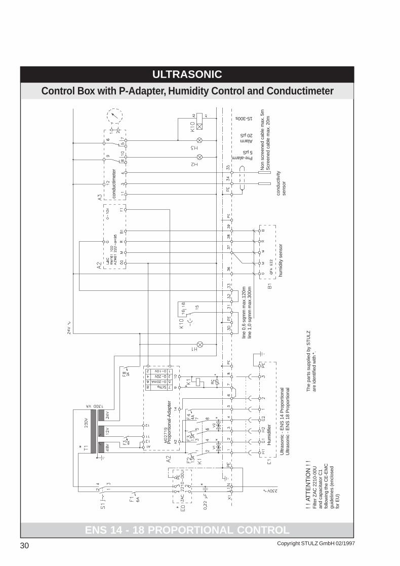
For proportional control, the actual value is compared with the setpointand the humidifier output is adjusted in accordance with the controldifference. Proportional control consists of the humidity sensor, thecontinuous controller and the STULZ proportional adapter, which formsthe interface between the humidifier and the control components.
E71T2.PM5 17.04.97, 10:4626

27Copyright STULZ GmbH 02/1997
ULTRASONICControl Box with P-Adapter, Humidity Control and Conductimeter
hum
idity
sen
sor
Pro
port
iona
l-Ada
pter
line
0,6
sqm
m m
ax.1
20m
line
1,0
sqm
m m
ax.3
00m
ENS 1200 - 2400 PROPORTIONAL CONTROL
Ultr
ason
ic -
EN
S 1
200
Pro
port
iona
lU
ltras
onic
- E
NS
240
0 P
ropo
rtio
nal The
par
ts s
uppl
ied
by S
TU
LZar
e id
entif
ied
with
*.
Non
scr
eene
d ca
ble
max
. 5m
Scr
eene
d ca
ble
max
. 20m
cond
uctiv
ityse
nsor
Pre-alarm5 µS
Alarm20 µS
15-300s
cond
uctim
eter
Hum
idifi
er
E71T2.PM5 17.04.97, 10:4627

28 Copyright STULZ GmbH 02/1997
ULTRASONIC
Control Box with P-Adapter, Humidity Control and Conductimeter
Pro
port
iona
l-Ada
pter
ENS 3600 - 6000 PROPORTIONAL CONTROL
Ultr
ason
ic -
EN
S 3
600
Pro
port
iona
lU
ltras
onic
- E
NS
480
0 P
ropo
rtio
nal
Ultr
ason
ic -
EN
S 6
000
Pro
port
iona
l
hum
idity
sen
sor
line
0,6
sqm
m m
ax.1
20m
line
1,0
sqm
m m
ax.3
00m
The
par
ts s
uppl
ied
by S
TU
LZar
e id
entif
ied
with
*.
Non
scr
eene
d ca
ble
max
. 5m
Scr
eene
d ca
ble
max
. 20m
cond
uctiv
ityse
nsor
Pre-alarm5 µS
Alarm20 µS
15-300s
cond
uctim
eter
Hum
idifi
er
E71T2.PM5 17.04.97, 10:4628

29Copyright STULZ GmbH 02/1997
ULTRASONICControl Box with P-Adapter, Humidity Control and Conductimeter
Pro
port
iona
l-Ada
pter
ENS 7200 - 9600 PROPORTIONAL CONTROL
Ultr
ason
ic -
EN
S 7
200
Pro
port
iona
lU
ltras
onic
- E
NS
840
0 P
ropo
rtio
nal
Ultr
ason
ic -
EN
S 9
600
Pro
port
iona
l
hum
idity
sen
sor
line
0,6
sqm
m m
ax.1
20m
line
1,0
sqm
m m
ax.3
00m
The
par
ts s
uppl
ied
by S
TU
LZar
e id
entif
ied
with
*.
Non
scr
eene
d ca
ble
max
. 5m
Scr
eene
d ca
ble
max
. 20m
cond
uctiv
ityse
nsor
Pre-alarm5 µS
Alarm20 µS
15-300s
cond
uctim
eter
Hum
idifi
er
E71T2.PM5 17.04.97, 10:4629
30 Copyright STULZ GmbH 02/1997
ULTRASONIC
Control Box with P-Adapter, Humidity Control and Conductimeter
ENS 14 - 18 PROPORTIONAL CONTROL
Ultr
ason
ic -
EN
S 1
4 P
ropo
rtio
nal
Ultr
ason
ic -
EN
S 1
8 P
ropo
rtio
nal
Pro
port
iona
l-Ada
pter
line
0,6
sqm
m m
ax.1
20m
line
1,0
sqm
m m
ax.3
00m
The
par
ts s
uppl
ied
by S
TU
LZar
e id
entif
ied
with
*.
Non
scr
eene
d ca
ble
max
. 5m
Scr
eene
d ca
ble
max
. 20m
cond
uctiv
ityse
nsor
Pre-alarm5 µS
Alarm20 µS
15-300s
hum
idity
sen
sor
cond
uctim
eter
Hum
idifi
er
! !
ATT
EN
TIO
N !
!F
ilter
ZA
C 2
210-
00U
and
capa
cita
tor
C1
follo
win
g th
e C
E-E
MC
guid
elin
es (
encl
osed
for
EU
)
E71T2.PM5 17.04.97, 10:4630

ULTRASONIC
31Copyright STULZ GmbH 02/1997
Function of Proportional Adapter
1. GeneralThe proportional adapter M 02719 (P- Adapter is a power device thatchanges its operating time proportionally dependent on four differentcontroller inputs.
2. FunctionWhen the threshold value of 1.2 VDC (or 1.2 mADC) is exceeded, the relayat terminal 13, 14 (refer to wiring plan, propartional adapter M02719)switches the water intake valve to ON, provided that the supply voltage of12 VAC is fed to terminals 11 and 12. If bath response (water tank level) of48 VAC/50 Hz is given to terminal 9 and 10 of the proportional adapter, thegreen LED illuminates. At the same time, the solid-state relay startsoperating with an operating time of 10%. This is indicated by flashing of thered LED.
With the DIP switches installed on the printed board of the proportionaladpter, the operating cycles may be adjusted between 1 sec. and 3 sec.
Oper. Cycles Position of DIP switches Switch(Second (s)) position
1 1=OFF 2=OFF 3=ON 4=ON UP=OFF 2 1=ON 2=OFF 3=ON 4=ON DOWN=ON 3 1=ON 2=ON 3=OFF 4=OFF
An increasing value at the inlet of the proportional adapter causes anextension of the operating time of the outlet. All inlets are uncoupled.
When the determined maximum value is achieved at one of the inlets, theoperating time of 100% has been reached.
FUNCTION OF PROPORTIONAL ADAPTER
4.3

ULTRASONIC
32Copyright STULZ GmbH 02/1997
3. Technical Data
Elektric power consumption: 1 WPower loss at 100%operating factor: 21 W (at 21 A eff)On-load voltage: 24 - 280 V effPeak off-state voltage: 600 VLeak current (at 280 V eff): 8 - 15 mA effTurn on/off procedure: No voltage releaseElectric strength ofPotential separation: min. 2500 V effInsulation resistance: 50 MOhmOperating temperature: 0 ... + 80°CMax. cooling body temperature: horizontal 63°C
vertical 55°C
FUNCTION OF PROPORTIONAL ADAPTER

ULTRASONIC
33Copyright STULZ GmbH 02/1997
Terminal Configuration
Terminal 1 +0.... 10 V DC reverse battery protected con-Terminal 2 GND troller input Rin=20 kOhmTerminal 3 +0....20 V DC reverse battery protected con-Terminal 4 GND troller input Rin=40 kOhmTerminal 5 +0....20 mA DC reverse battery protected con-Terminal 6 GND troller input Rin=1 kOhmTerminal 7 0.....20 (30) V AC isolated controller inputTerminal 8 GND Rin>150 kOhm,
via TP1*adjustable to 20/30 V
Terminal 9 Bath response humidifier responseTerminal10 Bath response release by water level
48VAC/50HzTerminal 11 Supply voltage 12 V AC supply voltageTerminal 12 Supply voltage of P-adapter ~1WTerminal 13 Input 48 VAC no voltage relay contractTerminal 14 Output for water intake valveTerminal A1 Input 48 VAC No voltage electronic noTerminal A2 Output voltage a.c. zero voltage switch
load 24...280 V AC/50 Hz21 A steady load
40 A short-time load
*Adjustment TP 1 Left-hand stop: 0......30 V
Right-hand stop: 0......20 V
TP1 Powerelektronics
Terminals
FUNCTION OF PROPORTIONAL ADAPTER
}}
}
}
}}
}
}

ULTRASONIC
34Copyright STULZ GmbH 02/1997
Connecting Lines between Humidifiers and Control System
Connecting Lines between Humidifiers and Control System
1. ON/OFF Control ENS 1200 to 9000Proportional Control ENS 1200 to ENS 9600
The line, length 4 m and preset, is connected to the control box according tothe identifications given. In case the connecting line is extended, the dimen-sioning (refer to 5.) has to be taken into consideration.
2. ON/OFF Control ENS14 and ENS18Proportional Control ENS 14 and ENS 18
The cables, length 2 m and preset, provided with plugs are plugged intothe sockets provided at the units and are screwed down.In case the connecting line is extended, the dimensioning (refer to 4.) has tobe taken in consideration.
3. Preset Line ENS 14 and ENS18
4.4
ULTRASONIC
35Copyright STULZ GmbH 02/1997
Connecting Lines between Humidifiers and Control System
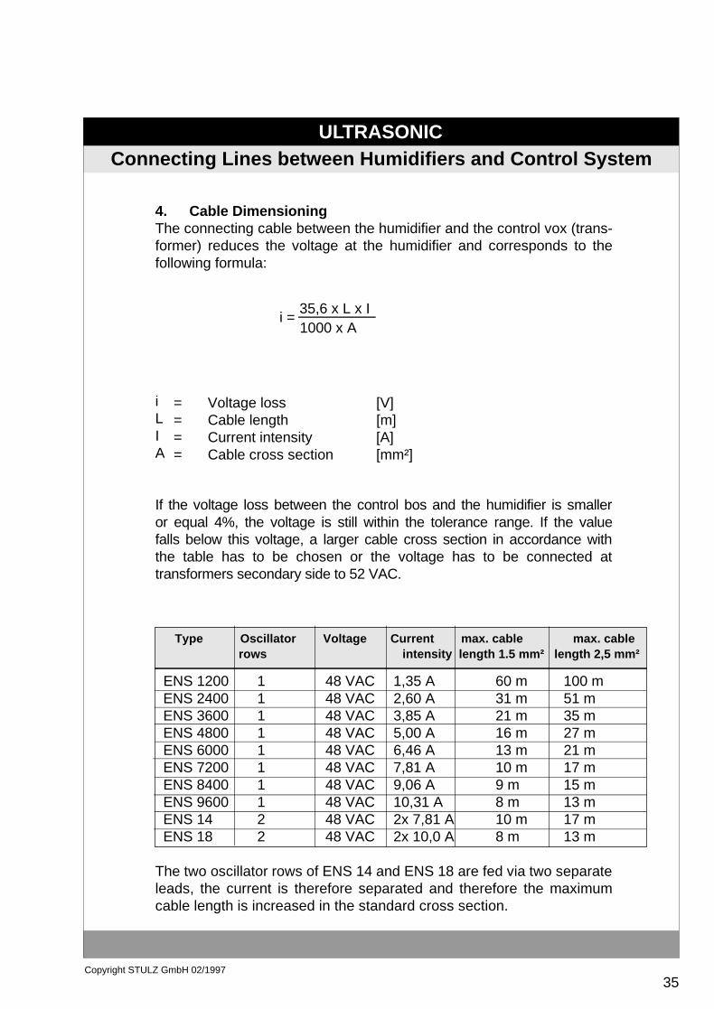
4. Cable DimensioningThe connecting cable between the humidifier and the control vox (trans-former) reduces the voltage at the humidifier and corresponds to thefollowing formula:
iLIA
If the voltage loss between the control bos and the humidifier is smalleror equal 4%, the voltage is still within the tolerance range. If the valuefalls below this voltage, a larger cable cross section in accordance withthe table has to be chosen or the voltage has to be connected attransformers secondary side to 52 VAC.
ENS 1200 1 48 VAC 1,35 A 60 m 100 m ENS 2400 1 48 VAC 2,60 A 31 m 51 m ENS 3600 1 48 VAC 3,85 A 21 m 35 m ENS 4800 1 48 VAC 5,00 A 16 m 27 m ENS 6000 1 48 VAC 6,46 A 13 m 21 m ENS 7200 1 48 VAC 7,81 A 10 m 17 m ENS 8400 1 48 VAC 9,06 A 9 m 15 m ENS 9600 1 48 VAC 10,31 A 8 m 13 m ENS 14 2 48 VAC 2x 7,81 A 10 m 17 m ENS 18 2 48 VAC 2x 10,0 A 8 m 13 m
The two oscillator rows of ENS 14 and ENS 18 are fed via two separateleads, the current is therefore separated and therefore the maximumcable length is increased in the standard cross section.
Type Oscillator Voltage Current max. cable max. cable rows intensity length 1.5 mm² length 2,5 mm²
i =1000 x A35,6 x L x I
= Voltage loss [V]= Cable length [m]= Current intensity [A]= Cable cross section [mm²]
ULTRASONIC
36Copyright STULZ GmbH 02/1997
ELECTROTECHNICAL INFORMATION ENS 1200-9600
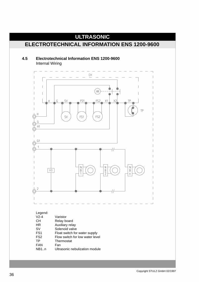
4.5 Electrotechnical Information ENS 1200-9600Internal Wiring
Legend:V2-4 VaristorCH Relay boardHR Auxiliary relaySV Solenoid valveFS1 Float switch for water supplyFS2 Flow switch for low water levelTP ThermostatFAN FanNB1..n Ultrasonic nebulization module

ULTRASONIC
37Copyright STULZ GmbH 02/1997
ELECTROTECHNICAL INFORMATION ENS 14-18
Electrotechnical Information ENS 14-18Internal Wiring
4.6
Legend::CH Relay boardLWU VaristorSV Solenoid valveFS1 Float switch for water supplyFS2 Float switch for low water levelTP Thermal protectorNB1..n Ultrasonic nebulization moduleWS Water sensor
ULTRASONIC
38Copyright STULZ GmbH 02/1997
ASSEMBLY, SET-UP AND LIMITS OF APPLICATION
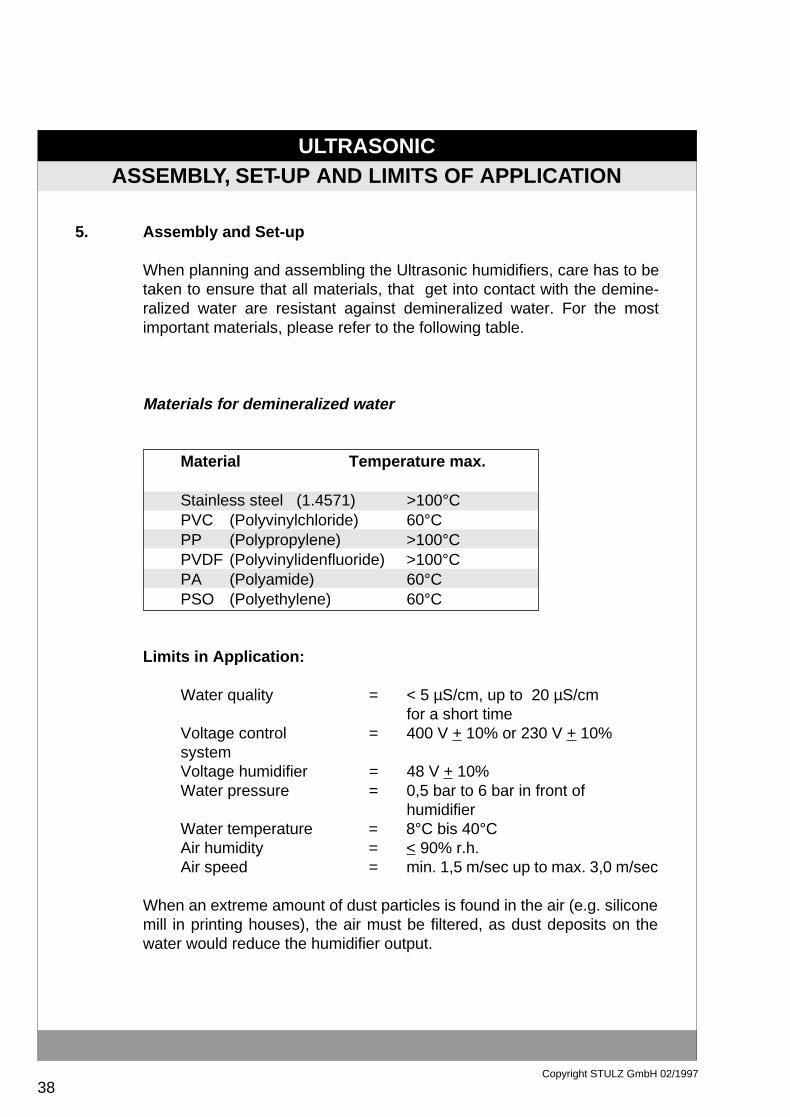
Assembly and Set-up
When planning and assembling the Ultrasonic humidifiers, care has to betaken to ensure that all materials, that get into contact with the demine-ralized water are resistant against demineralized water. For the mostimportant materials, please refer to the following table.
Materials for demineralized water
Material Temperature max.
Stainless steel (1.4571) >100°CPVC (Polyvinylchloride) 60°CPP (Polypropylene) >100°CPVDF (Polyvinylidenfluoride) >100°CPA (Polyamide) 60°CPSO (Polyethylene) 60°C
Limits in Application:
Water quality = < 5 µS/cm, up to 20 µS/cmfor a short time
Voltage control = 400 V + 10% or 230 V + 10%systemVoltage humidifier = 48 V + 10%Water pressure = 0,5 bar to 6 bar in front of
humidifierWater temperature = 8°C bis 40°CAir humidity = < 90% r.h.Air speed = min. 1,5 m/sec up to max. 3,0 m/sec
When an extreme amount of dust particles is found in the air (e.g. siliconemill in printing houses), the air must be filtered, as dust deposits on thewater would reduce the humidifier output.
5.

ULTRASONIC
39Copyright STULZ GmbH 02/1997
ASSEMBLY ENS SERIES
Assembly ENS Series
The humidifier can be installed in a compact air conditioning unit, aventilation or aereation system or into an air duct. In any case, the unitshould be installed such that it is easily accessible for reapir and service.A drain pan made from stainless steel (1.4571) has to be provided. Thelength of the pan should correspond to the humidifier path. (refer to 3.00).
Installation Scheme
5.1
Legend for Installation Scheme
1. Control box2. to be provided by customer3. Connection 3/4" male thread (gasket)
provide passage pipe interruptor4. Hand valve5. Stainless steel pipe φ 6 mm (1.4571)

ULTRASONIC
40Copyright STULZ GmbH 02/1997
ASSEMBLY ENS SERIES
6. Ultrasonic humidification7. Measuring electrode8. 1 or 2 demineralizers or reversal osmosis
incl. 1 demineralizer9. Safety overflow10. Water outlet11. Provide drain12. Stainless steel drain pan (1.4571) or PVC
Please observe the following instructions upon assembly of thehumidifier:
a. Install humidifier in exactly horizontal position.
b. The identification on the casing shows that direction of air flow mustcorrespond to actual direction of air flow.
c. Sufficient clearance to be provided above humidifier to enable removalof the mist collector for inspection purposes and cleaning of the watertanks.
d. The ENS humidifier must only be attached at one side to ensure thattemperature changes will not set the humidifier casing under mechanicalstress. Attachment of the humidifier at both sides may cause damage tothe humidifier!

ULTRASONIC
41Copyright STULZ GmbH 02/1997
ASSEMBLY ENS SERIES
Water Supply Lines
1) Only use fully demineralized water <5µS/cm together with the humidifier.Install one check valve in each humidifier. Admission pressure 0.5 to 5 bar.
2) Perform connection between demineralization unit and the humidifier bymeans of a material that is resistant to fully demineralized water (e.g. PE orstainless steel (1.4571).
3) Swarf and dirt accumulation must not get into the water lines. Clean all linesbefore connecting them to the humidifier. Dependent on the safety risk, eitheruse pressure tubing or stainless steel pipe to make the water lines.
4) Install the safety overflow. Under standard operating conditions, no water willflow out of the overflow pipe.
Hydraulic Schematic Diagram

ULTRASONIC
42Copyright STULZ GmbH 02/1997
ASSEMBLY ENS SERIES
Waterside connections at humidifiers type ENS. For position of the connections and otherunit dimensions please refer to point 2.2.
Water Suppl y Line
Overflo w
ULTRASONIC
43Copyright STULZ GmbH 02/1997
ASSEMBLY ENS SERIES
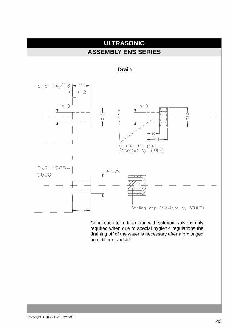
Drain
Connection to a drain pipe with solenoid valve is onlyrequired when due to special hygienic regulations thedraining off of the water is necessary after a prolongedhumidifier standstill.
ULTRASONIC
44Copyright STULZ GmbH 02/1997
PIPING EXAMPLE
De-minera
lizer1
De-minera-
lizer2
ENS Humidifier
ENS Humidifier
ENS Humidifier
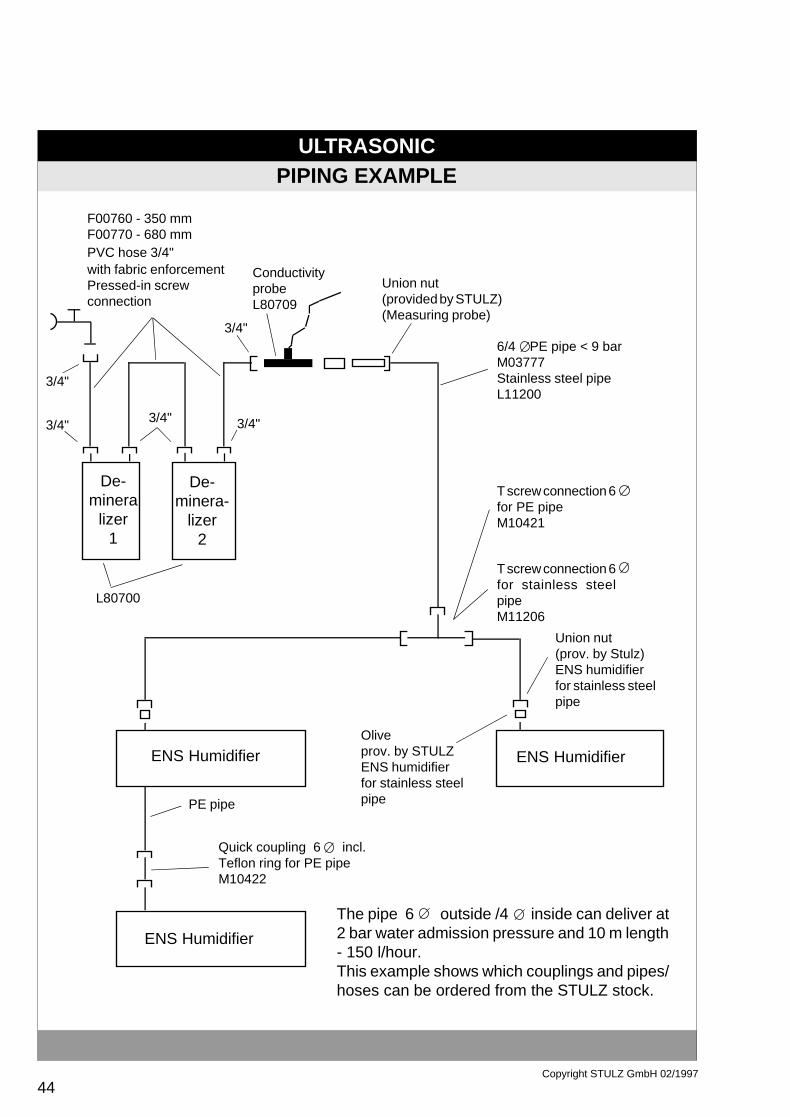
F00760 - 350 mmF00770 - 680 mmPVC hose 3/4"with fabric enforcementPressed-in screwconnection
T screw connection 6for stainless steelpipeM11206
T screw connection 6for PE pipeM10421
6/4 PE pipe < 9 barM03777Stainless steel pipeL11200
Union nut(prov. by Stulz)ENS humidifierfor stainless steelpipe
Oliveprov. by STULZENS humidifierfor stainless steelpipePE pipe
Quick coupling 6 incl.Teflon ring for PE pipeM10422
L80700
3/4"
3/4"
3/4"
3/4"3/4"
The pipe 6 outside /4 inside can deliver at2 bar water admission pressure and 10 m length- 150 l/hour.This example shows which couplings and pipes/hoses can be ordered from the STULZ stock.
Union nut(provided by STULZ)(Measuring probe)
ConductivityprobeL80709

ULTRASONIC
45Copyright STULZ GmbH 02/1997
INSTALLATION EXAMPLES ENS HUMIDIFIERS

ULTRASONIC
46Copyright STULZ GmbH 02/1997
ASSEMBLY ENS SERIES
Installation into a Duct
Legend
1. Duct piece of stainless steel2. Water drain (provide syphon)3. In case of non-laminar flow, install a perforated plate in direction of
airflow in front of the humidifierRequirement: open cross section 60%.
4. Direct connection of safety overflow
To obtain shortest possible humidifier paths it is very important todistribute the mist as evenly as possible across the total duct or unit crosssection and to keep air speed within the range of 1.5 to 3 m/sec. In thefollowing, some installations are shown, which are possible by means ofbuffle plates or perforated plates.

ULTRASONIC
47Copyright STULZ GmbH 02/1997
ASSEMBLY ENS SERIES
Ultrasonic humidifiers of ENS series can be used for laminar flows at airspeeds between 1.5 and 3 m/s. Should this air speed be exceeded, aperforated plate has to be installed in front of the air inlet of the humidifier(illustration no. 1). The perforated plates reduce the free cross section bymore than 60% and therefore reduce the air speed through the humidifierin a very efficient way. For installation of the perforated plate, an anglesection (illustration no. 2 and 3) is fastened to humidifier's assembly screwconnection, where the perforated plate is then fixed to.

ULTRASONIC
48Copyright STULZ GmbH 02/1997
ASSEMBLY ENS SERIES
Illustration no. 1
Perforated plate Ultrasonic ENS
Article-no. Humidifier type A [mm] B [mm)
M03191 ENS 1200 185 136M03190 ENS 2400 185 255M03189 ENS 3600 185 375M10431 ENS 4800 185 495M03188 ENS 6000 185 615M03187 ENS 7200 185 735M03186 ENS 8400 185 855M03184 ENS 9600 185 975
M10432 ENS 14 165 705M10433 ENS 18 165 870
Material: Aluminium perforated plateA FRE approx.. 38 %d hole 3.2 mmd= 1 mm
ULTRASONIC
49Copyright STULZ GmbH 02/1997
ASSEMBLY ENS SERIES
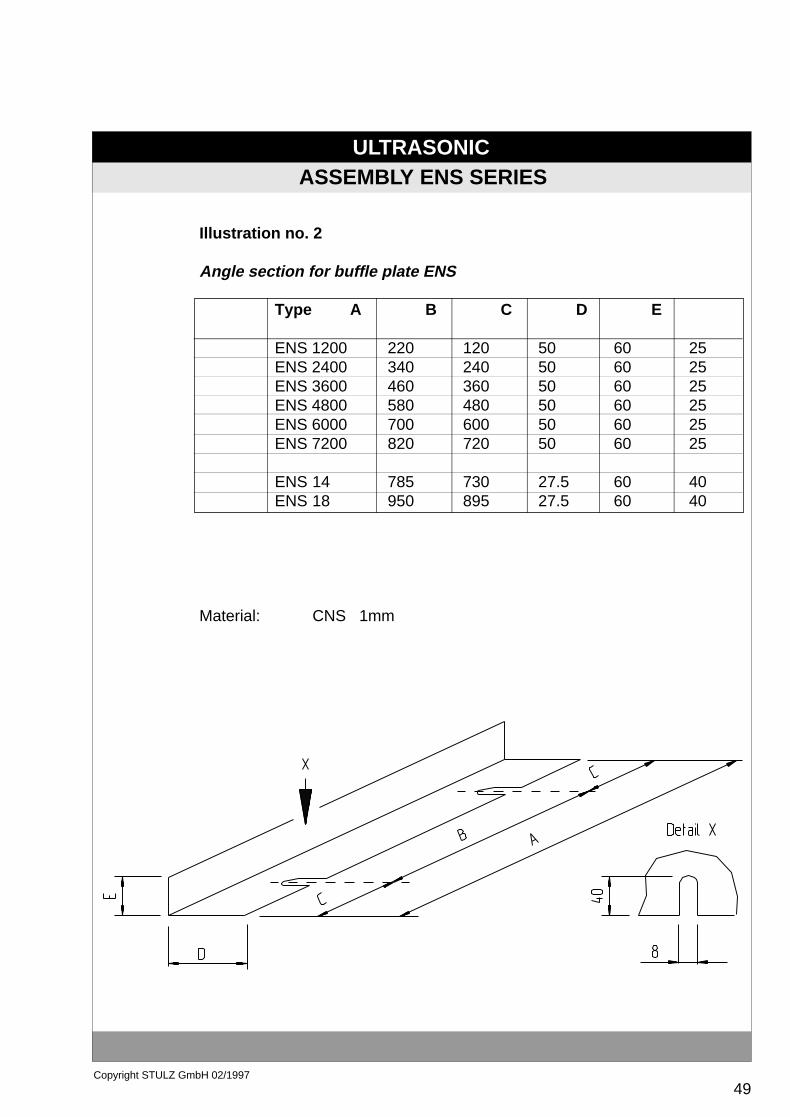
Illustration no. 2
Angle section for buffle plate ENS
Type A B C D E
ENS 1200 220 120 50 60 25ENS 2400 340 240 50 60 25ENS 3600 460 360 50 60 25ENS 4800 580 480 50 60 25ENS 6000 700 600 50 60 25ENS 7200 820 720 50 60 25
ENS 14 785 730 27.5 60 40ENS 18 950 895 27.5 60 40
Material: CNS 1mm

ULTRASONIC
50Copyright STULZ GmbH 02/1997
ASSEMBLY ENS SERIES
Illustration no. 3
Angle section for buffle plate ENS
Type A B1 B2 C D E
ENS 8400 940 480 360 50 60 25ENS 9600 1060 480 480 50 60 25
Material: CNS 1mm

ULTRASONIC
51Copyright STULZ GmbH 02/1997
ASSEMBLY ENS SERIES
Buffle plates (illustrations 4, 5 and 6) are used to reverse the air flow,entering the humidifier from above, to horizontal flow and to guide itthrough the humidifier. The buffle plates are fixed to an U-profile (illu-stration no. 7) which is mounted below the humidifier.

ULTRASONIC
52Copyright STULZ GmbH 02/1997
ASSEMBLY ENS SERIES
Illustration no. 4
Buffle plate for ENS
Type: ENS 1200 - 3600Material: CNS 1mm

ULTRASONIC
53Copyright STULZ GmbH 02/1997
ASSEMBLY ENS SERIES
Drawing no. 5
Buffle plate for ENS
Type: ENS 4800 - 7200Material: CNS 1mm

ULTRASONIC
54Copyright STULZ GmbH 02/1997
ASSEMBLY ENS SERIES
Illustration no. 6
Buffle plate for ENS
Type: ENS 8400 + 9600Material: CNS 1mm

ULTRASONIC
55Copyright STULZ GmbH 02/1997
Illustration no. 7
U- profile for buffle plate ENS
Type A B C D
ENS 1200 - 3600 40 550 165 10ENS 4800 - 7200 40 890 165 10ENS 8400 + 9600 40 1150 165 10
Material: CNS 1mm
ASSEMBLY ENS SERIES
ULTRASONIC
56Copyright STULZ GmbH 02/1997
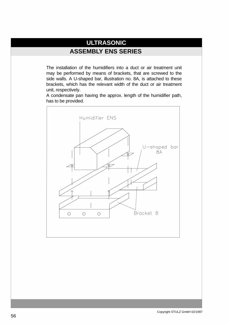
ASSEMBLY ENS SERIES
The installation of the humidifiers into a duct or air treatment unitmay be performed by means of brackets, that are screwed to theside walls. A U-shaped bar, illustration no. 8A, is attached to thesebrackets, which has the relevant width of the duct or air treatmentunit, respectively.A condensate pan having the approx. length of the humidifier path,has to be provided.

ULTRASONIC
57Copyright STULZ GmbH 02/1997
Illustration no. 8: Assembly design ENS
Brackets
Article-No. Type A * B * * inside dim.
M03180 ENS 1200 - 9600 173 25M03183 ENS 14 +18 273 40
Material: V2A 1mm
Illustration no. 8a:U-shaped bar
Type A * B * C *Inside dim
ENS 1200 - 9600 170 25ENS 14 +18 270 40
Material: V2A 1mm
ASSEMBLY ENS SERIES
ULTRASONIC
58Copyright STULZ GmbH 02/1997
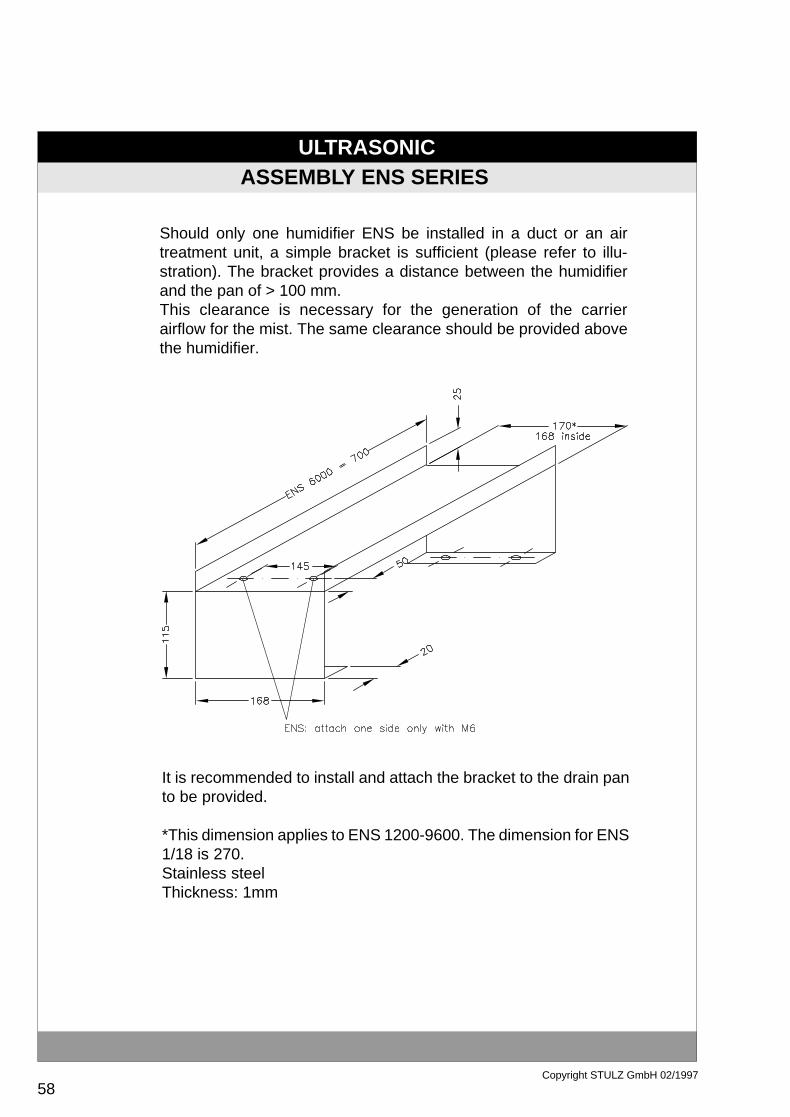
ASSEMBLY ENS SERIES
Should only one humidifier ENS be installed in a duct or an airtreatment unit, a simple bracket is sufficient (please refer to illu-stration). The bracket provides a distance between the humidifierand the pan of > 100 mm.This clearance is necessary for the generation of the carrierairflow for the mist. The same clearance should be provided abovethe humidifier.
It is recommended to install and attach the bracket to the drain panto be provided.
*This dimension applies to ENS 1200-9600. The dimension for ENS1/18 is 270.Stainless steelThickness: 1mm

ULTRASONIC
59Copyright STULZ GmbH 02/1997
ASSEMBLY ENS SERIES
If several huidifiers ENS are to be installed in a duct or an airtreatment unit, they have to be distributed across the duct crosssection, in order to achieve a constant distribution of humidity inthe airflow.
An appropriate stand to accomodate the humidifier in the air treat-ment unit is shown in the illustration.
ULTRASONIC
60Copyright STULZ GmbH 02/1997
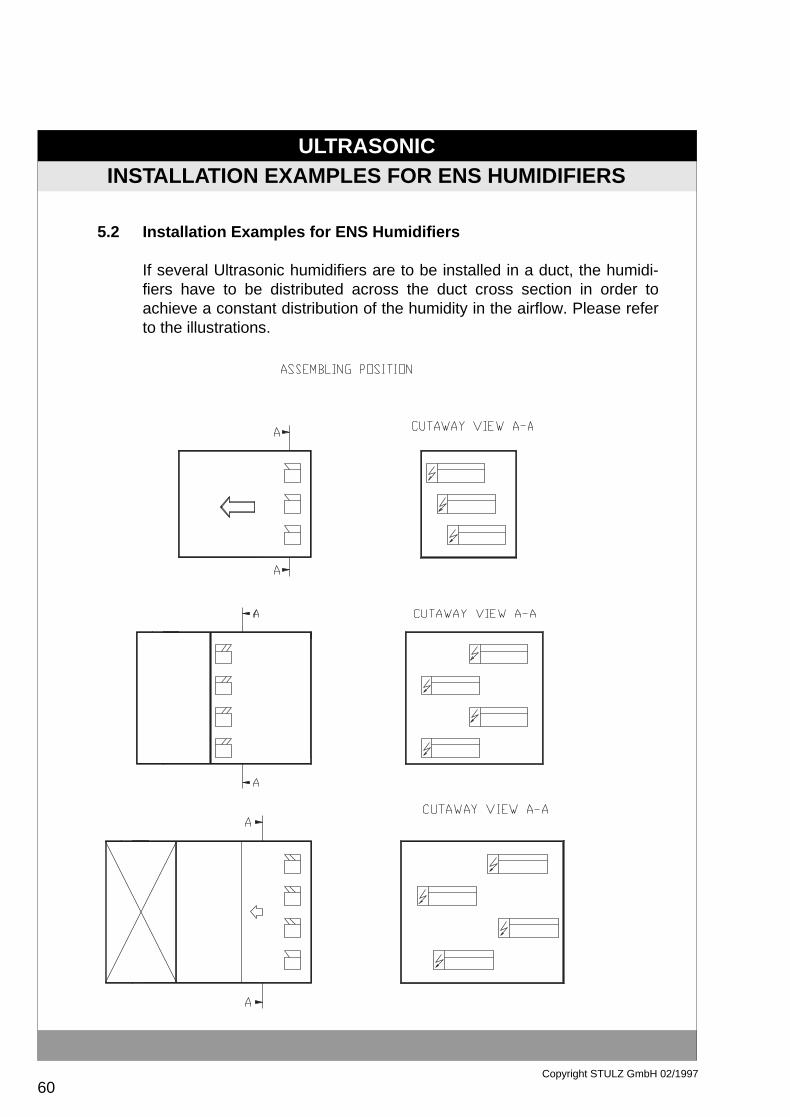
Installation Examples for ENS Humidifiers
If several Ultrasonic humidifiers are to be installed in a duct, the humidi-fiers have to be distributed across the duct cross section in order toachieve a constant distribution of the humidity in the airflow. Please referto the illustrations.
INSTALLATION EXAMPLES FOR ENS HUMIDIFIERS
5.2

ULTRASONIC
61Copyright STULZ GmbH 02/1997
INSTALLATION EXAMPLES FOR ENS HUMIDIFIERS
Install the humidifiers at the suction side.
Use an air rectifier in the airflow in front of the humidifier; heat exchangersalso fulfil the rectification function.
During heating process, the air temperature at the humidifier casing mustnot exceed 40°C.
The distance to the next object behind the humidifier in airflow directionshould be larger than the humidifier path.
Provide a stainless steel pan corresponding to the lengthof the humidifierpath. The pan must be fitted with a drain, connected to a syphon. The heightof the syphon is dependent on the differential pressure (environment/suction side in the unit).
To ensure that a sufficient carrier airflow is available for the aerosols thatare getting out the humidifier, a distance of > 10 cm to the pan has to beprovided for the lowest humidifier. The same is applicable on top of thehumidifier and at the sides.
1.
2.
3.
4.
5.
6.
ULTRASONIC
62Copyright STULZ GmbH 02/1997
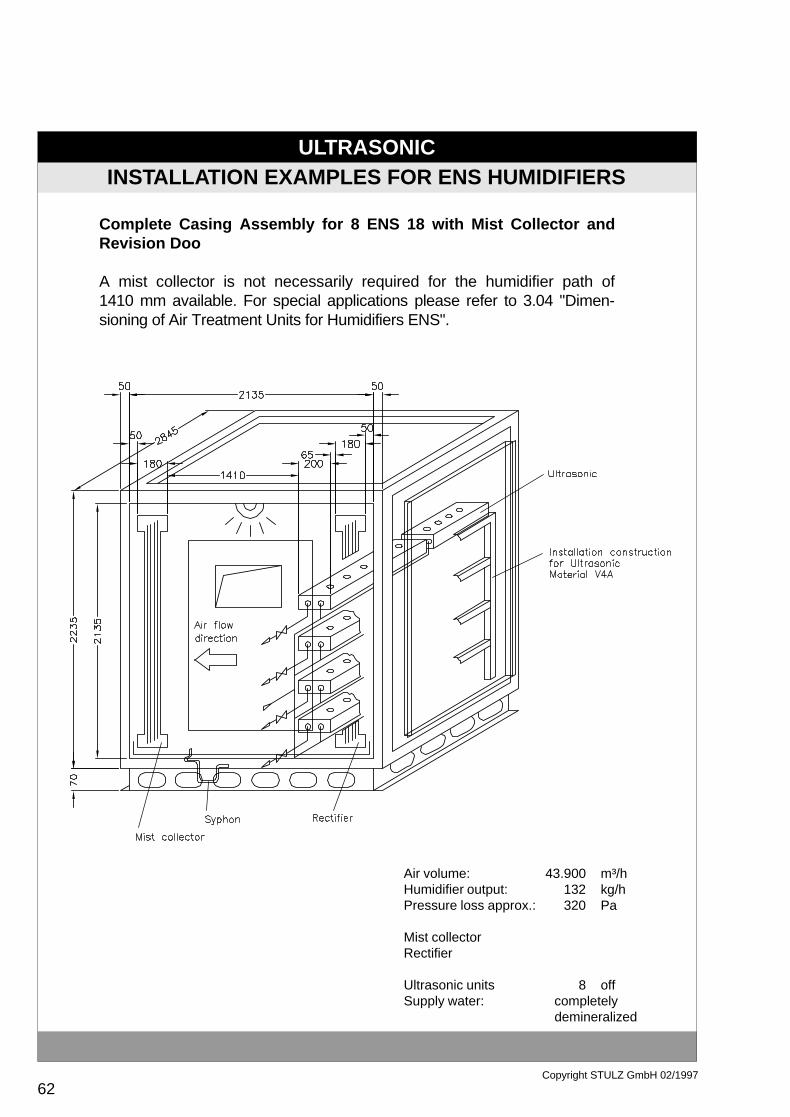
Air volume:Humidifier output:Pressure loss approx.:
Mist collectorRectifier
Ultrasonic unitsSupply water: completely
demineralized
INSTALLATION EXAMPLES FOR ENS HUMIDIFIERS
Complete Casing Assembly for 8 ENS 18 with Mist Collector andRevision Doo
A mist collector is not necessarily required for the humidifier path of1410 mm available. For special applications please refer to 3.04 "Dimen-sioning of Air Treatment Units for Humidifiers ENS".
43.900132320
8
m³/hkg/hPa
off

ULTRASONIC
63Copyright STULZ GmbH 02/1997
START-UP HUMIDIFIERS TYPE ENS
Start-up of Humidifiers Type ENS
Preparation for initial operation
a. Install the humidifier exactly in horizontal position and place humidifierin direction of airflow.
b. Ensure that all line connections are made correctly, firmly and safe.
c. Electric power supply is rated at 230/48 volt and is interlocked with the fan.
d. Assemble and attach all other components in correct and safe manner.
e. Make sure that the humidifier is supplied with electric current and fullydemineralized water.
f. To protect the water supply line against a too low pressure, a presso-statis interlocked with the humidifier.
Precautions for a longer standstill
1) If the humidifier is not used for a longer period of time, the water mustbe drained off.
2) Close the water supply check valve.
3) Switch off the main switch at the control box.
5.3
ULTRASONIC
64Copyright STULZ GmbH 02/1997
START-UP OF ENS HUMIDIFIERS
Before attempting to start the humidifier after a longer standstill,check the following points:
a. Check whether the humidifier casing is in correct position and correctlyinstalled, and whether humidifier is in good operating condition.
b. Ensure that the mains and water supply to the humidifier has beenconnected.
* Never switch in the main switch when the humidifier is still positioned onits side or stored topfirst.
*Never operate the humidifier for a prolonged period of time without airsupply.
Humidifier operation
1) Open water valve.
2) Set the hygrostat, i.e. the humidity control, to the desired air humiditylevel.
3) If humidification is demanded and the air conditioning unit is already setto operation, water is automatically filled in up to the necessary level andatomization is started.
4) The mist then generated is blown into the ambient air via the airflow ofthe air conditioning unit and the room is humidified.
5) After that, the water level in the tank is kept to a constant level and airhumidity is maintained at a preset level.
6) Should the water level in the tank fall belwo the safety level duringoperation, operation of the humidifier is stopped by means of the floatswitch.
ULTRASONIC
65Copyright STULZ GmbH 02/1997
PRECAUTIONS FOR OPERATION OF HUMIDIFIERS TYPE ENS
Precautions for Operation of Humidifiers Type ENS
1) Install the humidifier in horizontal position and ensure that the gene-rated mist will be absorbed in an efficient manner by the airflow blown outby the fan of the air conditioning unit. Air speed should be 1.5 to 3.0 m/s.Carefully choose the location of the humidifier in those cases, where aspecial air conditioning unit is used, such as e.g. a compact air conditioningunit, that takes in the air through the humidifier.
2) Current supply should be dimensioned as to ensure that the humidi-fier will be supplied with power current only if the fan of the air conditioningunit is set to operation.
3) A hygrostat or humidity sensor should be activated if the air humidityfalls below the setpoint.
4) Should more than one humidifier be controlled by one hygrostat only,multiplication should be provided by means of several relays.
5) The water used must be fully demineralized. Install a valve in thesupply line for maintenance and control purposes.
6) If the humidifier is intended for installation in air ducts, the airflow rateshould be between 1.5 and 3 m/s; additionally, a stainless steel drain pan(1.4571) has to be provided.
7) Should the air conditioned room be supplied at the same time withhumidity during the cooling procedure, install the humidifier behind thecooling coil in order to prevent any loss in the humidifier output.
8) Should the humidifier be operated in an area where temperature mayall below the freezing point (0°C), insulate and protect the water supplylines and the water tank against frost damage.
5.4
ULTRASONIC
66Copyright STULZ GmbH 02/1997
PRECAUTIONS FOR OPERATION OF HUMIDIFIERS TYPE ENS
9) Observe local requirements and regulations for water supply con-nection.
10) Provide sufficient clearance between the humidifier and the compo-nent parts, which are connected in series, as e.g. the fan, in order toensure the dissolution of the aerosols and to avoid the generation ofcondensates.
11) It is recommended to use maximum sensors in the intke air for con-tinuous and multistage control.
12) For ON/OFF control with one humidifier, a maximum hygrostat canalso be installed in the intake air.
13) Take care to ensure that the water valve is kept open during thehumidification process.
14) Should malfunctions occurr try to eliminate them with the help of thetrouble shooting table.
ULTRASONIC
67Copyright STULZ GmbH 02/1997
Data sheet safety transformers6.1
DATA SHEET SAFETY TRANSFORMERS
ULTRASONIC
68Copyright STULZ GmbH 02/1997
INFORMATION CONCERNING THE CONDUCTIMETER
6.2 Information concerning the Conductimeter
The conductimeter measures and controls the conductivity of the deminera-lized water in µS/cm.
When a measured value of 5 µS/cm is detected, the floating contact for thepre-alarm is activated. The contact is closed via terminals X1.9 and X1.10and opened via terminals X1.9 and X1.8.
When a measured value of 20µS/cm is detected, the floating contact for thealarm indication is activated. The contact is closed via terminals X1.6 andX1.7 and opened via contacts X1.6 and X1.7.
Terminals X1.1 and 1.2 are provided for connection of an indicating instru-ment. Output voltage is rated at 0-1 volt, which corresponds to a measuringrange of 0-50 µS/cm.The conductivity cannot be measured by means of a multimeter.
A potentiometer is provided for final adjustment 0-1 volt. When the printedboard is tested, an adjustment can be made with the connection of resistors.The individual resistances mentioned in the following and connected insteadof the electrode, are intended to simulate :
500 kOhm = 1 µS/cm100 kOhm = 5 µS/cm 50 kOhm = 10 µS/cm 25 kOhm = 20 µS/cm 10 kOhm = 50 µS/cm
The electrode itself can only be checked by comparison measurement.
ULTRASONIC
69Copyright STULZ GmbH 02/1997
INFORMATION CONCERNING THE CONDUCTIMETER
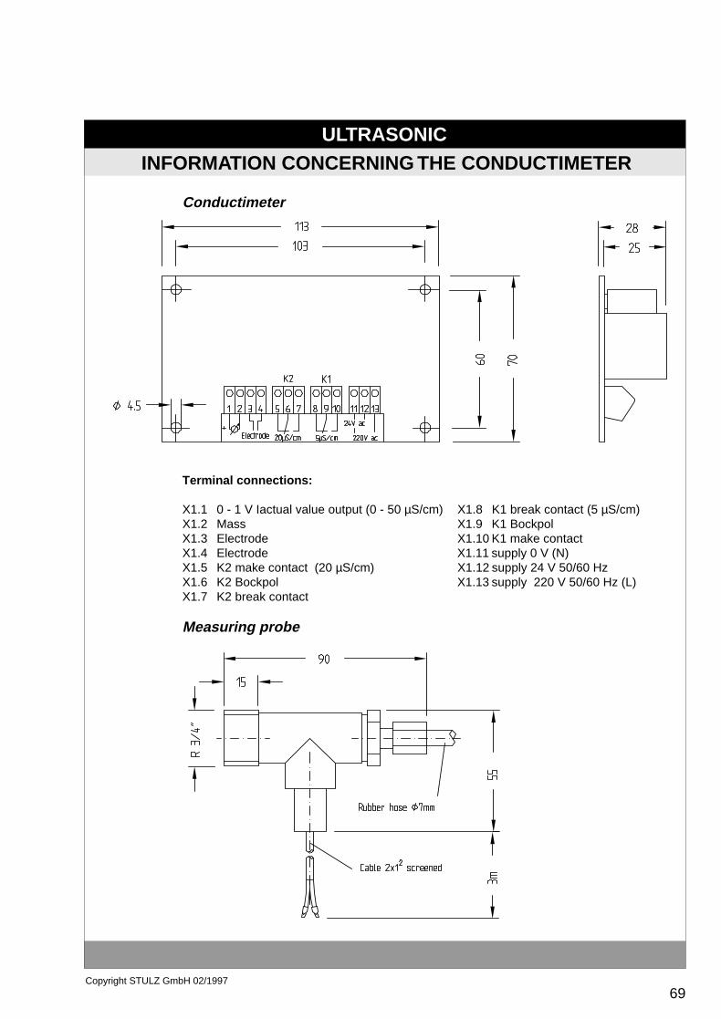
Conductimeter
Terminal connections:
X1.1 0 - 1 V Iactual value output (0 - 50 µS/cm) X1.8 K1 break contact (5 µS/cm)X1.2 Mass X1.9 K1 BockpolX1.3 Electrode X1.10 K1 make contactX1.4 Electrode X1.11 supply 0 V (N)X1.5 K2 make contact (20 µS/cm) X1.12 supply 24 V 50/60 HzX1.6 K2 Bockpol X1.13 supply 220 V 50/60 Hz (L)X1.7 K2 break contact
Measuring probe

70 Copyright STULZ GmbH 02/1997
ULTRASONIC
48 V
ULTRASONIC
0,22µF
0,22µF
230 V Power Supply
Transformer orMUS/SUS
ENS 1200 -
ENS 9600
7.1 Information about the EMC law according to CE-guidelines
On 1st January 1996 the EMC law (Electromagnetic Consistency) came into force for theEuropean Community. The EMC law has special requirements regarding radiation noise,conducted noise, surge immunity and harmonic oscillations. To keep to the regulations inthe industrial area (class A) concerning ultrasonic humidifiers, a power supply filter and/ora condenser - depending on the type of humidifier - has to be connected to the primary ofthe transformer. (From now on the relevant parts will be supplied loose with the delivery.This applies for deliveries within the European Community.). This simple modification isonly necessary for new installations. A retrofit of existing installations is not necessary.
CE - Declaration of Conf ormity
When the following interference suppressing methods are carried out, all STULZ Ultrasonichumidifiers essentially meet the EC-guideline 89/336/EEC, as well as the regulations ofthe harmonized norms EN 55011, EN 60555 and EN 50082-2.
If the units are used wrongly and/or the technical manual and the measures which aredescribed here are not followed, this declaration becomes invalid.
Interf erence Suppressing Method ENS 1200 to ENS 9600:
To fulfil the EMC requirements, two condensers (class Y) 0,22 µF (part no.: M25114) haveto be connected on the primary of the transformer (see diagram below).
CE - EMC law
E71T5.PM5 17.04.97, 14:4070

71Copyright STULZ GmbH 02/1997
ULTRASONIC
It is also necessary to install a shielded cable between the ENS 14/18 and the MUS/SUSor transformer.
48 VENS 14 -
ENS 18
ULTRASONIC Transformer orMUS/SUS
Interf erence Suppressing Method ENS 14 and ENS 18:
To fulfil the EMC requirements, a filter type ZAC 2210-00U (part no.: M25121) or equivalenthas to be connected on the primary of the transformer. In addition a condenser 0,22 µF(part no.: M25114) has to be connected parallel to the filter induct (see diagram).
230 V Power Supply0,22µF
Filter
ZAC2210-00U
4 1
3 2
The follo wing applies f or all Ultrasonic types:
Hamburg, 16.04.1996
WARNING
The Ultrasonic humidifier is an installation class A. This installation can cause radio interferences inresidential areas; in this case the user can be asked to take appropriate measures on his own account.
E71T5.PM5 17.04.97, 14:4071