Ultrasonic Degassing of Aluminium Alloys: Basic Studies ... · Ultrasonic Degassing of Aluminium...
14
Ultrasonic Degassing of Aluminium Alloys: Basic Studies and Practical Implementation Dmitry Eskin 1,2 , Noe Alba-Baena 3 , Thomas Pabel 4 , Manel da Silva 5,6 1 Brunel University, BCAST, Uxbridge, UB8 3PH, U.K. 2 Tomsk State University, Tomsk, 634050 Russia 3 Universidad Autónoma de Ciudad Juárez, Ciudad Juárez, C.P. 32310, Mexico 4 Austrian Foundry Research Institute (ÖGI), 8700 Leoben, Austria 5 ASCAMM Technology Centre, 08290 Cerdanyola del Vallès, Barcelona, Spain 6 Universitat Autònoma de Barcelona, 08193 Cerdanyola del Vallès, Barcelona, Spain Corresponding author: [email protected] Keywords: ultrasound; degassing; aluminium; hydrogen; porosity; melt treatment Abstract. Ultrasonic processing is known to be an efficient means of aluminium melt degassing and structure modification with additional benefits of being economical and environmentally friendly. This paper reports on the kinetics of ultrasonic degassing and re- gassing of foundry aluminium alloys and on pilot-scale degassing trials. Efficiency of ultrasonic degassing is compared with conventional Ar rotary degassing. Direct measurements of hydrogen concentration in the melt by Foseco Alspek-H probe are used along with reduced-pressure test. The effects of ultrasonic processing on porosity are studied using 3D X-ray tomography. Introduction The quality of aluminium alloys is sensitive to melting conditions, temperature variations and humidity in the surrounding atmosphere [1, 2]. Hydrogen is the gas of most concern in aluminium as its solubility drops from 0.65 cm 3 /100 g in liquid aluminium just above the melting temperature to 0.034 cm 3 /100 g just below [1]. As a result hydrogen recombines to molecules and precipitates between solid dendrites, forming porosity [1]. Gas porosity combined with shrinkage porosity is detrimental to the mechanical properties of final products, especially to the fracture toughness, fatigue endurance and ductility. In recent years, the role of oxide films in porosity development has been emphasized, e.g. [3]. This approach treats the oxide bi-film as an initiator of porosity while dissolved gas as a contributor. The role of dissolved hydrogen, however, is still important even in this point of view.
Transcript of Ultrasonic Degassing of Aluminium Alloys: Basic Studies ... · Ultrasonic Degassing of Aluminium...

Ultrasonic Degassing of Aluminium Alloys: Basic Studies and Practical Implementation
Dmitry Eskin1,2, Noe Alba-Baena3, Thomas Pabel4, Manel da Silva5,6
1Brunel University, BCAST, Uxbridge, UB8 3PH, U.K. 2Tomsk State University, Tomsk, 634050 Russia
3Universidad Autónoma de Ciudad Juárez, Ciudad Juárez, C.P. 32310, Mexico 4Austrian Foundry Research Institute (ÖGI), 8700 Leoben, Austria
5ASCAMM Technology Centre, 08290 Cerdanyola del Vallès, Barcelona, Spain 6Universitat Autònoma de Barcelona, 08193 Cerdanyola del Vallès, Barcelona, Spain
Corresponding author: [email protected]
Keywords: ultrasound; degassing; aluminium; hydrogen; porosity; melt treatment
Abstract. Ultrasonic processing is known to be an efficient means of aluminium melt
degassing and structure modification with additional benefits of being economical and
environmentally friendly. This paper reports on the kinetics of ultrasonic degassing and re-
gassing of foundry aluminium alloys and on pilot-scale degassing trials. Efficiency of
ultrasonic degassing is compared with conventional Ar rotary degassing. Direct
measurements of hydrogen concentration in the melt by Foseco Alspek-H probe are used
along with reduced-pressure test. The effects of ultrasonic processing on porosity are studied
using 3D X-ray tomography.
Introduction
The quality of aluminium alloys is sensitive to melting conditions, temperature variations and
humidity in the surrounding atmosphere [1, 2]. Hydrogen is the gas of most concern in
aluminium as its solubility drops from 0.65 cm3/100 g in liquid aluminium just above the
melting temperature to 0.034 cm3/100 g just below [1]. As a result hydrogen recombines to
molecules and precipitates between solid dendrites, forming porosity [1]. Gas porosity
combined with shrinkage porosity is detrimental to the mechanical properties of final
products, especially to the fracture toughness, fatigue endurance and ductility. In recent years,
the role of oxide films in porosity development has been emphasized, e.g. [3]. This approach
treats the oxide bi-film as an initiator of porosity while dissolved gas as a contributor. The
role of dissolved hydrogen, however, is still important even in this point of view.
The main source of hydrogen in liquid aluminium is water moisture or vapour in the
atmosphere. This moisture reacts with liquid aluminium at the melt surface and produces
alumina and hydrogen. The resultant atomic hydrogen is dissolved in liquid aluminium and
Al2O3 is deposited at the surface or dispersed in the liquid. Hydrogen that is not dissolved or
hydrogen that precipitates during degassing or solidification forms molecular hydrogen.
It is important to understand that the concentration of hydrogen in liquid aluminium is not
a constant or a fixed number. This concentration depends on the conditions at the interface
between the hydrogen-containing medium (atmosphere or bubble) and the liquid metal
(surface or interior). A quasi-equilibrium solubility exists for each combination of the
hydrogen concentration in the atmosphere (humidity), in the melt (dissolved hydrogen) and
the pressure (air pressure and partial pressure of hydrogen). In addition, the solubility is the
function of temperature. There is, however, the limit equilibrium solubility of hydrogen that
is a function of temperature and pressure only, and is determined by the Al–H phase diagram
[4].
The melt can be saturated in hydrogen during melting, holding or transfer. In this case, the
hydrogen concentration will lower to a quasi-equilibrium limit reflecting the actual humidity–
pressure–temperature conditions. This process is called natural degassing. On the other hand,
the melt with small concentration of hydrogen (e.g. just degassed), being brought under
similar condition, will naturally re-gas. Eventually both melts will have the same quasi-
equilibrium concentration of hydrogen. The shift in the equilibrium due to the changed
environmental conditions will result either in degassing or re-gassing. These “natural”
processes occur through diffusion of hydrogen across the gas/liquid interface and are rather
slow, the degassing being faster than re-gassing [1, 5].
Natural degassing takes considerable time, so different methods have been proposed for
accelerating this process. Two types of degassing methods are currently used for aluminium
alloys: gas purging (rotary and lance systems) and vacuum degassing. Chlorine-containing
gases, however efficient they are, have been replaced with inert gases, mostly Ar, due to
environmental considerations [1, 2, 6]. Bubbles formed by purged gas create numerous
interfaces that promote recombination of hydrogen to molecular form and help to evacuate
this gaseous hydrogen from the melt. The number and size of the bubbles along with the
forced convection seems to be the main parameters of the process [2]. Gas purging also helps
in cleaning the melt from oxide inclusions, further decreasing porosity and increasing metal
soundness [1, 2]. Vacuum degassing is based on the decreased pressure above the melt
surface that lowers the quasi-equilibrium hydrogen solubility and facilitates degassing.
Additionally, the decreased pressure helps in evacuating the bubbles from the melt,
accelerating the process of natural degassing. Ultrasonic degassing has been suggested quite
some time ago as an environmentally friendly, robust and efficient means of melt degassing
[7, 8]. Ultrasonic cavitation efficiently produces cavities in the liquid phase. Within the sound
field, during alternating periods of compression and rarefaction (expansion) the cavity
quickly turns into a bubble filled with hydrogen that diffused into it [5, 8]. Acoustic
streaming and secondary convection flows distribute the bubbles inside the treated volume
[8]. Just as in the case of gas purging, the ultrasonic degassing also helps in cleaning the melt
of oxide inclusions [8].
Although the application of ultrasound to degassing liquid metals has a long history and
was successfully applied in industrial trials in the 1960–1970s [7, 8], it was superseded by
gas rotary degassing in the 1980s. The interest in ultrasonic degassing increased during the
last decade due to its environmental friendliness with no requirement for moving parts or
expensive gases [9, 10].
The efficiency of ultrasonic degassing depends on the same basic phenomena as in other
degassing methods: 1) transport of hydrogen from the melt to the bubbles present in the
liquid, 2) diffusion of hydrogen through the bubble/liquid interface and its recombination into
molecular hydrogen and 3) the removal of the bubbles with hydrogen through the melt
surface [8, 11]. Melt convection induced by the cavitation zone and sound field assists in
spreading the degassing effect over larger melt volumes and accelerates the degassing
process. The controlling factors of ultrasonic degassing are, however, different from other
methods such as rotary Ar-assisted degassing. Degassing efficiency in rotary and lancing
methods is given by the ability of the introduced bubbles to absorb hydrogen depending on
the time, bubble sizes and number, inert gas flow rate, and dissolved hydrogen
characteristics. The creation of bubbles by cavitation from the dissolved gasses instead of
introduced gasses, gives ultrasonic treatment the edge in many industrial applications.
Experimental procedure
Two commercial aluminium alloys were used for the experiments: A356 (Al–7% Si–0.3%
Mg) and A380 (Al–9% Si–3.5% Cu–0.8% Fe). The charges 2 to 60 kg in size were melted in
graphite crucibles in an electric furnace with the melt temperature 720 ± 5 °C. The ultrasonic
equipment included a 5-kW generator and a 5-kW water-cooled magnetostrictive transducer

(Reltec, Russia). The sonotrode consisted of a Ti concentrator and Nb tip tuned to the
frequency of the transducer (17.5 kHz). The sonication was performed by dipping the Nb tip
(sonotrode) from the top of the melt to a depth of approximately 10 mm. The tip was
preheated to 700 °C and the melt temperature was controlled during the process. There was
no protective atmosphere. Ultrasonic treatment was applied to the molten metal for specific
periods of time, e.g. 2 min, followed by periods without ultrasonic activity, e.g. 2, 5 or 10
min. The input power of the generator was kept at 4 kW with the corresponding amplitude at
the Nb tip of 20 µm. The null-to-peak amplitude was measured by a contactless vibrometer
(BSUIR, Belorussia) in air. For measuring the degassing effect, the initial hydrogen content
was measured in the aluminium alloy charge at the given temperature. After treatment, the
charge was kept stable in the furnace for up to 120 minutes while hydrogen concentration
measurements were taken at specific times. Two measuring techniques were used, i.e. an
ALSPEK-H (Foseco) analyser for direct measurements and a reduced pressure test (RPT,
3VT MK Gmbh) for a density index. The accuracy of hydrogen measurement by ALSPEK-H
was ±0.02 cm3/100 g or 3% of hydrogen concentration. The correlation between the
measurements taken by these two methods was performed using regression analysis. RPT
gives as a result the density index (DI), which is the ratio of the density difference of samples
solidified in air and under vacuum to the density of the sample solidified in air. Although
RPT results are affected by oxide inclusions [3], we assume that the contribution of those is
similar in all degassing techniques so the correlation will still hold.
The information about relative humidity (RH) on the day of experiment was taken from
weather reports and then converted to hydrogen concentration (H) in the air using the
following formula deducted from data in Ref [2]:
H (cm3/100g) = 0.1772RH (%) + 0.0394. (1)
The limit solubility of hydrogen (S, cm3/100 g) in a liquid alloy was calculated as follows
[12]
lgS = –3050/T (K) + 2.94. (2)
Selected samples were examined for microstructure (optical microscopy) and porosity (3D
tomography, acceleration voltage 165 kV, current 250 μA, filter 2 mm Al, exposure time 333
ms).
Pilot scale trials were performed with a 150-kg charge of an A356 alloy. The alloy was
melted in an electric furnace with the crucible 500 mm in diameter and 500 mm in depth and
kept at 725 ± 5 °C. In order to enhance the visibility of degassing performance, a tablet of
Hydral (Al(OH)3) was added to the metal. Two methods of degassing were tested, i.e.
ultrasonic degassing with a single ultrasonic source similar to that described above and Ar-
rotary (impeller) degassing using a commercially available Foseco degasser. Ultrasonic
processing was performed at 17.5 kHz, 20 µm amplitude with the ultrasonic source slowly
moving along the half-radius circumference of the melt surface, being submerged 40–70 mm
below the melt surface. The Ar-rotary degassing was performed with an Ar flow of 6 l/min.
The hydrogen concentration was measured using Foseco ALSPEK-H hydrogen analyser and
RPT at different stages of processing. Probes were taken at about 150 mm below the melt
surface along the centreline of the crucible. In both cases the duration of degassing was
limited to 15 min. The dross formed at the surface of the melt during degassing was collected
after the end of processing and weighed. The melt was then transferred to a casting ladle and
the hydrogen measurements were taken again.
Results and discussion
A correlation formula between ALSPEK-H measurements and the RPT density indices
makes possible to compare the readings obtained and present them in the same graph in
cm3/100g (as unit) [13]. Figure 1 gives the correlation graph corresponding to the following
regression relationships between DI (%) and H (cm3/100 g):
DI = –0.1257 H2 + 0.4183 H + 0.0462, R2 = 0.7059 for A356 (3)
DI = 0.5066 H – 0.0204, R2 = 0.951 for A380, (4)
where R2 is the regression coefficient
Figure 2a shows curves for data obtained with ALSPEK-H (identified as AL) and RPT (DI
line) from the same charge: 4 kg, A380 alloy. The ultrasonic degassing was performed for 2
min. Both readings were taken at the same time, but from different positions in the crucible.
RPT samples were obtained from the liquid close to the surface, while the ALSPEK-H
measurements were taken 150 mm deeper. As can be seen, hydrogen measurements by both
techniques show the same kinetics. The shift in the readings can be attributed to the changes
in hydrogen levels due to the positioning of readings, with upper surfaces of the melt
demonstrating more substantial re-gassing. In the same Figure the dashed line gives the
hydrogen equilibrium solubility level (0.079 cm3/100g) and the chain line – the stabilization
(quasi-equilibrium) level due to humidity in the air (0.098 cm3/100g) on the day of
experiment. One can easily see that the ultrasonic degassing can decrease the hydrogen
concentration toward the equilibrium solubility level ([H]e) but, after 30 minutes re-gassing
takes the hydrogen level closer to the quasi-equilibrium limit under ambient conditions (S).
It is important to note that the results produced from different charges on different days
cannot be directly compared; the starting concentration of hydrogen as well as the quasi-
equilibrium limit are different and should be taken into account.
Figure 2(b) compares the degassing kinetics for two alloys treated under same conditions.
The degassing efficiency for both alloys was more than 50%. However, the A380 alloy did
not show re-gassing while the A356 alloys demonstrated hydrogen re-adsorption. For
simplicity, we consider that the quasi-equilibrium level is given mainly by the hydrogen–
aluminium–water vapour equilibrium, and then the S value is the same for different alloys
under the same conditions. In this set of experiments the A380 charge did not reach the quasi-
equilibrium limit and, hence, did not show re-gassing. While the A356 charge was degassed
to the level below the quasi-equilibrium limit and clearly showed re-gassing. This difference
in behaviour can be further related to increased hydrogen solubility in the Mg-containing
A356 alloy [14].
It is worth noting here that ultrasonic degassing due to specific conditions of solubility
under the cavitation is capable of decreasing the concentration of hydrogen in liquid
aluminium to levels 50% lower than the quasi-equilibrium solubility [8]. This would mean
more stimulus for re-gassing after the end of degassing.
We can summarise that the re-gassing behaviour would depend on the degree of degassing
below the quasi-equilibrium level and on the environmental conditions that define this limit
[13].
Experimental work done earlier on ultrasonic degassing of liquid aluminium typically puts
focus on the duration of continuous processing, demonstrating that the degree of ultrasonic
degassing increases with the processing time [8–10]. An intermittent short treatment was
suggested as a beneficial alternative for degassing schedule as well [7]. Our results confirm
that 1–2 min ultrasonic processing with 5–10 min intervals can gradually decrease the
hydrogen concentration to levels well below the quasi-equilibrium level. This is illustrated in
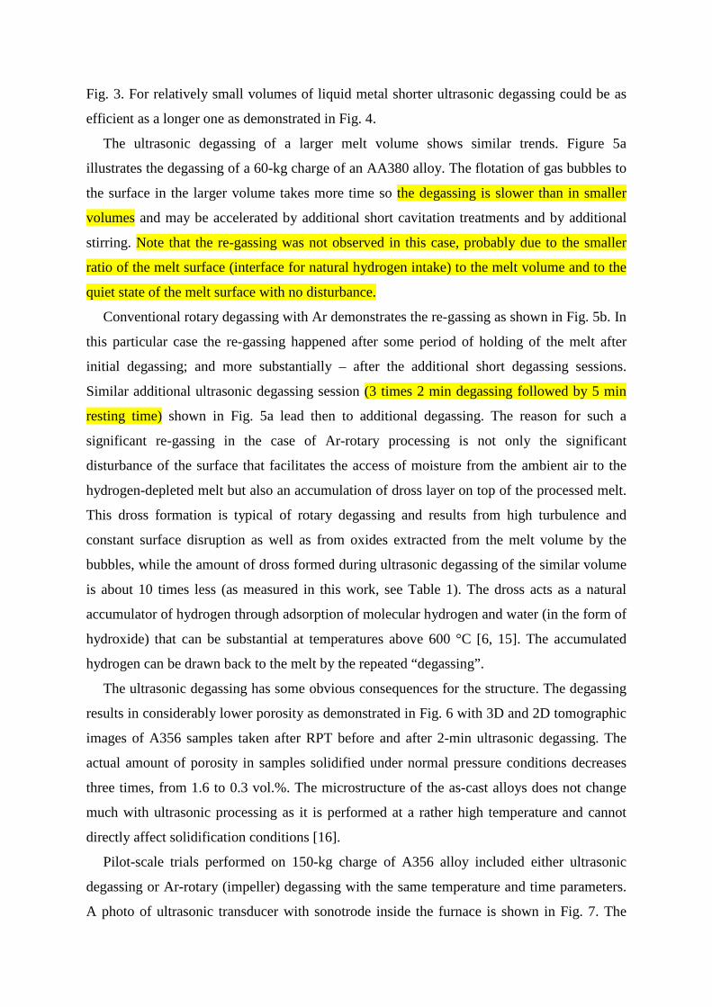
Fig. 3. For relatively small volumes of liquid metal shorter ultrasonic degassing could be as
efficient as a longer one as demonstrated in Fig. 4.
The ultrasonic degassing of a larger melt volume shows similar trends. Figure 5a
illustrates the degassing of a 60-kg charge of an AA380 alloy. The flotation of gas bubbles to
the surface in the larger volume takes more time so the degassing is slower than in smaller
volumes and may be accelerated by additional short cavitation treatments and by additional
stirring. Note that the re-gassing was not observed in this case, probably due to the smaller
ratio of the melt surface (interface for natural hydrogen intake) to the melt volume and to the
quiet state of the melt surface with no disturbance.
Conventional rotary degassing with Ar demonstrates the re-gassing as shown in Fig. 5b. In
this particular case the re-gassing happened after some period of holding of the melt after
initial degassing; and more substantially – after the additional short degassing sessions.
Similar additional ultrasonic degassing session (3 times 2 min degassing followed by 5 min
resting time) shown in Fig. 5a lead then to additional degassing. The reason for such a
significant re-gassing in the case of Ar-rotary processing is not only the significant
disturbance of the surface that facilitates the access of moisture from the ambient air to the
hydrogen-depleted melt but also an accumulation of dross layer on top of the processed melt.
This dross formation is typical of rotary degassing and results from high turbulence and
constant surface disruption as well as from oxides extracted from the melt volume by the
bubbles, while the amount of dross formed during ultrasonic degassing of the similar volume
is about 10 times less (as measured in this work, see Table 1). The dross acts as a natural
accumulator of hydrogen through adsorption of molecular hydrogen and water (in the form of
hydroxide) that can be substantial at temperatures above 600 °C [6, 15]. The accumulated
hydrogen can be drawn back to the melt by the repeated “degassing”.
The ultrasonic degassing has some obvious consequences for the structure. The degassing
results in considerably lower porosity as demonstrated in Fig. 6 with 3D and 2D tomographic
images of A356 samples taken after RPT before and after 2-min ultrasonic degassing. The
actual amount of porosity in samples solidified under normal pressure conditions decreases
three times, from 1.6 to 0.3 vol.%. The microstructure of the as-cast alloys does not change
much with ultrasonic processing as it is performed at a rather high temperature and cannot
directly affect solidification conditions [16].
Pilot-scale trials performed on 150-kg charge of A356 alloy included either ultrasonic
degassing or Ar-rotary (impeller) degassing with the same temperature and time parameters.
A photo of ultrasonic transducer with sonotrode inside the furnace is shown in Fig. 7. The
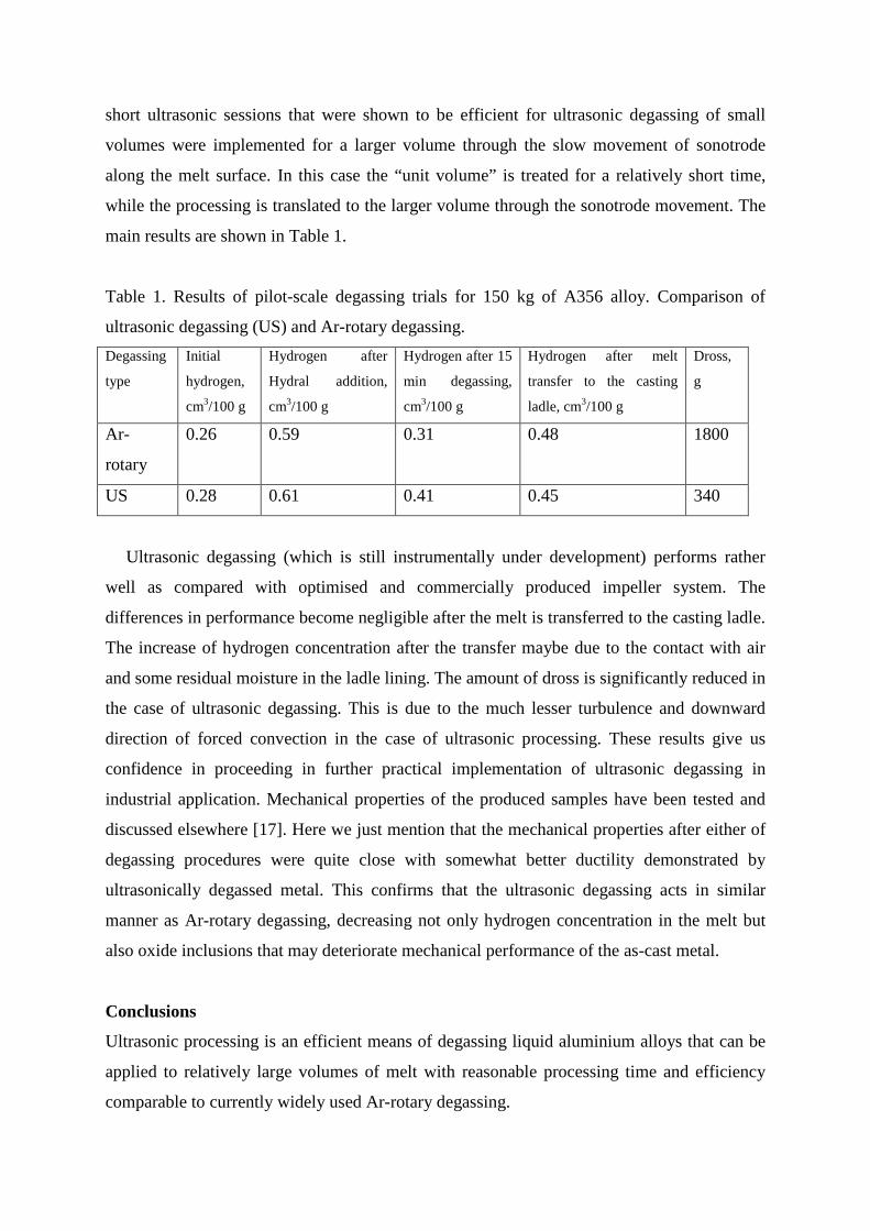
short ultrasonic sessions that were shown to be efficient for ultrasonic degassing of small
volumes were implemented for a larger volume through the slow movement of sonotrode
along the melt surface. In this case the “unit volume” is treated for a relatively short time,
while the processing is translated to the larger volume through the sonotrode movement. The
main results are shown in Table 1.
Table 1. Results of pilot-scale degassing trials for 150 kg of A356 alloy. Comparison of
ultrasonic degassing (US) and Ar-rotary degassing. Degassing
type
Initial
hydrogen,
cm3/100 g
Hydrogen after
Hydral addition,
cm3/100 g
Hydrogen after 15
min degassing,
cm3/100 g
Hydrogen after melt
transfer to the casting
ladle, cm3/100 g
Dross,
g
Ar-
rotary
0.26 0.59 0.31 0.48 1800
US 0.28 0.61 0.41 0.45 340
Ultrasonic degassing (which is still instrumentally under development) performs rather
well as compared with optimised and commercially produced impeller system. The
differences in performance become negligible after the melt is transferred to the casting ladle.
The increase of hydrogen concentration after the transfer maybe due to the contact with air
and some residual moisture in the ladle lining. The amount of dross is significantly reduced in
the case of ultrasonic degassing. This is due to the much lesser turbulence and downward
direction of forced convection in the case of ultrasonic processing. These results give us
confidence in proceeding in further practical implementation of ultrasonic degassing in
industrial application. Mechanical properties of the produced samples have been tested and
discussed elsewhere [17]. Here we just mention that the mechanical properties after either of
degassing procedures were quite close with somewhat better ductility demonstrated by
ultrasonically degassed metal. This confirms that the ultrasonic degassing acts in similar
manner as Ar-rotary degassing, decreasing not only hydrogen concentration in the melt but
also oxide inclusions that may deteriorate mechanical performance of the as-cast metal.
Conclusions
Ultrasonic processing is an efficient means of degassing liquid aluminium alloys that can be
applied to relatively large volumes of melt with reasonable processing time and efficiency
comparable to currently widely used Ar-rotary degassing.
Short processing times separated by gas-release idle periods can be used in ultrasonic
degassing practice. For large volumes this intermittent regime can be substituted for
sonotrode movement.
Melt degassing is followed by re-gassing stage with the magnitude of re-gassing being
dependent on the extent of degassing below the quasi-equilibrium hydrogen concentration
under given environmental conditions.
Ultrasonic degassing is accompanied by significant decrease in dross formation as
compared to Ar-rotary degassing, which stipulates lesser re-gassing during repeated
degassing sessions and also leads to lesser metal loss during degassing.
Acknowledgements
The research leading to these results has received funding from the European Union’s
Seventh Framework Program managed by REA – Research Executive Agency (FP7/2007-
2013) under Grant Agreement number 286344 (www.ultragassing.eu).
References
[1] J. Campbell: ‘Castings’, 2nd revised edition, 1993, Oxford, UK, Butterworth-Heinemann
Ltd.
[2] P.D. Waite: ‘Improved metallurgical understanding of the ALCAN compact degasser
after two years of industrial implementation in aluminum casting plants’, in ‘Light Metals
1998’, (ed. B. Welch), 791–796; 1998, Warrendale, OH, The Minerals, Metals & Materials
Society.
[3] D. Dispinar, J. Campbell: ‘Critical assessment of reduced pressure test. Part 1: Porosity phenomena‘, Int. J. Cast Metals Res., 2004, 17, 280–286. [4] A. San-Martin and F.D. Manchester: ‘The Al–H (aluminum–hydrogen) system’, J. Phase
Equilibr., 1992, 13, 17–21.
[5] O.A. Kapustina: ‘Degassing of liquids’, in ‘Physical principles of ultrasonic technology’,
(ed. L.D. Rozenberg), Vol. 1, Ch. 5, 1973, New York, Plenum Press.
[6] V.I. Dobatkin, R.M. Gabidullin, B.A. Kolachev, and G.S. Makarov: ‘Gases and oxides in
wrought aluminium alloys’, 1975, Moscow, Metallurgiya.
[7] G.I Eskin: ‘Ultrasonic processing of molten aluminium’, 1965, Moscow, Metallurgiya.
[8] G.I. Eskin: ‘Ultrasonic treatment of light alloy melts’, 1998, Amsterdam, Gordon&Breach
OPA.
[9] H. Xu, Q. Han, and T. T. Meek: ‘Effects of ultrasonic vibration on degassing of aluminum
alloys’, Mater. Sci. Eng. A, 2008, 473, 96–104.
[10] H. Puga, J. Barbosa, E. Seabra, S. Ribeiro, and M. Prokic: ‘The influence of processing
parameters on the ultrasonic degassing of molten AlSi9Cu3 aluminium alloy’, Mater. Lett.,
2009, 63, 806–808.
[11] G. K. Sigworth and T.A Engh: ‘Chemical and kinetic factors related to hydrogen
removal from aluminum’, Metall. Trans. B, 1982, 13, 447–460.
[12] W.R. Opie and N.J. Grant: ‘Hydrogen solubility in aluminum and some aluminum
alloys’, Trans. AIME, 1950, 188, 1237–1241.
[13] N. Alba-Baena and D.G. Eskin: ‘Kinetics of ultrasonic degassing of aluminum alloys’,
in ‘Light Metals 2013’, (ed. B. Sadler), 957–962; 2013, Warrendale, OH, The Minerals,
Metals & Materials Society.
[14] P.N. Anyalebechi: ‘Critical review of reported values of hydrogen diffusion in solid and
liquid aluminum and its alloys’, in ‘Light Metals 2003’. (ed. P.N. Crepeau), 857–872; 2003,
Warrendale, The Minerals, Metals & Materials Society.
[15] G.S. Makarov: ‘Cleaning of aluminium melt by gases’, 8–24; 1983, Moscow,
Metallurgiya.
[16] N. Alba-Baena, T. Pabel, N. Villa-Sierra, and D. Eskin: ‘Effect of ultrasonic melt
treatment on degassing and structure of aluminium alloys’, Mater. Sci. Forum, 2013, 765,
271–275.
[17] M. da Silva, L. Rebolledo, T. Pabel, T. Petkov, X. Planta, J. Tort, and D. Eskin:
‘Evaluation of the effect of ultrasonic degassing on components produced by low pressure die
casting’, Intern. J. Cast Metals Res., 2014 (submitted).
Figure captions
Figure 1. Correlation graphs between direct hydrogen readings (ALSPEK-H) and density
index (RPT) for (a) A380 and (b) A356 alloys.
Figure 2. Ultrasonic degassing kinetics: (a) 2-min degassing of a 4-kg A380 charge, values
converted from the density indices using RPT (DI) and measured using ALSPEK-H (AL).
For reference, the graph shows lines of the stabilization or quasi-equilibrium level (S) and
hydrogen equilibrium ([H]e) and (b) degassing of 4-kg charges of A356 and A380 after the
same degassing and ambient conditions.
Figure 3. Kinetics of degassing for a 2-kg A380 melt showing the efficiency of 2-min
intermittent treatment as measured by ALSPEK-H.
Figure 4. Efficiency of degassing (decrease of hydrogen concentration from the initial one)
for 2-kg charges of A380 alloy treated with ultrasound for (1) 30 s; (2) 1 min; (3) 2 min; (4) 3
min and (5) 5 min with 5 min idle intervals between degassing sessions, three cycles are
shown.
Figure 5. Kinetics of degassing of a 60-kg charge of (a) A380 alloy (ultrasonic degassing)
and (b) A356 alloy (Ar rotary degassing), the notations are the same as in Fig. 2.
Figure 6. Computer tomography of RPT samples of A356 alloys before (a, b) and after (c, d)
2-min ultrasonic degassing.
Figure 7. Photograph of an ultrasonic transducer and sonotrode inside a 150-kg crucible
during degassing trials.
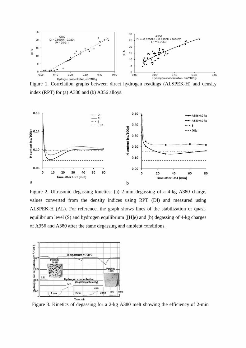
Figure 1. Correlation graphs between direct hydrogen readings (ALSPEK-H) and density
index (RPT) for (a) A380 and (b) A356 alloys.
a b
Figure 2. Ultrasonic degassing kinetics: (a) 2-min degassing of a 4-kg A380 charge,
values converted from the density indices using RPT (DI) and measured using
ALSPEK-H (AL). For reference, the graph shows lines of the stabilization or quasi-
equilibrium level (S) and hydrogen equilibrium ([H]e) and (b) degassing of 4-kg charges
of A356 and A380 after the same degassing and ambient conditions.
Figure 3. Kinetics of degassing for a 2-kg A380 melt showing the efficiency of 2-min

intermittent treatment as measured by ALSPEK-H.
Figure 4. Efficiency of degassing (decrease of hydrogen concentration from the initial on kg charges of A380 alloy treated with ultrasound for (1) 30 s; (2) 1 min; (3) 2 min; (4) 3 (5) 5 min with 5 min idle intervals between degassing sessions, three cycles are shown.
a b
Figure 5. Kinetics of degassing of a 60-kg charge of (a) A380 alloy (ultrasonic degassing) and (b) A356 alloy (Ar rotary degassing), the notations of the solubilities are the same as in Fig. 2.
a c
b d
Figure 6. Computer tomography of RPT samples of A356 alloys before (a, b) and after (c, d) 2-min ultrasonic degassing.
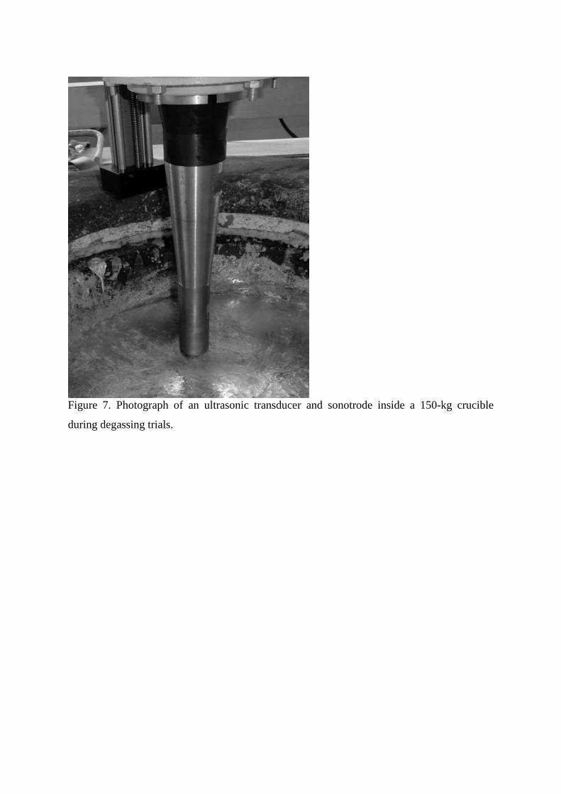
Figure 7. Photograph of an ultrasonic transducer and sonotrode inside a 150-kg crucible
during degassing trials.