Ultrasonic Based Distance Measurement System...EE616 Electronic Design Lab Project Report, EE Dept,...
22
EE616 Electronic Design Lab Project Report, EE Dept, IIT Bombay, November 2007 Ultrasonic Based Distance Measurement System Group No: 06 Vidyadhar Kamble (07307501) Dipesh Makwana (06323302) C.Chandramouli (07307601) Supervisor: Prof. P.C. Pandey Abstract The report details the implementation of distance measurement system using the ultrasonic waves. As the human ear’s audible perception range is 20 Hz to 20 kHz, it is insensitive to ultrasonic waves, and hence the ultrasound waves can be used for applications in industries/vehicles without hindering human activity. They are widely used as range meters and proximity detectors in industries also it can be used in parking assistance system. The distance can be measured using pulse echo and phase measurement method. Here the pulse echo method is used. The measurement unit uses a continuous signal in the transmission frequency range of ultrasonic transducers. The signal is transmitted by an ultrasonic transducer, reflected by an obstacle and received by another transducer where the signal is detected. The time delay of the transmitted and the received signal corresponds to the distance between the system and the obstacle.
Transcript of Ultrasonic Based Distance Measurement System...EE616 Electronic Design Lab Project Report, EE Dept,...
EE616 Electronic Design Lab Project Report, EE Dept, IIT Bombay, November 2007
Ultrasonic Based Distance Measurement System
Group No: 06
Vidyadhar Kamble (07307501)
Dipesh Makwana (06323302)
C.Chandramouli (07307601)
Supervisor: Prof. P.C. Pandey
Abstract
The report details the implementation of distance measurement system using the ultrasonic waves. As the human ear’s audible perception range is 20 Hz to 20 kHz, it is insensitive to ultrasonic waves, and hence the ultrasound waves can be used for applications in industries/vehicles without hindering human activity. They are widely used as range meters and proximity detectors in industries also it can be used in parking assistance system. The distance can be measured using pulse echo and phase measurement method. Here the pulse echo method is used. The measurement unit uses a continuous signal in the transmission frequency range of ultrasonic transducers. The signal is transmitted by an ultrasonic transducer, reflected by an obstacle and received by another transducer where the signal is detected. The time delay of the transmitted and the received signal corresponds to the distance between the system and the obstacle.
1
1. Introduction The techniques of distance measurement using ultrasonic in air include continuous wave
and pulse echo technique. In the pulse echo method, a burst of pulses is sent through the transmission medium and is reflected by an object kept at specified distance. The time taken for the pulse to propagate from transmitter to receiver is proportional to the distance of object. For contact less measurement of distance, the device has to rely on the target to reflect the pulse back to itself. The target needs to have a proper orientation that is it needs to be perpendicular to the direction of propagation of the pulses. The amplitude of the received signal gets significantly attenuated and is a function of nature of the medium and the distance between the transmitter and target. The pulse echo or time-of-flight method of range measurement is subject to high levels of signal attenuation when used in an air medium, thus limiting its distance range. 2. Design procedure
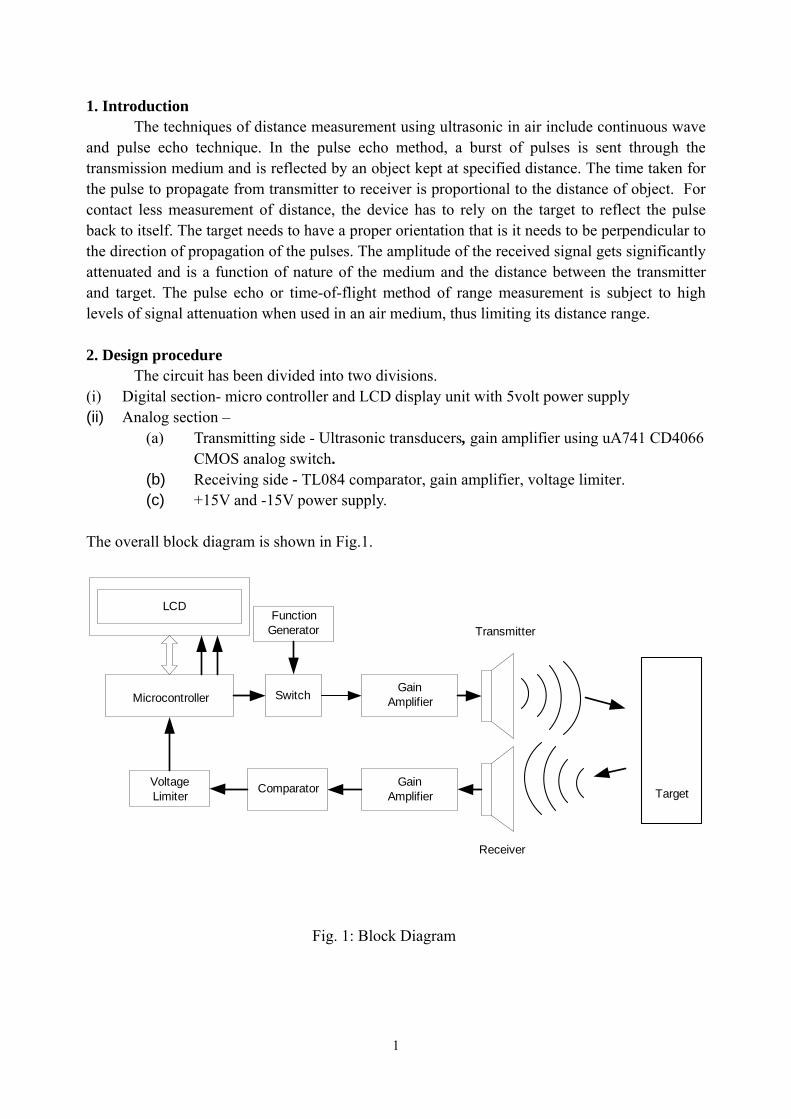
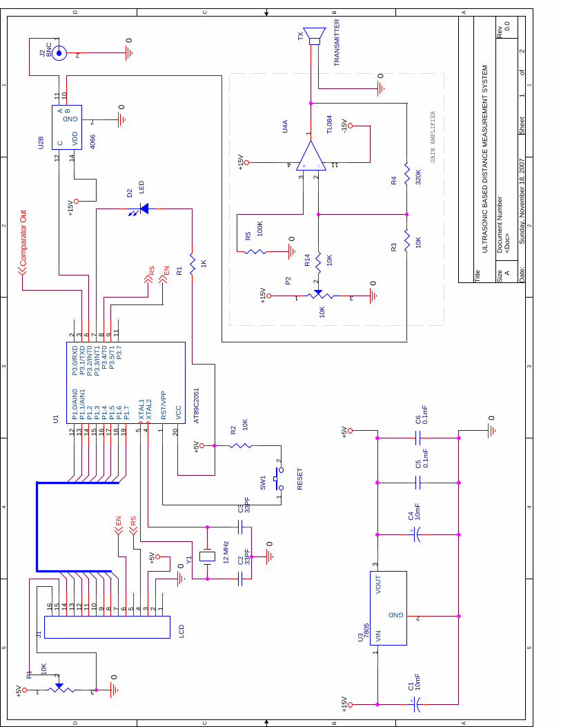
The circuit has been divided into two divisions. (i) Digital section- micro controller and LCD display unit with 5volt power supply (ii) Analog section –
(a) Transmitting side - Ultrasonic transducers, gain amplifier using uA741 CD4066 CMOS analog switch.
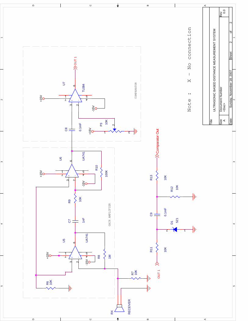
(b) Receiving side - TL084 comparator, gain amplifier, voltage limiter. (c) +15V and -15V power supply.
The overall block diagram is shown in Fig.1.
GainAmplifier
GainAmplifier
Comparator
LCD
VoltageLimiter
Microcontroller Switch
FunctionGenerator Transmitter
Receiver
Target
Fig. 1: Block Diagram
2
2.1 Transmitting unit Switch An analog switch CD4066 is used to allow the sine wave from function generator to the gain amplifier. The excitation to the Transmitter is given from the Function generator through the switch which can be digitally controlled. As the switch can pass only positive voltages, the 40kHz, 1Vp-p, sine wave from the function generator is given a DC shift of 0.5V. Microcontroller.
This system of distance measurement does not require large amount of memory, hence a 20 pin 8051 based microcontroller AT89C2051, is chosen as the controller with 12MHz clock. It performs the operation of giving the switching signal, computing the distance, converting the hex value to decimal and then to ASCII to be displayed in the LCD. Gain Amplifier
As the 40 kHz sine wave cannot be passed through the analog switch 4066, a gain amplifier with level shifter is required. Both are integrated and built using μA741 opamp. 2.2 Receiver unit Amplifier
The frequency of the received pulse is of 40 kHz which requires amplifiers working at high frequency. TL084 is used, as it has good high frequency gain characteristics. The gain of the amplifier is set to 1000 in two stages with first being 100 and second being 10. The gain is set by taking into account the least magnitude (50mV) of the receiver output when sensing an object at distance of 2 metres.
Comparator
The output signal from the amplifier is passed through the comparator which compares with a reference threshold level to weed out the noises and false triggering. The signal is a series of square pulses as shown in Fig.1 with amplitude of 15 volts. This is passed through the voltage limiter (zener regulator) to be fed to the microcontroller for counting the pulses. 3. Description
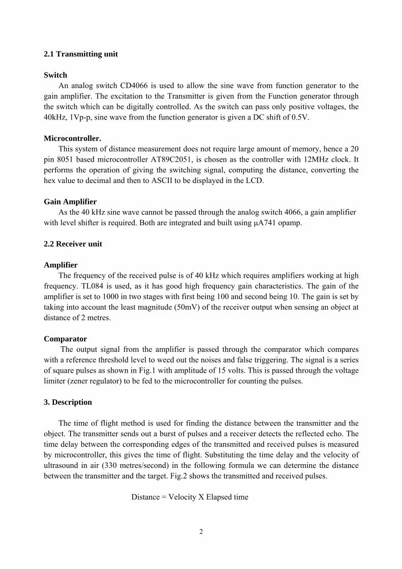
The time of flight method is used for finding the distance between the transmitter and the object. The transmitter sends out a burst of pulses and a receiver detects the reflected echo. The time delay between the corresponding edges of the transmitted and received pulses is measured by microcontroller, this gives the time of flight. Substituting the time delay and the velocity of ultrasound in air (330 metres/second) in the following formula we can determine the distance between the transmitter and the target. Fig.2 shows the transmitted and received pulses. Distance = Velocity X Elapsed time
3
10 cycles of 40kHz 20Vp-p sine wave
Ouput of receiver after amplification
Comparator Output
950µs
Time of flight = 950µsDistance measured = 330 = 0.347 metres 950µs
Fig.2 Transmitted and Received Pulses
Microcontroller calculates the distance by the above formula. This distance is twice of the required distance. Hence it is reduced to half and this calculated distance is displayed on the LCD. The LCD is refreshed every 250 milliseconds.
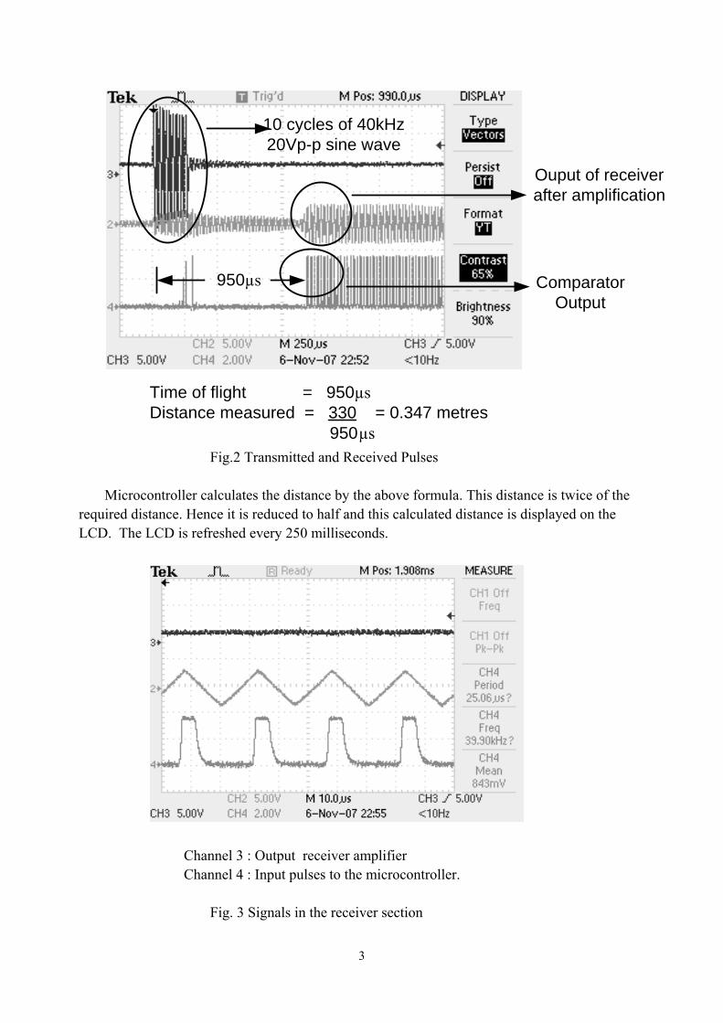
Channel 3 : Output receiver amplifier Channel 4 : Input pulses to the microcontroller. Fig. 3 Signals in the receiver section
4
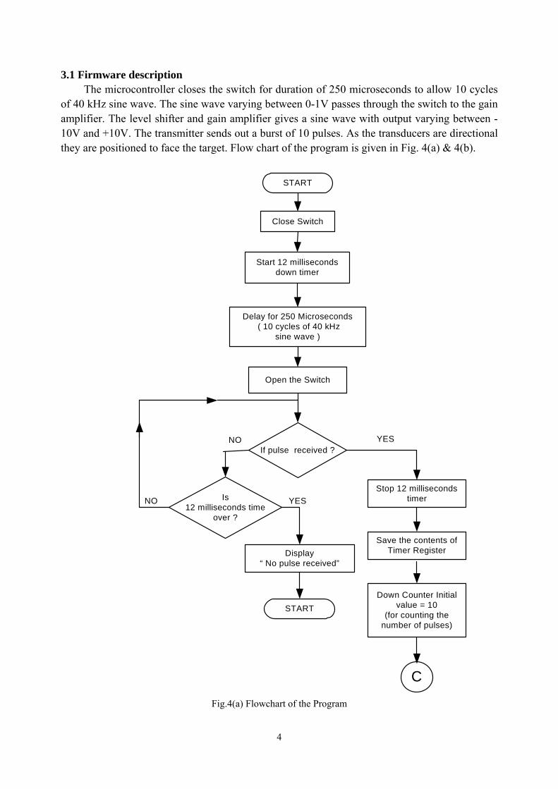
3.1 Firmware description The microcontroller closes the switch for duration of 250 microseconds to allow 10 cycles of 40 kHz sine wave. The sine wave varying between 0-1V passes through the switch to the gain amplifier. The level shifter and gain amplifier gives a sine wave with output varying between -10V and +10V. The transmitter sends out a burst of 10 pulses. As the transducers are directional they are positioned to face the target. Flow chart of the program is given in Fig. 4(a) & 4(b).
START
Close Switch
If pulse received ?
Open the Switch
Stop 12 milliseconds timer
Start 12 milliseconds down timer
Is 12 milliseconds time
over ?
Delay for 250 Microseconds ( 10 cycles of 40 kHz
sine wave )
Save the contents of Timer Register
YES
YESNO
Down Counter Initial value = 10
(for counting the number of pulses)
NO
START
Display “ No pulse received”
C
Fig.4(a) Flowchart of the Program
5
If no of pulse received
= 10 ?
NO
Decrement Counter
Start 25 microseconds down timer
If pulse received
Is 25 microseconds
time over ?
Time of flight = Observed time – 12 milliseconds
YES
NO
Actual time = Time of flight 2
Distance = Velocity X Actual time
Convert Decimal to its ASCII equivalent
Display the calculated measurement in LCD
If Computing for the
first time ?
YESNO
Update the measurement in LCD
YES
START
YESNO
Convert Hex to decimal
START
C
Fig.4(b) Flowchart of the Program.
6
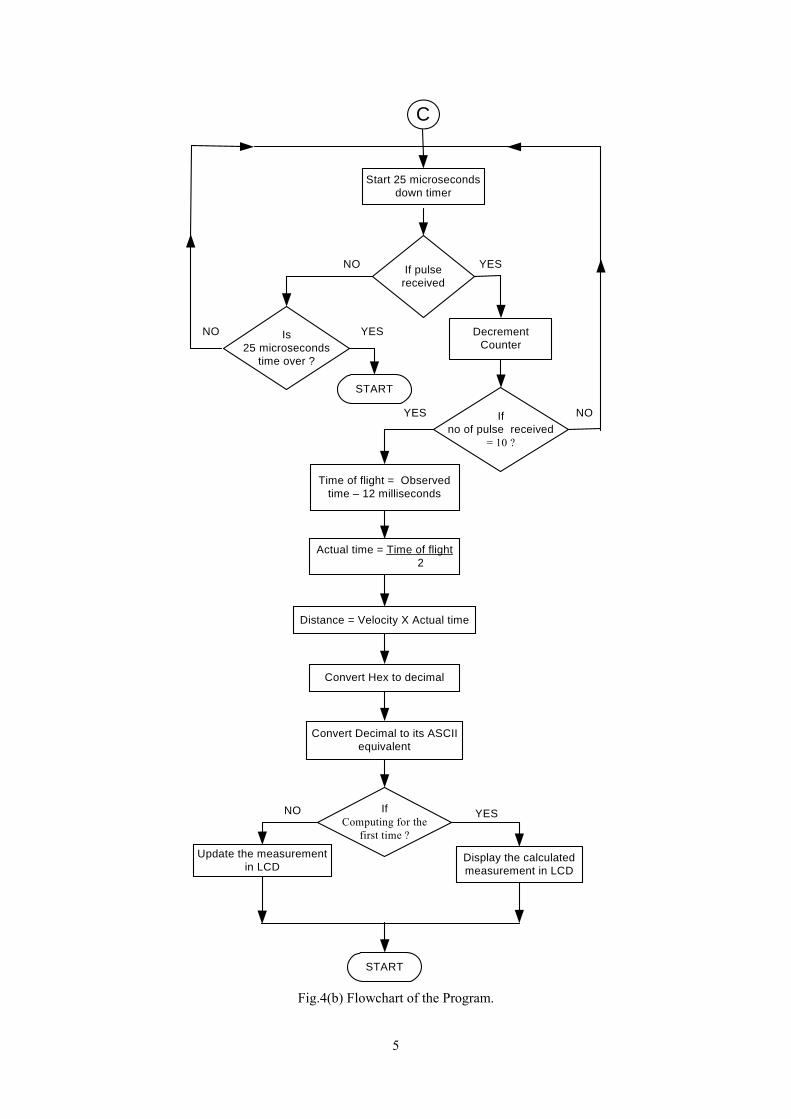
The microcontroller waits to receive the pulses for a maximum duration of 12 milliseconds. This is the time taken for the ultrasound waves to travel a maximum distance of 4 metres (time of flight gives twice the time taken to traverse a unit distance). If it doesn’t receive the pulses within this time it is considered as absence of object or object out of range. Once the pulses are received the microcontroller counts 10 pulses with a time spacing of 25 microseconds only then the measurement is considered valid and the computation using the formula is implemented. Necessary hex to decimal conversion and decimal to ASCII conversions are performed to display the output of the computation in the LCD. The appendix gives the detailed program with necessary comments for this application. 4. Conclusion
The microcontroller with LCD makes it user friendly and can be embedded in a single unit. The circuit has been implemented on bread board and tested for its functionality by varying the distance between the transducer and the target. The target surface needs to be perpendicular to the impinging ultrasound waves. The power level of the signal is too low for long range measurement.
5. Future Work
• The range can be considerably increased by using high power drive circuit. • Using temperature compensation, it can be used over wide temperature range. • The resolution of the measurement can be improved by incorporating phase shift method along with
time of flight method. • Can be used as parking assistance system in vehicles with high power ultrasonic transmitter. • The 40 kHz signal can be generated using microcontroller itself which will reduce hardware.
6. Acknowledgement
We express our deep gratitude to Prof P. C. Pandey for his timely and valuable guidance for the successful completion of the project. We also like to thank the WEL lab RAs, TAs, and Staff for their continuous support. Doing this work was a really a lot of fun as we could get our hand on the practical applications of electronic principles also it was a very good learning experience as a group.

7
References: [1] Mazidi, Muhammad Ali, 8051 Microcontroller and Embedded Systems, The (1st Edition) 1999, Prentice Hall [2] K. J. Ayala, 8051 Microcontroller, Architecture, Programming & Applications, Second Edition, Penram International Publishing (India), Mumbai, 1998. [3] “A high accuracy ultrasonic distance measurement system using binary frequency shift-keyed signal and phase detection” Huang et al review of scientific instruments volume73, number 10 october 2002. [4] Datasheets of all the components involved (AT89C2051, IC 4066, IC 7805, IC TL084, UA 741)
8
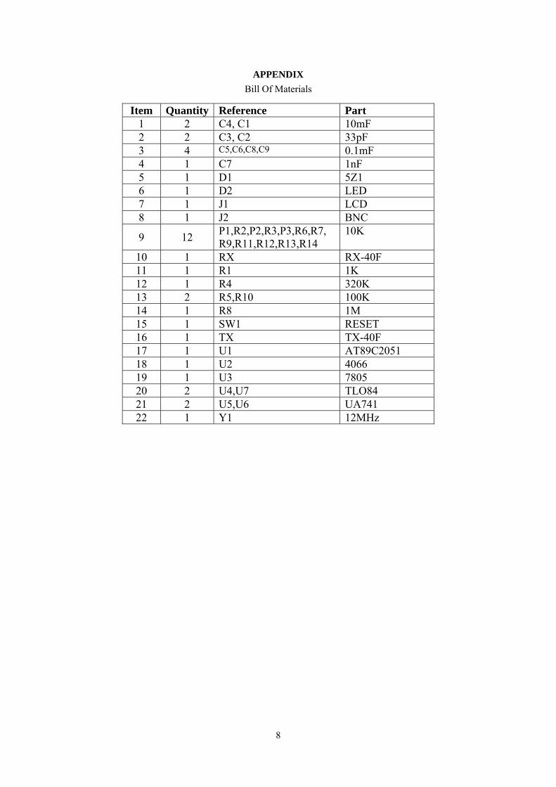
APPENDIX Bill Of Materials
Item Quantity Reference Part 1 2 C4, C1 10mF 2 2 C3, C2 33pF 3 4 C5,C6,C8,C9 0.1mF 4 1 C7 1nF 5 1 D1 5Z1 6 1 D2 LED 7 1 J1 LCD 8 1 J2 BNC
9 12 P1,R2,P2,R3,P3,R6,R7, R9,R11,R12,R13,R14
10K
10 1 RX RX-40F 11 1 R1 1K 12 1 R4 320K 13 2 R5,R10 100K 14 1 R8 1M 15 1 SW1 RESET 16 1 TX TX-40F 17 1 U1 AT89C2051 18 1 U2 4066 19 1 U3 7805 20 2 U4,U7 TLO84 21 2 U5,U6 UA741 22 1 Y1 12MHz
5 5
4 4
3 3
2 2
1 1
DD
CC
BB
AA
GAIN AMPLIFIER
<Doc
>0.
0
ULT
RA
SO
NIC
BA
SE
D D
ISTA
NC
E M
EA
SU
RE
ME
NT
SY
STE
M
A
12
Sun
day,
Nov
embe
r 18,
200
7
Title
Size
Doc
umen
t Num
ber
Rev
Dat
e:S
heet
of
RS
ENC
ompa
rato
r Out
RS
EN
0
+15V
+5V
0
+15V
-15V
+15V
00
0
+15V
0
+5V
0
+5V
+5V
0
0
D2 LE
D
SW
1
RE
SE
T
12
P1 10
K1 3
2
Y1
12 M
Hz
C5 0.1m
FC
60.
1mF
R3 10
K
C3
33P
F
+C
410
mF
R4
320K
U2B
4066
11 1014
7
12A B
VD
D
GND
C
R2 10
K
J1 LCD
12345678910111213141516J2 B
NC
1
2
C2
33P
FR
5 100K
U1
AT8
9C20
51
1 205 412 13 14 15 16 17 18 19
2 3 6 7 8 9 11
RS
T/V
PP
VC
C
XTA
L1X
TAL2
P1.
0/A
IN0
P1.
1/A
IN1
P1.
2P
1.3
P1.
4P
1.5
P1.
6P
1.7
P3.
0/R
XD
P3.
1/TX
DP
3.2/
INT0
P3.
3/IN
T1P
3.4/
T0P
3.5/
T1P
3.7
+ -
U4A
TL08
4
3 21
4 11
TX
TRA
NS
MIT
TER
P2
10K
1 3
2R
14
10K
U3 78
051
2
3V
IN
GND
VO
UT
+C
110
mF
R1 1K
5 5
4 4
3 3
2 2
1 1
DD
CC
BB
AA
COMPARATOR
GAIN AMPLIFIER
Note : X - No connection
<Doc
>0.
0
ULT
RA
SO
NIC
BA
SE
D D
ISTA
NC
E M
EA
SU
RE
ME
NT
SY
STE
M
A
22
Sun
day,
Nov
embe
r 18,
200
7
Title
Size
Doc
umen
t Num
ber
Rev
Dat
e:S
heet
of
OU
T 1
OU
T 1
Com
para
tor O
ut
+15V
+15V
+15V
-15V
-15V
-15V
+15V
-+
U5
UA
741
3 26
71
45
R6
10K
RX
RE
CE
IVE
R
R13
10K
R7
10K
R12 10
K
R11
10K
-+
U6
UA
741
3 26
71
45
R8
1M
P3 10
K
1 3
2
C7
1nF
R9 10
K
D1 5Z
1
12
C8
0.1m
F
C9
0.1m
F
-+
U7
TL08
4
3 26
71
45
R10
100K
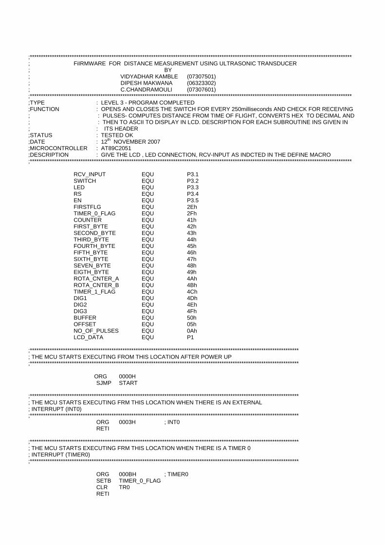
;************************************************************************************************************************************************** ; FiIRMWARE FOR DISTANCE MEASUREMENT USING ULTRASONIC TRANSDUCER ; BY ; VIDYADHAR KAMBLE (07307501) ; DIPESH MAKWANA (06323302) ; C.CHANDRAMOULI (07307601) ;************************************************************************************************************************************************** ;TYPE : LEVEL 3 - PROGRAM COMPLETED ;FUNCTION : OPENS AND CLOSES THE SWITCH FOR EVERY 250milliseconds AND CHECK FOR RECEIVING ; : PULSES- COMPUTES DISTANCE FROM TIME OF FLIGHT, CONVERTS HEX TO DECIMAL AND ; : THEN TO ASCII TO DISPLAY IN LCD. DESCRIPTION FOR EACH SUBROUTINE INS GIVEN IN ; : ITS HEADER ;STATUS : TESTED OK ;DATE : 12th NOVEMBER 2007 ;MICROCONTROLLER : AT89C2051 ;DESCRIPTION : GIVE THE LCD , LED CONNECTION, RCV-INPUT AS INDCTED IN THE DEFINE MACRO ;************************************************************************************************************************************************** RCV_INPUT EQU P3.1 SWITCH EQU P3.2 LED EQU P3.3 RS EQU P3.4 EN EQU P3.5 FIRSTFLG EQU 2Eh TIMER_0_FLAG EQU 2Fh COUNTER EQU 41h FIRST_BYTE EQU 42h SECOND_BYTE EQU 43h THIRD_BYTE EQU 44h FOURTH_BYTE EQU 45h FIFTH_BYTE EQU 46h SIXTH_BYTE EQU 47h SEVEN_BYTE EQU 48h EIGTH_BYTE EQU 49h ROTA_CNTER_A EQU 4Ah ROTA_CNTER_B EQU 4Bh TIMER_1_FLAG EQU 4Ch DIG1 EQU 4Dh DIG2 EQU 4Eh DIG3 EQU 4Fh BUFFER EQU 50h OFFSET EQU 05h NO_OF_PULSES EQU 0Ah LCD_DATA EQU P1 ;************************************************************************************************************************** ; THE MCU STARTS EXECUTING FROM THIS LOCATION AFTER POWER UP ;************************************************************************************************************************** ORG 0000H SJMP START ;************************************************************************************************************************** ; THE MCU STARTS EXECUTING FRM THIS LOCATION WHEN THERE IS AN EXTERNAL ; INTERRUPT (INT0) ;************************************************************************************************************************** ORG 0003H ; INT0 RETI ;************************************************************************************************************************** ; THE MCU STARTS EXECUTING FRM THIS LOCATION WHEN THERE IS A TIMER 0 ; INTERRUPT (TIMER0) ;************************************************************************************************************************** ORG 000BH ; TIMER0 SETB TIMER_0_FLAG CLR TR0 RETI
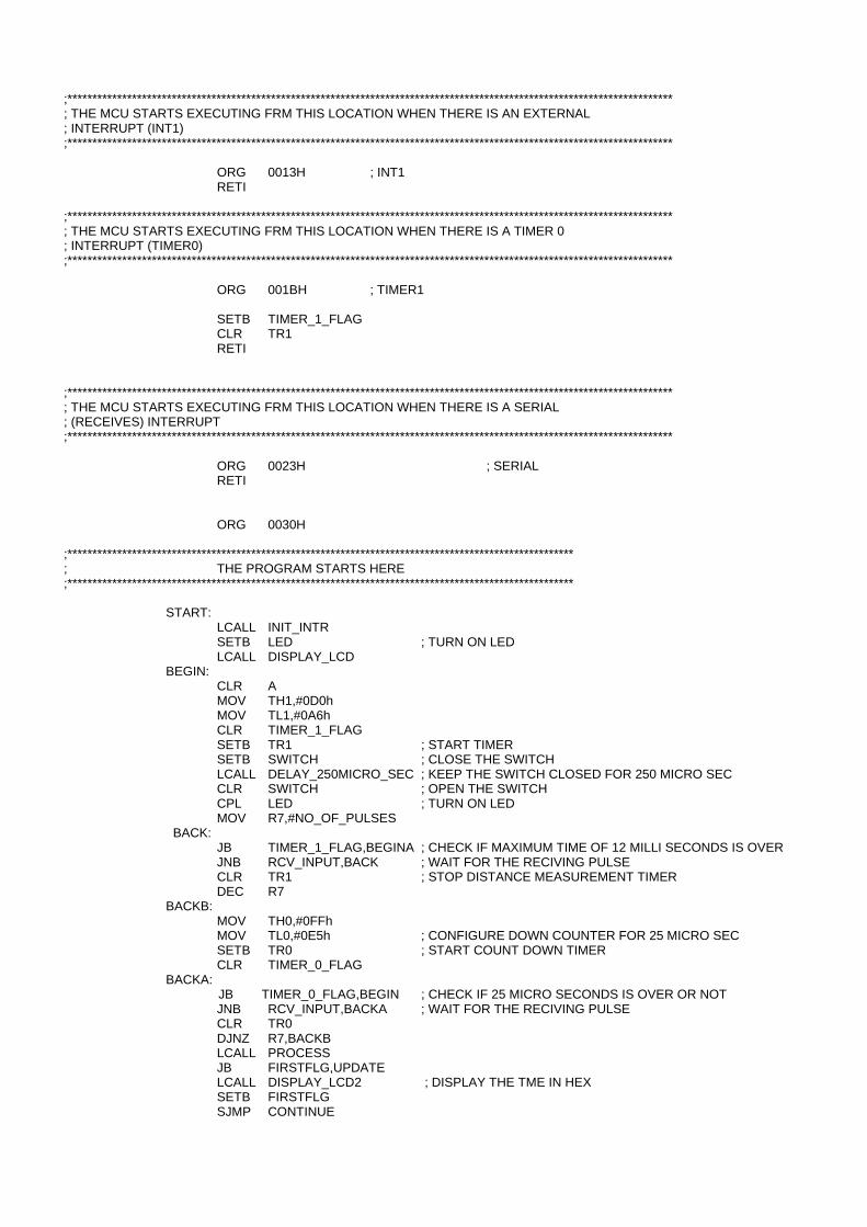
;************************************************************************************************************************** ; THE MCU STARTS EXECUTING FRM THIS LOCATION WHEN THERE IS AN EXTERNAL ; INTERRUPT (INT1) ;************************************************************************************************************************** ORG 0013H ; INT1 RETI ;************************************************************************************************************************** ; THE MCU STARTS EXECUTING FRM THIS LOCATION WHEN THERE IS A TIMER 0 ; INTERRUPT (TIMER0) ;************************************************************************************************************************** ORG 001BH ; TIMER1 SETB TIMER_1_FLAG CLR TR1 RETI ;************************************************************************************************************************** ; THE MCU STARTS EXECUTING FRM THIS LOCATION WHEN THERE IS A SERIAL ; (RECEIVES) INTERRUPT ;************************************************************************************************************************** ORG 0023H ; SERIAL RETI ORG 0030H ;****************************************************************************************************** ; THE PROGRAM STARTS HERE ;****************************************************************************************************** START: LCALL INIT_INTR SETB LED ; TURN ON LED LCALL DISPLAY_LCD BEGIN: CLR A MOV TH1,#0D0h MOV TL1,#0A6h CLR TIMER_1_FLAG SETB TR1 ; START TIMER SETB SWITCH ; CLOSE THE SWITCH LCALL DELAY_250MICRO_SEC ; KEEP THE SWITCH CLOSED FOR 250 MICRO SEC CLR SWITCH ; OPEN THE SWITCH CPL LED ; TURN ON LED MOV R7,#NO_OF_PULSES BACK: JB TIMER_1_FLAG,BEGINA ; CHECK IF MAXIMUM TIME OF 12 MILLI SECONDS IS OVER JNB RCV_INPUT,BACK ; WAIT FOR THE RECIVING PULSE CLR TR1 ; STOP DISTANCE MEASUREMENT TIMER DEC R7 BACKB: MOV TH0,#0FFh MOV TL0,#0E5h ; CONFIGURE DOWN COUNTER FOR 25 MICRO SEC SETB TR0 ; START COUNT DOWN TIMER CLR TIMER_0_FLAG BACKA:
JB TIMER_0_FLAG,BEGIN ; CHECK IF 25 MICRO SECONDS IS OVER OR NOT JNB RCV_INPUT,BACKA ; WAIT FOR THE RECIVING PULSE CLR TR0 DJNZ R7,BACKB LCALL PROCESS JB FIRSTFLG,UPDATE LCALL DISPLAY_LCD2 ; DISPLAY THE TME IN HEX SETB FIRSTFLG SJMP CONTINUE
UPDATE: LCALL UPDATE_DATA
CONTINUE: LCALL DELAY_1_SEC ; WAIT FOR ONE SECOND SJMP BEGIN BEGINA: LCALL NO_PULSE_RCVD CLR FIRSTFLG LJMP BEGIN ;****************************************************************************************************** ; THE PROGRAM ENDS HERE ;****************************************************************************************************** PROCESS: MOV R0,TH1 MOV R1,TL1 MOV R2,#0D0h MOV R3,#0A6h LCALL SUBTRACT LCALL DIVI MOV R2,#01h MOV R3,#4Ah LCALL MUL_16BIT MOV A,R5 MOV DIG3,A MOV A,R6 MOV DIG2,A MOV A,R7 MOV DIG1,A LCALL HEX2DEC LCALL CONV_2_ASCII ; CONVERT THE CONTENTS OF THE TIMER TO ASCII RET ;****************************************************************************************************** ; INTITIALIZATION ROUTINE ;****************************************************************************************************** INIT_INTR: MOV IE,#8Ah MOV TMOD,#11h ; TIMER 0 IN 16 BIT TIMER MODE , TIMER 1 IN 16 BIT TIMER MODE CLR A MOV TH0,A MOV TL0,A CLR TR0 CLR TR1 MOV P1,#00H MOV P3,#02H CLR FIRSTFLG RET ;************************************************************************************************************************** ; DSIPLAY THE DISTANCE ;**************************************************************************************************************************
DISPLAY_LCD2: LCALL CLEAR_LCD MOV DPTR,#LINE3 LCALL LINE1_DATA MOV DPTR,#LINE4 MOV COUNTER,#10h MOV R1,#BUFFER LOOP3: CLR A MOVC A,@A+DPTR MOV @R1,A INC DPTR INC R1 DJNZ COUNTER,LOOP3 LCALL LOAD_DATA LCALL DATA_FRM_BUFFER RET
;************************************************************************************************************************** ; DSIPLAY NO PULSE RECEIVED ;************************************************************************************************************************** NO_PULSE_RCVD: LCALL CLEAR_LCD MOV DPTR,#NOPULSE LCALL LINE1_DATA MOV DPTR,#NOPULSEA LCALL LINE2_DATA RET ;************************************************************************************************************************** ; LCD TEST - THIS ROUTINE IS USED FOR TESTING THE LCD. THE FUNCTIONS ; FOLLOWING THE ROUTINE ARE SUBROUTINES USED IN THE LED TESTING ROUTINES ;************************************************************************************************************************** DISPLAY_LCD: LCALL LCD_INIT LCALL CLEAR_LCD MOV DPTR,#LINE1 LCALL LINE1_DATA MOV DPTR,#LINE2 LCALL LINE2_DATA RET ;************************************************************************************************************************** ; PRINTING THE LINE 1 DATA ;************************************************************************************************************************** LINE1_DATA: MOV COUNTER,#10h ALL_DATA: CLR A MOVC A,@A+DPTR INC DPTR LCALL DATAWRT DJNZ COUNTER,ALL_DATA RET ;************************************************************************************************************************** ; PRINTING THE LINE 2 DATA ;************************************************************************************************************************** LINE2_DATA: MOV A,#0C0h ; LINE 2 STARTS FROM C0h LCALL COMNWRT MOV COUNTER,#10h AL_DATA: CLR A MOVC A,@A+DPTR INC DPTR LCALL DATAWRT DJNZ COUNTER,AL_DATA RET ;************************************************************************************************************************** ; WRITING THE DATA FROM THE BUFFER TO THE LCD'S SECOND LINE ;************************************************************************************************************************** DATA_FRM_BUFFER: MOV A,#0C0h ; LINE 2 STARTS FROM C0h LCALL COMNWRT MOV COUNTER,#10h MOV R0,#BUFFER DATA_BUF: MOV A,@R0 LCALL DATAWRT INC R0 DJNZ COUNTER,DATA_BUF RET
;************************************************************************************************************************** ; LOAD THE DATA FROM THE TIMER TO THE BUFFER ;**************************************************************************************************************************
LOAD_DATA: MOV A,#OFFSET MOV R0,#BUFFER ADD A,R0 MOV R0,A MOV A,SECOND_BYTE MOV @R0,A INC R0 MOV A,THIRD_BYTE MOV @R0,A INC R0 MOV A,FOURTH_BYTE MOV @R0,A INC R0 MOV A,#'.' MOV @R0,A INC R0 MOV A,FIFTH_BYTE MOV @R0,A INC R0 MOV A,SIXTH_BYTE MOV @R0,A INC R0 MOV A,SEVEN_BYTE MOV @R0,A INC R0 RET ;******************************************************* ; CONVERT TO ASCII ;******************************************************* CONV_2_ASCII: MOV A,R0 ANL A,#0Fh MOV DPTR,#ASCII MOVC A,@A+DPTR MOV FIRST_BYTE,A MOV A,R1 ANL A,#0Fh MOV DPTR,#ASCII MOVC A,@A+DPTR MOV SECOND_BYTE,A MOV A,R2 ANL A,#0Fh MOV DPTR,#ASCII MOVC A,@A+DPTR MOV THIRD_BYTE,A MOV A,R3 ANL A,#0Fh MOV DPTR,#ASCII MOVC A,@A+DPTR MOV FOURTH_BYTE,A MOV A,R4 ANL A,#0Fh MOV DPTR,#ASCII MOVC A,@A+DPTR MOV FIFTH_BYTE,A MOV A,R5 ANL A,#0Fh MOV DPTR,#ASCII MOVC A,@A+DPTR MOV SIXTH_BYTE,A
MOV A,R6 ANL A,#0Fh MOV DPTR,#ASCII MOVC A,@A+DPTR MOV SEVEN_BYTE,A MOV A,R7 ANL A,#0Fh MOV DPTR,#ASCII MOVC A,@A+DPTR MOV EIGTH_BYTE,A RET ;************************************************************* ; INITIALIZATION ROUTINE FOR LCD ;************************************************************* UPDATE_DATA: MOV A,#0C5h ; LINE 2 STARTS FROM C0h LCALL COMNWRT MOV A,SECOND_BYTE LCALL DATAWRT MOV A,THIRD_BYTE LCALL DATAWRT MOV A,FOURTH_BYTE LCALL DATAWRT MOV A,#'.' LCALL DATAWRT MOV A,FIFTH_BYTE LCALL DATAWRT MOV A,SIXTH_BYTE LCALL DATAWRT MOV A,SEVEN_BYTE LCALL DATAWRT RET ;************************************************************* ; INITIALIZATION ROUTINE FOR LCD ;*************************************************************
LCD_INIT: MOV A,#38H LCALL COMNWRT MOV A,#0EH LCALL COMNWRT MOV A,#06H LCALL COMNWRT RET ;************************************************************* ; CLEARING THE LCD ;*************************************************************
CLEAR_LCD: CLR RS
MOV A,#01h LCALL ROTATE MOV LCD_DATA,A SETB EN CLR EN LCALL DELAY_25MS RET ;************************************************************* ; ROUTINE TO SEND DATA ;************************************************************* DATAWRT: SETB RS LCALL ROTATE MOV LCD_DATA,A SETB EN
CLR EN LCALL DELAY_25MS RET ;************************************************************* ; ROUTINE TO SEND COMMAND ;************************************************************* COMNWRT: CLR RS LCALL ROTATE MOV LCD_DATA,A SETB EN CLR EN LCALL DELAY_25MS RET ;************************************************************* ; ROUTINE TO ROTATE THE BITS ;************************************************************* ROTATE: MOV ROTA_CNTER_A,A MOV A,ROTA_CNTER_A MOV C,ACC.7 MOV A,ROTA_CNTER_B MOV ACC.0,C MOV ROTA_CNTER_B,A MOV A,ROTA_CNTER_A MOV C,ACC.6 MOV A,ROTA_CNTER_B MOV ACC.1,C MOV ROTA_CNTER_B,A MOV A,ROTA_CNTER_A MOV C,ACC.5 MOV A,ROTA_CNTER_B MOV ACC.2,C MOV ROTA_CNTER_B,A MOV A,ROTA_CNTER_A MOV C,ACC.4 MOV A,ROTA_CNTER_B MOV ACC.3,C MOV ROTA_CNTER_B,A MOV A,ROTA_CNTER_A MOV C,ACC.3 MOV A,ROTA_CNTER_B MOV ACC.4,C MOV ROTA_CNTER_B,A MOV A,ROTA_CNTER_A MOV C,ACC.2 MOV A,ROTA_CNTER_B MOV ACC.5,C MOV ROTA_CNTER_B,A MOV A,ROTA_CNTER_A MOV C,ACC.1 MOV A,ROTA_CNTER_B MOV ACC.6,C MOV ROTA_CNTER_B,A MOV A,ROTA_CNTER_A MOV C,ACC.0 MOV A,ROTA_CNTER_B MOV ACC.7,C MOV ROTA_CNTER_B,A RET
;******************************************************* ; SUBROUTINE FOR 1 SECOND DELAY ;******************************************************* DELAY_1_SEC: MOV R0,#10 LOOP: MOV TH0,#3Ch MOV TL0,#0AFh CLR TIMER_0_FLAG SETB TR0 JNB TIMER_0_FLAG,$ DJNZ R0,LOOP RET ;******************************************************* ; SUBROUTINE FOR 2.5 MILLISECOND SECOND ;******************************************************* DELAY_250MICRO_SEC: MOV TH0,#0FFh MOV TL0,#05h CLR TIMER_0_FLAG SETB TR0 JNB TIMER_0_FLAG,$ RET ;************************************************************* ; A DELAY OF 25 milliseconds ;************************************************************* DELAY_25MS: MOV TH0,#1Eh MOV TL0,#57h CLR TIMER_0_FLAG SETB TR0 JNB TIMER_0_FLAG,$ RET ;******************************************************* ; R2 R3 - ; R0 R1 ; -------- ; R0 R1 ;******************************************************* SUBTRACT: CLR C MOV A,R1 SUBB A,R3 MOV R1,A MOV A,R0 SUBB A,R2 MOV R0,A RET ;********************************************************************************* ;MSB-> R0 R1 DIVIDEND ; R2 DIVISOR ;MSB-> R0 R1 RESULT ;********************************************************************************* DIVI: CLR C MOV A,R0 RRC A MOV R0,A MOV A,R1 RR A MOV ACC.7,C MOV R1,A RET
;************************************************************************ ;MSB-> R0 R1 MULTIPLICAND ; R2 R3 MULTIPLIER ;MSB-> R4 R5 R6 R7 RESULT ;************************************************************************ MUL_16BIT: CLR A MOV R4,A MOV R5,A MOV R6,A MOV R7,A CLR C MOV A,R1 MOV B,R3 MUL AB MOV R7,A MOV R6,B MOV A,R0 MOV B,R3 MUL AB ADD A,R6 MOV R6,A MOV A,B ADDC A,R5 MOV R5,A MOV A,R1 MOV B,R2 MUL AB ADD A,R6 MOV R6,A MOV A,B ADDC A,R5 MOV R5,A MOV A,R0 MOV B,R2 MUL AB ADDC A,R5 MOV R5,A MOV A,B ADDC A,R4 MOV R4,A RET ;************************************************************************ ; HEX TO DECIMAL CONVERSION ROUTINE ; DIG3 ;MSB ; DIG2 ; DIG1 ;LSB ; R0 R1 R2 R3 R4 R5 R6 R7 RESULT ;************************************************************************ HEX2DEC: MOV R0,#00H ; R7 MOV R1,#00H ; R6 MOV R2,#00H ; R5 MOV R3,#00H ; R0 MOV R4,#00H ; R1 MOV R5,#00H ; R2 MOV R6,#00H ; R3 MOV R7,#00H ; R4 FIRSTA: CLR C MOV A,DIG1
SUBB A,#0AH MOV DIG1,A JC OUT OUTB: INC R6 CJNE R6,#0AH,FIRS MOV R6,#00H INC R5 CJNE R5,#0AH,FIRT MOV R5,#00H INC R4 CJNE R4,#0AH,FIRU MOV R4,#00H INC R3 CJNE R3,#0AH,FIRA MOV R3,#00H INC R2 CJNE R2,#0AH,FIRB MOV R2,#00H INC R1 CJNE R1,#0AH,FIRC MOV R1,#00H INC R0 JMP FIRST FIRST: LJMP FIRSTA FIRS: JC FIRST INC R5 CJNE R5,#0AH,FIRT MOV A,R6 SUBB A,#09H MOV R6,A JMP FIRST FIRT: JC FIRST INC R4 CJNE R4,#0AH,FIRU MOV A,R5 SUBB A,#09H MOV R5,A LJMP FIRST FIRU: JC FIRST INC R3 MOV A,R4 SUBB A,#09H MOV R4,A LJMP FIRST FIRA: JC FIRST INC R2 MOV A,R3 SUBB A,#09H MOV R3,A LJMP FIRST FIRB: JC FIRST INC R1 MOV A,R2 SUBB A,#09H MOV R2,A LJMP FIRST FIRC: JC FIRST INC R0 MOV A,R1
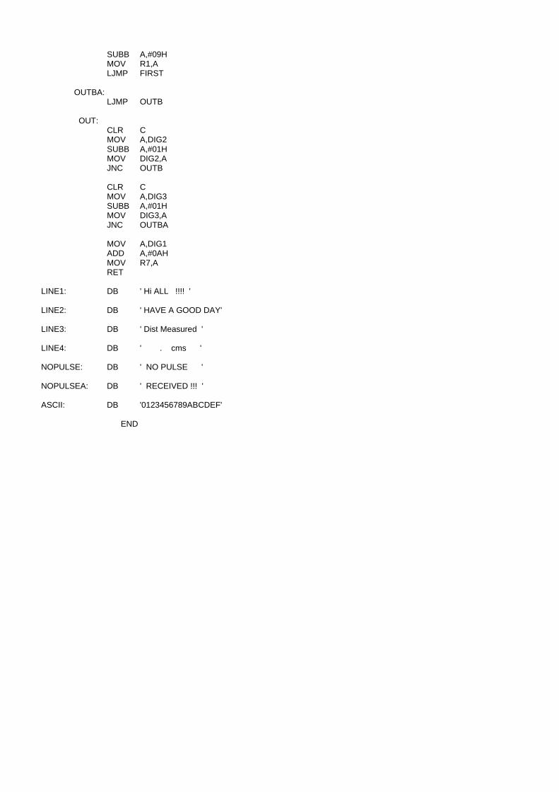
SUBB A,#09H MOV R1,A LJMP FIRST OUTBA: LJMP OUTB OUT: CLR C MOV A,DIG2 SUBB A,#01H MOV DIG2,A JNC OUTB CLR C MOV A,DIG3 SUBB A,#01H MOV DIG3,A JNC OUTBA MOV A,DIG1 ADD A,#0AH MOV R7,A RET LINE1: DB ' Hi ALL !!!! ' LINE2: DB ' HAVE A GOOD DAY' LINE3: DB ' Dist Measured ' LINE4: DB ' . cms ' NOPULSE: DB ' NO PULSE ' NOPULSEA: DB ' RECEIVED !!! ' ASCII: DB '0123456789ABCDEF' END