English Department Course Offerings. English 9 (011) English 9 (012) English 9 (013)
description

KCMU00000506/08/01
KC552xCx/KC752xCx1/3" DSPCOLOR CAMERA
USERMANUALUltrak Worldwide Support CenterSales & Technical Support1301 Waters Ridge Drive • Lewisville, TX 75057(800) 796-2288 • (972) 353-6400 • FAX (972) 353-6670
®

ii KCMU00000506/08/01
ISSUE 1 – June 2001
2001 BY ULTRAKALL RIGHTS RESERVED
ULTRAK CORPORATE OFFICE1301 WATERS RIDGE DRIVE
LEWISVILLE, TX 75057(972) 353-6500
ALL RIGHTS RESERVED. NO PART OF THIS PUBLICATION MAY BEREPRODUCED BY ANY MEANS WITHOUT WRITTEN PERMISSIONFROM ULTRAK.
THE INFORMATION IN THIS PUBLICATION IS BELIEVED TO BEACCURATE IN ALL RESPECTS. HOWEVER, ULTRAK CANNOTASSUME RESPONSIBILITY FOR ANY CONSEQUENCES RESULTINGFROM THE USE THEREOF. THE INFORMATION CONTAINEDHEREIN IS SUBJECT TO CHANGE WITHOUT NOTICE. REVISIONSOR NEW EDITIONS TO THIS PUBLICATION MAY BE ISSUED TOINCORPORATE SUCH CHANGES.

iii KCMU00000506/08/01
FCC COMPLIANCE STATEMENT
INFORMATION TO THE USER: THIS EQUIPMENT HAS BEEN TESTEDAND FOUND TO COMPLY WITH THE LIMITS FOR A CLASS B DIGITALDEVICE, PURSUANT TO PART 15 OF THE FCC RULES. THESE LIMITSARE DESIGNED TO PROVIDE REASONABLE PROTECTION AGAINSTHARMFUL INTERFERENCE IN A RESIDENTIAL INSTALLATION. THISEQUIPMENT GENERATES, USES, AND CAN RADIATE RADIOFREQUENCY ENERGY AND, IF NOT INSTALLED AND USED INACCORDANCE WITH THE INSTRUCTIONS, MAY CAUSE HARMFULINTERFERENCE TO RADIO COMMUNICATIONS. HOWEVER, THERE ISNO GUARANTEE THAT INTERFERENCE WILL NOT OCCUR IN APARTICULAR INSTALLATION. IF THIS EQUIPMENT DOES CAUSEHARMFUL INTERFERENCE TO RADIO OR TELEVISION RECEPTIONWHICH CAN BE DETERMINED BY TURNING THE EQUIPMENT OFF ANDON, THE USER IS ENCOURAGED TO TRY TO CORRECT THEINTERFERENCE BY ONE OR MORE OF THE FOLLOWING MEASURES:- REORIENT OR RELOCATE THE RECEIVING ANTENNA- INCREASE THE SEPARATION BETWEEN THE EQUIPMENT AND
RECEIVER- CONNECT THE EQUIPMENT INTO AN OUTLET ON A CIRCUIT
DIFFERENT FROM THAT TO WHICH THE RECEIVER IS CONNECTED- CONSULT THE DEALER OR AN EXPERIENCED RADIO/TV
TECHNICIAN FOR HELP
CAUTION: CHANGES OR MODIFICATIONS NOT EXPRESSLYAPPROVED BY THE PARTY RESPONSIBLE FOR COMPLIANCE COULDVOID THE USER’S AUTHORITY TO OPERATE THE EQUIPMENT.
THIS CLASS B DIGITAL APPARATUS COMPLIES WITH CANADIAN ICES-003.
CET APPAREIL NUMÉRIQUE DE LA CLASSE B EST CONFORME A LANORME NMB-003 DU CANADA.
USERS OF THE PRODUCT ARE RESPONSIBLE FOR CHECKING ANDCOMPLYING WITH ALL FEDERAL STATE AND LOCAL LAWS ANDSTATUTES CONCERNING THE MONITORING AND RECORDING OFVIDEO AND AUDIO SIGNALS. ULTRAK SHALL NOT BE HELDRESPONSIBLE FOR THE USE OF THIS PRODUCT IN VIOLATION OFCURRENT LAWS AND STATUTES.

iv KCMU00000506/08/01
WARNING
• TO REDUCE THE RISK OF FIRE OR ELECTRIC SHOCK, DO NOTEXPOSE THIS PRODUCT TO RAIN OR MOISTURE.
• DO NOT INSERT ANY METALLIC OBJECT THROUGH VENTILA-TION GRILLS.
CAUTION
CAUTION: TO REDUCE THE RISK OF ELECTRIC SHOCK, DO NOT REMOVE COVER (OR BACK).
NO USER-SERVICEABLE PARTS INSIDE.REFER SERVICING TO QUALIFIED SERVICE PERSONNEL.
C A U T I O NRISK OF ELECTRIC SHOCK
DO NOT OPEN
EXPLANATION OF GRAPHICAL SYMBOLS
The lightning flash with arrowhead symbol, within anequilateral triangle, is intended to alert the user to thepresence of uninsulated "dangerous voltage" within theproduct's enclosure that may be of sufficientmagnitude to constitute a risk of electric shock topersons.
The exclamation point within an equilateral triangle isintended to alert the user to the presence of importantoperating and maintenance (servicing) instruction inthe literature accompanying the product.

v KCMU00000506/08/01
IMPORTANT SAFEGUARDS
1. READ INSTRUCTIONS – All of the safety and operating instructions shouldbe read before the appliance is operated.
2. RETAIN INSTRUCTIONS – The safety and operating instructions should beretained for future reference.
3. HEED WARNINGS – All warnings on the product and in the operatinginstructions should be adhered to.
4. FOLLOW INSTRUCTIONS – All operating and use instructions should befollowed.
5. CLEANING – Unplug this appliance from wall outlet before cleaning. Do notuse liquid cleaners or aerosol cleaners. Use a damp cloth for cleaning.
6. ATTACHMENTS – Do not use attachments not recommended by theappliance manufacturer as they may cause hazards.
7. WATER AND MOISTURE – Do not use this product near water or moisture.(For example, near a bathtub, sink, laundry tub, in a wet basement, near aswimming pool, etc.) Unless otherwise specified, cameras may be used inoutdoor settings only when used with approved camera housing.
8. INSTALLATION – Do not place this product on an unstable cart, stand, ortable. The product may fall, causing serious injury to a child or adult, anddamage to the product. Use only with a cart or stand recommended by themanufacturer or sold with the product. Follow the manufacturer’sinstructions for mounting and use a mounting accessory recommended bythe manufacturer. Test cameras and cables prior to mounting and runningcables.
9. MOVING – Product and cart combinations should be moved withcare. Quick stops, excessive force, and uneven surfaces maycause the product and cart combination to overturn.
10. VENTILATION – Slots and openings in the cabinet and the back or bottomare provided for ventilation, to insure reliable operation of the product, and toprotect it from overheating. These openings must not be blocked orcovered. The openings should never be blocked by placing the unit on abed, sofa, rug, or other similar surface. This product should not be placed ina built-in installation, such as a bookcase, unless proper ventilation isprovided.
Continued on next page.

vi KCMU00000506/08/01
IMPORTANT SAFEGUARDS, continued
11. POWER SOURCE – This product should be operated only from the type ofpower source indicated on the marking label. If you are not sure of the typeof power supplied to your home, consult your dealer or local powercompany.
12. GROUNDING OR POLARIZATION – This camera may be equipped with apolarized alternation – current line plug (a plug having one blade wider thanthe other). This plug will fit into the power outlet only one way. This is asafety feature. If you are unable to insert the plug fully into the outlet, tryreversing the plug. If the plug should still fail to fit, contact your electrician toreplace your obsolete outlet. Do not defeat the safety purpose of thepolarized plug.
13. OVERLOADING – Do not overload wall outlets and extension cords as thiscan result in a risk of fire or electric shock.
14. REPLACEMENT PARTS – When replacement parts are required, be surethe service technician has used replacement parts specified by themanufacturer or that have the same characteristics as the original part.Unauthorized substitutions may result in fire, electric shock, or otherhazards.
15. SAFETY CHECK – Upon completion of any service or repairs to thiscamera, ask the service technician to perform safety checks to determinethat the camera is in proper operating condition.
16. FIELD INSTALLATION – This installation should be made by a qualifiedperson and should conform to all local codes.

vii KCMU00000506/08/01
PRECAUTIONS
OPERATING• Before operating, make sure that the power supply and video output are
connected correctly.• While operating, if any abnormal condition or malfunction is observed, stop
using the camera immediately and call your local dealer.
HANDLING• Do not disassemble the camera and never touch parts inside the camera.• Do not drop the camera or subject it to shocks and vibrations to avoid
possible damage.• When attaching or removing the lens, handle with care so that moisture and
dust do not enter the camera.• Do not shoot any source of bright light. If the object contains very bright
areas, bright vertical or horizontal lines may appear on the screen. This iscalled “smear” and is a phenomenon, which often occurs with solid-statepickups. It is not a malfunction.
INSTALLING AND STORING• Do not point the camera at the sun. This could damage the camera whether
it is operating or not.• Do not install the camera in extreme temperature conditions.• Be sure that the ambient temperature is less than 104°F (40°C) for long-term
continuous operation.• Avoid installing in humid or dusty places.• Avoid installing in places where there is radiation. This could damage CCD
and other components and cause malfunction.• Avoid installing in places where there are strong magnetic fields and
electrical signals.• Avoid installing in places where the camera would be subject to strong
vibrations.• Never expose the camera to rain and water.CLEANING• Turn the power off and wipe off the dirt with dry soft cloths. If it is extremely
dirty, use furniture cleaning tissue. Do not use alcohols, petroleumdistillates, liquid cleaners, or sprays.
PERFORMING DAILY CHECKS• Make daily checks for proper operation for surveillance use. In order to
maintain normal operation, the output of the camera should be checked byuser every day for a clear and focused picture.

viii KCMU00000506/08/01
THIS PAGE INTENTIONALLY LEFT BLANK.

ix KCMU00000506/08/01
TABLE OF CONTENTS
SECTION 1: INTRODUCTION...............................................................1PRODUCT DESCRIPTION...............................................................1FEATURES .......................................................................................1
SECTION 2 CONTROLS AND CONNECTIONS...................................3CAMERA – TOP................................................................................3CAMERA – BOTTOM .......................................................................6CAMERA – FRONT ..........................................................................7CAMERA – BACK .............................................................................7
SECTION 3: INSTALLATION AND ADJUSTMENT .............................9CONTENTS OF PACKAGE ..............................................................9BASIC INSTALLATION.....................................................................9INSTALLING C-MOUNT OR CS-MOUNT LENS............................10INSTALLING AUTO-IRIS LENS......................................................11INSTALLING VIDEO-TYPE AUTO-IRIS LENS...............................11ADJUSTING ALC............................................................................12ADJUSTING LEVEL........................................................................12ADJUSTING AGC ...........................................................................13INSTALLING DC-TYPE AUTO-IRIS LENS.....................................13ADJUSTING MANUAL IRIS LENS .................................................14ROUTING THE CABLE...................................................................14CONNECTING THE CABLE ...........................................................15INSTRUCTIONS FOR 24V AC MODELS.......................................15INSTRUCTIONS FOR 230V AC MODELS.....................................15
SECTION 3: TROUBLESHOOTING AND PREVENTIVEMAINTENANCE ....................................................................................19
TROUBLESHOOTING ....................................................................19PREVENTIVE MAINTENANCE ......................................................20SPECIFICATIONS ..........................................................................21

x KCMU00000506/08/01
THIS PAGE INTENTIONALLY LEFT BLANK.

1 KCMU00000506/08/01
SECTION 1:INTRODUCTION
PRODUCT DESCRIPTION
The KC552xCx/KC752xCx DSP color securitycameras provide true-color images especiallydesigned for closed-circuit television (CCTV) andsecurity surveillance applications.
FEATURES
The cameras include the following features:
• High sensitivity. 1/3" DSP color CCD technologythat provides high sensitivity down to 1.25 lux(F1.2) for the KC552xCx and 1.6 lux (F1.2) for theKC752xCx.
• High quality image. High resolution, highsensitivity design with a standard horizontalresolution of 330 TV lines or a high horizontalresolution of 470 TV lines.
• Backlight compensation. When strong lightenters the scene background, such as from aspotlight or window, the backlight compensationfunction automatically adjusts the video level topreserve visibility in important sections of theimage.
• Iris function. Iris function provides a drive outputfor video-type and DC-type lenses. A built-inelectronic shutter also allows shutter speeds inthe range of 1/60 to 1/100,000 for and 1/50 to1/100,000. CCD iris function automatically setsthe brightness of the picture by changing theshutter speed of the camera according to theincident light when using a manual iris lens.
• White balance. Both automatic and manualwhite balance modes are provided as well as fouravailable white balance settings.
Continued on next page.

2 KCMU00000506/08/01
FEATURES, continued
• Flickerless control. Flickering is removed whenthe camera signal format does not coincide withthe power source frequency.
• Automatic gain control (AGC). The AGC switchallows the video signals to maintain a constantlevel.
• Synchronization System. The cameras provideboth internal and line-lock synchronization modes.

3 KCMU00000506/08/01
SECTION 2CONTROLS AND CONNECTIONS
CAMERA – TOP
1. Auto-iris Lens Connector – This 4-pin femaleconnector allows the user to connect an auto-irislens. The connector supplies the power and avideo signal or DC control signal to the auto-irislens. (A 4-pin male connector is supplied.)
2. Camera Mounting Bracket – This threaded 1/4”-20 hole is used to mount the camera onto amounting bracket or tripod.
3. Function Switches – A switch is in the ONposition if it is positioned toward the font of thecamera. If the position is set toward the back ofthe camera, the switch is OFF. The switchesinclude the following:• SHTR Switch (AES/MES) – This switch
allows the user to choose between autoexposure (AES) and manual exposure(MES). Position the switch toward the front ofthe camera for auto exposure, whereby theexposure is performed by the electronic irisand AGC control. Position the switch towardthe back of the camera for manual exposure,whereby the shutter speed can be set by theshutter adjust.
Continued on next page.

4 KCMU00000506/08/01
CAMERA – TOP, continued
• Flickerless Switch (Off/On) – (SW1 = AutoExposure). This function is used to removeflickering when the camera signal formatdoes not coincide with the power sourcefrequency being used.
• BLC Switch (On/Off) – (SW1 = AutoExposure). This On/Off switch controlsbacklight compensation. When set to ON,the camera will automatically try to maintainproper exposure in the specific area even ifthe lighting level changes.
• E/I (On/Off) – (SW1 = Auto Exposure).When set to the ON position, the electroniciris switch automatically varies the camera’sshutter to mimic auto-iris control, allowingfixed or manual iris lenses to be used in awider range. When this switch is set to ON,turn the F/F switch OFF.
Continued on next page.

5 KCMU00000506/08/01
CAMERA – TOP, continued
• A/I Switch (DC/Video) – The auto-iris switchallows the user to select the supplied auto-iriscontrol signal for the lens. Position the switchtoward the front of the camera to choose DCwhen the auto-iris control lens requires DCcontrol signal. Position the switch toward theback of the camera to choose Video when theauto-iris control lens requires video signal.
• Gamma Switch (On/Off) – The gammacorrection switch allows .45 correction fornon-linearity gain response in the monitorwhen set to ON. When set to OFF, there isno gamma correction.
• AGC Switch (On/Off) – The auto gain controlswitch allows the video signals to maintain aconstant level. This switch is useful whenusing the camera at low-light levels and whenlighting levels change over time. For best lowlight conditions, this switch should be set toON.
• AWB1 and AWB2 Switches (On/Off) –These cameras have four white balancesettings:
1) ATW (auto tracing white balance) –The camera automatically aims tomaintain white objects as white even ifthe light color changes.
2) AWB (auto white balance) – QuickATW.
3) Indoor – Improves the color balance inareas where a mixture of light sourcesexists.
Continued on next page.

6 KCMU00000506/08/01
CAMERA – TOP, continued
4) Outdoor – Improves the color balance inareas where daylight is the main sourceof light.
• Sync Select Switch (Int/LL) – Use thisswitch to set the camera synchronizationmode to internal (Int) or Line Lock (LL).
CAMERA – BOTTOM
4. Camera Mounting Bracket – This threaded 1/4”-20 hole is used to mount the camera onto amounting bracket or tripod.

7 KCMU00000506/08/01
CAMERA – FRONT
5. C/CS Back-focus Adjust Ring – Allows the userto adjust the back-focal length or picture focus ofthe lens by rotating it clockwise for CS-mountlenses or counterclockwise for C-mount lenses.
6. Back-focus Lock Screw – Allows the user tosecure the back-focus setting.
CAMERA – BACK
Continued on next page.

8 KCMU00000506/08/01
CAMERA – BACK, continued
7. Iris Adjustment Pot (Potentiometer) – Thiscontrol allows the user to adjust the level of theauto-iris when the A/I lens selection switch is setto DC and a DC lens is mounted on the camera.The switch should be in the Video position whenan auto-iris video lens is mounted on the camera.If a video auto-iris lens is used, this control has nofunction.
8. Phase Adjustment – Phase adjustment is usedin multi-camera systems when power is suppliedfrom different sources, thus causing the camerato be out of phase. This situation affects auto-switching of the cameras by causing a vertical flipor roll of the video during the switch interval. Thevertical phase adjustment allows the camera’sline lock sync to be adjusted from 0 to 360degrees with reference to zero line crossing of theAC power source. To effectively use the phaseadjustment, ensure that all cameras are poweredfrom the same electrical source and that they arewired in a similar fashion. Then, adjust the phasecontrol on the back of the camera until there is novertical flip or roll on the monitor when using theauto-switcher.
9-1 Power Input Terminal – This terminal accepts a24V ac power source from a 24V ac +/- 10%50Hz +/- 1% (CCIR)/60 Hz +/- 1%(EIA) powersource.
9-2 AC Power Cord – This power cord accepts a230V ac +/- 10% 50Hz +/- 1% power source.
10. Power LED – This green LED illuminates whilepower is supplied to the camera.
11. Video Out Connector – This BNC connectoroutputs a 1.0 Vp-p/75 ohms composite videosignal.

9 KCMU00000506/08/01
SECTION 3:INSTALLATION AND ADJUSTMENT
CONTENTS OF PACKAGE
Carefully remove the color camera and its accessoriesfrom the carton and verify that they were not damagedin shipment.
The contents of the package include:
1. Color CCD camera2. Connector (for video- or DC-type auto-iris lens)3. User Manual
BASIC INSTALLATION
After unpacking and identifying the package contents,perform the following steps to connect the camera toan observation system.
1. Locate the following items, which may be neededduring installation yet are NOT supplied with theKC552xCx/KC752xCx cameras:• Camera lens• Video cable• Camera stand or mounting bracket• 24V ac or 230V ac power supply• Mounting hardware• Observation monitor• Welder’s glass• Tools
IMPORTANT: The KC552xCx/KC752xCxcameras may be used in outdoor settings onlywhen used with approved camera housing.Contact your Ultrak representative for information.
Continued on next page.

10 KCMU00000506/08/01
BASIC INSTALLATION, continued
2. Test camera and cables prior to mounting andrunning cables.
IMPORTANT: Contact your authorized Ultrakrepresentative to purchase longer cables.
3. Select a suitable location for the camera.
4. Use a suitable fastener and necessary tools tomount the camera stand or mounting bracket to astructural object that can support the weight of thecamera and the mount, such as a wall stud, shelf,ceiling rafter, etc. The maximum recommendedload rating for the bracket is 11 pounds (5Kg).
5. The KC552xCx/KC752xCx observation camerashave a 1/4”-20 UNC mounting hole located at thetop and bottom of the camera housing to allow forbottom or top mounting. Mount the camera on thestand by threading the mounting bolt into eithermounting hole on the camera.
IMPORTANT: Do not aim or point the cameratowards the sun or into a strong light.
InstallingC-Mount orCS-MountLens
Install the lens. If a C- or CS-mount lens is used,adjust the back-focal length or picture focus. ForC-mount lenses, rotate the focus-adjust ringcounterclockwise. For CS-mount lenses, rotate thefocus-adjust ring clockwise.
Continued on next page.
11 KCMU00000506/08/01
BASIC INSTALLATION, continued
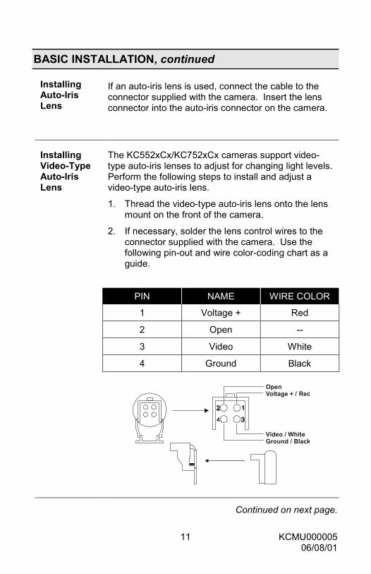
InstallingAuto-IrisLens
If an auto-iris lens is used, connect the cable to theconnector supplied with the camera. Insert the lensconnector into the auto-iris connector on the camera.
InstallingVideo-TypeAuto-IrisLens
The KC552xCx/KC752xCx cameras support video-type auto-iris lenses to adjust for changing light levels.Perform the following steps to install and adjust avideo-type auto-iris lens.
1. Thread the video-type auto-iris lens onto the lensmount on the front of the camera.
2. If necessary, solder the lens control wires to theconnector supplied with the camera. Use thefollowing pin-out and wire color-coding chart as aguide.
PIN NAME WIRE COLOR
1 Voltage + Red
2 Open --
3 Video White
4 Ground Black
Open Voltage + / Red
Video / White Ground / Black
Continued on next page.

12 KCMU00000506/08/01
BASIC INSTALLATION, continued
3. Plug the connector into the auto-iris lens jack onthe front of the camera. The connector is keyedand can only be inserted into the jack one way.
InstallingVideo-TypeAuto IrisLens,continued 4. Make sure that the E/I switch located on the back
of the camera is set to OFF.
5. Apply power to the camera.
6. Adjust the focus ring on the lens for an optimumpicture. If the picture is not visible, set the lens forproper exposure by adjusting the ALC (automaticlevel control), and LEVEL on the lens. The ALCsetting can range between AVG (average) or PK(peak). An AVG setting is appropriate for mostapplications.
AdjustingALC
AVG – To slow the reaction of the lens to changinglight, set the range on the AVG setting to average thevideo level from the camera. Use this when there arebright spots in the picture, such as lights or glare fromthe sun.
PK – To increase the speed of the lens reaction to thechanging light, set the lens adjustment to PK so thelens will adjust to the brightest or peak object in thevideo. Use this setting if you want to see the brightestobject and not the background objects.
AdjustingLevel
Adjust the Level control for the best picture during theday. A night adjustment may not provide the propersetting for controlling the light during the day.
1. Set the back-focus of the camera before the finaladjustment of the video level. (See the section onBack-focus Adjustment later in this manual.)
Continued on next page.

13 KCMU00000506/08/01
BASIC INSTALLATION, continued
AdjustingAGC
1. If the auto-iris has a gain adjustment, perform thefollowing steps:
a. If the lens oscillates between open andclosed under bright lights, slowly turn the gainadjustment counterclockwise until theoscillating stops.
b. Increase the light getting to the camera byadjusting the level control and readjusting thegain control as necessary.
InstallingDC-TypeAuto-IrisLens
The KC552xCx/KC752xCx cameras support DC auto-iris lenses. Perform the following steps to install andadjust a DC-type auto-iris lens.
1. Thread the DC iris lens onto the lens mount onthe front of the camera.
2. If using an Ultrak lens, skip to step 4.
3. If using a non-Ultrak lens, use the manufacturer’sinstructions to solder the connector that comessupplied with the camera to the lens control wires.The pin-out and wire color-coding for DC-typeauto-iris lenses can vary from one manufacturer toanother.
4. Plug the connector into the DC iris jack on thefront of the camera. The connector is keyed andcan only be inserted into the jack one way.
5. Make sure that the E/I switch located on the backof the camera is set to OFF and the A/I switch isin the DC position.
6. Apply power to the camera.
7. Adjust the DC-type auto-iris lens for an optimumpicture using the IRIS LEVEL control on the backof the camera.

14 KCMU00000506/08/01
BASIC INSTALLATION, continued
AdjustingManual IrisLens
A manual iris lens is used in indoor applications wherelighting from windows can considerably affect the lightlevel of the room. When using the manual iris lens,perform the following steps:
1. Set the E/I switch to ON.
2. Turn the iris ring on the lens to the fully OPENposition.
3. Focus the lens to obtain optimum picture.
4. To increase the camera’s depth of field, slightlyclose the manual iris by approximately five to tenpercent.
Routing theCable
Route the video cable from the monitor location to thecamera location.
WARNING: Care should be taken when routingthe cable from the monitor to the camera. Try notto put unnecessary strain on the cable orconnectors. Do not place the cable next tofluorescent lights as interference may result. Donot use staples to support the cable as they maydamage the cable. If the provided camera cableis not long enough, do not substitute a telephonecable as it could damage the camera and/or themonitor. Contact your authorized Ultrakrepresentative to purchase longer cables.
Continued on next page.

15 KCMU00000506/08/01
BASIC INSTALLATION, continuedConnectingthe Cable
1. Plug the cable into the BNC output connector portlabeled VIDEO OUT located on the back of thecamera.
2. Plug the other end of the cable into thecorresponding video input port on the back of theobservation monitor.
1. Connect a two-conductor power cable to the 24Vac input port located on the back of the camera.
Instructionsfor 24V acModels
24V ac Class 2
G~ ~
Use a UL-listed Class 2 powertransformer and a 24V poweradapter. Use only a Class 2power source.
2. Apply 24V ac power to the camera.
Instructionsfor 230V acModels
1. Plug the power cord into a wall outlet.
2. Apply 230V ac power to the camera.
3. Plug the monitor’s power cable into a suitable walloutlet.
4. Turn on the monitor’s power switch(es). Themonitor should display images for the connectedcamera(s). For more information on systeminstallation and camera display options, refer tothe observation monitor or system manual.
5. Adjust the camera back-focus, lens focus, and iriscontrols for an optimum picture.
Continued on next page.

16 KCMU00000506/08/01
BASIC INSTALLATION, continued
Back-focusAdjustment
Although the camera lens was back-focused by themanufacturer prior to shipping, it may be necessary tomake modifications.
For best results, perform back-focus adjustments atnight or while using a #6 or #8 welder’s glass in frontof the lens. The focus of the camera could changeslightly if the camera iris is adjusted when focused ona light scene, which then changes to a dark scene.However, the camera will remain in focus if thecamera is adjusted when focused on a dark scene,which then changes to a lighter scene.
To make back-focus adjustments, perform thefollowing steps:
1. After mounting the lens on the camera, applypower.
2. If a picture is visible, focus on the scene. If apicture is not visible, open the iris on the lens.Open the lens as wide as possible by placing awelder’s glass in front of the lens.
3. When the iris is open to the widest point, readjustthe focus for a clear picture. If a clear picture isnot visible, set the focus ring to midrange.
4. Loosen the back-focus lock screw.
Back-focus Screw
Back-focusAdjust Ring
Continued on next page.

17 KCMU00000506/08/01
BASIC INSTALLATION, continued5. Adjust the back-focus ring for a clear picture.
6. Tighten the back-focus lock screw.
7. Fine-tune the focus with the focus ring on thelens.
8. Remove the welder’s glass from the front of thelens.
9. Adjust the level control of the lens for the bestpicture quality
AdjustingBack-focuson ZoomLens
The objective of back-focusing a zoom lens is similarto that of a fixed-focal length camera, except that theback-focus is also adjusted to maintain the focuswhen zooming the lens in and out of a scene. Forzoom lens back-focus adjustment, perform thefollowing steps:
1. Choose an object at the farthest range that youwish to look at with a zoom lens.
2. Make sure that the iris of the lens is wide open.For best results, make the adjustment by using a#6 or #8 welder’s glass placed in front of the lens.
3. Adjust the focus to stop on the far range.
4. Adjust the zoom on the lens to obtain the widestpicture.
5. Loosen the back-focus lock screw.
6. Adjust the back-focus ring for the clearest picture.
7. Adjust the zoom on the lens to the far telephotoposition.
8. Adjust the back-focus ring for the clearest picture.
9. Adjust the zoom on the lens back to the widestpicture.
10. Readjust the back-focus for the clearest picture.
Continued on next page.

18 KCMU00000506/08/01
BASIC INSTALLATION, continued11. Tighten the back-focus lock screw.
12. Repeat the previous steps as many times asnecessary to maintain a clear picture through theentire zoom range.
IMPORTANT: Verify that the camera remains infocus after tightening the lock screw. Onoccasion, tightening the lock screw can cause thecamera to be slightly out of focus.

19 KCMU00000506/08/01
SECTION 3:TROUBLESHOOTING AND PREVENTIVE
MAINTENANCE
TROUBLESHOOTING
If problems occur, verify the installation of the camera with theinstructions in this manual and with other operating equipment. Isolatethe problem to the specific piece of equipment in the system and referto the equipment manual for further information.
PROBLEM CHECKThere is no power. • Make sure the system is plugged
in.
There is power butno picture.
• Verify power to all pieces ofequipment in the system (cameragreen LED on).
• Check video and DC drive switchposition.
• Verify that the video cables areconnected correctly.
• Verify that the lens cap has beenremoved from the lens and thatthe iris of the lens is open.
The video is toodark.
• Adjust the iris and check A/Iconnections.
There is video, butno control.
• Power down the system for oneminute.
• Then turn the power back ON.

20 KCMU00000506/08/01
PREVENTIVE MAINTENANCE
Following the preventive maintenance scheduleallows detection and correction of minor faults beforethey become serious and cause equipment failure.
Every three months, perform the following:
1. Inspect all connecting cables for deterioration orother damage.
2. Clean components with a clean damp cloth.
3. Verify that all the mounting hardware is secure.
21 KCMU00000506/08/01
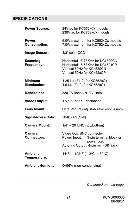
SPECIFICATIONS
Power Source: 24V ac for KC552xCx models230V ac for KC752xCx models
PowerConsumption:
6.0W maximum for KC552xCx models7.0W maximum for KC752xCx models
Image Sensor: 1/3” color CCD
ScanningFrequency:
Horizontal 15.75KHz for KCx520CNHorizontal 15.63KHz for KCx52xCPVertical 60Hz for KCx520CNVertical 50Hz for KCx52xCP
MinimumIllumination:
1.25 lux (F1.2) for KC552xCx1.6 lux (F1.2) for KC752xCx
Resolution: 330 TV lines/470 TV lines
Video Output: 1 Vp-p, 75 Ω, unbalanced
Lens Mount: C/CS-Mount (adjustable back-focus ring)
Signal/Noise Ratio: 50dB (AGC off)
Camera Mount: 1/4” – 20 UNC (top/bottom)
CameraConnectors:
Video Out: BNC connectorPower Input: 3-pin terminal block or
power cordAuto-iris Output: 4-pin mini-DIN jack
AmbientTemperature:
14°F to 122°F (-10°C to 50°C)
Ambient Humidity: 0~96% (non-condensing)
Continued on next page.

22 KCMU00000506/08/01
SPECIFICATIONS, continued
Dimensions: 2.4W x 2.1H x 5.5D in(62W x 54H x 140D mm)
Weight: 24V ac Models – 14.9oz (425g)230V ac Models – 21.2oz (605g)
NOTE: If used continuously, be sure to operate attemperatures less than 40°C (104°F) for long-termstable performance.