
Ultra-wideband transmit/receive antenna pair for ground penetrating radar
5
Ultra-wideband transmit/receive antenna pair for ground penetrating radar E.S.Eide Abstract: Exp~rinient~il results from a iiovcl compact transmillrcceive antenna pair consisting of two loss-loaded how-tic monopole antennas are described. Instead or using a distributed resistive loading of the aiitciiiiii, a broadband iiiicrowave absorber is applied as a lossy diclcctric loading or [he bow-tic clciiients. The antcnna pair lias a numbcr of remarkable Teattwx It is characterised by a high bandwidth (400-6000MHz), a low cross-coupling, aiitl a sharp impulse response with low reverberation, Tlic radiation piittern niaintains Llic Same shape and oricnlation across the whole bandwidth, with an E-plane beamwidth ranging kom 100" to 40" and ii niiixiniuni antenna gain of - 3.0dRi. The input impctlirncc is rcsistivc, and lids a valuc of 75Q ovcr a wide f'rcquency range. Furthermorc. tlic input inipcdancc is not al'fcctcd by tlie prcsciicc of the soil wlicii tlic antenna is placed 011 the ground stdacc. 1 Introduction Ground penclrating radars (GPRs) are designcd to operate ovcr a wide frcqucncy range, typically froin ti few MMz up to 3GHz. They norni;dly operate either in a pulsed mode or a stepped-hcquency conliniious-wave modc (SFCW), with Lhc iintennas close Lo or in contact with tlie gvoiind for nuximuin penetration into the soil. I Tencc, in ii ground penclrating radar systcin, Lhc antenna is R crilical coinpo- iient boll1 Trom a systeiii pcrfcirmaiicc md an image recoii- slriiction point or view. An ullra-wideband GPR requires anleiinas with the widest possible bandwidth to exploit lhc niaxiniiini Lime domain resolution of the vadar syslcm. The time domain performancc of a GPR antenna is a critical rcquirenicnt sincc the target echo iirl.ivcs a Sew nnnoscconds al'lcr the end of' tI.ansmission. The anlcniiii should tlicrcforc radiate a sharp piilsc with low reverberation (ring-down) to avoid masking of' targel ecliocs. The effects of rangc sidelobes from antenna ring-down are analysed hy Noon and Stickley [I] in tcrins of the initcniiii'~ Q-factor. The handwidlh rcquircmcnt applies both to the impedancc and the radiatioii cliiiractcristics, Impedancc varialions over tlic frequency ningc are often causcd by multiple rcflcctions l'rom different parts of tlic anlciina structure, and the rcsulting ringing tlcgradcs the antclilia pcrformancc. The forward transfer fimction of a well dcsigncd GPR antcnna should Lhercfore liiivc as litlle ripple as possible. For GPR antennas it is coninioii practice to use loss loiiding to reduce tlie anlcniials Q-factor and iiicrciisc the bandwidth. By propcr loading, a n;irrowhand dipolc antcnnii cm he transformed into a widcband tr;ivelling wiivc antenna with a pure outward tr;ivclling wave. In their classical paper, Wu and King [2] dcrive a continuous load- ing profile for a dipole antenna, where the resistancc R(z) is incrcascd along tlic dipole iirm: Hcrc, 2/17 is tlie relative position along the dipole win with length h, 11" = v'p0/q,, and 'I$, is ~lic complcx cxpwision paniniclcr discussed in 121. The currcnl distribotion and the Ihr-licld time response of the Wu-King dipoles and vcc- aiilciiniis were calciilated nunicrically hy Rose and Vickers [9 showing a Lime response with no inultiplc rcflcctions from the ends of the antennas. Montoya and Smith [4] sludied the pulse radiation horn difl'crcnt lmidcd inono- poles using the fink-difTercncc lime-domain (FDTD) method. Propertics like feed point reflections, mdiiition ch. r~~ricterisLics, .I lime domain gain, pulse syninictry and fidelity oT the radiated pulses were compared (or different loading proliles. Thc conclusions were that the Wu-King profile performs hcst for pulse radiation, cvcn if tlie radia- tion efficiency for a Wu King antcnna is as low as 1040%~ The traditional antenna configuriition for GPR has bccii to use scparalc iintennas for transniissioii and rcccplion to obtain sufficient isnlatioii betwccn tlic transmitter and the receiver. Typically, resistor loaded dipoles, spiral anlenilas or double-ridged horn iintennas lvive been used for this lpurpose. TEM lionis and vce-dipoles liiive also bccn suc- antenna coiifigurations give a bistatic radiir system that is disadvantageous for incar rangc imaging of shallow targets. Urown and Woodward [7] gave an cxperimcntal paper on bow-tic dipolc anleiinas in 1952. Tliesc antennas hiivc become very popular for GPR and widcband piilscd appli- catioiis, and they have been optimised for broadband pulse radialion using resistive loading [8]. A theoretical iinalysis of the input impcdiince of how-tie dipoles lias recently bccn carried out by Lcat CI U/. [O] using tlic nicthod of mornents. Even if this paper docs not talc tlic loss-loading into ~icccii~nt, it is sliowii that increasing tlie flare angle of the bow-tie reduccs both tlic peak valuc ol'thc input rcsisknicc ccssl'nlly adopted Tor GPR applications [5, h]. All tlicsc 23 I
Transcript of Ultra-wideband transmit/receive antenna pair for ground penetrating radar

Ultra-wideband transmit/receive antenna pair for ground penetrating radar
E.S.Eide
Abstract: Exp~rinient~il results from a iiovcl compact transmillrcceive antenna pair consisting of two loss-loaded how-tic monopole antennas are described. Instead or using a distributed resistive loading of the aiitciiiiii, a broadband iiiicrowave absorber is applied as a lossy diclcctric loading or [he bow-tic clciiients. The antcnna pair lias a numbcr of remarkable Teattwx It is characterised by a high bandwidth (400-6000MHz), a low cross-coupling, aiitl a sharp impulse response with low reverberation, Tlic radiation piittern niaintains Llic Same shape and oricnlation across the whole bandwidth, with an E-plane beamwidth ranging kom 100" to 40" and ii niiixiniuni antenna gain of - 3.0dRi. The input impctlirncc is rcsistivc, and lids a valuc of 75Q ovcr a wide f'rcquency range. Furthermorc. tlic input inipcdancc is not al'fcctcd by tlie prcsciicc of the soil wlicii tlic antenna is placed 011 the ground stdacc.
1 Introduction
Ground penclrating radars (GPRs) are designcd to operate ovcr a wide frcqucncy range, typically froin ti few MMz up to 3GHz. They norni;dly operate either in a pulsed mode or a stepped-hcquency conliniious-wave modc (SFCW), with Lhc iintennas close Lo or i n contact with tlie gvoiind for nuximuin penetration into the soil. I Tencc, in ii ground penclrating radar systcin, Lhc antenna is R crilical coinpo- iient boll1 Trom a systeiii pcrfcirmaiicc md an image recoii- slriiction point or view. An ullra-wideband GPR requires anleiinas with the widest possible bandwidth to exploit lhc niaxiniiini Lime domain resolution of the vadar syslcm. The time domain performancc of a GPR antenna is a critical rcquirenicnt sincc the target echo iirl.ivcs a Sew nnnoscconds al'lcr the end of' tI.ansmission. The anlcniiii should tlicrcforc radiate a sharp piilsc with low reverberation (ring-down) to avoid masking of' targel ecliocs. The effects of rangc sidelobes from antenna ring-down are analysed hy Noon and Stickley [ I ] in tcrins of the in i tcni i i i '~ Q-factor. The handwidlh rcquircmcnt applies both to the impedancc and the radiatioii cliiiractcristics, Impedancc varialions over tlic frequency ningc are often causcd by multiple rcflcctions l'rom different parts of tlic anlciina structure, and the rcsulting ringing tlcgradcs the antclilia pcrformancc. The forward transfer fimction of a well dcsigncd GPR antcnna should Lhercfore liiivc as litlle ripple as possible.
For GPR antennas it is coninioii practice to use loss loiiding to reduce tlie anlcniials Q-factor and iiicrciisc the bandwidth. By propcr loading, a n;irrowhand dipolc antcnnii c m he transformed into a widcband tr;ivelling wiivc antenna with a pure outward tr;ivclling wave. In their
classical paper, Wu and King [2] dcrive a continuous load- ing profile for a dipole antenna, where the resistancc R(z) is incrcascd along tlic dipole iirm:
Hcrc, 2/17 is tlie relative position along the dipole win with length h, 11" = v'p0/q,, and 'I$, is ~lic complcx cxpwision paniniclcr discussed i n 121. The currcnl distribotion and the Ihr-licld time response of the Wu-King dipoles and vcc- aiilciiniis were calciilated nunicrically hy Rose and Vickers [9 showing a Lime response with no inultiplc rcflcctions from the ends of the antennas. Montoya and Smith [4] sludied the pulse radiation horn difl'crcnt lmidcd inono- poles using the fink-difTercncc lime-domain (FDTD) method. Propertics like feed point reflections, mdiiition ch. r~~ricterisLics, .I lime domain gain, pulse syninictry and fidelity oT the radiated pulses were compared (or different loading proliles. Thc conclusions were that the Wu-King profile performs hcst for pulse radiation, cvcn if tlie radia- tion efficiency for a Wu King antcnna is a s low a s 1 0 4 0 % ~
The traditional antenna configuriition for GPR has bccii to use scparalc iintennas for transniissioii and rcccplion to obtain sufficient isnlatioii betwccn tlic transmitter and the receiver. Typically, resistor loaded dipoles, spiral anlenilas or double-ridged horn iintennas lvive been used for this lpurpose. TEM lionis and vce-dipoles liiive also bccn suc-
antenna coiifigurations give a bistatic radiir system that is disadvantageous for incar rangc imaging of shallow targets.
Urown and Woodward [7] gave an cxperimcntal paper on bow-tic dipolc anleiinas in 1952. Tliesc antennas hiivc become very popular for GPR and widcband piilscd appli- catioiis, and they have been optimised for broadband pulse radialion using resistive loading [8]. A theoretical iinalysis of the input impcdiince of how-tie dipoles l ias recently bccn carried out by Lcat CI U/. [O] using tlic nicthod of mornents. Even if this paper docs not talc tlic loss-loading into ~icccii~nt, it is sliowii that increasing tlie flare angle of the bow-tie reduccs both tlic peak valuc ol'thc input rcsisknicc
ccssl'nlly adopted Tor GPR applications [5, h]. All tlicsc
23 I
and tlie reactive part ol'tlic input inipcdancc Also, current- density plots i n 191 show that most ol' the current flow occurs at tlic edges of the how-tics. Rcwntly, the FDTD method l i as been used by Hagness el d. [ IO] to opliinise tlic resistive loading of bow-tie antcnnes with ultra-low rcvcr- hcration For biomedical imaging [ I I]. Their restilts show that the end reflection ctiii be siipprcsscd by a s iniicli a s IO6 dB rclativc to the exciting pulse. Resistor-loaded bow-tic anleiinas covered with lerritc-coated cavities have also hecn reported [ 121. I t was found that the iinpcdancc chanicteris- tics of tlie GPR antennas were improved to some extent by using ferritcs in the cavity. Howcvcr, the impulse response was degraded and the undesircd radiation into air was increased by the introduction of l'crrites i n the cavity, and the ferrite-loading was therefore not succcs~iil in tliis design.
In this paper we suggcst a constcllatioii of two loss loaded how-tic monopole antennas to ohlain a coinpact quasi-monostatic antciina struclurc. This gives a livourablc geometry that simplifies tlic short range l'ocusing ol' tlie
also eliminates the nccd Cor broadband baluns in llic antcnna feed systein.
2 Antenna design
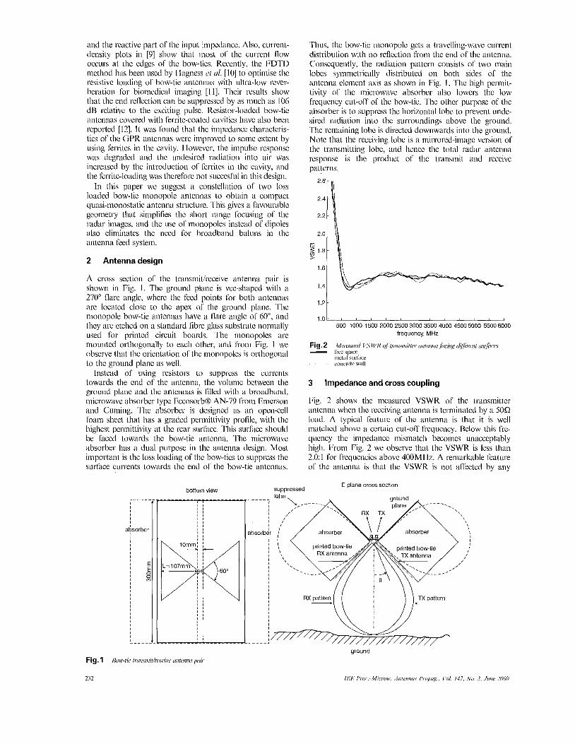
A cross section ol' the Lransniitlrcceive anteniia pair is shown in Pig. I. The ground plane is vcc-shaped with ii
270" flare angle, whei-c the feed points Cor both antennas arc localcd closc to the apex ol' the ground plane. The monopole bow-tie antcnnas have a flare angle ot 60", and they tire etched on a standard librc glass substrate normally used for printed circuit boards. The monopolcs arc mountcd orthogonally to each other, and from Fig. I we observe that tlic orienlation 01' the inonopoles is ortliogoniil to the ground plane as well.
Instead of nsing resistors to suppmss thc currciits towards tlie end of the iinlcnna, the volunic bctwecn the ground plane and the sintcinias is fillcd with ii hroadband, niicrowavc absorber type EccosorbO AN-79 l'roin Emerson and Cuniing. 'l 'lie absorber is designed a s an oIxwcell foam sheet that l i i is a graclcd permittivity profile, with tlie highest pcrinitlivity ill the rear siirlhce. This surllcc should he liiccd towards the bow-tic antenna. 'The niicrowavc absorber l i i is a dual purpose i n tlic antenna design. Most important is the loss loading ot'thc how-tics to suppress the surfice currents towards the end 01' the bow-tie antennas.
I) d. '11 . images, ' iiiid the nse ol'nionopoles iiistcad ol' dipoles
bottom view 71.' absort
Thus, tlic bow-tie monopole gets a travclling-wave current distribution with no rcflcction from t l ie end ol' tlic antenna. Consequently. the radiation pattern consists of two maiii lobes symnietl-ically distributed on both sides of tlie aiitcniiii clciiient axis 21s shown in Fig. I . 'The high permit- tivity of tlic microwave absorber also Iowcrs the low frequcncy cut-oft' of l l ic how-tic. The other purpose of the absorber is to stipprcss tlic liorizoiital lohe to prevent unde- sired I-adiation into the surroundings above the ground. The remaining lobc is directed downwards into the ground. Note that the receiving lohe is a mirrored-image version 01 the transmitting lobc, and liencc the total ~ i d a r antenna response is the product of tlie transmit and receive p"tlcrlis.
1.21
l . o l - ~ l ~ l ~ L ~ ~ ~ l ~ I 500 1000 1500 2000 2500300035004000 45005000 55006000
frequency, MHr
Meirstwd V.SM//< q/ oiiii.smiit<,i or ien i io /wi ,g d ~ i w ~ i ro$i.1;...~
l l l C l i l l ml:,ce . ~ C o l l C m t C w a l l
Fig. 2 - iice SIlaCC
3 Impedance and cross coupling
Fig. 2 shows the nicasurcd VSWK ol' the tl.ansinittcr antenna when the receiving anlcniia is tcrminiitcd by a 5 0 0 load. A typical l'eatiii-c ol' tlic iintennii is that it is well matched above ii certain cut-OK licqucncy. Below this fie- qiiciicy the impedance inisinateh becomes unacceptably high. From Fig. 2 wc observe that the VSWR is less than 2.0: 1 for l'rcquencics above 400Ml-lz. A remarkable fwture of Lhc anlcnnii is that the VSWR is not affected by any
E~plans cross section suppressed

nxitcrial t1i;it is brought iii front of the i intcniid. Fig. 2 shows 110 signif i~int cliaiige of tlic input iinpcdiincc wlicn the antenna is l'acctl towards ii nickl surface and a concrctc wall. This is ii very iiseful fcaturc of a GPR ~nileiiiiii, sincc the sliorl-rangc image qiiality i s noi-m;illy degrtidcd by thc variations ol' thc antennii impedance :is tlic i i i i teni i i i is moved along tlic grwiid. The cxplanation or this fcaturc is 11iat only the ends of the how-tie elements arc closc to tlic surface 01' the ground. The lo:iding ol' the clctncnls causcs tlic current density to be low at t l ic ends or the how-tics, and conscquently tlicrc is iio strong near-field iit tlic ends of the how-tics that niighl be sensitive to tlic itcarby nicdiuni.
leal C 150
OIL-', " " " " " '
imaginary
-loo ' '5d0 I000 1560 2000 2500 3000 3560 4000 4500 5dOO 55b06000
frequency, MHz b
Fig. 3 - lo;,'lcil R d ,er/ i ~ w ~ , ~ i ~ o /xiri,i oflww/l~, umwm iyui itrr/inimap
Lillloi,tlctl
The I-cal and iiiiagin;iry parts of the input impcdancc for the antcnna, with and without tlic absorbing loading, lire compared in Fig. 3. For the loiided vcrsion of tlie antenna the input impcdancc bccomcs resistive with ii v~iluc close to 75Q, cxccpt Ibr low l'rcq~~cncics wlicrc the inipcdsncc approaches inlinity. The unloadcd iintciiiiii lias 2111 iniped- ailcc hcliaviour that corresponds well with the restilts reported by Li ei d. [13]. Note that tlic avc~ ige inipcdancc of t l ie monopole antcnna is hall' tlic iiiipc~liincc of ii dipole antenna. N iiiiierical siiiiiiliitioiis or the iniped;incc ol' iiii
unloaded bow-tic dipole i i~itci inii 1141 confirm that the impedtincc spii-als towards it pucely rcsistivc impedancc of I520 as tlic Srcquency is incrc;iscd. Hencc, wc conclude that thc absorbing loading used in the iiionopolc antenna gives ii good supprcssion ol' the end reflections since h e impcdancc rciiiiiins almost co~is t~ i i i t over a wick l'rcqucncy range. t'roni Fig. 2 we ciiii derive lhe l'ollowing empirical
tiritema/;,, wlicrc tlic VSWR is giwitcr t l i t i i i 2.0: I expression Tor tllc antentxi's low ficqucncy cut-oK ol' tlic
I lere, ( I is tlic vclocity ol' light i t i frcc spicc, m d L is tlic Icngtli ol' tlie bow-tic. Thc diclcctric loading finni tlic niicrowavc ahsorhcr iiicruiscs the electrical length ol' the iintenna, and hence rcduccs the IOW l'rcqucncy cut-ofl' coni- pared to tlic unloaded zi~itcntia.
The cross coupling hctwccn the triinsmil~cr and receiver ~intciina was mcasured hy a F11'8753E network analyscr over tlic fiequciicy range I MHz l o 6Gtls. Thc diagi-ani in Fig. 4 shows that thc isolation bclwecn the transmil md reccivc iintennas is better than 2SdH Tor ficqucncics above 500MHz. This relatively high isolation is due to t l ie orthog-
oiiiil mounting of the antennas. At 100M Hr l l ic cross coupling incrc~iscs by I O d H , iind t l i is might be diic to a resonant behaviour of tlic wliolc antcnna structurc includ- ing the finite-length ground plaiic.
- l o t
-35 -40 Ld 500 1000 1500 20002500 3000350040001500500055006000

quency. These plots show that both the E-plane and fl- plane radiation pattcrns maintain a stable shape and oricn- talion over 21 widc frequency range. If no loss lading is applied, the radiation pattcrns wiry much more with tlic frequency because the antenna current distribution in this case differs kom a travelling wavc. Note that thc anechoic chamber used for the tests was dcsigned for frcquencics above 2GHz, and therefore reflections from the walls are present at frequencies below this frequency.
The antenna transfer function was nieasurcd over the kc- qucncy range lMHz to 6GMz at an outdoor antenna range. By properly calibrating the nelwork analyser and taking the cable and free space losscs into account, we arc able to compute [he antenna gain a1 various frcquencies. An estimate of the imtcnnii gain can he c;ilculated using Friis' transmission cqoation
I ( m e a s ~ i r e d ) [ ~ ~ ~ ~ ~
= G q m l + G R ~ ~ I + 1 0 1 ~ (4:J - 0) where Cy. and GI< represent the antenna gains of the trans- mitter and receiver aiitennas, rcspectively, and the free space loss is given by the wavelength A and the distance R. Assuming equal gains of the two initennas wc obtiiin
G[,in] = G T [ ~ I = Giqml
Time domain processing was applied to remove multipath reflections from Ihe mcasured dah. An estimate of lhe borcsight antenna gain (transfer runclion) is plotted i n Fig. 7. We observc that the gait1 increases from -6dBi at SOOMHz to a maximum of-3dBi at 4.2GIiz. At 800Mllz the gain drops to -8.5dBi. This phenomenon is coincident with a similar drop in tlic TiR-isolation (Fig. 4) and varia- tions in the input impedancc (Fig. 3). The rapid changes of the antenna diagram at 800MkIz in Figs. 5 and 6 indicate that a mode transition occurs in the antenna current distri- bution at Ibis frequency, The rapid roll-off a1 frequencies below 500MHz can be explained by the increasing imped- ance mismatch at these frequencies.
-"' ' 5d0 lo00 1500 2000 2 j O O 3000 3500 4000 4400 50005500 frequency, MHz
Fig. 7 lis~imuieri lhrc.~i~/i t wrenna xniri
The half-power beamwidths in the E-plane and H-plane were estimated from the normalised radiation patterns, and Fig. R shows plots of these estimates. We observc that the E-pkmc main lobe width varies rrom approximately 100" at
234
400MIIz to 40" at 3.5GHz. Above lGHz thc If-plane pattern has a IialFpower beamwidth of 70". Below lGHz bolh patkrns become wider, but the mcasured results are inaccurate at low frequcncies due to rctlcctions from the anechoic chambcr.
1601
2ot 01 500 1000 1500 2000 2500 3000 3500
frequency, MHr
Fig. 8 li-~ilwx~ mil &i/hx, I u ~ - p w e i . /wmdt /u
H-pliiiic ~~ &pl2iX,C
The imtenna clliciency am be estimated by calculating the directivity rrom tlic approximate Carmula [3]:
where 0,: and 6111 are the half-power beamwidths (in dcgrees) in the E-plane and Il-plane, respectively. Using the relation
gives an approximate antenna eficicncy 7 - 5. This is a rather low antenna efficiency, but oti the other hand, niost GPR antenna l~ ive an efficiency of the s" order due to the loading of the elements.
-1 O I 0 rl -201 I i

suppresscd by 30tlU. Tlicsc t i m delays correspond to pos- sible difl'ractions from i h c ends o f tlie apex of the ground plane and difkaction from the end 01' the bow-lie anienn;~. These reverbcralions may he furlher suppressed by resistor loading of tlic bow-tic anleiinii clcnienl and the addition 01' absorbers to i l i c apex region of (he ground plane.
Nole that using the band-limited li.cc~uciicy range from 400-6000MI Ir gives a hctlcr iinpiilse responsc than i h e rccspo~isc from the liill bandwidth down to DC. In a SFCW radar sysiein we liavc [lie flexibility Lo defnc precisely tlie limits ol' llie iriinsmitted frequciicy band, iis opposcd to g i n
irnpulsc radar wliere the impulsc contains all spcctrtil componcnts. Impulsc excilation would require a11 anlennii s t r u c ~ i ~ ~ o that has a shunt loading to cnsurc sufficicnl impedance match down to UC. On the other hand, a inoiiocycle pulse excitation like tlic zcro-DC Gaussian pulse w~ iu ld give H better time donxiin pcribrniancc. Fig. 10 shows ;I GPR inuige of a iiictiil cylinder and ii dihcdral rctlcctor buried in dry sand iii a laboratory sand- hox. The imagc was tal ic~i with the how-tic iiiitcn~iii pair elevated 37an ahovc tlic sand surlise, using ii stcpped- l'reqtlctxy waveform with l'rccpcncics from SOOMHI to 3400MHz. The TiK-leakage is iiiiicli stronger tliiiii the target cchocs, and it is tlicrcforc subt~icted from t l ic received signal to enhance i l i c target ccliocs. The dala iii Fig. 10 are displayed a s tlic rail valiic 01' the i-cceivctl echoes, where thc black and white coloiirs corrcspond to positive and negative voltages, rcspcctivcly. We observe ilia1 130th the sand surfiicc and thc huricd iargcts appear without multiple echoes.
0
1
2
3
1 m
5 5
8 6
7
6
9
-
"0 025 0.50 0.75 1.0 L25 1.50 1.75
i
0 4
06
0 8
1 0
6 Conclusions
An ultl.ii-wklchand bow-tic monopole iransniitircccive iiiitcnna conliguration cspecially designcd for ground pcnc- traling radar has been described. l l ie iintcniiii conlignra- tion has several advanlagcs compiired LO traditional pairs of dipoles used l'or ground peiiciraling riidars: (i) Tlic use ol'inoiiopoles gives ii very compact antcnna pair with properties closc i o ii inonostalic radar gccometsy. (ii) The use of nioiiopolcs elimiiiales the need for a 1x11. anccd to unbalanced (halun) transfornicr that oltcn limits the baodwidlh of tlic iinteiina system.
(iii) The anlcnna l i t is ultra-widcband pcrformance due Lo the lossy loading from the absorbers. The radialion effi- ciency is low coinpiircd i o ii siinilar iinloadcd antcnna, hut Ihr a GPR, ii slinrp impulse rcspoiisc with low revcrbcra- t ion is ol' higher imporlance tliiin tlic aritenna giiin. The I.adiation I'iitlerii is well &lined across lhc wliolc frcquency band willi the tilain lobe dircctcd towards tlic ground. (iv) The input impedancc is almost unaffcctcd hy the ground mcdiuni. The iinlci~iia produces sharp time domain GI'R images 01' shsllowly buried targets. The antenn~i design docs not use resistor loading or the bow-tics, and lurllicr improvement or the impulse ~-csponsc would tIicrcI'orc be possible using Lliesc tcclniiqucs. Further rcsc~irch niay also iiivolve optimisalion of the how-tie flare angle iind clcinenl shape for niaxiinum bandwidlli per- sllrmancc.
7 Acknowledgments
The ;iuthor wislics to thank Dr .Ion Andcrs Aas a1 the Norwcgian University of Science and l'cclinology for help- ful and Ij.iiit(iil discussions.
8 References
235