Ultrasonic atomizing transducer/ultrasonic transducer/piezoelectric transducer
page 1 - 2017-08-31 Precision – Innovation www.danisense.com
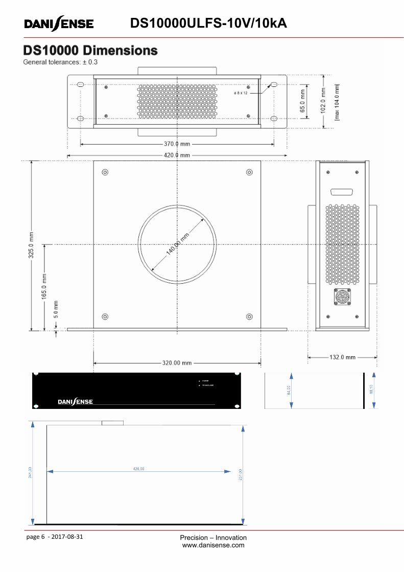
DS10000ULFS-10V/10kA
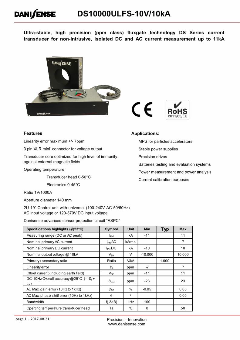
Features
Linearity error maximum +/- 7ppm
3 pin XLR mini connector for voltage output
Transducer core optimized for high level of immunity
against external magnetic fields
Operating temperature
Transducer head 0-50°C
Electronics 0-45°C
Ratio 1V/1000A
Aperture diameter 140 mm
2U 19” Control unit with universal (100-240V AC 50/60Hz)
AC input voltage or 120-370V DC input voltage
Danisense advanced sensor protection circuit “ASPC”
Ultra-stable, high precision (ppm class) fluxgate technology DS Series current
transducer for non-intrusive, isolated DC and AC current measurement up to 11kA
Applications:
MPS for particles accelerators
Stable power supplies
Precision drives
Batteries testing and evaluation systems
Power measurement and power analysis
Current calibration purposes
All ppm (or %) values refer to nominal current 7500A or 10V
Specifications highlights (@23⁰C) Symbol Unit Min Typ Max
Measuring range (DC or AC peak) IPM kA -11 11
Nominal primary AC current IPN AC kArms 7
Nominal primary DC current IPN DC kA -10 10
Nominal output voltage @ 10kA VSN V -10.000 10.000
Primary / secondary ratio Ratio V/kA 1.000
Linearity error ƐL ppm -7 7
Offset current (including earth field) VOE ppm -11 11
DC-10Hz Overall accuracy @25°C (= ƐL +
IOE )ƐDC ppm -23 23
AC Max. gain error (10Hz to 1kHz) ƐAC % -0.05 0.05
AC Max. phase shitf error (10Hz to 1kHz) q ⁰ 0.05
Bandwidth f(-3dB) kHz 100
Operting temperature transducer head Ta ⁰C 0 50
page 2 - 2017-08-31 Precision – Innovation www.danisense.com
DS10000ULFS-10V/10kA
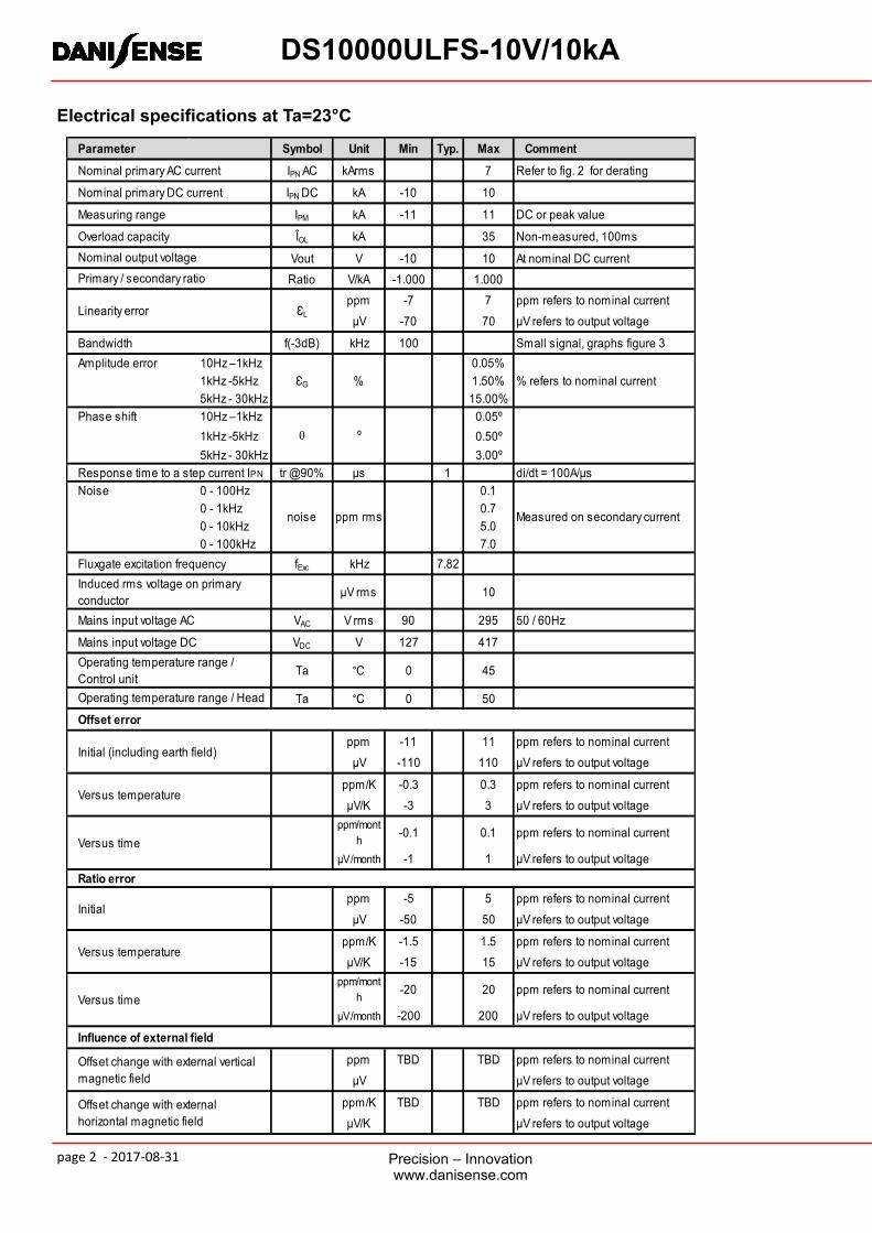
Electrical specifications at Ta=23°C
Symbol Unit Min Typ. Max Comment
IPN AC kArms 7 Refer to fig. 2 for derating
IPN DC kA -10 10
IPM kA -11 11 DC or peak value
ÎOL kA 35 Non-measured, 100ms
Vout V -10 10 At nominal DC current
Ratio V/kA -1.000 1.000
ppm -7 7 ppm refers to nominal current
µV -70 70 µV refers to output voltage
f(-3dB) kHz 100 Small signal, graphs figure 3
Amplitude error 10Hz –1kHz 0.05%
1kHz -5kHz 1.50%
5kHz - 30kHz 15.00%
Phase shift 10Hz –1kHz 0.05º
1kHz -5kHz 0.50º
5kHz - 30kHz 3.00º
tr @90% µs 1 di/dt = 100A/µs
Noise 0 - 100Hz 0.1
0 - 1kHz 0.7
0 - 10kHz 5.0
0 - 100kHz 7.0
fExc kHz 7.82
µV rms 10
VAC V rms 90 295 50 / 60Hz
VDC V 127 417
Ta °C 0 45
Ta °C 0 50
ppm -11 11 ppm refers to nominal current
µV -110 110 µV refers to output voltage
ppm/K -0.3 0.3 ppm refers to nominal current
µV/K -3 3 µV refers to output voltage
ppm/mont
h-0.1 0.1 ppm refers to nominal current
µV/month -1 1 µV refers to output voltage
ppm -5 5 ppm refers to nominal current
µV -50 50 µV refers to output voltage
ppm/K -1.5 1.5 ppm refers to nominal current
µV/K -15 15 µV refers to output voltage
ppm/mont
h-20 20 ppm refers to nominal current
µV/month -200 200 µV refers to output voltage
ppm TBD TBD ppm refers to nominal current
µV µV refers to output voltage
ppm/K TBD TBD ppm refers to nominal current
µV/K µV refers to output voltage
Parameter
Nominal primary AC current
Nominal primary DC current
Measuring range
Overload capacity
Primary / secondary ratio
Linearity error ƐL
Nominal output voltage
Bandwidth
ƐG % % refers to nominal current
q º
Measured on secondary current
Operating temperature range / Head
Response time to a step current IPN
noise ppm rms
Fluxgate excitation frequency
Induced rms voltage on primary
conductor
Mains input voltage AC
Mains input voltage DC
Operating temperature range /
Control unit
Offset error
Initial (including earth field)
Versus temperature
Versus time
Ratio error
Initial
Versus temperature
Versus time
Influence of external field
Offset change with external vertical
magnetic field
Offset change with external
horizontal magnetic field
page 3 - 2017-08-31 Precision – Innovation www.danisense.com
DS10000ULFS-10V/10kA
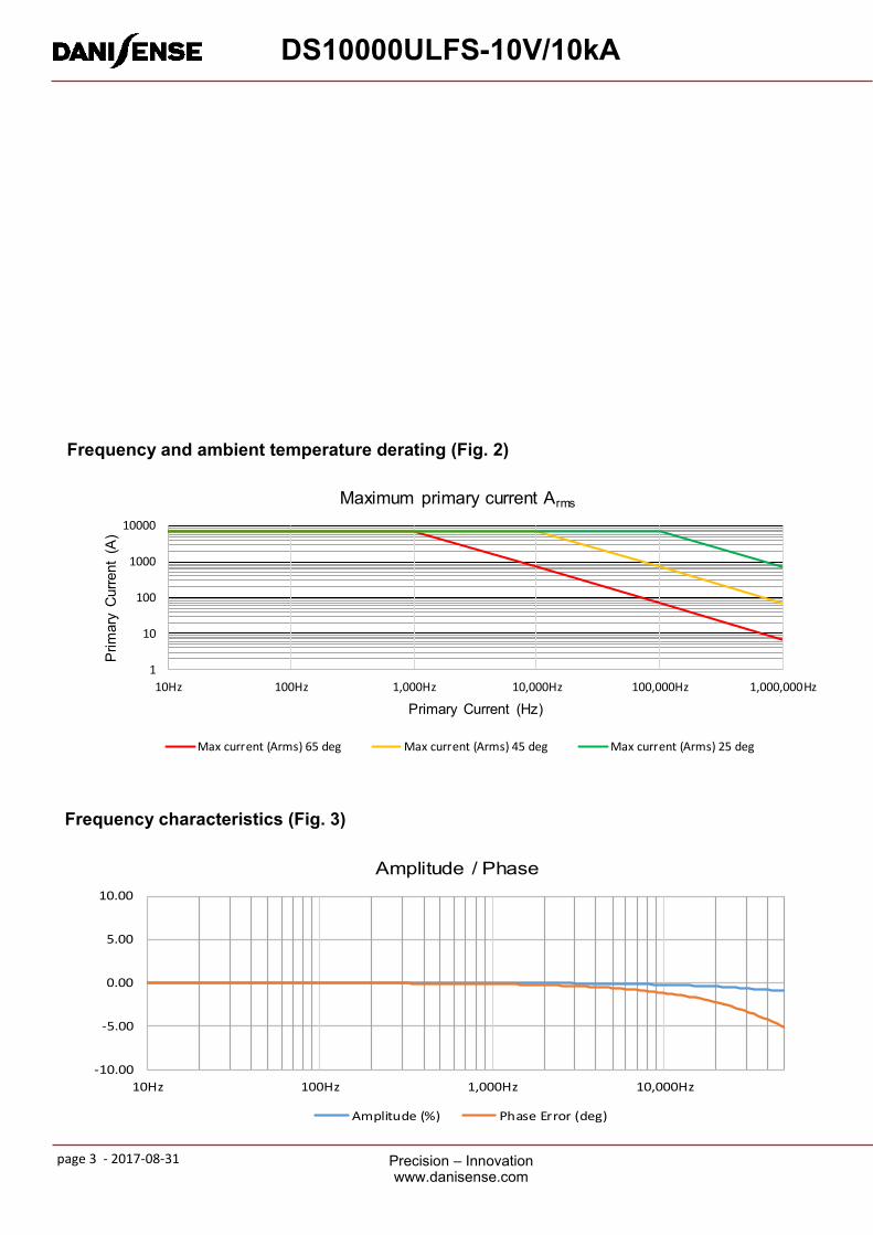
Frequency and ambient temperature derating (Fig. 2)
Frequency characteristics (Fig. 3)
-10.00
-5.00
0.00
5.00
10.00
10Hz 100Hz 1,000Hz 10,000Hz
Amplitude / Phase
Amplitude (%) Phase Error (deg)
1
10
100
1000
10000
10Hz 100Hz 1,000Hz 10,000Hz 100,000Hz 1,000,000Hz
Prim
ary
Curr
ent
(A)
Primary Current (Hz)
Maximum primary current Arms
Max current (Arms) 65 deg Max current (Arms) 45 deg Max current (Arms) 25 deg
page 4 - 2017-08-31 Precision – Innovation www.danisense.com
DS10000ULFS-10V/10kA
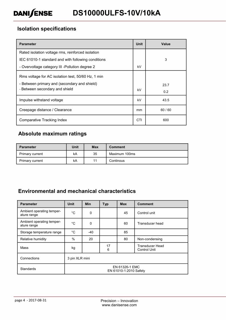
Isolation specifications
Parameter Unit Value
Rated isolation voltage rms, reinforced isolation IEC 61010-1 standard and with following conditions - Overvoltage category III -Pollution degree 2
kV 3
Rms voltage for AC isolation test, 50/60 Hz, 1 min - Between primary and (secondary and shield)
- Between secondary and shield
kV
23.7 0.2
Impulse withstand voltage kV 43.5
Creepage distance / Clearance mm 60 / 60
Comparative Tracking Index CTI 600
Absolute maximum ratings
Parameter Unit Max Comment Primary current kA 35 Maximum 100ms
Primary current kA 11 Continous
Environmental and mechanical characteristics
Parameter Unit Min Typ Max Comment Ambient operating temper-ature range °C 0 45 Control unit
Ambient operating temper-ature range °C 0 60 Transducer head
Storage temperature range °C -40 85
Relative humidity % 20 80 Non-condensing
Mass kg 17 6
Transducer Head Control Unit
Connections 3 pin XLR mini
Standards EN 61326-1 EMC EN 61010-1:2010 Safety
page 5 - 2017-08-31 Precision – Innovation www.danisense.com
DS10000ULFS-10V/10kA
Advanced Sensor Protection Circuits “ASPC” Developed to protect the current transducer from typical fault conditions:
• Unit is un-powered and secondary circuit is open or closed
• Unit is powered and secondary circuit is open or interrupted Both DC and AC primary current up to 100% of nominal value can be applied to the current transducers in the above situations without damage to the electronics. Please notice that the sensor core can be magnetized in all above cases, leading to a small change in output offset
current (less than 10ppm)
Package content • Transducer head
• Electronics box 19” 2U
• AC power cable - Region specific
• 5m cable between transducer head and electronics box (Custom sizes can be delivered at extra charge)
• 2m XLR mini cable to connect the voltage output to 4mm banana plugs (+, - and cable shield)
page 6 - 2017-08-31 Precision – Innovation www.danisense.com
DS10000ULFS-10V/10kA
140mm
DS10000 Transducer Head Dimensions

page 7 - 2017-08-31 Precision – Innovation www.danisense.com
DS10000ULFS-10V/10kA
User Guide
Intended use:
The DS10000ULFS-10V/10kA is intended to measure the current flowing through the aperture of the transducer head. The
measured current is available as a voltage output on the XLR mini connector (2m cable is included with 4mm safety banana
plugs). The voltage output is 10V/10kA.
Instruction for use:
1. Do not apply primary current through the transducerhead before everything is connected and powered.
1. Cable from transducer head to electronics control box must be connected
2. The electronics control box needs to be mains powered. (Universal input)
2. If the electronics control unit is intended for desk use, mount the rubber feet which are part of the package. If the
electronics control unit is intended for Rack mounting, use the screw kit for mounting and do not mount the rubber feet.
3. Connect a precision voltage analyzer to the XLR cable for analysis purposes.
Indications:
When mains is applied a green light diode on the front under the power symbol will light green, indicating the transducer
is working and is tracking the input signal.
Safety Instructions:
DO NOT TRY TO DISASSEMBLE THE UNIT.
Make sure that the unit is properly connected to earth ground.
Do not block the ventilation openings on the side panels.
If the fan does not operate properly contact Danisense for repair.
If the “POWER” green diode is not operating when mains is applied, disconnect power and contact Danisense for further in-
struction.
CE Statement:
This product has been tested and found to comply with the following standards.
Electrical safety: EN 61010-1 2010
Electromagnetic Compatibility: EN 61326-1 2013