
Ultra - Pro Installation & Operations Guide - Zilmet - Pro Installation & Operations Guide....
12
Ultra - Pro Installation & Operations Guide
Transcript of Ultra - Pro Installation & Operations Guide - Zilmet - Pro Installation & Operations Guide....

Ultra - Pro Installation & Operations Guide

Operation Overview
The ULTRA PRO range of Expansion Vessels is specifically designed for Unvented Potable Systems to deal with increased water volume resulting from heat expansion, Solving issues of “water hammer” phenomenon, or reducing number of pump operations or duration of pump run. All vessels of 100 Litres capacity or greater have a second water connection point at the top of the vessel which can be used for a variety of purposes.
Operation overview for Heat Expansion Purposes
The purpose of these vessels is to accommodate the increased liquid volume which occurs during system heating in an Unvented Circuit. A pressurised membrane allows ingress/egress of the liquid during periods of heating / cooling thus providing space for the expanded fluid volume to reside and prevent system pressure increase.
The sensible contraction of system water volume during cooling periods is enabled by means of a compressed air cushion which returns this temporarily expanded volume to the system.
The correct size of vessel must be considered prior to installation and installed by appropriately trained engineers. Careful consideration of pre charge must also be made as this is dependant on the application of the vessel. The larger size range available accommodates the larger systems and is also compatible with chilled water systems.
Operation overview for Water Hammer (Shock) Arrester Purposes
Also known as Hydraulic Shock, water hammer is a specific phenomenon and is not a “Catch all” phrase for noisy pipes. The fitting of an ULTRA PRO vessel will not resolve system noises where the root cause is excessive dynamic pressure, improperly clipped pipework or pipe bore restrictions due to clogged filters, burrs on cut pipe or excessive “bushing down” of distribution pipework.
Water hammer is caused when a water supply outlet is closed very suddenly. This causes a change in the momentum of the water when the system suddenly goes from a lower running pressure to a higher static pressure. This momentum impacts against the now closed outlet resulting in a potentially loud banging noise. This is commonly found in “quarter turn” type tap outlets and washing machines with solenoids controlling flow.
Siting a relatively small ULTRA PRO as close to the source of the noise as possible will cause the vessels diaphragm to flex in response to this momentum change and prevent the audible impact against the terminal fittings. The pre charge should ideally be set to just slightly above the dynamic pressure of the system it is fitted to. This principle also applies to Pressure Reducing Valves, where the momentum of changing water velocities can cause the PRV to be overwhelmed above it’s pre-set value.
Installation & Maintenance Guide
08/2012
Installation Siting
The Expansion Vessel may be fitted to a very wide range of systems, different sources of heat are applied to Unvented Hot Water Systems, and as long as the temperature and pressure is controlled within normal limits, the ULTRA-PRO will be compatible in it’s application.
Installations where the heat source is augmented by Solid Fuel, Solar Thermal or other heat sources with potentially uncontrolled input temperatures are not compatible with these vessels and an alternative model and installation method should be specified.
The physical siting and commissioning of the vessel should always be in accordance with the instructions relating to any associated equipment as each application may have a number of acceptable siting options or locations.
Our requirements are simply that the vessel be installed in a way that allows future access, and ideally be in the coolest available part of the system to assist with longevity of the membrane. At no time can a vertical vessel be mounted horizontally, or be mounted to a wall or framework suspended by it’s legs.
Installation & Maintenance Guide
08/2012
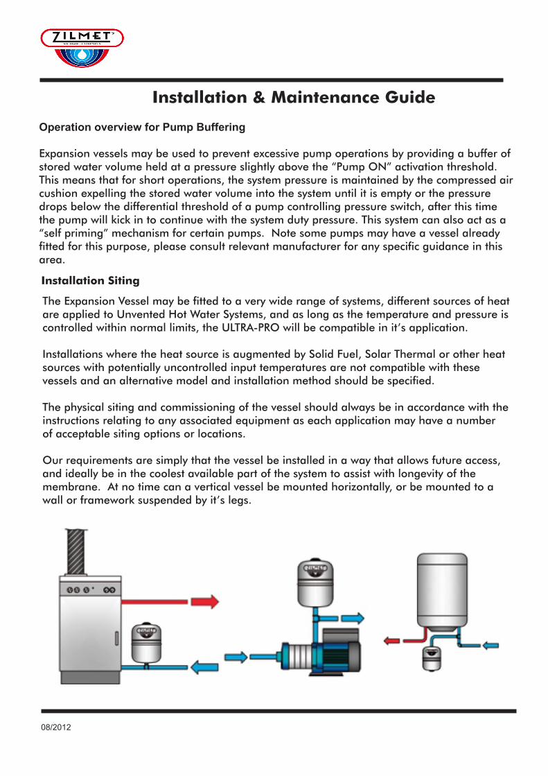
Operation overview for Pump Buffering
Expansion vessels may be used to prevent excessive pump operations by providing a buffer of stored water volume held at a pressure slightly above the “Pump ON” activation threshold. This means that for short operations, the system pressure is maintained by the compressed air cushion expelling the stored water volume into the system until it is empty or the pressure drops below the differential threshold of a pump controlling pressure switch, after this time the pump will kick in to continue with the system duty pressure. This system can also act as a “self priming” mechanism for certain pumps. Note some pumps may have a vessel already fitted for this purpose, please consult relevant manufacturer for any specific guidance in this area.
Installation & Maintenance Guide
08/2012
The UK Water Supply Industry Recommendations for Pressure testing state:-
“When testing rigid pipe systems all the outlets in the installation should be sealed and all float operated valves should be capped off or isolated. The water pressure should then be increased, by pumping, until the internal water pressure at the lowest point of the installation is 50% above the normal operating pressure. This pressure should be maintained for one hour without further pumping”.
Where the expansion vessel is concerned, there may be times when this testing procedure will take the system pressure to something in excess of the maximum working pressure. At times like this there is the potential to burst the membrane. This is due to the tremendous strain that the membrane is subjected to in these conditions, which is caused ultimately by a greatly increased “acceptance factor”.
The acceptance factor in this case is essentially the percentage of the overall vessel volume which is filled.
In order to successfully pressure test the system without endangering the membrane, it is necessary to increase the pre charge of the vessel temporarily to a magnitude that prevents the acceptance factor exceeding 40% while the maximum working pressure is exceeded.
The method of calculating the increased pre charge required is:-
Where,
P = Initial charge pressure (Absolute) - This should equal the value of the static system i
pressure minus 0.2 Bar.
P = Maximum operating pressure (Absolute) of the Safety Relief Valve, taking into account f
any differences in height between the vessel and the safety relief valve.
(P /P ) x 100 = acceptance factori f
If acceptance factor exceeds 40% then increase P until this is not so. i
P = final value of pre charge required before system pressure test.i
For example if the normal operating pressure of a system is 9 Bar, then the expected test pressure for the system is 13.5 Bar.
Because this exceeds the maximum working pressure, the pre charge should be temporarily increased to something like 5.4 Bar or more if possible. In this way, the integrity of the vessel is still tested properly without undue risk to the membrane.
SizingThe appropriate sizing of an expansion vessel must be undertaken by qualified or appropriately trained engineers. Due to the variable nature of pump control systems we regrettably can provide no further specific examples or guidance for pump applications other than heat expansion.
08/2012
Installation & Maintenance Guide
The vessel requires inspection at least once a year (or as and when a drop in performance is noted from the system). The vessel must be visibly inspected for pinholes in the metal body of the vessel and the air pressure must be checked against the required pre-charge. Some pressure loss is to be expected and should be rectified to within a reasonable accuracy but a significant drop in air pressure may signify that the vessel membrane is nearing the end of it’s life span and may require replacement. Some provision should be made within a wider piece of equipment for access and inspection. Full instructions regarding membrane replacement are available separately.
The air pressure may only be inspected when the vessel is either detached completely from the system or when the system itself is de-pressurised to atmospheric pressure.
Over time, the flanges of a vessel with an interchangeable vessel will be exposed to repeated strain, eventually this may give rise to leaks from the flanged connections. These flanges are replaceable and are available in both Stainless and Galvanised Steel.
Maintenance
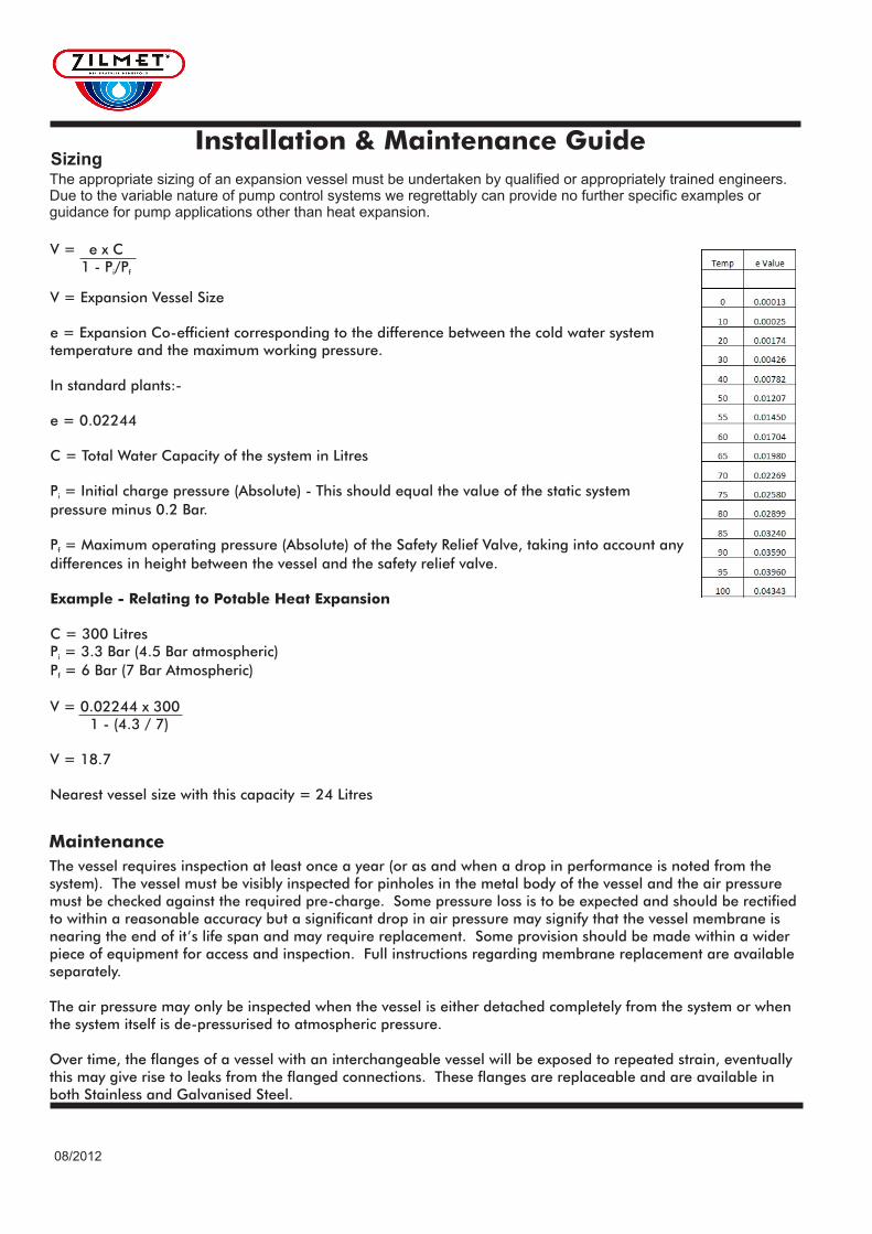
V = e x C 1 - P/Pi f
V = Expansion Vessel Size
e = Expansion Co-efficient corresponding to the difference between the cold water system temperature and the maximum working pressure.
In standard plants:-
e = 0.02244
C = Total Water Capacity of the system in Litres
P = Initial charge pressure (Absolute) - This should equal the value of the static system i
pressure minus 0.2 Bar.
P = Maximum operating pressure (Absolute) of the Safety Relief Valve, taking into account any f
differences in height between the vessel and the safety relief valve.
Example - Relating to Potable Heat Expansion
C = 300 LitresP = 3.3 Bar (4.5 Bar atmospheric)i
P = 6 Bar (7 Bar Atmospheric)f
V = 0.02244 x 300 1 - (4.3 / 7)
V = 18.7
Nearest vessel size with this capacity = 24 Litres

08/2012
MaterialsShell: Carbon SteelConnection: Galvanised / Stainless SteelMembrane: Butyl / EPDM
oMax Operating Temperature: 70 CColour: Blue / Red
Code Capacity Diameter Height Length Pmax Pre charge Connection
(Litres) (mm) (mm) (mm) (Bar) (Bar) (BSP)
1100002406 24 Horizontal 270 290 485 15 1.5 1" G
1100002418 24 Vertical 270 485 - 10 1.5 1" G
1100005007 50 Horizontal 380 410 560 10 1.5 1" G
1100005006 50 Vertical 380 770 180 10 1.5 1" G
1100006007 60 Horizontal 380 410 640 10 1.5 1" G
1100006006 60 Vertical 380 860 170 10 1.5 1" G
1100008005 80 Horizontal 380 860 170 10 1.5 1" G
1100008005 80 Vertical 270 349 730 10 1.5 1" G
1100010007 100 Litre Horizontal 450 270 153 10 1.5 1" G
1100010006 100 Litre Vertical 450 910 153 10 1.5 1" G
1100020007 200 Litre Horizontal 550 580 985 10 1.5 1 1/2" G
1100020006 200 Litre Vertical 550 1235 210 10 1.5 1 1/2" G
1100030007 300 Litre Horizontal 630 660 1140 10 1.5 11/2" G
1100030006 300 Litre Vertical 630 1365 188 10 1.5 1 1/2" G
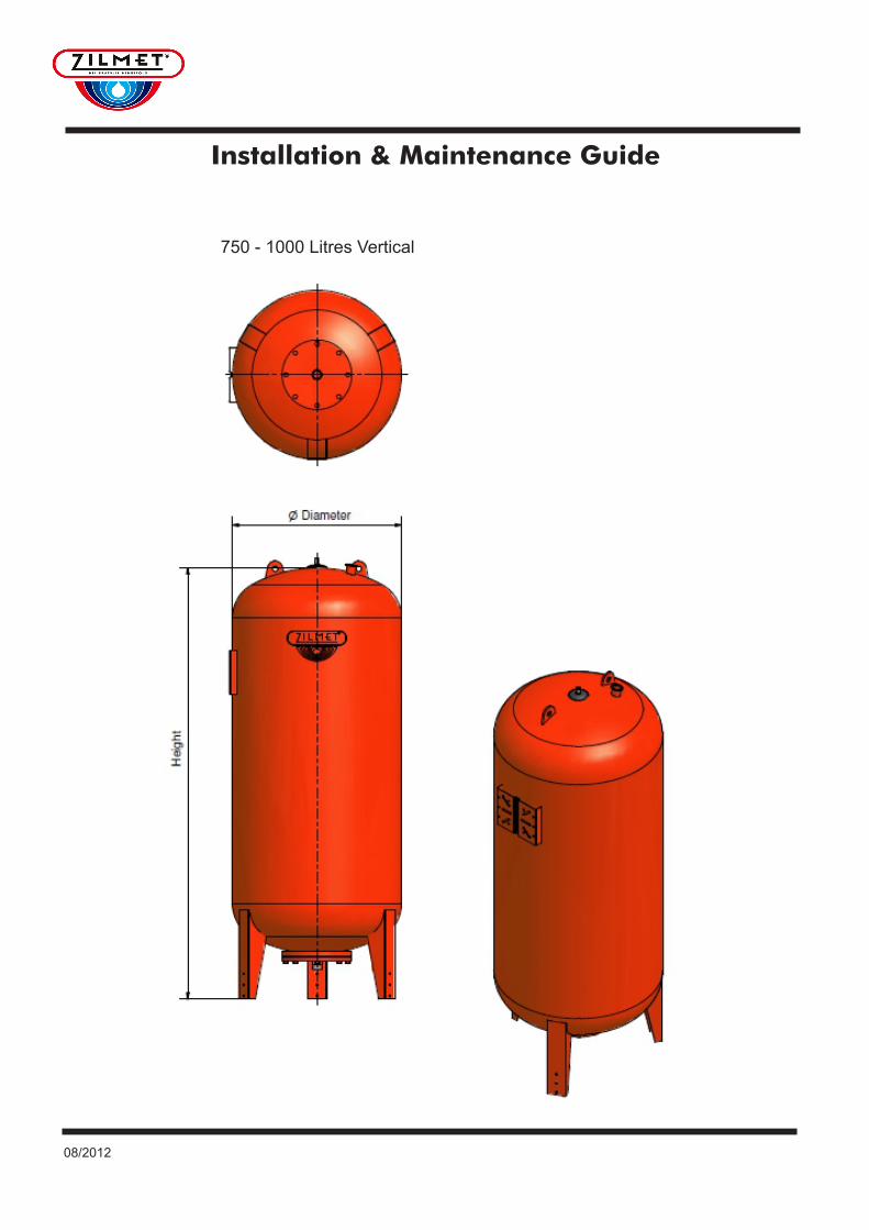
1100050006 500 Litre Vertical 750 750 1560 10 1.5 1 1/2" G
1100075057 750 Litre Vertical 750 750 2075 10 1.5 1 1/2" G
1100100056 1000 Litre Vertical 850 2100 120 10 1.5 1 1/2" G
1100150002 1500 Litre Vertical 960 2420 220 10 4 2" G Fem
1100200001 2000 Litre Vertical 1100 2555 290 10 4 2" G Fem
1100300000 3000 Litre Vertical 1200 2800 220 10 4 2 ½" G Fem

08/2012
MaterialsShell: Carbon SteelConnection: Galvanised / Stainless SteelMembrane: Butyl / EPDM
oMax Operating Temperature: 70 CColour: Blue / Red
Code Capacity Diameter Height Length Pmax Pre charge Connection
(Litres) (mm) (mm) (mm) (Bar) (Bar) (BSP)
1100002423 24 Vertical 270 485 - 16 2 1" G
1100002435 24 Horizontal 270 290 485 16 2 1" G
1100010055 100 Vertical 450 910 - 16 2 1" G
1100020052 200 Vertical 550 1235 - 16 2 1 1/2" G
1100030048 300 Vertical 630 1365 - 16 2 1 1/2" G
1100050050 500 Vertical 380 860 - 16 2 1 1/2" G
1100075060 750 Vertical 380 860 - 16 2 1 1/2" G
1100100060 1000 Vertical 850 2100 - 16 2 1 1/2" G
24 Litre Horizontal
08/2012
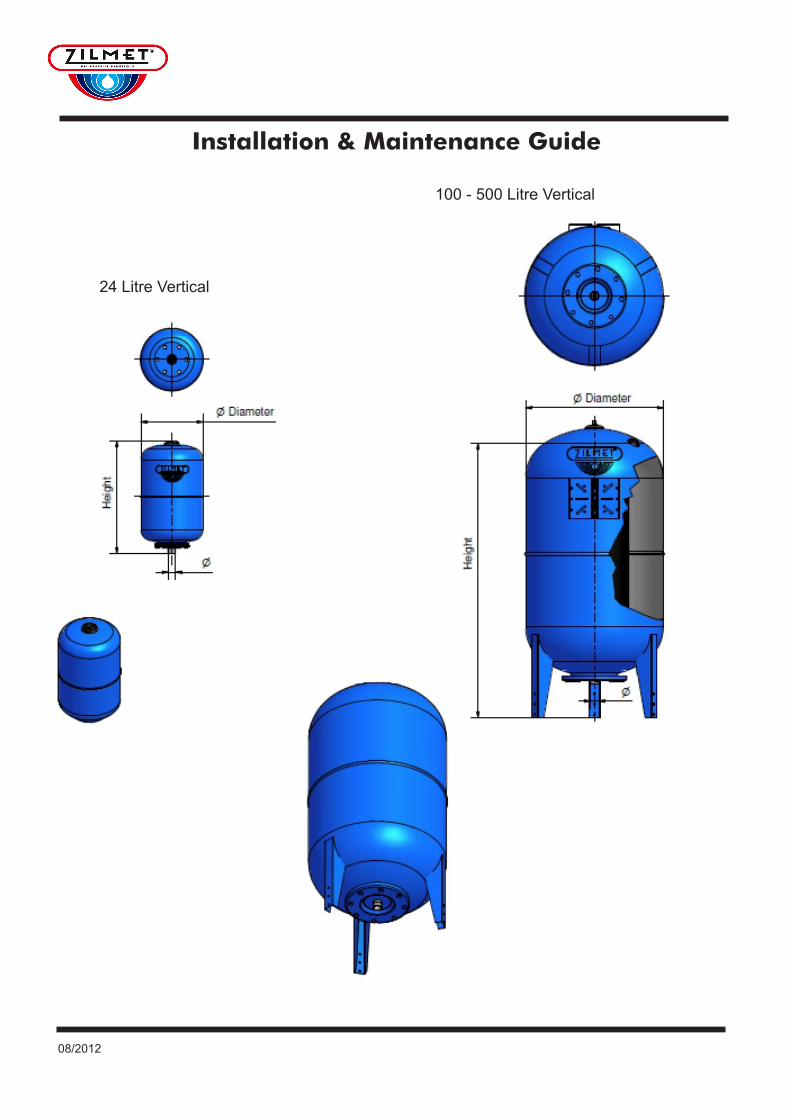
24 Litre Vertical
100 - 500 Litre Vertical
08/2012
750 - 1000 Litres Vertical

08/2012

Notes
08/2012
Zilmet UK Ltd. Airfield Industrial Estate, Hixon,Staffordshire, ST180PF
t: 01889272185, F: 01889272191web: www.zilmet.co.uk, E Mail: [email protected]
E & OE