UIVERSITI TEKIKAL MALAYSIA...
24
UIVERSITI TEKIKAL MALAYSIA MELAKA DESIG, AALYSIS AD DEVELOP KR-150 GO-KART This report submitted in accordance with requirement of the Universiti Teknikal Malaysia Melaka (UTeM) for the Bachelor Degree of Manufacturing Engineering (Manufacturing Design) with Honours. by JAMIESHAH BI JAMIL FACULTY OF MANUFACTURING ENGINEERING
Transcript of UIVERSITI TEKIKAL MALAYSIA...

U�IVERSITI TEK�IKAL MALAYSIA MELAKA
DESIG�, A�ALYSIS A�D DEVELOP KR-150 GO-KART
This report submitted in accordance with requirement of the Universiti Teknikal
Malaysia Melaka (UTeM) for the Bachelor Degree of Manufacturing Engineering
(Manufacturing Design) with Honours.
by
JAMIESHAH BI� JAMIL
FACULTY OF MANUFACTURING ENGINEERING


i
ABSTRACT
The existing design of go-cart is not suitable for road driving. This is because of the
height measurement of existing go-cart where it is lower than the daily vehicle while
the lack of suspension system in existing go-cart’s design will cause the use of
existing go-cart on the road is not relevant and has many problems in terms of safety
factors. After doing some studies on the measurement and the design of go-cart, the
new innovation design is produce which is called GK-150. GK-150 is the suitable
design to drive on the road or on the racing circuit. GK-150 is operational with the
suspension system and 150cc engine. The height measurement of the go-cart is also
capable passing bumpers and can be used as a racing vehicle or daily use.
ii
ABSTRAK
Rekabentuk go-kart yang sedia ada adalah tidak sesuai untuk di pandu di jalan raya.
Ini kerana ukuran ketinggian bagi Go-kart sedia ada adalah lebih rendah daripada
kenderaan seharian manakala ketiadaan sistem perendam di dalam rekabantuk go-
kart sedia ada menyebabkan penggunaan go-kart di atas jalan raya adalah tidak
relevan serta mempunyai banyak masalah dari segi faktor keselamatan. Setelah
membuat kajian ke atas ukuran dan rekabentuk go-kart yang sedia ada, lahirlah
rekabentuk inovasi yang dinamakan GK-150. GK-150 adalah rekaan yang sesuai
dipandu di jalanraya mahupun di atas litar perlumbaan. GK-150 dilengkapi dengan
sistem perendam dan enjin berkuasa 150cc. Ukuran ketinggiannya juga
berkeupayaan melepasi bonggol serta boleh dijadikan alat perlumbaan atau
kenderaan kegunaan harian.

iii
DEDICATIO�
“Special dedicated to my parents, Mr. Jamil Bin Hj. Ngajis and Mrs. Hjh. Mazlina Binti
Hj Yusop and family for their understanding and support to finish this thesis. Special
thanks to my supervisor, Mr.Ir.Sivarau A/L Subramonian for his encouragements,
advices, and motivational supports for me to finish this thesis. Thanks a lot to my
colleagues for giving supports and their keenness helping me during my thesis.
“May Allah be with us”

TABLE OF COTET
CHAPTER 1 ITRODUCTIO
1.0 Introduction 1
1.1 Background of Project 1
1.2 History of Go-kart 2
1.3 Problem Statement 5
1.4 Objective of the Project 5
1.5 Scope of Project 6
1.6 Summary 6
1.7 Outline of Thesis 6
CHAPTER 2 LITERATURE REVIEW
2.0 Introduction 7
2.1 Basic go kart chassis theory 7
2.1.1 Chassis Design 8
2.1.2 Body and frame Construction 8
2.1.3 Unit body construction 9
2.1.4 Space frame construction 9
2.1.5 Platform 10
2.1.6 Go-kart frame 10
2.1.7 Chassis material 11
2.2 Evaluating Go kart Chassis 12
2.3 Kart Scaling & Weight Distribution 12
2.4 The effect of chassis flexibility in the go kart chassis 15
2.5 Frame Construction 16
2.5.1 Side bite 16
2.5.2 Torsion bars 17
2.6 Steering System 17
2.6.1 Steering Geometry 17
2.7 Brakes System 22
2.8 COSMOSWorks 24

2.9 Summary 25
CHAPTER 3 METHODOLOGY
3.0 Introduction 26
3.1 Initial Data Collection Go-Kart 27
3.1.1 Secondary Sources 27
3.1.2 Primary Sources 27
3.2 Development Design 28
3.2.1 Conceptual Design of Go-Kart 28
3.3 Preliminary Design Sketch 28
3.4 Concept Selection for System Application. 32
3.5 Detail Design 45
3.6 Materials Conformation 49
3.6.1 Design Analysis of Go-Kart Frame 49
3.7 Development of Go-kart 50
3.8 Testing 51
3.9 Improvement 52
3.10 Summary 52
CHAPTER 4 RESULT AD DISCUSSIOS
4.1 Introduction 53
4.2 Static Analysis 53
4.2.1 COSMOSXpress Analysis 56
4.2.2 Case Study 58
4.2.2.1 Go-kart Design 58
4.2.3 Procedure Using COSMOSXpress 58
4.2.4 Static Analysis Result 66
4.2.4.1 Chassis Go-kart Analysis 66
4.2.4.1 Back Chassis Go-kart Analysis 76
4.2.4.3 Front Arm Analysis 79

CHAPTER 5 COCLUSIO AD RECOMMEDATIO
5.0 Introduction 82
5.1 Conclusion 82
5.2 Recommendation 83
REFERECES

LIST OF FIGURES
1.1 Don Boberick driving the “Drone” 3
1.2 This is the old Drone testing on the new "Azusa" track in early 3
1959
1.3 Go Kart Manufacturing Company’s class "B" drivers 4
1.4 The Karter magazines February edition 4
2.1 Body and Frame construction 8
2.2 Unit Body Construction 9
2.3 Space frame construction 10
2.4 Go Kart Frame or Chassis 11
2.5 Input calculation 13
2.6 VCG calculation 14
2.7 Weight Distribution 14
2.8 Chassis wizard 15
2.9 Lifted rear tyre 16
2.10 Ackerman Steering 18
2.11 King pin inclination 19
2.12 Castor Angle 20
2.13 Camber Angle 21
2.14 Toe-in 21
2.15 Friction Brakes 23
2.16 Component of Hydraulic Brake System 23
2.17 Finite element method in COSMOSworks 25
3.1 Project Flow chart 26
3.2 Sketch 1 29
3.3 Sketch 2 30
3.4 Sketch 3 31

3.5 Datum design 35
3.6 Steering system (rack and pinion) 40
3.7 Steering system 41
3.8 Chassis 42
3.9 Disc Brake 43
3.10 Exploded view of disc brake 44
3.11 Motorcycle Suspension 44
3.13 Technical Drawing of GK-150 Front Frame 45
3.14 Technical Drawing of GK-150 Back Frame 46
3.15 Technical Drawing of GK-150 Front Arm 47
3.16 Technical Drawing of GK-150 Steering Arm 48
3.17 Plain carbon steel 49
3.18 Structural analysis 50
4.1 Analyzing go-kart chassis using COSMOSXpress 55
4.2 The flow of Static analysis using COSMOSXpress analysis 57
4.3 Create material properties 59
4.4 Resistant displacement 62
4.5 Load displacement 63
4.6 Force value 64
4.7 Result of safety factor 65
4.8 Failure result on stress distribution 65
4.9 Go-Kart chassis design 1 66
4.10 Go-kart chassis design 2 66
4.11 Go-Kart chassis design 3 67
4.12 Graph result for chassis design 1 68
4.13 Stress distribution result on chassis design 1 69
4.14 Graph result for chassis design 2 71
4.15 Stress distribution result on chassis design 2 72
4.16 Graph result for chassis design 73
4.17 Stress distribution result on chassis design 3 74
4.18 Graph factor of safety for 3 selected chassis design 75
4.19 Graph result of safety factor for back chassis 78
4.20 Stress Distribution result of back chassis 78
4.21 Graph factor of safety result for front arm design 80
4.22 Stress Distribution result for front arm 81

LIST OF TABLES
3.1 Pugh’s concept selection method 33
3.2 Steering system concept selection 36
3.3 Chassis concept selection 37
3.4 Brakes Disc System concept selection 38
3.5 Suspension system concept selection 39
4.1 Material in Solidworks Software 60
4.2 Plain Carbon Steel physical properties 61
4.3` Data static analysis for chassis design 1 67
4.4 Data static analysis for chassis design 2 69
4.5 Data static analysis for chassis design 3 72
4.6 Factor of safety for chassis design 76
4.7 Data static analysis for back chassis design 77
4.8 Data static analysis for front arm 79

1
CHAPTER 1
I�TRODUCTIO�
1.0 Introduction
Go-kart or karting was born from United States in 1950s, where the engine mainly
from discarded lawn engine. Go-kart is a driving and racing miniature, skeleton
frame, and rear engine automobiles called karts (DiNozzi, 1999). Go-kart is a non
popular sport previously, but today it has become one of the most popular sports by
multiple group of age. Now days, racing go-karts are considered as one of the most
economic activity where a large number of people can participate.
1.1 Background
In the new millennium, we regularly heart about motorsport racing such as formula
one, NASCAR, rally art and many more, which are used popular in the western
countries but nowadays it has been wide separate in the developing countries. Those
motorsports activity is mainly popular for the rich people because of restrict by the
regulations and further more high cost. In contrast, go-kart motorsport gives chances
to low income people to get involved in legal racing with less restricted by regulation
and low budget needed. Seven times formula one World champion, Michael
Schumacher started his involvement in motorsports with karting. He joined go-kart
motor sports at his hometown, Germany and won his first go-kart championship at
the age 19 years old (McAuley. J, 2008). All go-karts look alike, but the fact is that
go-karts have its own classes such as sprint kart, road racing kart, indoor karting and
speedway karting. In addition, with small engine and skeleton frame go-karts speed
can speed up to 100 miles per hours with a weight up to 210 pounds.

2
The development in karting has expanded rapidly together with advanced
technology. As this motorsport become popular among citizens, those go-karts
manufactures started to do more research and development to improve the go-kart in
terms of the chassis design, speed, braking system and transmission system. Today’s,
go-kart frames are made from lighter iron, chromoly and others which is more
durable and it can absorb more vibration even if it has no suspension. Designers,
engineers and others have involved directly towards new achievement in improving
all aspects in the go-kart. The usage of advanced technology in manufacturing is
widely utilized to invent a better go-kart.
1.2 History of Go-kart
In 1958, go-kart was already a popular racing motor sports especially among locals
around USA. The history took placed at Rose Bowl in Pasadena, California. One of
the significant names of this sport was Don Boberick. He started his participation in
karting when he was still working at Art angels. Art Angels, Duff Livingstone and
plenty of individuals was the participant of motor racing type of events at rose bowl
parking lot (DiNozz, 1999). Roy Desbrow had constructed a kart named the “Drone”
and he was also a business partner of Duffy Livingstone. The kart was powered by
250cc engine originally used in a U.S Army radio controlled drone air plane
(DiNozzi, 1999). Don Boberick was the driver to the kart at the rose bowl kart
competition. At the same time Don was also contacted by Jim Rathman to drive the
latest kart design at GKCA (Go-kart Club of America) Nationals called FIRST
Rathman Xterminator prototype kart in 1959 (Figure 1.1).

3
Figure 1.1: Don Boberick driving the “Drone” (www.vintagekarts.com,
1999)
In 1959, the world of go-kart revaluated to be more organized event as Don
Boberick, Duffy Livingstone, Marvin Patchen the advertising manager of Peterson
Publishing Cooperation and few members agreed to form an organized pattern called
Go-kart Club of America (GKCA) to manage and organized motor racing at an
inexpensive level (DiNozzi, 1999). The role of this organization was to prepare the
technical regulation that could comprise the competition. Dick Van der Veer was the
first president of the GKCA. Duffy Livingstone and partners, Res Desbrow and Bill
Rowles built a new go-kart Mfg.Facalitiy in Azusa, California in 1959 (Figure 1.2)
(DiNozzi. B, 1999).
Figure 1.2: This is the old Drone testing on the new "Azusa" track in early
1959 (www.vintagekarts.com, 1999)

4
In 1960, in California they had their own racing team such as Go-kart Manufacturing
and Bug who already had their own facilities like bus transports. During that time,
there was Championship held at Rockford, IL, for the North American Kart
Association (NAKA) National Championships in California.
Figure 1.3: Go-kart Manufacturing Company’s class "B" drivers
(www.vintagekarts.com, 1999)
In 1961, GKCA published kart magazines named “The Karter” issued on the
February 1961. Then GKCA became International Kart Federation (IKF) initiated by
GKCA president 1961 for the reason of it was important to divide the kart club and
the manufacturer (DiNozzi, B, 1999).
Figure 1.4: The Karter magazines February edition
(www.vintagekarts.com, 1999)

5
1.3 Problem Statement
Most of the manufacturer of go-kart used to design for go-kart circuit only but not for
the normal road in Faculty of Manufacturing Engineering (FKP) or even the world.
At the moment the engine for go-kart has a very low central fugal gravity force in
order to stabilize the go-kart but it can not used for normal road, which is used to be
rough in some part of the road. This is the main problem for current go-kart chassis
design available in the market.
Based on this problem, this research would like to modify or improved the current
go-kart chassis for more comfortable design which is suitable not only for go-kart
circuit but also for normal road. This research project will redesign the go-kart
chassis to suit the go-kart circuit as well as for normal road. In order to it more
feasible, the new design go-kart chassis will used KR-150 go-kart engine so that the
horse power for this engine is manage to carry total weight of the go-kart including
driver.
1.4 Objective of the Project
The general objectives of the project is the modify or redesign the go-kart chassis for
better performance in the go-kart circuit and normal roads. The specific objectives
are as follow:
(a) To construct the optimum design of go-kart for better performance.
(b) To assemble the KR-150 engine in the new go-kart chassis which has
been develop.
(c) To test dynamically for its performance and suitability of campus use.
The new developed of go-kart should be more versatile and suitable to used the
UTeM campus in the near future.
6
1.5 Scope of Project
The scopes of the project are as follow:
• To suite the KR-150 engine into develop chassis.
• To mount disc break application.
• To apply the simple design of steering system to suite into GK-150
project.
• To apply the suitable suspension system into GK-150 project
1.6 Summary
As a summary, this chapter listed the objectives, significant and scopes of the project
and problem statements. The objectives of this project will ensure that this project
has a target to be achieved. From the chapter, it allows the author to be known what
needs to be done in completing the project such as the project requirements and the
product of the project.
1.7 Outline of Thesis
The objectives, significant and scope of the project are explained including the
problem statements. The main important thing is the objectives of this project.
Significance of project is more about what this project is done for. Then, the scope of
the project tells about what are the project requirements and the product of the
project. The methods and the procedures that involve in this project are discussed
more in the project methodology.
7
CHAPTER 2
LITERATURE REVIEW
2.0 Introduction
This chapter focuses on all features of go-kart parts which is to modify go-kart
design with different types of material used. In addition, this chapter also
emphasizes on information needed crucially to encounter the problem to the existing
go-kart. This chapter also discusses the definition of all go-kart features, basic go-
kart theory on every part or system, effect of chassis flexibility and COSMOSworks
express using Solidworks.
2.1 Basic go-kart chassis theory
According to Martin, (2000), it is the responsibility of the karter to determine his
own requirement and to obey the rules stated by the organization. This is true
because the option of setting up the go-kart such as which type of chassis preferable
depends to the convenience of the karter. The combination of knowledge and
experienced would the best requirement to set up a good chassis. The understanding
of basic chassis setup would assist the rookie on setting up the chassis but
experienced will lead to improvement and development in tuning up the chassis.
Furthermore, the fundamental of go-kart needed crucially as a main reference for the
author to design new chassis.
8
2.1.1 Chassis Design
Chassis is a frame on which the body of an automobile or air plane is mounted
(Licker, 2003). Typically, chassis designs have three basic designs. There are frame,
unit body and space frame construction. According to Capitani (2007) go-kart is the
simplest form of motorsport run with small cars with essential shape. The essential
shape refers to the tubular form of the frame. The author agreed with Capitani view,
because based on the author study most go-karts are made from hollow steel tubing.
Referring to the existing go-kart, the chassis was too stiff. Therefore, to solve this
problem, the author has designed a new chassis with longer rails to increase the
flexibility and improve the go-kart handling.
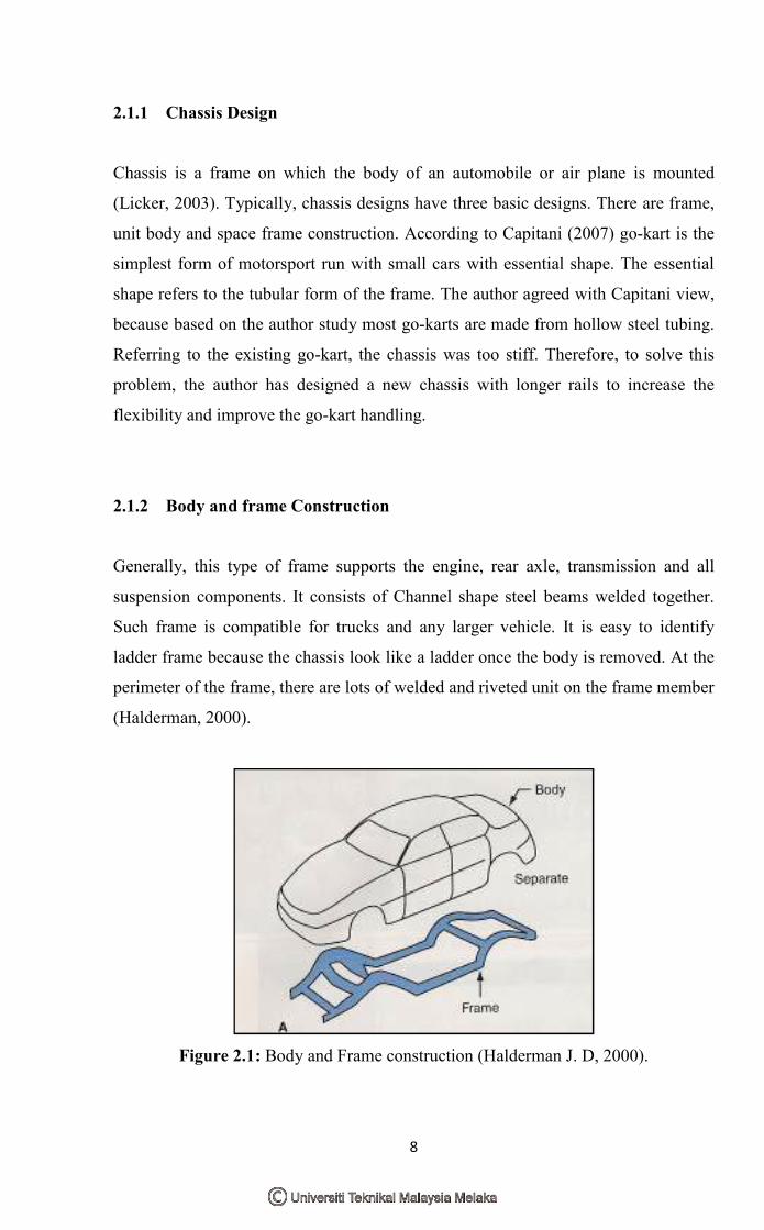
2.1.2 Body and frame Construction
Generally, this type of frame supports the engine, rear axle, transmission and all
suspension components. It consists of Channel shape steel beams welded together.
Such frame is compatible for trucks and any larger vehicle. It is easy to identify
ladder frame because the chassis look like a ladder once the body is removed. At the
perimeter of the frame, there are lots of welded and riveted unit on the frame member
(Halderman, 2000).
Figure 2.1: Body and Frame construction (Halderman J. D, 2000).

9
2.1.3 Unit body construction
Unit body construction can be defined as a combination of body and the structure of
the frame. The body itself consists of stamped panels welded together and functions
to support the engine drive line components, suspension and steering components.
The shape of the body influences the strength of the chassis. As a study proposed,
this type of chassis consists of 10.000 parts to make it as a complete product
(Halderman, 2000). Figure 2.2 shows the example of unit body construction and an
example of this construction is shows in figure 2.3.
Figure 2.2: Unit Body Construction (Halderman J. D, 2000).
2.1.4 Space frame construction
This type of frame consists of formed sheet metal used to construct a frame work for
the entire vehicle. Such vehicle is drivable with-out the body because the frame
works are all covered with plastics or steel panels (Halderman J. D, 2000).

10
Figure 2.3: Space frame construction (Halderman J. D, 2000)
2.1.5 Platform
Standard platform of a vehicle is referred to its basic size and shape allowing
different vehicle manufactures to insert the same drive train, suspension and steering
components. A platform consists of all major sheet metal components that form the
load bearing structure for a vehicle, including the front suspension and engine
supporting section. A track and wheelbase of the vehicle are the other components of
a platform that affect the handling and ride of a vehicle (Halderman, 2000).
2.1.6 Go-kart frame
A go-kart has a frame provided with longitudinal frame rails, a rear cross member
extended across the rear ends of the longitudinal rails and resiliently connected
thereto, and suspension arms positioned to the sides (Capitani, 2007). The tubular
iron used as the foundation of the chassis itself functioned as a suspension and has
relatively high degree of flexibility. At the back itself, located the engine mounting
on the suspension arm which hold a variety weight of engines. Since the frame show
in figure 2.4 is quite flexible, the wheels of the kart tend to remain in contact with the
ground even where the track has wide surface irregularities. Also, the longitudinal
rails bow upwardly over the rear axle with sufficient clearance to permit axle